


FP2000
Analogue addressable Fire Panel
Reference Guide
LKFP2503
Revision 5 : September 1999
Downloaded from: http://www.guardianalarms.net


Copyright
© Aritech 1998. All rights reserved. No part of this publication may be reproduced, transmitted, stored in a retrieval system, or
transmitted in any form, or by any means – electronic, photocopying, recording, or otherwise – without the prior written permission of
Aritech.

Reference Guide 3

CONTENTS
Description ................................................................................................................................................................................7
Special features .......................................................................................................................................................................7
User friendliness ......................................................................................................................................................................7
Powerful maintenance features .........................................................................................................................................8
Networking ................................................................................................................................................................................8
General features......................................................................................................................................................................8
Standard I/O facilities ............................................................................................................................................................9
Mechanical data ......................................................................................................................................................................9
Led indications and controls.............................................................................................................................................. 11
General indicators................................................................................................................................................................. 11
Controls ....................................................................................................................................................................................13
Sounders.................................................................................................................................................................................. 13
Fire brigade ............................................................................................................................................................................. 14
Other..........................................................................................................................................................................................15
Zone indicators ...................................................................................................................................................................... 15
LCD and Keypad ...................................................................................................................................................................16
Alarm line................................................................................................................................................................................. 17
Valid entries line....................................................................................................................................................................18
Status line................................................................................................................................................................................19
System status menu............................................................................................................................................................ 19
Access to main menu..........................................................................................................................................................20
Main menu .................................................................................................................................................................. 21
System menu............................................................................................................................................................. 23
Configuration menu ................................................................................................................................................. 24
Hardware configuration 1 ...................................................................................................................................... 25
Hardware configuration 2 ...................................................................................................................................... 27
Board information.....................................................................................................................................................28
Memory allocation 1 ................................................................................................................................................29
Memory allocation 2 ................................................................................................................................................30
Panel ID ....................................................................................................................................................................... 31
Communication menu............................................................................................................................................. 33
Port setup ....................................................................................................................................................................34
Network menu ........................................................................................................................................................... 37
Panels ..........................................................................................................................................................................38
Local repeaters ......................................................................................................................................................... 39
Global repeaters ....................................................................................................................................................... 40
Modem menu............................................................................................................................................................. 41
Modem alarm report 1 ............................................................................................................................................ 42
Modem alarm report 2 ............................................................................................................................................ 43
Modem maintenance.............................................................................................................................................. 44
Modem setup 1 ......................................................................................................................................................... 45
Modem setup 2 ......................................................................................................................................................... 46
Modem setup 3 ......................................................................................................................................................... 47
CL devices .................................................................................................................................................................. 48
Access menu............................................................................................................................................................. 49
Access codes............................................................................................................................................................. 50
Field access...............................................................................................................................................................51
Clear site data 1 ........................................................................................................................................................52
Clear site data 2 ........................................................................................................................................................ 54
Set default................................................................................................................................................................... 55
Set times menu......................................................................................................................................................... 58
Set date and time.....................................................................................................................................................59
Output delays ............................................................................................................................................................. 60
Fire brigade delay off times .................................................................................................................................. 61
Sounder delay off times ......................................................................................................................................... 62
Zone off times ............................................................................................................................................................ 63
Zone on times ............................................................................................................................................................ 64
Day mode times ........................................................................................................................................................ 65

Night mode times .....................................................................................................................................................66
Restart menu............................................................................................................................................................. 67
Device menu.............................................................................................................................................................. 68
General setup and view (all types).....................................................................................................................69
Smoke and Heat detec tors...................................................................................................................................73
Manual Call Point.....................................................................................................................................................75
Sounder ....................................................................................................................................................................... 77
Indicating circuit controller.....................................................................................................................................79
Monitor units...............................................................................................................................................................80
Input/output units...................................................................................................................................................... 82
Gas unit I/O (GCU 1).............................................................................................................................................. 84
Zone menu.................................................................................................................................................................. 86
Area menu .................................................................................................................................................................. 89
Zone graphics ............................................................................................................................................................ 91
Zone graphic screen ...............................................................................................................................................92
Graphic device statistics........................................................................................................................................ 93
Device graphics ........................................................................................................................................................ 94
Device graphic screen ............................................................................................................................................ 96
Graphic device setup.............................................................................................................................................. 97
Input/output............................................................................................................................................................................. 98
Common facilities – all input types .....................................................................................................................99
Input definition – type General .......................................................................................................................... 102
Input definition – type Zone ............................................................................................................................... 104
Input definition – type Area................................................................................................................................ 105
Input definition – type Adjacent Area..............................................................................................................106
Input definition – type Internal........................................................................................................................... 107
Input definition – type Time................................................................................................................................108
Input definition – typ e Device Input................................................................................................................. 110
Input definition – type Device............................................................................................................................ 111
Input definition – type Network .........................................................................................................................112
Input definition – type Action............................................................................................................................. 113
Input definition – type Current Loop Device.................................................................................................114
Common facilities – all output types ............................................................................................................... 115
Output definition – type General ......................................................................................................................118
Output definition – type Zone ............................................................................................................................ 119
Output definition – type Area.............................................................................................................................120
Output definition – type Internal.......................................................................................................................121
Output definition – type Device Output.......................................................................................................... 122
Output definition – type Supervised In ternal................................................................................................123
Output definition – type Supervised Device Output..................................................................................124
Output definition – type Network ...................................................................................................................... 125
Output definition – type Current Loop Device.............................................................................................126
Output definition – type Supervised Current Loop.....................................................................................127
Output definition – type Event...........................................................................................................................128
Output definition – type Action.......................................................................................................................... 129
Output definition – link to equipment..............................................................................................................130
Logic .......................................................................................................................................................................... 132
CL devices ............................................................................................................................................................... 135
Event menu .......................................................................................................................................................................... 137
Display events ........................................................................................................................................................138
Clear event menu..................................................................................................................................................140
Clear all events menu .......................................................................................................................................... 141
Maintenance menu ............................................................................................................................................................142
Maintenance report menu..................................................................................................................................143
Device values .........................................................................................................................................................144
Device values [LCD].............................................................................................................................................145
Maintenance device.............................................................................................................................................146
Clear device statistics .......................................................................................................................................... 147
Hardware test .........................................................................................................................................................148
Maintenance times menu ...................................................................................................................................149
Options menu.........................................................................................................................................................150
Language menu.....................................................................................................................................................151
Operation menu.....................................................................................................................................................152
4 Reference Guide

Device protocol......................................................................................................................................................153
Loop test 1 ............................................................................................................................................................... 154
Loop test 2 ............................................................................................................................................................... 154
Loop test 1 – parameter screen 1 ...................................................................................................................155
Loop test 2 – parameter screen 2 ...................................................................................................................156
Loop test 3 – parameter screen 1 ...................................................................................................................157
Fast Compensation ..............................................................................................................................................158
Main menu ............................................................................................................................................................... 159
Test menu.............................................................................................................................................................................160
Zone test menu......................................................................................................................................................161
Zone test..................................................................................................................................................................162
Full test report .........................................................................................................................................................163
Test report [LCD] ...................................................................................................................................................164
Clear test results.................................................................................................................................................... 165
Exception test report............................................................................................................................................166
Exception test report [LCD]................................................................................................................................167
Test devices............................................................................................................................................................168
Output test ............................................................................................................................................................... 169
Lamp test.................................................................................................................................................................170
Alarm count.............................................................................................................................................................171
User log .................................................................................................................................................................... 172
Disable menu ......................................................................................................................................................................173
Zone disable............................................................................................................................................................174
Device disable menu ............................................................................................................................................175
Alarm device disable............................................................................................................................................176
Manual device disable.........................................................................................................................................177
Area disable............................................................................................................................................................178
Disabled report menu.......................................................................................................................................... 179
Disabled zones report.......................................................................................................................................... 180
Disabled device report.........................................................................................................................................181
Disabled areas report .......................................................................................................................................... 182
Output disable ........................................................................................................................................................183
FP2000 panel menus .......................................................................................................................................................184
Description ...........................................................................................................................................................................184
Reference Guide 5

I
NTRODUCTION
The purpose of this manual is to provide assistance during the installation and
commissioning of the FP2000 Series Fire Panels.
Please note that the manual is intended as a guide only and is not to be used to replace
any local building and/or wiring codes.
Other manuals available are:
Product Code
F2000 Installation and Commissioning Manual LKFP2003
Series 950 Installation Guide LKFP2103
2000 Series Sensors Installation Guide LKFP2203
FP2000 Series Network Configuration Guide LKFP2303
FP2000 End User Instruction Manual LKFP2403
6 Reference Guide

1. P
Description
The FP2000 series of analogue addressable fire panels revolutionizes fire detection using
state of the art electronic technology.
Designed to meet the European Standard EN54 Parts 2 and 4, and tested to the
requirements of IEC801 Part 1-4, the FP2000 series provides one of the most versatile
and flexible systems available.
Special emphasis is placed on the design of the FP2000 in terms of aesthetics and
ergonomics, as well as technical features.
Special features
• False alarm checking on smoke and heat detectors.
• Fast scan algorithms for manual call points and pre -alarm.
• Memory allocation of the system is configurable to suit individual applications.
ANEL DEFINITION
• Powerful I/O programming including Boolean functions.
• Service/commission mode switch.
• Day/night zone operation.
• Zone on/off operation (for security applications).
• Selectable alarm level per device as well as automatic contamination adjustment.
• Event buffer to store up to 999 events.
• Extensive error checking.
• Coincidence mode for zones and areas.
User friendliness
The system is designed for ease of installation, operation and maintenance. A fully
implemented EN54 display and control lexan panel is provided. The display is an 8-line x
40-character backlit LCD display. Up to 2 lines x 40-character text is provided for field
devices, zones and areas; and 1 line x 40 characters of text for I/O.
Reference Guide 7

Powerful maintenance features
Extensive facilities are provided to help with the general use and maintenance of the
system.
• Separate ID codes to access maintenance menus.
• One -man-walk test for up to 4 zones simultaneously.
• Statistics per device:
− Maximum and minimum value with date and time
− Average value
− Number of alarms
− Communication quality
• Graphics screen for zones and individual sensors
− Actual value
− Average value
− Test values
− Maximum and minimum values
− Contamination levels
− Communication quality
• Self-test and sensor test
• Soak test per device
• Reporting to printer or modem
• Print screen facility
Networking
The FP2000 offers, as an option, unsurpassed networking capabilities with Arcnet using
RS485 for rugged, reliable and peerless operation. Devices can be added and removed
from the network , which allows for easy expansion of a system.
• RS485 nodes are available from the network for connection to building management
systems
• Remote maintenance
• Inter -panel I/O
• Remote upload/download capability
General features
The system is completely modular offering:
• Front end processor with separate host computer for high level functions
• 2, 4, 6 or 8 loops (Cla ss A)
• 4 or 8 loops (Class B)
• 16, 32 48 or 64 zones indicating fire and fault
Each two-wire loop is capable of addressing up to 126 addressable devices. System
configuration is easily achievable using menus, the RS232 ports, or by means of an
optional network. A default configuration is provided for instant programming.
8 Reference Guide

Standard I/O facilities
• Rugged loop driver optimised for
− EMC/EMI regulations
− Operation in worst case conditions of high capacitance and resistance which
makes it ideal for retrofit market.
• Current loop to drive up to 15 fireman’s panels
• 4x Programmable inputs and 1x Supervised input
• 4x Programmable relays
• Monitored alarm bell, fire brigade, fire protection and fault routing
• 3x Supervised inputs for fire brigade feedback, fire protection fault and fault routing
fault.
• Dual RS232 ports assigned to text, graphics, external printer or modem.
Mechanical data
Dimensions H W D
16 Zone Cabinet 609 441 109
64 Zone Cabinet 804 441 109
Mass (without batteries)
16 Zone Cabinet 11kg
64 Zone Cabi net 15kg
Reference Guide 9
2. P
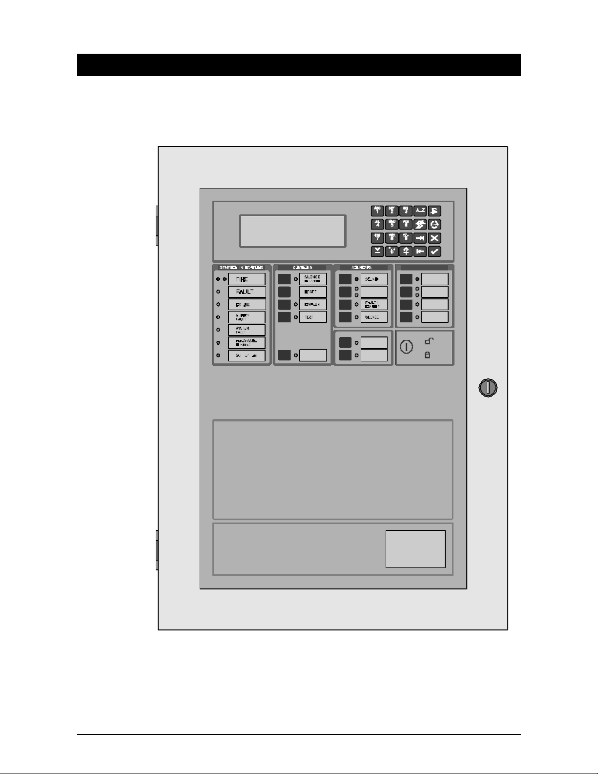
A view of the front of a typical FP2000 Series Fire panel is shown in Figure 1 below.
Figure 1: Fire Panel Front View
ANEL OPERATION
In order to describe the operation of a FP 2000 series fire panel, the front panel has been
divided into two sections, these being:
• LED indicators and controls
• LCD and keypad
10 Reference Guide
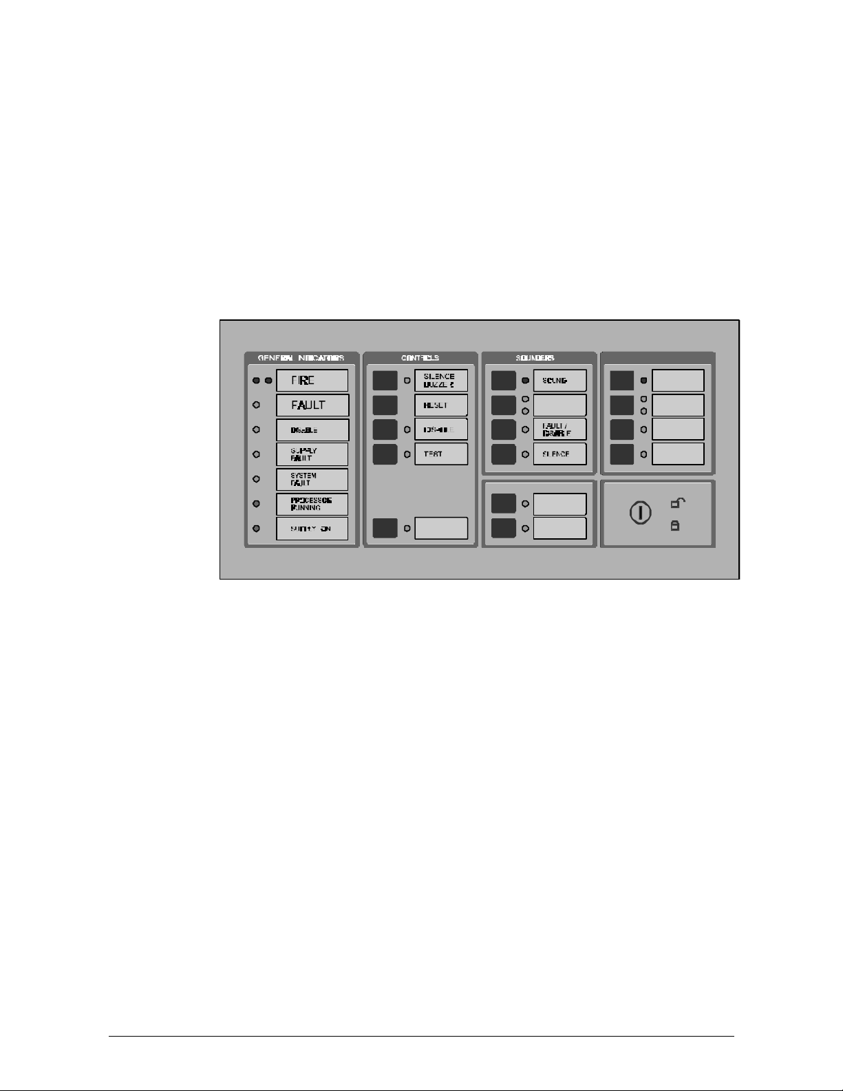
Led indications and controls
The LED Indications and controls can further be broken down into:
• General indicators
• Controls
• Sounders
• Fire Brigade
• Enable/Disable keyswitch
• Zone indicators
Figure 2: General Indications and Controls
General indicators
COMMON FIRE
Two red LED's indicate that a fire has been detected.
COMMON FAULT
One or more of the follow ing may cause a common fault:
• Zone fault
• Supply fault
• Processor fault
• Sounder fault
• Fire Brigade fault
• Any test mode
• Any disable mode
Reference Guide 11

COMMON DISABLE
A yellow LED indicates that one or more of the following have been disabled:
• Devices on the loop
• Zone
• Sounders
• Fire Brigade
SUPPLY FAULT
A yellow LED will illuminate for:
• Mains failure
• Battery disconnect or not charging
SYSTEM FAULT
A yellow LED indicates that a system fault has occurred. A system failure can be one or
more of:
• Tamper switch
• Service switch
• Logic error
• Memory lock
• No checksums calculated
• Hardware test fault
• Fireman’s panel down
• Repeater down
• Panel down
• Global repeater down
• Input fault
• Output fault
• Configuration fault
• Checksum fault
• Protected memory overwritten
• Time date wrong
• Access fault
• FEP fault
• Watchdog time -out
PROCESSOR RUNNING
A flashing green LED indicates normal operation.
SUPPLY ON
A green LED indicates that the system is receiving 24V power.
12 Reference Guide

Controls
SILENCE BUZZER (Keyswitch Enabled or Disabled)
The internal panel buzzer is activated for any new condition. The buzzer will be
continuous for a fire alarm condition, intermittent for a fault warning and slow intermittent
for a condition warning.
The buzzer is silenced by pressing the Silence Buzzer Key. The yellow silence buzzer
LED will illuminate to indicate that the buzzer has been silenced.
RESET (Keyswitch Enabled)
This pushbutton will reset the fire panel.
DISABLE (Keyswitch Enabled)
This pushbutton calls up the Disable Menu (see Page 173). The yellow LED will indicate if
anything is disabled.
TEST (Keyswitch Enabled)
This pushbutton calls up the Test Menu (see Page 160). The yellow LED under General
Indicators will illuminate if the panel is put into a test mode.
Sounders
SOUND
Depends on operation selected by bits 5 and 6 of DIP switch on HOST PSU board. ( *See
Appendix B of the FP2000 Installation and Commissioning Manual: LKFP2003). A red
LED indicates that the sounders have been activated.
DELAY ON/OFF
The programmed Sounder Delay ( see Output Delays, Page 62) may be toggled ON or
OFF. Two LEDs indicate the state.
Depends also on operation selected by bits 5 and 6 of DIP switch on HOST PSU board.
(*See Appendix B of the FP2000 Installation and Commissioning Manual: LKFP2003 ).
FAULT/DISABLE (Keyswitch Enabled)
The Sounder Fault/Disable pushbutton allows the sounders to be disabled. The
associated LED indicates that the sounders have been disabled or that a sounder fault is
present.
The sounder fault can be:
• Sounder circuit open circuit
• Sounder circuit short circuit
• Bell fuse failure
Reference Guide 13

SILENCE (Keyswitch Enabled)
Depends on operation selected by bits 5 and 6 of DIP switch on HOST PSU board. ( *See
Appendix B of the FP2000 Installation and Commissioning Manual: LKFP2003). A yellow
LED indicates that the sounders have been silenced.
Fire brigade
SIGNAL (Keyswitch Enabled)
Depends on operation selected by bits 5 and 6 of DIP switch on HOST PSU board. ( *See
Appendix B of the FP2000 Installation and Commissioning Manual: LKFP2003). A red
LED will indicate that the signal has been activated.
DELAY ON/OFF
The programmed Fire Brigade Signal Delay ( see Output Delays, Page 60) may be
toggled ON or OFF. Two LEDs indicate the state.
Depends also on operation selected by bits 5 and 6 of DIP switch on HOST PSU board.
FAULT/DISABLE (Keyswitch Enabled)
✍
The Fire Brigade output may be disabled by using this pushbutton. When the signal is
disabled, then the disable LED will be illuminated.
The Fir e Brigade circuit is supervised. The Fire Brigade fault LED will flash when a fault is
detected in the circuit.
STOP FIRE BRIGADE (Keyswitch Enabled)
Depends on operation selected by bits 5 and 6 of DIP switch on HOST PSU board. ( *See
Appendix B of the FP2000 Installation and Commissioning Manual: LKFP2003). A yellow
LED will indicate that the Fire Brigade signal has been deactivated.
ENABLE/DISABLE KEYSWITCH
An Enable/Disable keyswitch is provided to either allow or prevent operation of the fire
panel controls. The Silence Buzzer and Test keys will operate with the keyswitch in any
position.
The different Sounder and Fire Brigade keys' operation depend on the operation selected
by bits 5 and 6 of the DIP switch on the HOST PSU board. (*See Appendix B of the
FP2000 Installation and Commissioning Manual: LKFP2003).
Level 1 for Disable and level 2 for Enable must not be confused with access levels 1 and
2. There is no relation between the Enable/Disable keyswitch and the allocated access
levels.
14 Reference Guide

Other
PANEL
This button is used by global and local repeaters for panel emulation. Emulation mode is
activated with a global repeater by pressing the Panel key, then entering the number of
the panel to be emulated, and Enter ( ).
To stop emulation, the Panel key is pressed and then "0" and Enter ( ).
When a global repeater is emulating a panel it is not necessary to stop emulation before
emulating another panel. The global repeater will automatically stop the emulation before
trying to emulate another panel.
With a local repeater, pressing the Panel key will start emulation of the panel. If the panel
is already emulated, pressing the Panel key will stop emulation.
The yellow LED indicates whether a panel is emulated or not.
ALL
Used by the global repeater panel to send a command to all the panels the global
repeater is communicating with. The yellow LED indicates that the key was pressed,
meaning that the following command button to be pressed will be sent to all the relevant
panels.
THIRD SOURCE TEST
This key tests the third source battery when the panel is powered on. Pressing the key
will sound the buzzer.
Zone indicators
Each zone has two indicators. A red LED indicates a fire and a yellow LED indicates a
fault, disablement or test. The zone fault LED will flash for a fault condition and be steady
on for disablement or test. The zones are numbered from the top left, from left to right.
Figure 3: Zone Fire and Fault Indication
Reference Guide 15
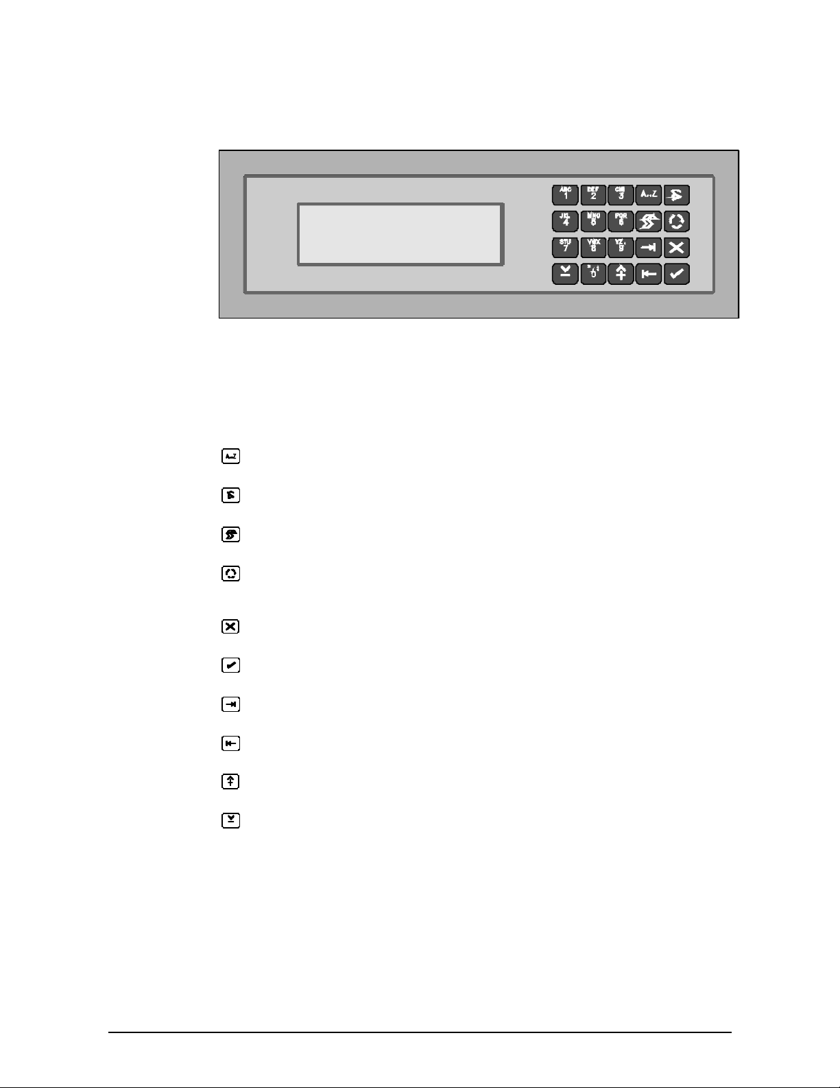
LCD and Keypad
Figure 4: LCD and Keypa d
The operation of the display is detailed in Chapter 3.
KEYPAD
The keypad consists of 20 keys, 10 of which are alphanumeric keys. The remaining 10
are assigned various functions as detailed below:
Alpha selection when using any of the 10 alphanumeric keys.
Used to display the latest alarm at any time.
Print screen function to print any screen to the internal or external printers.
Scroll key used to move between Alarm, Fault and Conditions, as well as to
view additional information when the "M ORE" prompt appears on the LCD.
Exit to previous menu
Enter or confirm
Move to the next field in the display
Move to the previous field in the display
Increment
Decrement
16 Reference Guide

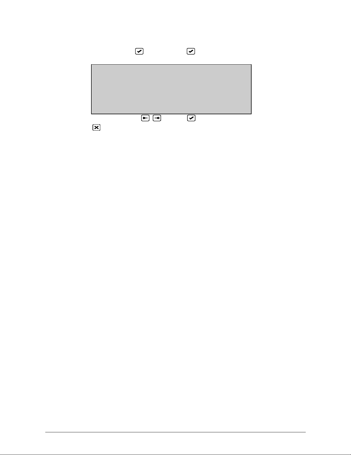
Alarm line
EN54 Part 2 requires that the number of alarms, faults and conditions be displayed at all
times on the LCD screen. In the FP2000 product range this is accomplished by means of
the bottom line of the LCD Screen (called the ALARM LINE) as hig hlighted below:
The system status and mode is also summarised in the bottom right hand corner of the
alarm line.
The explanation of the initials used for this is as follows:
System Status System Mode
Idle I Day Mode D
Powerup P Night Mode N
Scanning S Security Zones On Z
Autosetup A Security Zones Off O
Sensor test T
3. LCD S
SYSTEM STATUS Fri 12/01/99 09:17:37
Scanning Day Mode Zones On
Alarms: 0 Faults: 0 Cond.: 0 P: 1 SDZ
CREEN OPERATION
E
For example
SDZ - Scanning, Day Mode, Zones On
SDO - Scanning, Day Mode, Zones Off
SNZ - Scanning, Night Mode, Zones On
etc.
If the panel is assigned a number, the number is displayed as part of the alarm line:
P - Fire panel
G - Global repeater or master panel
L - Local repeater panel
For example
P: 1 - Fire panel number 1
G: 1 - Global repeater panel number 1
L: 1/1 - Local repeater panel number 1 of fire panel 1
Reference Guide 17

Valid entries line
The second line from the bottom displays the valid keypad entries for the displayed menu,
as well as messages for the operator.
The following table describes these characters and messages and their relation to the
keypad:
MENU
KEYPAD DESCRIPTION
DISPLAY
<
>
∧
∨
E
X
0..9 0..9
A..z
Numeric
Alpha
More
Invalid Key -
Memory
Locked
Open Memory
Lock
Not in Service
Mode
No Access
0..9
a..z
A..Z
other1
-
-
-
-
Move backward between fields
Move forward between fields
i) Select available options – forward
ii) Increment numeric field values
iii) Move forward within a text line
i) Select available options – backward
ii) Decrement numeric field values
iii) Move backward within a text line
i) Start entry into FP2000 menu system - from the SYSTEM STATUS
Menu (highest level menu)
ii) Confirm selection
iii) Confirm field entry
i) Return to higher level menu
ii) Cancel changed field values
i) Selection of sub-menus
ii) Changing of numeric field value
Changing of test line (string) text - numeric characters 0 to 9, small capital
letters of alphabet and other ASCII characters1.
Indicates the keypad mode - pressing the [A..Z] key toggles between
numeric and alpha characters.
Indicates the keypad mode - pressing the [A..Z] key toggles between
numeric and alpha characters.
Toggle between different screens of a particular menu.
The pressed key has no meaning with regard to the displayed menu.
The Me mory Lock Switch on the Host PCB must be in the OPEN position
for the change to be accepted.
Place the Memory Lock Switch on the Host PCB in the OPEN position.
The Service Switch on the Host PCB must be in the OPEN position for the
operation to be executed.
i) A higher access level is needed to enter the selected menu
ii) While in the menu system, in other words access was granted, access
is disabled via a communication port. This is typically caused by the
up-/download software via a serial port (SER1/2).
1
Keypad characters: 0 to 9
✍
a to z
A to Z
.=*,;~#$%^&`{}[]()<>:"/
space
18 Reference Guide

Status line
The status line is the third line from the bottom (see highlighted line) and the system
status, as summarised in the alarm line, is displayed in full. Note that the system status
line is not present in all menus:
SYSTEM STATUS Fri 12/01/99 09:17:37
Scanning Day Mode Zones On
E
Alarms: 0 Faults: 0 Cond.: 0 P: 1 SDZ
System status menu
Under normal operating conditions the LCD Screen shows the System Status Menu as
given below:
SYSTEM STATUS Fri 12/01/99 09:17:37
Scanning Day Mode Zones On
E
Alarms: 0 Faults: 0 Cond.: 0 P: 1 SDZ
Reference Guide 19

4. P
ROGRAMMING MENUS
Access to main menu
Main Menu obtained from the System Status Screen after entering an access code.
If the fire panel is currently displaying alarms, faults, or conditions on the screen, then
press to obtain the System Status Screen.
SYSTEM STATUS Fri 12/01/99 09:17:37
Scanning Day Mode Zones On
E
Alarms: 0 Faults: 0 Cond.: 0 P: 1 SDZ
Press to obtain the access code prompt.
Enter Access Code:
0. .9, <>, E, X
Alarms: 0 Faults: 0 Cond.: 0 P: 1 SDZ
Enter a one to four digit code and press .
The Main Menu will be displayed, provided one of six correct codes has been entered.
Different codes may have different access levels . This means that some facilities may
not be available to users with a code of lower access level.
*See Access Menu, Page 49
20 Reference Guide
Main menu
(SYSTEM STATUS, , CORRECT CODE, )
MAIN MENU
1 System 2 Devices
3 Input/Output 4 Events
5 Maintenance 6 Test/Disable
0. .9, <>, E, X
Alarms: 0 Faults: 0 Cond.: 0 P: 1 SDZ
Select number or use and press
Return to System Status *See Chapter 3.
1 System Menus Page 23
2 Device Menus Page 68
3 Input, Output and Logic
Page 97
4 Event Log Page 137
5 Maintenance Menus Page 142
6 Test and Disable Functions Page 160 (Test menu)
Page 173 (Disable Menu)
All data of the fire panel may be viewed and/or changed by persons authorised to do so.
In order to view any screen requires the correct access code(s). In order to change data,
the user requires both the correct access code and the memory must be unlocked. The
memory lock switch is located on the Host CPU board and thus access is required within
the cabinet in order to change data.
The Main Menu provides a logical subdivision of the fire panel data and facilities.
• System - The viewing/programming of the fire panel internal system. Items such as
the serial ports, RAM memory, operation, date/time and timings are accessed.
• Devices - The viewing/programming of all facilities of the devices connected to the
loops of the fire panel. This includes the zoning and statistics of each device as well
as graphic screens.
• Input/Output - The definition of inputs and outputs, as well as the logic defining the
operation of the fire panel according to input/output. Inputs and outputs are derived
from the internal system, I/O devices on the loop, and network.
• Events - The examination and selective printing of the event log. The event log is also
cleared in this menu.
• Maintenance - The facilities provided in order to completely maintain the fire panel
system and the devices on the loop. This includes a host of reporting facilities.
Reference Guide 21

• Test/Disable - Zones and individual devices can be selectively tested and disabled.
Test features include one-man test of zones and soak test of individual devices. The
Test and Disable Menus are not directly available from the Main Menu, but are
accessed by using the Test and Disable keys on the front panel. These menus do not
require any access code, but do r equire that the enable/disable keyswitch is enabled.
Selecting Test/Disable from the Main Menu causes a prompt to operate the desired
keyswitch.
22 Reference Guide

System menu
(MAIN MENU, 1, )
SYSTEM MENU
1 Configuration 2 Access
3 Clear Site Data 4 Set Default
5 Set Times 6 Restart
0. .9, <>, E, X
Alarms: 0 Faults: 0 Cond.: 0 P: 1 SDZ
Select number or use and press
The System Menus are used to configure and display the internal operation of the fire
panel. That is, all parameters other than the loop devices and input output programming.
The menu selections are:
1 Configuration Page 24
Hardware configuration
Memory allocation
Panel ID
Communication including port, serial, printer and network set-ups
Return to Main Menu Page 21
2 Access Page 49
Set user access codes
Set access levels of the menus
3 Clear Site Data Page 52
Clear the site programmable data
4 Set Default Page 55
Set the site programmable data to default values
5 Set Times
Fire panel date and time
Sounder and Fire Brigade Delay
Sounder and Fire Brigade Delay on/off times
Zone on and off times
Day/night mode times
Page 58
6 Restart Page 67
The fire panel will perform a cold start as if it had been switched off and
then on. Restart will only operate if the Memory Lock/Unlock switch located
on the Host CPU board is in the LOCK position.
Reference Guide 23

Configuration menu
(SYSTEM MENU, 1, )
CONFIGURATION MENU
1 Hardware 2 Allocation
3 ID 4 Communication
0. .9, <>, E, X
Alarms: 0 Faults: 0 Cond.: 0 P: 1 SDZ
Select number or use and press
Return to System Menu Page 23
1 Hardware Page 25
View the fire panel internal configuration, software version, ports and PCB's.
2 Allocation Page 29
Memory allocation for field devices, I/O and logic, text, and event buffer
3 Panel ID
Set the ID number of the fire panel
Page 31
4 Communication Page 33
Port setup
Network
Modem
Current loop devices
24 Reference Guide

Hardware configuration 1
(CONFIGURATION, 1, )
Version: 5.00NKF 23.05.99/5.00-8 29.05.99
Ports: 5 Zones : 112 Loops : 2A
Unlocked : 256k Locked RAM : 128k
Relays Sup.Rel. Inputs
Backpanel: 4 4 8
Frontpanel: 0 0 0
more X
Alarms: 0 Faults: 0 Cond.: 0 P: 1 SDZ
Press [More ] to view Hardware Configuration 2 Page 27
Return to Configuration Menu Page 24
This display and the Hardware Configuration 2 display show the hardware configuration
of the fire panel. The particular configura tion will be determined by the model number of
the FP2000 as well as any optional boards that may have been installed.
The screen will show:
Version -
The version number and the compilation date of the installed HOST and FEP software.
Ports -
The number of ports installed.
The standard ports are:
FEP Port (not accessible to the user)
Current Loop (for fireman’s panels)
Ser1 RS232 Serial port 1
Ser2 RS232 Serial port 2
ARC 1 Arcnet port 1
Zones -
The number of displayable zones equipped.
Loops -
The number of loops equipped and whether the loop driver boards are connected in
Class A or Class B configuration. Each loop board accommodates two Class A loops or
four Class B loops.
Unlocked RAM -
The amount of RAM installed that is not controlled by the memory lock switch.
Locked RAM -
The amount of RAM installed that is controlled by the memory lock switch. Locked RAM
is used for site data.
*See Memory Allocation, Page 29 for more information relating to memory size.
Reference Guide 25

Backpanel and Frontpanel Input and Output Equipped -
The FP2000 contains, as standard, relays and input ports. The back panel refers to the
boards plugged into the FEP section in the base of the fire panel. The front panel refers
to the boards plugged into the HOST section in the door of the fire panel. The HOST
section contains two layers of board plug -in positions.
The standard equipped I/O is:
• Four Inputs IN1 - IN4 located on the FEP board These inputs are freely programmable by the user.
• Sounder board:
- Four monitored relays (OUT1 - OUT4)
- Four unmonitored relays (OUT5 - OUT8)
The monitored relays have dedicated functions:
OUT1 - Sounder
OUT2 - Fire Brigade
OUT3 - Fire Protection
OUT4 - Fault Routing
- Four supervised inputs (IN5 - IN8)
IN8 is a general programmable input, but the others have dedicated functions:
IN5 - Fire brigade feedback (EN54-mode only)
IN6 - Fire protection fault (EN54-mode only)
IN7 - Fault routing fault (EN54-mode only)
All relays are programmable by means of the I/O programming menus, but care should
be taken when programming the dedicated relays above.
Any additional optional I/O that is equipped within the FP2000 will be shown on this
screen.
*See I/O Menus, Page 97 for the programming of Inputs and Outputs.
26 Reference Guide

Hardware configuration 2
(CONFIGURATION 1, )
HARDWARE CONFIGURATION
Host :DEN ZON ARC . . . . . . . . . . . . . . .
PSH . . . . . . . . . . . . . . . . . . . . .
FEP :LPA REL VDS . . . . . . . . . . . . . . .
ADD :FEP HST KBD LCD PSF . . . . . . . . .
more <>, E, X
Alarms: 0 Faults: 0 Cond.: 0 P: 1 SDZ
Press [More ] to view Hardware Configuration 1 Page 25
Return to Configuration Menu Page 24
Select the PC Board code using the cursor
View additional details of the selected PC Board
This menu is used to display the details of the printed circuit boards (PC Boards) installed
in the FP2000 system. The PC Board summary is shown in three sections:
1 Addressable boards located in the Host CPU (front panel) section.
2 Addressable boards located in the FEP (back panel) section.
3 Additional non -addressable boards located in both the Host and FEP system
Reference Guide 27
Board information
(CONFIGURATION 2, or, , )
BOARD INFORMATION
Addr. :17 Sup1:passive Inp5:passive
ID :20 Sup2:passive Inp6:passive
Type :VDS Sup3:passive Inp7:passive
Sup4:passive Inp8:passive
X
Alarms: 0 Faults: 0 Cond.: 0 P: 1 SDZ
Return to Hardware Configuration Page 25
This includes:
• Board description
• Actual board address
The board address is used in certain I/O programming
The board description and address in a two loop, 16 zone FP2000 is given below. Note
that board addresses are changed automatically when additional PC boards are added or
removed. When more than one loop driver or zone board is present in a system, then
each one of these boards assumes a unique address.
PC Board Description Address
DEN Common Display (EN Type) 0
ZON 16 Way Zone Board 1
PSH Host Power Supply 8
LPA 2 Loop Class A Driver 16
VDS Common Input/Output 18
FEP Front End Processor 24
HST Host CPU 25
KBD Keypad 26
LCD Liquid Crystal Display 27
PSF FEP Power Supply 28
28 Reference Guide

Memory allocation 1
(CONFIGURATION, 2, )
MEMORY ALLOCATION Free unlocked :175238
Free locked :84042
Logic :600 Input Text :40
Inputs :200 Output Text :40
Outputs :200 Zone Text :40
Events :999 Area Text :40
more 0. .9, ^V, <>, E, X
Alarms: 0 Faults: 0 Cond.: 0 P: 1 SDZ
Press [More ] to view Memory Allocation 2 Page 29
Return to Configuration Menu Page 24
Select item to be changed
or 0..9 change data in item (Unlock memory!)
Confirm change
Changing memory allocation will clear all existing programmed data from memory!
✍
The user must reprogram all site data after changing any items in memory allocation.
The random access memory (RAM) of the fire panel is partitioned for different types of
data. Some of this data is contained within locked memory; other data is in unlocked
memory.
The default memory allocation for the FP2000 is shown. Further information is obtained
by using [More ] (Page 30). The default memory allocation should be correct for most
applications and should only be changed if the user has particular requirements that
exceed the parameters given.
The amount of free locked and unlocked memory is dynamically displayed on the screen
as allocations are increased or decreased.
!
W hen exiting from this menu, the user is prompted as to whether the allocation is to be
saved or not. This prompt will occur even if no parameters have been changed. If the
allocation is saved then all RAM is cleared and the fire panel must be reprogrammed.
Press for no save
Press for YES and then in order to save the allocation (Unlock memory!)
Reference Guide 29

Memory allocation 2
(CONFIGURATION, 2, , )
MEMORY ALLOCATION
Loop Devices Text Loop Devices Text
1 128 80 5 0 0
2 128 80 6 0 0
3 0 0 7 0 0
4 0 0 8 0 0
more X
Alarms: 0 Faults: 0 Cond.: 0 P: 1 SDZ
Press [More ] to view Memory Allocation 1 Page 29
Return to Configuration Menu Page 24
The amount of RAM memory allocated to field devices on the loops is viewed with this
screen. Provision is made for 80 characters of user text for each device. It is not possible
to change the amount of memory allocated. Allowance is always made for 126 or 128
devices per loop irrespective of the number of devices actually installed. The amount of
memory used is dependent only on the number of loops equipped within the fire panel.
!
When exiting from this menu, the user is prompted as to whether the allocation is to be
saved or not. This prompt will occur even if no parameters have been changed. If the
allocation is saved then all RAM is cleared and the fire panel must be reprogrammed.
Press for no save
Press for YES and then in order to save the allocation (Unlock memory!)
30 Reference Guide

Panel ID
(CONFIGURATION, 3, )
IDENTIFICATION
Change of Node ID Clears Eventbuffer!
Node : 1 / 0 Max. Config.:15/15
Panel : 1
0. . 9, ^V, E, X
Alarms: 0 Faults: 0 Cond.: 0 P: 1 SDZ
Return to Configuration Menu Page 24
Select item to be changed
or 0..9 change data in item (Unlock memory!)
Confirm change
For Panel ID Text Fields (2 lines x 40 characters):
Use to obtain the text line to be changed
Press (Unlock memory!)
Use to toggle between alpha and numeric text
Press the alpha/numeric button required
Use to move the cursor within the line
Press when completed
Default:
ID: 0/0
Panel: 0
Max. Config.: 15/15
Each FP2000 fire panel, as well as global repeaters and local repeaters in a network
system, can be uniquely identified by means of the panel ID. The panel ID is used for the
upload/download of data via the serial ports, as well as information transfer on the
network. In addition to the panel ID, two lines of user text can be assigned t o each fire
panel or repeater. The user text is displayed on the System Status Screen and for the
logging of all system (general) fault warnings of the panel.
The Panel ID consists of two digits: fire panel number/repeater number (p/r).
For fire panels the repeater number is always Ø
e.g.: 0/0 - fire panel Ø
12/0 - fire panel 12
For global repeaters (network systems only) the fire panel number is zero, and the
repeater number defines the global repeater
e.g.: 0/1 - global repeater number 1
0/3 - global r epeater number 3
For local repeaters attached to a particular fire panel on the network, the fire panel
number and the repeater number defines the repeater
e.g.: 1/3 - repeater 3 of fire panel 1
3/1 - repeater 1 of fire panel 3
Reference Guide 31

The field "Panel" confirms the fire panel number. The panel ID is also shown on line 8 of
the display: P:p. For global repeaters the word "Panel" becomes "G -Repeater" and line 8
displays G:r. For local repeaters the display is "repeater" and L:p/r is displayed on line 8.
The field Max. Config. : Panel/repeater show the maximum number of panels and
repeaters, local or global that can be configured. The
options are: 7/31
15/15
31/7
When transferring data from a computer to the fire panel, the fire panel ID of the data file
must match the fire panel ID.
When setup as a Global Repeater, additional Universal Node settings are possible:
un-n for a Universal Node on the Setup/NET1/NET2 Port
un-m for a Universal Node on the Modem Port
• If set to 0/0, the Universal Node ID will automatically assume the ID of the connected
PC or Panel.
• If set to 0/x (x = valid repeater number) then the Universal Node functions will only
work if the connected PC or Panel will have the same ID.
32 Reference Guide

Communication menu
(CONFIGURATION, 4, )
COMMUNICATION MENU
1 Port Setup 1 Network
3 Modem 4 CL Devices
0. . 9, <>, E, X
Alarms: 0 Faults: 0 Cond.: 0 P: 1 SDZ
Select number or use and press
Return to Configuration Menu Page 24
1 Port Setup Page 34
Set the communication ports to the functions required.
2 Network Page 37
Panels
Local Repeaters
Global Repeaters
3 Modem Page 41
Alarm Report
Maintenance
Setup
4 Current Loop Devices
Set up the panel number and mode of operation.
Page 48
Reference Guide 33

Port setup
(COMMUNICATION, 1, )
PORT SETUP
Port :INT Baudrate :9600
Allocation :FEP Protocol :8, 1, n
^V, <>, E, X
Alarms: 0 Faults: 0 Cond.: 0 P: 1 SDZ
Return to Communication Menu Page 33
Select item to be changed
Change data in the item (Unlock memory!)
Confirm change
This menu is used to set the function and, if applicable, the data rate (Baudrate) of the
physical communication ports.
1. Select the required port (only installed ports can be selected):
INT
CL The current loop port used for local fireman’s panels
SER1
SER2
ARC1 Arcnet network board 1 (optional).
2. Select the function to be assigned to the port using the allocation field:
None The selected port has no function. This is the default
NET1 The FP2000 will support two networks simultaneously.
NET2 All communication assigned to NET1 (see Network
Ev. pri Set the selected port as an event printer. All events of
Not available to the user.
only.
The Baudrate must be 600.
The standard serial ports provided on the FP2000 fire
panel.
setting with the exception of the CRL and FEP ports that
have predefined functions.
Menu, Page 4-18) will be sent to the ports allocated to
the NET1 function. Similarly all communication assigned
to NET2 will be sent via the NET2 port. Generally the
ARC1 port will be set to NET1. In the case of a graphic
system connected to the serial port (SER1, say) the
SER1 port is assigned the function NET1, ARC1, SER12 are the only ports that support NET1 and NET2.
the fire panel are sent to the port when they occur. Any
information that is manually sent to Ev.Pri by the user
will also be printed. The fire panel will give a fault if the
device connected to the event printer port is not
connected or not ready (e.g. paper out).
34 Reference Guide

3. Select the Baudrate for the serial ports (default 9600)
Rp.Pri Set the selected port as a report printer. The report
printer port is used to manually sent report to a device
such as a printer or laptop computer. It is primarily used
for selected printing of the event buffer, test reports and
such. No fault is given if a report printer is off line or not
plugged in. Thus, a report printer can be removed at any
time. Reports are held in a buffer when the device
connected to the port is not on -line. The type of printer
(e.g. internal) can be defined.
VDU This function operates in the same manner as Rp.Pri
above, except that the report is halted every 20 lines
(one VDU screen). Pressing any character on the VDU
device will allow the report to be continued for a further
20 lines. This function is particularly useful for viewing
reports on the screen of a laptop computer. Only the
serial ports support VDU.
EMU The port is set to emulation mode. Only the serial ports
support EMU. This allows the fire panel to be operated
remotely by means of a computer. The entire fire panel
front panel keyboard and display is accessible via the
serial port in this mode. Special software (PC2000
series) is required at the computer to operate in
emulation mode.
CL Device This is the default function for the current loop port. It is
used to communicate to fireman’s panels connected to
the current loop port. This function should not be
assigned to any other port.
Setup Allows remote upload and download of site via the serial
port. This function is used to program site data into the
fire panel. Upload/download software is required at the
computer. Only the serial ports support Setup.
FEP The FEP function is used for the INT port only.
Modem This function assigns one of the serial ports as an
300
600
1200
2400
4800
9600 Default
19200
38400
interface to a modem.
Reference Guide 35

Select the mode of operation for the ARCNET ports:
4. The protocol of the serial ports is fixed: Eight data bits, one stop bit, and no parity
Example:
To activate the built-in printer as an event printer: Ser2 must be allocated to Ev.Pri.
Bus
Dual Bus
Ring Half Duplex
Ring Half Duplex (Master)
Ring Full Duplex
Only for CE-FP -344-x
36 Reference Guide

Network menu
(COMMUNICATION, 2, )
NETWORK MENU
1 Panels 2 L-Repeaters
3 G-Repeaters
0. . 9, <>, E, X
Alarms: 0 Faults: 0 Cond.: 0 P: 1 SDZ
Select number or use and press
Return to Communication Menu Page 33
1 Panels Page 38
Define other fire panels on the network that will communicate with this fire panel.
2 L-Repeaters Page 39
Define local repeaters on the network that will communicate with this fire panel.
3 G-Repeaters Page 40
Define the global repeaters that will communicate with the fire panel on the network.
Reference Guide 37

Panels
(NETWORK, 1, )
PANELS
Panel No. :1
Status :dis
0. . 9, ^V, <>, E, X
Alarms: 0 Faults: 0 Cond.: 0 P: 1 SDZ
Return to Network Menu Page 37
or 0..9 to select panel number
Move to status field
Toggle dis/NET1 check/NET2 check/ NET1 no check/NET2 no check (Unlock
memory!)
Confirm entry
The fire panels that will communicate with this FP2000 fire panel on the network must be
assigned.
Fire panels that are assigned to the network will be checked for communication on the
system. If a panel is assigned to "NET1/2 check", a fault warning will be displayed in the
event of a failure, but if assigned to "NET1/2 no check" the failure will only be an action
logged in the event buffer.
Each fire panel on the system must have the correct ID set (see Page 31).
✍
The fire panel that is being programmed must be set at disable, i.e. a fire panel does not
check itself: assign only other fire panels.
38 Reference Guide

Local repeaters
(NETWORK, 2, )
LOCAL REPEATERS
L-Repeater No. :1
Status :dis
^V, <>, E, X
Alarms: 0 Faults: 1 Cond.: 0 P: 1 SDZ
r Return to Network Menu Page 37
or 0..9 to select repeater number
Move to status field
Toggle dis/NET1 check/NET2 check/NET1 no check/NET2 no check (Unlock
memory!)
Confirm entry
The local repeater that will communicate with this FP2000 panel on the network, must be
assigned.
Local repeaters that are assigned to the network will be checked for communication on
the system. If a local repeater is assigned to "NET1/2 check", a fault warning will be
displayed in the event of a failure, but if assigned to "NET1/2 no check", the failure will
only be an action logged in the event buffer.
Reference Guide 39

Global repeaters
(NETWORK, 3, )
GLOBAL REPEATERS
G-Repeater No. :1
Status :dis
^V, <>, E, X
Alarms: 0 Faults: 1 Cond.: 0 P: 1 FDZ
Return to Network Menu Page 37
or 0..9 to select master number
Move to status field
Toggle NET1 check/NET2 check/NET1 no check/NET2 no check (Unlock memory!)
Confirm entry
The global repeaters that will communicate with this FP2000 panel on the network, must
be assigned.
Global r epeaters that are assigned to the network will be checked for communication on
the system. If a global repeater is assigned to "NET1/2 check", a fault warning will be
displayed in the event of a failure, but if assigned to "NET1/2 no check", the failure wi ll
only be an action logged in the event buffer.
40 Reference Guide

Modem menu
(COMMUNICATION, 3, )
MODEM MENU
1 Alarm Report 2 Maintenance
3 Setup
0. . 9, <>, E, X
Alarms: 0 Faults: 1 Cond.: 0 P: 1 SDZ
Select number or use and press
1 Alarm Report Page 42
Set up the conditions for alarm reporting and the destination telephone numbers.
2 Maintenance Page 44
Enable or disable of remote maintenance.
Return to Communication Menu Page 33
3 Setup
Modem setup commands.
Page 45
Reference Guide 41

Modem alarm report 1
(MODEM, 1, )
MODEM ALARM REPORT
Tel. No. Fire Fault Cond. Disc.
dis dis dis rem
dis dis dis local
dis dis dis local
dis dis dis local
more Numeric, A. . z, ^V, <>, E, X
Alarms: 0 Faults: 1 Cond.: 0 P: 1 SDZ
Return to Modem Menu Page 41
Select field to be changed
To change selection (Unlock memory!)
Confirm entry
For telephone numbers:
Use to move to the required telephone number line
Use to toggle between alpha and numeric text when necessary and press the
required button
Use to move the cursor within the line
Press when complete (Unlock memory!)
Press to go to Modem Alarm Report 2 Page 43
The telephone numbers whereto alarm reports must be sent and the conditions that
causes the reports to be sent, are set up with this menu.
The device that has to disconnect can be selected in the last column:
rem: The "remote device" (PC) has to disconnect.
local: The panel/global repeater will disconnect automatically when the message
has been broadcasted.
42 Reference Guide

Modem alarm report 2
(MODEM ALARM REPORT 1, )
MODEM ALARM REPORT
Fire Delay :60 s Report :dis
Fault Delay :60 s Test Call :dis
Cond. Delay :60 s Test Line :dis
more 0. . 9, ^V, <>, E, X
Alarms: 0 Faults: 1 Cond.: 0 P: 1 SDZ
Return to Modem Menu Page 41
Select field to be ch anged
To change selection (Unlock memory!)
Confirm entry
Press to go back to Modem Alarm Report 1 Page 42
Fire, Fault and Cond. Delay:
Delays reporting to control station. If the panel gets reset before the delay has elapsed,
no alarm/fault condition will be reported. The shortest delay will start the reporting to the
central station and will report all pending alarms/faults/conditions.
Report:
Instead of report disabling by using the previous menu (Modem Alarm Report 1), this
menu supplies a quick disable mechanism. Disabling reports on this menu will disable all
reports regardless of the setup on the previous menu (Modem Alarm Report 1).
Test Call:
This menu enables a test call at every maintenan ce time.
Test Line:
This menu enables a line test with hardware test, manually or every hour automatically.
Reference Guide 43

Modem maintenance
(MODEM, 2, )
MODEM MAINTENANCE
Maintenance :dis
Dial back :dis
^V, <>, E, X
Alarms: 0 Faults: 1 Cond.: 0 P: 1 SDZ
Return to Modem Menu Page 41
To change selection (Unlock memory!)
Confirm entry
Remote maintenance via the modem can be disabled while the modem interface is
operational.
When Dial Back is disabled, the dial back command from the remote location (PC) will be
ignored.
44 Reference Guide

Modem setup 1
(MODEM, 3, )
MODEM SETUP
Wait for Connection :60 s
Pause between Calls :60 s
Max. dialling attempts :99
more 0. . 9, ^V, <>, E, X
Alarms: 0 Faults: 1 Cond.: 0 P: 1 SDZ
Return to Modem Menu Page 41
Select field to be changed
To change selection (Unlock memory!)
Use 0..9 or To change field values
Confirm entry
Press to go to Modem Setup 2 Page 46
Set the modem time-outs and the maximum dialling attempts.
Reference Guide 45

Modem setup 2
(MODEM SETUP 1, )
MODEM SETUP
Init :AT&FØMØ\NØ\JØ\Q3&QØ
SØ=1&WØ
Dial :ATDWT
Escape :+++
more Numeric, A. . z, ^V, <>, E, X
Alarms: 0 Faults: 0 Cond.: 0 P: 1 SDZ
Return to Modem Menu Page 41
Select field to be changed
Use to toggle between alpha and numeric text when necessary and
press the required button
Press to confirm (Unlock memory!)
Press to go to Modem Setup 3 Page 47
Set up the modem command strings.
Refer to your Modem manual for detailed description of the commands:
Init: Initialisation string for modem
for US Robotics : AT& F1MØ L1&MØ&KØ
SØ=1&WØ
Fast link: AT&FØMØL1\NØ\JØ\Q3&QØ%CØ
SØ=1&WØ
Datasystems: AT&FØMØ\NØ\JØ\ Q3&QØ%CØ
SØ=1&WØ
Bausch : AT&F1MØL1&CØ
SØ=1&WØ
Dial: Dial prefix for modem
Escape: Escape sequence for modem
46 Reference Guide

Modem setup 3
(MODEM SETUP 2, )
MODEM SETUP
Hangup :ATHØ
Test :ATDWT,
ID :
more Numeric, A. . z, ^V, <>, E, X
Alarms: 0 Faults: 1 Cond.: 0 P: 1 SDZ
Return to Modem Menu Page 40
Select field to be changed
Use to toggle between alpha and numeric text when necessary and
press the required button
Press to confirm (Unlock memory!)
Press to go to Modem Setup 1 Page 45
Set up the modem command strings
Hangup: Puts the modem on hook
Test: Test string for line test
ID: A String to identify the modem to the maintenance programs.
Reference Guide 47

CL devices
(COMMUNICATION MENU, 5, )
CL DEVICES
Panel :0 Inputs :0
Mode :dis Outputs :0
0. . 9, ^V, <>, E, X
Alarms: 0 Faults: 1 Cond.: 0 P: 1 FDZ
Return to Communication Menu Page 33
Select field to be changed
Enter number 0..9 or to change panel field
Select mode
Confirm entry (Unlock memory!)
Current Loop Devices:
All fireman’s panels connected to the current loop of the FP2000 fire panel are enabled
with this menu. Each fireman’s panel must have a unique address (see FM800
Installation, Configuration & Detailed Operation Manual or FR800 Installation,
Configuration & Detailed Operation Manual . Fireman’s panels that are enabled are
checked for communication, and a fault warning will occur in the event of a failure.
Mode:
The fireman’s panel can be assigned as Zone, Device , I/O or Area. (See also CL Devices
Menu under Input/Output Menu, page 98).
Input and Output:
Display the number of inputs/outputs available on the fireman’s panel. (Communication
between the two systems must of course be established for the panel to acquire this
information.)
48 Reference Guide

Access menu
(SYSTEM MENU, 2, )
ACCESS MENU
1 Access Codes 2 Field Access
0. . 9, <>, E, X
Alarms: 0 Faults: 1 Cond.: 0 P: 1 SDZ
Select number or use and press
1 Access Codes Page 50
Examine or change user access codes and the access level of any these codes.
2 Field Access Page 51
Set the access level of individual menus. This allows selected menus to be excluded from
access codes that have lower access levels.
Return to System Menu Page 23
Reference Guide 49

Access codes
(ACCESS MENU, 1, )
ACCESS CODES
Access No. :1
Access Code :1
Access Level :1
0. . 9, ^V, <>, E, X
Alarms: 0 Faults: 1 Cond.: 0 P: 1 FDZ
*See also Page 51
Six access codes are allowed in order to use the menu screens viz. Access No 1 to
Access No 6. Each of these access numbers can be assigned a numeric code of 1-4
digits. Each access number 1-6 is also allocated an access level: 1-Low level; 2-High
level; Ø-No access.
Return to Access Menu Page 49
Select item to be changed
or 0..9 change data in item (Unlock memory!)
Confirm entry
The access number of the entry code used to gain access to the menus is logged in the
event buffer. After 3 unsuccessful attempts to gain access, an Access Fault messag e is
given.
Each menu screen of the FP2000 fire panel has an access level. Access numbers that
have an access level 1 cannot use any menus that are set to level 2. In addition, access
codes of level 1 cannot view the access codes of level 2 in this menu (Access Codes).
The message "NO ACCESS" is given in this case.
The default codes and levels are:
Access Number Access Code Access Level
1 1 2
2 2 1
3 3 1
4 4 1
5 5 1
6 6 1
50 Reference Guide

Field access
(ACCESS MENU, 2, )
*See also Page 50
Each menu can be assigned an access level: 1-Low level; 2-High level. Entry codes that
have an access level of 1 cannot use any menu that has an access level of 2. Menus that
are set to access level 1 can be used by all entry codes.
FIELD ACCESS
Field number :0
Access Level :1
0. . 9, ^V, <>, E, X
Alarms: 0 Faults: 1 Cond.: 0 P: 1 SDZ
Return to Access Menu Page 49
Select item to be changed
0..9 change data in item (Unlock memory!)
Confirm entry
The default of all menus is 1 except for this menu (Field Access), Set Times and
Allocation. Thus, as default, an access code of level 2 is required to change the level of
any menu. (The access levels of the mentioned menus can be changed to 1).
A field number defines each menu of the FP2000. ( *Refer to Appendix A for the field
number of each menu. )
The access level is set by first entering the field access number of the menu, and then
changing the access level number.
Reference Guide 51

Clear site data 1
(SYSTEM MENU, 3, )
CLEAR SITE DATA
1 Devices 2 Zones
3 Areas 4 Inputs
5 Outputs 6 System
7 Loops 8 Logic Table
more 0. . 9, <>, E, X
Alarms: 0 Faults: 1 Cond.: 0 P: 1 SDZ
Select number or use and press (Unlock memory!)
When prompted for confirmation:
For Devices select loop number or use and press
All other selections use for YES and press
Return to System Menu Page 23
*See also Set Default, Page 55
All or parts of the RAM memory can be cleared of data. Certain data is also pre-set as
shown below. The data blocks that can be cleared (initialised) are:
1 Devices – Select the loop number (for all loops)
The devices of the selected loop(s) are set to:
Status: Disabled
Type: None
Zone: Ø
Day level: 3
Soak test: Disabled
Test value: Ø
Contamination: Ø
Statistics: Cleared
2 Zones – All zones are set to:
Status: Enabled
Mode: Normal
Area: 0
Safe Zone: Disabled
On/Off: Disabled
Day/Night: Disabled
Sounder Delay: Disabled
Fire Brigade Delay: Disabled
3 Areas – All areas are set to:
Status: Enabled
Coincidence: Unlogged
Adjacent area 1-5: Ø
4 Inputs – All inputs are set to:
Type: None
52 Reference Guide

5 Outputs – All outputs are set to:
Type: None
6 System
Panel ID: Ø/ Ø
Port : INT - set to FEP; Baudrate 9600
CL - set to CL Device; Baudrate 600
SER1 - set to Setup; Baudrate 9600
SER2 - set to None; Baudrate 9600
Other ports - function: None
Network: Panels disabled
Repeaters disabled
Masters disabled
Access codes: *See Page 54
Field access: All menus have access level 1 except Field Access, Set
Times and Allocation have access level 2
Sounder/Fire Brigade Delay: 0 s
All times: 00h00
Sounder off time, Zones on
time and day mode time: Linked to none
7 Loops – loop data set to: Enabled
8 Logic table
All logic instructions are cleared and an “END” is placed in line 1.
Reference Guide 53

Clear site data 2
(CLEAR SITE DATA 1, )
CLEAR SITE DATA
1 Modem 2 CL Devices
3 All
more 0. . 9, <>, E, X
Alarms: 0 Faults: 1 Cond.: 0 P: 1 SDZ
Select number or use and press (Unlock memory!)
When prompted for confirmation:
For Devices select loop number or use and press
All other selections use for YES and press
Return to System Menu Page 23
*See also Set Default, Page 55
1 Modem
All times to Ø
Clear all telephone numbers
Clear all modem command strings
2 CL Devices
Disable all Fireman's panels
3 All
All of the above selections (1 -8 of the first menu and 1-2 of the second menu) cleared
simultaneously.
54 Reference Guide

Set default
(SYSTEM MENU, 4, )
SET DEFAULT
1 Devices 2 Zones
3 Area 4 System
5 Loops 6 Configuration
7 Logic table 8 Modem
0. . 9, <>, E, X
Alarms: 0 Faults: 1 Cond.: 0 P: 1 SDZ
Select number or use and press (Unlock memory!)
When prompted for confirmation:
For Devices select loop number or use and press
All other selections use for YES and press
Return to System Menu Page 23
*See also Clear Site Data, Page 52
Certain parameters of the site data can be set to default (predetermined) values. This is a
means of quick-programming the FP2000 fire panel. It is also useful to set default values
to various groups and then selectively change the items that do not correspond to the
default values. Default will only overwrite selected items and will not clear data that is not
affected by the default setting.
In general it is advisable to first clear the selected block using Clear Site Data, and then
set that block to default values.
!
Default Configuration (see 6 below) will clear all site data from memory and then partition
the memory. This should be done (if required) before any other default operation. (See
Memory Allocation, Page 29.)
The default blocks and their settings are:
1 Devices
Default will only affect devices that are being addressed on the loop(s) at that time
Status: Enabled
Type: Field type
Test value: 255
- Select loop number (Ø for all loops)
Reference Guide 55

2 Zones
The total number of zones equipped on the FP2000 fire panel are proportioned amongst
the total number of devices that can be addressed by the fire panel.
E.g.: 16 zone 2 loop fire panel
maximum number of devices = 2 x 128 = 256
zone distribution = 256 / 16 = 16
Loop 1/1 to Loop 1/16 is assigned zone 1
Loop 1/17 to Loop 1/32 is assigned zone 2 etc.
Loop 2/1 to Loop 2/16 is assigned zone 9 etc.
Loop 2/113 to Loop 2/128 is assigned zone 16
64 zone 4 loops (devices = 512)
zone distribution = 8 devices/zone
3 Areas
The sixteen areas are equally distributed amongst the zones that are equipped on the
FP2000 fire panel.
e.g.: 16 zone fire panel
Zone 1 = Area 1
Zone 2 = Area 2, etc.
64 zone fire panel
Zone 1-4 = Area 1
Zone 5-8 = Area 2, etc.
✍
4 System
Reserved
5 Loops
Enabled
6 Configuration
The memory is partitioned to the default configuration (see Memory Allocation, Page 29).
7 Logic
The logic table is set to a standard equation:
Input 1 = Output 1
Input 2 = Output 2, etc.
This equation is extended to the lower of:
- halve (see note) of the maximum number of logic lines allowed by the memory
allocation for logic
- the maximum number of inputs
- the maximum numbers of outputs
One equation comprises two logic lines. An allocation for logic of 300 would allow the
equation to be extended to: Input 150 = Output 150; provided that the number of inputs
and outputs are 150 or more.
56 Reference Guide

8 Modem: Select Modem Manufacturer
Fire Delay = 60s
Fault Delay = 60s
Condition Delay = 60s
Wait for connection = 60s
Pause between calls = 60s
Max. dial-in attempts = 99
Init. string: None: -
US Robotics: AT& F1MØ L1&MØ&KØ
SO=1&WØ
Fast Link: AT&FØMØL1\NØ\JØ\Q3&QØ%CØ
SO=1&WØ
Datasystems: AT&FØMØ\NØ\JØ\ Q3&QØ%CØ
SO=1&WØ
Bausch: AT&F1MØL1&CØ
SO=1&WØ
Dial: ATDTW
Escape: +++
Hangup: ATHØ
Test: ATDTW,
Reference Guide 57

Set times menu
(SYSTEM MENU, 5, )
SET TIMES MENU
1 Date & Time 2 Output Delays
3 Fbrig Delay off 4 Sounder Delay off
5 Zones off 6 Zones on
7 Day Mode 8 Night Mode
0. . 9, <>, E, X
Alarms: 0 Faults: 1 Cond.: 0 P: 1 SDZ
Select number or use and press
Return to System Menu Page 23
1 Fire Panel Date and Time Page 59
Set the system date and time
2 System Output Delay Times Page 60
Set the delays required for the Sounder, Fire Brigade, Fault Routing
and Fire Protection outputs
3 Fire Brigade Delay Off
Set the times that the Fire Brigade Delay is switched from ON to OFF
Page 61
4 Sounder Delay Off Page 62
Set the times that the Sounder Delay is switched from ON to OFF
and set the Sounder Delay off link
5 Zones Off Page 63
Set the times that zones enabled for on/off mode are switched off
6 Zones On Page 64
Set the times that zones enabled for on/off mode are switched on
and set the zones on link
7 Day Mode Page 65
Set the times that zones enabled for day/night operation will use the
Day Alarm level and set the Day Mode link
8 Night Mode Page 66
Set the times that zones enabled for day/night oper ation will use the
Night Alarm level
58 Reference Guide

Set date and time
(SET TIMES MENU, 1, )
SET DATE AND TIME Fri 12/01/ 99 09:49:51
Current Date :12/01/99 (dd/mm/yy)
Current Time :09:49:41 (hh/mm/ss)
Summer Time :00/00 00/00 (dd/mm)
Advance :0h
0. . 9, ^V, <>, E, X
Alarms: 0 Faults: 1 Cond.: 0 P: 1 SDZ
Return to Set Times Menu Page 58
Select item to be changed
or 0..9 change the data
Confirm change
The fire panel date and time is set with this menu. Time is in 24hr format (00h00-23h59)
The date and time is used for event reporting, switching of selected zones on/off and
day/night, and is also used as an input for logic operations.
The date/time change will be logged into the event buffer as the following entries:
Old Time
New Time
The summer time and advance are used where summer and winter times differ. The start
and end dates (day and month) of summer and the advance time can be set.
Executed at 03h00.
Reference Guide 59

Output delays
(SET TIMES MENU, 2, )
OUTPUT DELAYS
Sounder :120 s Delay :off
Fbrig :120 s Delay :off
Fltrt :0 s Delay :off
Fprot :0 s Delay :off
0. . 9, ^V, <>, E, X
Alarms: 0 Faults: 1 Cond.: 0 P: 1 FDZ
Return to Set Times Menu Page 58
Select item to be changed
or 0..9 change data in item (Unlock memory!)
Confirm change
This menu allows the setting of the delay before activation of the Sounder, Fire Brigade,
Fire Protection and Fault Routing output relays.
The Sounder and F ire Brigade Delays are enabled from the front panel of the FP2000 fire
panel. Switching the Sounder or Fire Brigade Delay OFF during the delay time will cancel
the delay and operate the required output immediately.
The delays can be set from 0 to 600 secon ds.
Fire protection and Fault routing delays are fixed at zero (0) seconds.
60 Reference Guide

Fire brigade delay off times
(SET TIMES MENU, 3, )
FBRIG DELAY OFF Fri 12/01/ 99 09:55:07
Monday :18:00 Friday :18:00
Tuesday :18:00 Saturday :18:00
Wednesday :18:00 Sunday :18:00
Thursday :18:00
0. . 9, ^V, <>, E, X
Alarms: 0 Faults: 0 Cond.: 0 P: 1 SDZ
Return to Set Times Menu Page 58
Select item to be changed
or 0..9 change data in item (Unlock memory!)
Confirm change
The time each day that the Fire Brigade Delay is automatically switched from ON to OFF
is set in this menu. The time for each day of the week can be allocated. Note that the
switching of the delay from OFF to ON is a manua l only operation using the Fire Brigade
Delay ON/OFF pushbutton with the keyswitch enabled.
If no automatic delay off operation is required, then the time 00h00 must be used, it is
ignored by the FP2000 fire panel. The Fire Brigade Delay can also be manual ly switched
off at any time using the front panel delay ON/OFF pushbutton.
*See Output Delays, Page 60
Reference Guide 61

Sounder delay off times
(SET TIMES MENU, 4, )
SOUNDER DELAY OFF Fri 12/01/ 99 09:55:22
Monday :18:00 Friday :18:00
Tuesday :18:00 Saturday :18:00
Wednesday :18:00 Sunday :18:00
Thursday :18:00 Link :none
0. . 9, ^V, <>, E, X
Alarms: 0 Faults: 0 Cond.: 0 P: 1 SDZ
Return to Set Times Menu Page 58
Select item to be changed
or 0..9 change data in item (Unlock memory!)
Confirm change
The time each day that the Sounder Delay is automatically switched from ON to OFF is
set in this menu if the link is set to None. The time for each day of the week can be
allocated. Note that the switching of the delay from OFF to ON is a manual only operation
using the Sounder Delay ON/OFF pushbutton with the keyswitch enabled.
If no automatic delay off operation is required, then the time 00h00 must be used, it is
ignored by the FP2000 fire panel. The Sounder Delay can also be manually switched off
at any time using the front panel delay ON/OFF pushbutton.
Link: If the link is set to Fire Brigade, then the Sounder Off times are set to 00h00 and the
Fire Brigade Off Time s (Page 61) are used to control the Sounder Delay. This means that
one time set is used if both the Sounder and Fire Brigade Delays are to be switched off at
the same time. Link must be set to none in order to use the Sounder Off Times.
*See Output Delays, Page 60
62 Reference Guide

Zone off times
(SET TIMES MENU, 5, )
ZONES OFF Fri 12/01/ 99 09:55:30
Monday :08:00 Friday :08:00
Tuesday :08:00 Saturday :08:00
Wednesday :08:00 Sunday :08:00
Thursday :08:00
0. . 9, ^V, <>, E, X
Alarms: 0 Faults: 0 Cond.: 0 P: 1 SDZ
Return to Set Times Menu Page 58
Select item to be changed
or 0..9 change data in item (Unlock memory!)
Confirm change
*See also Zone On Times, Page 64
Zones that are enabled for ON/OFF mode ( see Page 86) will be switched OFF at the
times set in this menu. A separate time for each day of the week is allowed. A time setting
of 00h00 causes no action.
Reference Guide 63

Zone on times
(SET TIMES MENU, 6, )
ZONES ON Fri 12/01/ 99 09:55:45
Monday :18:00 Friday :18:00
Tuesday :18:00 Saturday :18:00
Wednesday :18:00 Sunday :18:00
Thursday :18:00 Link :none
0. . 9, ^V, <>, E, X
Alarms: 0 Faults: 0 Cond.: 0 P: 1 SDZ
Return to Set Times Menu Page 58
Select item to be changed
or 0..9 change data in item (Unlock memory!)
Confirm change
*See also Zone Off Times, Page 63
Zones that are enabled for ON/OFF mode ( see Page 86) will be switched ON at the
times set in this menu if the link is set to None. A separate time for each day of the week
is allowed. A time setting of 00h00 causes no action.
Link: If the link is set to external (Ext.), the Zone On Times are set to 00h00 and the
zones are controlled by the Zones On output. Link must be set to None in order to use the
Zone On Times
64 Reference Guide

Day mode times
(SET TIMES MENU, 7, )
DAY MODE Fri 12/01/99 09:55:54
Monday :08:00 Friday :08:00
Tuesday :08:00 Saturday :08:00
Wednesday :08:00 Sunday :08:00
Thursday :08:00 Link :none
0. . 9, ^V, <>, E, X
Alarms: 0 Faults: 0 Cond.: 0 P: 1 SDZ
Return to Set Times Menu Page 58
Select item to be changed
or 0..9 change data in item (Unlock memory!)
Confirm change
*See also Night Mode Times, Page 66
Zones that are enabled for Day/Night operation ( see Page 86 ) will be switched to DAY
Mode at the times indicated, provided Link is switched to None. A separate time for each
day of the week is allowed. A time settin g of 00h00 causes no action.
Link: If Link is switched to Fire Brigade, the Day Mode times are set to 00h00 and the
times set in the Fire Brigade Off Times (Page 61) is used, if the Link is set to external
(EXT.), the Day Mode Times are controlled by the Day Mode Output. Link must be set to
None in order to use the Day Mode Times.
Day Mode uses the Day level alarm threshold set in the Device Setup Menus.
Reference Guide 65

Night mode times
(SET TIMES MENU, 8, )
NIGHT MODE Fri 12/01/99 09:56:07
Monday :18:00 Friday :18:00
Tuesday :18:00 Saturday :18:00
Wednesday :18:00 Sunday :18:00
Thursday :18:00
0. . 9, ^V, <>, E, X
Alarms: 0 Faults: 0 Cond.: 0 P: 1 SDZ
Return to Set Times Menu Page 58
Select item to be changed
or 0..9 change data in item (Unlock memory!)
Confirm change
*See also Day Mode Times, Page 65
Zones that are enabled for Day/Night operation ( see Page 86) will be switched to NIGHT
mode (more sensitive) at the times set. Times can be set for each day of the week.
A setting of 00h00 causes no action.
The Night mode alarm threshold is one less than the Day Level set in the Device Setup
Menus, except if the Day Level is set to 1 (one).
66 Reference Guide

Restart menu
(SYSTEM MENU, 6, )
RESTART
Restart Panel :no
^V, <>, E, X
Alarms: 0 Faults: 0 Cond.: 0 P: 1 SDZ
Restarting the panel as if it had been switched off and then on.
Returns to System Menu Page 23
To select ENABLE
Confirm (Unlock memory!)
Reference Guide 67

Device menu
(MAIN MENU, 2, )
DEVICE MENU
1 Setup 2 Zones
3 Areas 4 Zone Graphics
5 Device Graphics
0. . 9, <>, E, X
Alarms: 0 Faults: 0 Cond.: 0 P: 1 SDZ
Enter number or use and press
1 Setup
General setting up and viewing of devices - all types Page 69
Smoke and Heat Detectors Page 73
Manual Call Point, Call Point Warning, Call Point Monitor,
Gas Unit Call Point Page 75
Indicating Circuit Controller Page 79
Sounder Circuit Controller Page 77
Monitor Units - Zone Monitor Unit and Control Unit Monitor Page 80
I/O Units - Single and Three Channel, Switch Monitor Unit Page 82
Gas Unit (I/O) Page 84
Return to Main Menu Page 21
Setup individual device parameter s and view device statistics
2 Zones Page 86
Assign individual zone operating conditions — Enable/Disable,
Mode, Area, On/Off Day/Night Mode, Sounder Delay, and
Fire Brigade Delay.
3 Areas Page 89
Define adjacent areas to an area, log or unlog coincidence, and
enable or disable the area.
4 Zone Graphics Page 91
View a bar graph of the monitoring sensors in a zone.
5 Device Graphics Page 94
View a line graph of an individual sensor with time.
68 Reference Guide

General setup and view (all types)
(DEVICE MENU, 1, )
SCREEN 1
DEVICE SETUP
Address :1/4 Status :en State :NML
Zone :1 Type :OPT Value :38
Day Lvl :3 PreLvl :90 AlarmLvl :110
more ^V, <>, E, X
Alarms: 0 Faults: 0 Cond.: 0 P: 1 SDZ
Return to Device Menu Page 68
Select field to be changed
Enter number 0..9 or to change the data (Unlock memory!)
Confirm entry
Press [More ] to view additional device data (Screen 2)
*See Page 68 for the particular device type
For Device Text Fields (2 lines x 40 characters):
Use to obtain the text line to be changed
Press (Unlock memory!)
Use to toggle between alpha and numeric text Press the alpha/numeric button
required
Use to move the cursor within the line
Press üü when completed
*See Page 52 to CLEAR device data
*See Page 55 for DEFAULT device setup
Each addressable device requires certain par ameters to be set before the fire panel can
properly function. In addition to these parameters the status and statistics of each device
can be viewed on two screens. The [More ] button toggles between these two
screens.
Screen 1 is common to all devices wi th the exception of smoke and heat detectors that
have alarm level and day level settings. The Screen 2 display is dependent on the device
type and is individually described on the following pages.
Setup parameters are best set as a group by using upload/download from a computer. A
default setup can also be obtained from the System Menus.
Reference Guide 69

The parameters set by the user are:
• Address: loop/address - Select the device to be viewed.
• Status: enable/disable/soak - This determines if the device is currently
active or not. When a device is in "soak",
no alarm condition or outputs will be
triggered when the device comes into
alarm — it will only be reported as an
event.
• Zone: 1—112 - Devices are allocated to zones.
Zones may be in the displayable range of
the FP2000 as determined by the front
panel.
• Type: user type - The particular device type that the user
requires at the selected loop/address.
This is compared to the field type (Screen
2) which is the actual device type
responding to the fire panel at that
loop/address. A mismatch between the
Type and Field type will cause one of three
fault warnings:
Type Field Type Fault
any type None Communication fault
none any type Device disabled
any type different ty pe Wrong type
The field type recognised by the fire panel is one of the following types. These types are
further expanded by the user to define the particular type. The particular user type defines
Screen 2, and in some cases the operation, for that device.
Type Field Type Description
1O[1 I/O Single channel Output unit
1I/O[1 I/O Single channel input single channel output unit
2I/O[2 2I2O 2 channel input 2 channel output unit
2I1O[1 I/O 2 channel input 1 channel output unit
3I/O[1 I/O Three channel I/O unit
4I/O[2 4I4O 4 channel input 4 channel output unit
4I[2 4I 4 channel input unit
CUM[1 MON Control monitor unit
GCU1[1 I/O I/O section of gas unit
GCU2[1 MCP Gas unit manual call point
ICC[2 ICC Indicating circuit controller
ION ION Ionizatio n smoke monitor
MCP MCP Manual call point
MCPM MCP Manual call point monitor
MCPW MCP Manual call point warning
MUL[1 MUL Multi-Sensor (Optical/Heat detector)
OPT OPT Optical smoke monitor
SMI[1 MCP Switch monitor unit with interrupt
[1
SMU
MON Switch monitor unit
SMU+[1 MON Switch monitor unit plus
SIM[2 SIM Single Input Module
SND[1 SND Sounder circuit controller
TEMP TEMP Heat detector
ZMU[1 MON Zone monitor unit
ZMU[2 ZMU Zone monitor unit
The gas control unit occupies two consecutive addresses. The first (even) address is an
I/O unit and must be set to GCU1. The second (odd) address is a MCP and must be set
to GCU2.
70 Reference Guide

Depending on the communication protocol, not all of these types are available.
✍
Leve
l
1
2
3
4
5
[1
Aritech Series 900 only
See the Gas Control Unit Manual (GC900 Operating Manual) for further details
[2
Aritech Series 2000 only
• Day Level: 1 — 5 - Default 3 (Smoke and heat detectors only)
The fire alarm and precondition threshold
for smoke and heat detectors is set. The
level enter ed (1-5) results in an initial
alarm level. Values received from the
monitoring device are compared to its
current alarm level. When the alarm level
is exceeded a fire alarm occurs. This level
also defines a precondition threshold —
*See table below. The alarm level is further
modified by the compensation applied to
the device. Where zones are enabled for
day/night operation the night level is
always one less than the day level except
when the day level is set to one. Day level
3 is the recommended EN54 threshold for
ionisation and optical smoke detectors.
0% Compensation
SMOKE DETECTORS
Maximum Compensation
HEAT DETECTORS
°° C
Fire Alarm Precondition Fire Alarm Precondition Fire Alarm Precondition
• Device Text: - Up to 80 characters (2 lines x 40
80
95
110
125
145
60
75
90
105
120
170
170
170
170
170
150
150
150
40
55
70
150 85 75
characters) of user definable
alphanumeric text can be assigned to
each device. In the case of I/O devices
the text in these menus will be used for
fault warning of those devices. The
actual inputs and outputs of each I/O unit
can have further text defined in the I/O
Programming Menus ( see Page 82). It is
strongly recommended that the
upload/download program be used for
text. The keypad is generally used to
modify text that has already been
downloaded.
150
100
30
45
60
90
Reference Guide 71

• State: - The alarm or fault state of the device can
be viewed . The state is latched when it
occurs and is only cleared upon reset. The
state that a device can be is:
NML - normal
COMM - communication fault
FLT - fault
DIS - disabled
WTY - wrong type
DBL - double address
PRE - pre-(alarm) condition
MNT - maintenance condition
NTY - no type
72 Reference Guide

Smoke and Heat detectors
(DEVICE MENU, 1, , )
SCREEN 2
DEVICE SETUP ClrStat
Address :1/4 Status :en State :NML
CommQlt :100% FldType :OPT FldDt :32 ARI
TestVal :225 FldAvg :34 Obsc. :0.0%/m
Alarms :0 High :64 12/01 08:57
Contam. :0% Low :20 12/01 00:05
more 0. .9, ^V, <>, E, X
Alarms: 0 Faults: 0 Cond.: 0 P: 1 SDZ
Return to Device Menu Page 68
Select field to be changed
Enter number 0..9 or to ch ange data
Confirm entry
Press [More ] to view Screen 1 of the device
The above screen is produced for ionisation, optical and heat detectors in order to view
the device status and statistics.
Only two parameters can be changed on this screen:
Address: Loop/address - Select a different device
ClrStat: Clear the statistics of this device.
*See Clear Device Statistics, Page 147 to clear all devices in a loop.
The parameters that can be viewed are:
Status: Enabled/Disabled or Soak: Shows if the device is currently
active or not. This can be changed on Screen 1 of the device
(Page 69).
State: The latched alarm or fault state of the device.
*See Screen 1 (Page 69)
CommQlt: Communication Quality: The number of correct replies from the
device as a percentage of the total number of polls to the
device, since the last update. Communication quality is
updated every 20 minutes except when the device is being
viewed, in which case it is updated once per minute.
FldType: Field Type: The device type as seen by the fire panel.
*See Page 70 for field type descriptions.
FldDt: The value (of smoke or heat) being returned by the device. This
value (0-255) is used to determine fire alarms or faults ( see Day
Level, Page 75). The value of a smoke detector is related to
the smoke obscuration (measured in %/meter) for ionisation
and optical detectors, and °C for heat detectors. The protocol
being used to communicate to this device is also displayed.
They are: ARI - Aritech Series 2000
DSC - Aritech Series 990
Reference Guide 73

X90 - Aritech Series 900
X95 - Aritech Series 950
TestVal: The value returned during Device Self-Test. A value that is less
than the alarm threshold will result in a maintenance condition.
FldAvg: The average value of the device measured over a 20-minute
period.
Obsc: % Obscuration (Smoke Detectors):
Temp: Temperature °C (Heat Detectors): An estimate of the smoke
obscuration expressed as %/meter or the heat °C. This is
calculated from the value returned by the device and is given for
information purposes only. The fire panel uses the value for
alarm and fault determination.
Alarms: The number of fire alarms produced by the device since the last
clear statistics operation.
High: The highest value achieved by the device and the date (dd/mm)
and time (hh:mm) that this occurred.
Low: The lowest value achieved by the device and the date (dd/mm)
and time (hh:mm) that this occurred.
Contam: Contamination: The amount of contamination is calculated from
the long -term drift of the detector, and indicates the cleanliness
of the detector. The long-term drift is generally caused by
contamination, but is also affected by day/night effects
especially where a zone is occupied during the day and empty
at night. *See Day Level, Page 75.
74 Reference Guide

Manual Call Point
(DEVICE MENU, 1, , )
SCREEN 2
DEVICE SETUP ClrStat
Address :1/2 Status :en State :NML
CommQlt :100% FldType :MCP FldDt :32 ARI
TestVal :225
Alarms :0
more 0. .9, ^V, <>, E, X
Alarms: 0 Faults: 0 Cond.: 0 P: 1 SDZ
Return to Device Menu Page 68
Select field to be changed
Enter number 0..9 or to change data
Confirm entry
Press [More ] to view Screen 1 of the device Page 69
The above screen is produced for manual call points, call point warning, call point
monitors, gas unit call points, as well as Mini Switch Monitoring Units with Interrupt in
order to view the device status and statistics.
Only two parameters can be changed on this screen:
Address: Loop/address - Select a different device
ClrStat: Clear the statistics of this device.
*See Clear Device Statistics, Page 147 to clear all devices on a loop.
The parameters that can be viewed are:
Status: Enabled, Disabled or Soak: Shows if the device is currently
active or not. This can be changed on Screen 1 of the device
(Page 69).
State: The latched alarm or fault state of the device. *See Screen 1
(Page 69).
CommQlt: Communication Quality: The number of correct replies from the
device as a percentage of the total number of polls to the
device. Communication quality is updated every 20 minutes
except when the device is being viewed, in which case it is
updated once per minute.
FldType: Field Type: The device type as seen by the fire panel. *See
Page 70 for field type descriptions.
FldDt: The value returned by a manual call point is one of three:
16 - Fault
32 - Normal
128 - Fire Alarm
The protocol being used to communicate to this device is also
displayed. They are: ARI - Aritech Series 2000
Reference Guide 75

X90 - Aritech Series 900
X95 - Aritech Series 950
TestVal: The value returned during Device Self-Tes t. A value that is less
than the alarm threshold will result in a maintenance condition.
Alarms: The number of fire alarms produced by the device since the last
clear statistics operation.
76 Reference Guide

Sounder
(DEVICE MENU, 1, , )*
SCREEN 2
DEVICE SETUP ClrStat
Address :1/10 Status :en State :NML
CommQlt :100% FldType :SND FldDt :32 X95
Mode :off
more 0. .9, ^V, <>, E, X
Alarms: 0 Faults: 0 Cond.: 0 P: 1 SDZ
Return to Device Menu Page 68
Select field to be changed
Enter number 0..9 or to change data Confirm entry
Press [More ] to view Screen 1 of the device Page 69
The above screen is produced for sounder circuit controllers in order to view the device
status and statistics.
Only two parameters can be changed on this screen:
Address: Loop/address - Select a different device
ClrStat: Clear the statistics of this device.
*See Clear Device Statistics, Page 147 to clear all devices in a loop.
The parameters that can be viewed are:
Status: Enabled, Disabled or Soak : Shows if the device is currently
active or not. This can be changed on Screen 1 of the device (Page 69).
State: The latched alarm or fault state of the device. *See Screen 1
(Page 69).
CommQlt: Communication Quality: The number of correct replies from the
device as a percentage of the total number of polls to the
device. Communication quality is updated every 20 minutes
except when the device is be ing viewed, in which case it is
updated once per minute.
FldType: Field Type: The device type as seen by the fire panel. *See
Page 70 for field type descriptions.
FldDt: One of two values are returned:
16 - Fault
32 - Normal
The protocol being used to communicate to this device is also
displayed. They are: ARI - Aritech Series 2000
X90 - Aritech Series 900
X95 - Aritech Series 950
Mode: The current state of the sounder. The sounder can be in one of
three states:
Reference Guide 77

✍
off - sounder off
Warning Pls. - sounder operating intermittently
Alarm Pls. - sounder operating intermittently
Alarm cont . - the sounder is continuously operating
Depending on the communication protocol, this device is not always available.
78 Reference Guide

Indicating circuit controller
(DEVICE MENU, 1, , )*
SCREEN 2
DEVICE SETUP ClrStat
Address :1/10 Status :en State :NML
CommQlt :100% FldType :ICC FldDt :32 ARI
Mode :off
more 0. .9, ^V, <>, E, X
Alarms: 0 Faults: 0 Cond.: 0 P: 1 SDZ
Return to Device Menu Page 68
Select field to be changed
Enter number 0..9 or to change data Confirm entry
Press [More ] to view Screen 1 of the device
The above screen is produced for sounder circuit controllers in order to vie w the device
status and statistics.
Only two parameters can be changed on this screen:
Address: Loop/address - Select a different device
ClrStat: Clear the statistics of this device.
*See Clear Device Statistics, Page 147 to clear all devices in a loop.
The parameters that can be viewed are:
Status: Enabled, Disabled or Soak : Shows if the device is currently
active or not. This can be changed on Screen 1 of the device (Page 69).
State: The latched alarm or fault state of the device. *See Screen 1
(Page 69).
CommQlt: Communication Quality: The number of correct replies from the
device as a percentage of the total number of polls to the
device. Communication quality is updated every 20 minutes
except when the device is being viewed, in which case it is
updated once per minute.
FldType: Field Type: The device type as seen by the fire panel. *See
Page 70 for field type descriptions.
FldDt: One of two values are returned:
16 - Fault
32 - Normal
The protocol being used to communicate to this device is also
displayed. They are: ARI - Aritech Series 2000
X90 - Aritech Series 900
X95 - Aritech Series 950
Mode: The current state of the sounder. The sounder can be in one of
three states:
Reference Guide 79

Depending on the communications protocol, this device is not always available.
✍
Monitor units
(DEVICE MENU, 1, , )
SCREEN 2
DEVICE SETUP ClrStat
Address :1/7 Status :en State :NML
CommQlt :100% FldType :MON Value :32 S90
TestVal :225
Alarms :0
More 0. .9, ^V, <>, E, X
Alarms: 0 Faults: 0 Cond.: 0 P: 1 SDZ
off - ICC off
Warning Pls. - ICC operating intermittently
Alarm Pls. - ICC operating intermittently
Alarm cont . - the ICC is continuously operating
✍
Return to Device Menu Page 68
Select field to be changed
Enter number 0..9 or to change data Confirm entry
Press [More ] to view Screen 1 of the device
The above screen is produced for zone monitor units, control unit monitors, Switch
Monitor and the Switch Monitor Plus in order to view the device status and statistics.
Note that the field type can be either "MON" or "ZMU", depending on the communication
protocol.
Only two parameters can be changed on this screen:
Address: Loop/address - Select a different device
ClrStat: Clear the statistics of this device.
*See Clear Device Statistics Page 147 to clear all devices in a loop.
The parameters that can be viewed are:
Status: Enabled, Disabled or Soak : Shows if the device is currently
active or not. This can be changed on Screen 1 of the device
(Page 69).
State: The latched alarm or fault state of the device. *See Screen 1
(Page 69).
CommQlt: Communication Quality: The number of correct replies from the
device as a percentage of the total number of polls to the
device. Communication quality is updated every 20 minutes
80 Reference Guide

except when the device is being viewed, in which case it is
updated once per minute.
FldType: Field Type: The device type as seen by the fire panel. *See
Page 73 for field type descriptions.
FldDt: The value returned by a manual call point is one of three:
16 - Fault
32 - Normal
128 - Fire Alarm
The protocol being used to communicate to this device is also
displayed. They are: ARI - Aritech Series 2000
X90 - Aritech Series 900
X95 - Aritech Series 950
TestVal: The value returned during Device Self-Test. A value that is less
than the alarm threshold will result in a maintenance condition.
Alarms: The number of fire alarms produced by the device since the last
clear statistics operation.
Reference Guide 81

Input/output units
(DEVICE MENU, 1, , )
SCREEN 2
DEVICE SETUP ClrStat
Address :1/6 Status :en State :NML
CommQlt :100% FldType :I/O FldDt :0 S90
Channel :1 2 3 4
Inputs :passive - - Outputs :off - - more 0. .9, ^V, <>, E, X
Alarms: 0 Faults: 0 Cond.: 0 P: 1 SDZ
Return to Device Menu Page 68
Select field to be changed
Enter number 0..9 or to change data Confirm entry
Press [More ] to view Screen 1 of the device Page 69
The above screen is produced for all input/output (I/O) units, in order to view the device
status and statistics.
✍
Note tha t the field type indicated can be one of the following (depending on the
communication protocol): SIM, 1O, I/O, 2I1O, 2I/O, 4I, 4I/O
For an overview of the devices supported by the FP2000 in a specific protocol, please
refer to the appropriate Detector Installation & Commissioning Manual.
Only two parameters can be changed on this screen:
Address: Loop/address - Select a different device
ClrStat: Clear the statistics of this device.
*See Clear Device Statistics, Page 147 to clear all devices in a loop.
The parameters that can be viewed are:
Status: Enabled, Disabled or Soak : Shows if the device is currently
active or not. This can be changed on Screen 1 of the device (Page 69 ) .
State: The latched alarm or fault sate of the device. *See Screen 1
(Page 69).
CommQlt: Communication Quality: The number of correct replies from the
device as a percentage of the total number of polls to the
device. Communication quality is updated every 20 minutes
except when the device is being viewed, in which case it is
updated once per minute.
FldType: Field Type: The device type as seen by the fire panel. *See
Page 70 for field type descriptions.
FldDt: The value returned by an I/O unit depends on the state of the
input.
82 Reference Guide

The protocol being used to communicate to this device is also
displayed. They are: X90 - Aritech Series 900
X95 - Aritech Series 950
Channel: The status of the input channels and output channels is shown
Inputs: The input status can be Active or Passive, Open or Short.
"Open" & "Short" are valid statements only for units with
supervised inputs.
Outputs: The output status can be either On or Off.
When units with supervised inputs are being used, Screen 1 will slightly change: (Also
✍
see Page 69)
SCREEN 1
DEVICE SETUP
Address :1/4 Status :en State :NML
Zone :1 Type :4I/O Value :38
Fault :1 :dis 2 :open 3 :short 4 :abn
more 0. .9, ^V, <>, E, X
Alarms: 0 Faults: 0 Cond.: 0 P: 1 SDZ
The last line determines if a fault will be reported automatically or not. Every supervised
input can be programmed as follows:
dis: no automatic fault reporting for that specific input.
abn: a device fault will be reported if the input is open or short (abnormal).
open : a device fault will be reported if the input is open.
short : a device fault will be reported if the input is in short circuit.
If fault reporting is disabled, every fault condition must be programmed through I/O Logic.
Reference Guide 83

Gas unit I/O (GCU 1)
(DEVICE MENU, 1, , ) *
SCREEN 2
DEVICE SETUP ClrStat
Address :1/22 Status :en State :NML
CommQlt :100% FldType :I/O FldDt :1 S90
Fire1 :off Isol. :normal
Fire2 :off Mode :automatic
Gas :normal
more 0. .9, ^V, <>, E, X
Alarms: 0 Faults: 0 Cond.: 0 P: 1 SDZ
Return to Device Menu Page 68
Select field to be changed
Enter number 0..9 or to change data Confirm entry
Press [More ] to view Screen 1 of the device
*See Manual Call Point (GCU 2), Page 75
*See Gas Control Unit Manual
The above screen is produced for the Input/Output Section of a Gas Control Unit in order
to view the device status and statistics.
Only two parameters can be changed on this screen:
Address: Loop/address - Select a different device
ClrStat: Clear the statistics of this device.
*See Clear Device Statistics, Page 147 to clear all devices in a loop.
The parameters that can be viewed are:
Status: Enabled, Disabled or Soak: Shows if the device is currently
active or not. This can be changed on Screen 1 of the device (Page 69).
State: The latched alarm or fault sate of the device. *See Screen 1
(Page 69).
CommQlt: Communication Quality: The number of correct replies from the
device as a percentage of the total number of polls to the
device. Communication quality is updated every 20 minutes
except when the device is being viewed, in which case it is
updated once per minute.
FldType: Field Type: The device type as seen by the fire panel. *See
Page 70 for field type descriptions.
FldDt: The value returned depends on the state of Isolation Mode and
Gas Discharge.
The protocol being used to communicate to this device is also
displayed. This is: X90 - Aritech Series 900
84 Reference Guide

✍
The screen will also show the status of the gas control unit.
Fire 1, Fire 2 - Fire zones allocated to the unit by means of I/O
programming OFF or ON
Isol - Isolated key normal or isolated
Mode - Automatic or manual
Gas - Normal or discharged
Depending on the communication protocol, this device is not always available.
Reference Guide 85

Zone menu
(DEVICE MENU, 2, )
ZONE Coincidence I.S. Zone :dis
Zone :1 on/off :dis
Status :en Day/Night :dis
Mode :normal Sounder Delay :dis
Area :1 Fbrig Delay :dis
0. .9, ^V, <>, E, X
Alarms: 1 Faults: 0 Cond.: 0 P: 1 SDZ
Return to Device Menu Page 68
Select field to be changed
Enter number 0..9 or to change data (Unlock memory!)
Confirm entry
For Zone Text Field (1 line x 40 characters):
Use to obtain the text line to be changed
Press (Unlock memory!)
Use to toggle between alpha and numeric text
Press the alpha/numeric button required
Use to move the cursor within the line
Press when completed
The operation of each zone can be viewed and modified using this menu.
The functions of the screen are:
• Zone: 1—112 - Select the zone to be viewed or modified.
• Status: enable/disable - Zones can be enabled or disabled. When
disabled, the zone fault LED remains
steady on. In addition, the common fault
and common disable LED’s are active.
Fires and faults occurring in a disabled
zone are not reported. If fires or faults exist
at the time of disabling, the panel must be
reset to clear these conditions. Note that
all devices in the disabled zone remain
electrically active and can still be viewed
in the Device Menus. (See Page 68).
Zones can also be disabled using the
DISABLE function key. (See Page Error!
Bookmark not defined.)
A report of disabled zones can be
obtained. (See Page 179)
86 Reference Guide

• Mode: - A coincidence condition is logged in the event buffer when two
or more fire monitoring devices of the zone is in alarm. A
coincidence condition can also be used as an input for I/O logic
switching. When viewing the display alarm screen, the
abbreviation "COI" is displayed next to the status of devices
contributing to the coincidence condition of the zone. Also,
when viewing this zone menu, the word "COINCIDENCE"
flashes if the zone currently has a coincidence condition.
"Mode" determines the operation –
: normal - Two devices raise coincidence
: confirme d - Alarm raised only after 60s
: two devices - No alarm raised from first
fire
• Area: 1—99 - The selected zone can be assigned to any
one of 99 areas. An area (being a group of
zones) can be used for I/O switching and
evacuation control. (See Page 89).
• On/Off: disable/enable - Zones that have on/off enabled are
switched on and off each day according to
the times set in the Set Times Menu (see
Page 58). This feature is intended for
security type applications (Door and I/O
monitoring) and not for fire zones. Any fire
monitoring device or sounder output unit
that exists in a zone that is switched off in
this manner, will cause a zone
disablement.
• Day/Night: disable/enable - Zones that are enabled for day/night
operation will switch between Day Mode
and Night Mode according to the times set
in the Set Times Menu (see Page 58). The
devices in these zones operate at one
level more sensitive during Night Mode
than the level set for Day Mode. (See
Page 75).
• Text: 40 chars - Each zone can have 40 characters of user
text assigned. This text is used in the
reporting of zone faults and conditions.
• Sounder Delay: enable/disable - Enables/disables t he Sounder Delay (see
Output Delays Menu and Front Panel
Keys ) for each individual zone.
This selection must be Enabled and the
front panel Sounder Delay key ON for the
delay to be enabled.
• Fire Brigade Delay: enable/disable - Enables/disables the Fire Brigade Delay
(see Output Delays Menu and Front Panel
Keys) for each individual zone.
This selection must be Enabled and the
front panel Fire Brigade Delay key ON for
the delay to be enabled.
• I.S. Zone*: enable/disable - Enables/disables an intrinsically safe zone.
(The number of device LED's for this zone
is limited to 2).
• Coincidence: - Indicates that two or more devices have
triggered a fire alarm.
Reference Guide 87

112 Zones are provided for control purposes.
✍
Depending on the configuration, 16, 32, 48 or 64 zones can be displayed on the FP2000
front panel. It might happen that devices are allocated to zones outside the "visible"
range of the fire panel, and no zone LED will illuminate when these devices go into
alarm! Therefore, these zones should not be used for fire sensors, unless remote zone
indicators are used.
*Depending on the communications protocol, this option is not always available.
88 Reference Guide

Area menu
(DEVICE MENU, 3, )
AREAS Coincidence
Area :1 Adj 2 :0
Status :en Adj 3 :0
Coincidence unlogged Adj 4 :0
Adj 1 :0 Adj 5 :0
0. .9, ^V, <>, E, X
Alarms: 1 Faults: 0 Cond.: 0 P: 1 SDZ
Return to Device Menu Page 68
Select field to be changed
Enter number 0..9 or to change data (Unlock memory!)
Confirm entry
For Area Text Field (1 line x 40 characters):
Use to obtain the text line to be changed
Press (Unlock memory!)
Use to toggle between alpha and numeric text
Press the alpha/numeric bu tton required
Use to move the cursor within the line
Press when completed
An area is defined as a group of zones. Ninety-nine areas are provided. Zones are
assigned to areas using the Zone Menu Screen (see Page 86).
An area will be in a fire alarm or fault warning state if any of the zones assigned to the
area are in a fire alarm or a fault warning state. The Area status can be used as an input
for I/O switching and is particularly useful for evacuation type operation. Area fire and
fault status is not logged in the event buffer. Area coincidence, if enabled, will be logged
when the condition occurs.
Each Area can have five adjacent areas assigned to it. Output switching can be
programmed for adjacent areas of the area in fir e or fault. For example: An evacuation
signal can be sent to an Area in fire and a warning signal can be sent to the Adjacent
Areas.
The functions of the screen are:
• Area: 1—99 - Select the area to be viewed or modified
• Status: enable/disable - An area disabled will cause no action in
the I/O logic, event buffer, and adjacent
area operation.
Reference Guide 89

• Coincidence: logged/unlogged - Area coincidence occurs if two or more
zones assigned to the area have a fire
alarm. The area coincidence can be used
as an input for I/O switching. When viewing
this menu, the word COINCIDENCE will
flash if the area is in a coincidence state.
When logged, the coincidence is reported
in the Event Buffer.
• Adj1 - Adj5: 0—99 - Up to five other areas can be defined as
being adjacent to the area.
• Text: 40 Chars - Each area can have 40 characters of user
text assigned. This text is used with any
reports or logs generated.
90 Reference Guide

Zone graphics
(DEVICE MENU, 4, )
ZONE GRAPHICS
Zone :1
Disp :Value
more 0. .9, ^V, <>, E, X
Alarms: 0 Faults: 0 Cond.: 0 P: 1 SDZ
Return to Device Menu Page 68
Select field to be changed
Enter number 0..9 or to change data Confirm entry
Press [More ] to view Graphic Screen Page 92
The state of smoke and heat detectors in a zone can be viewed in bar graph form. This
assists in obtaining an overall view of the condition of a zone.
The statistics of a particular smoke or heat detector in the zone can be obtained by
selecting the device from the graphic screen.
Zone: Select zone to be viewed
Disp: Select the parameter to be viewed on the bar graph
Value - The current values of the devices
Average - The average value of the devices
Test Val - The device test values
High - Highest value achieved by each device
Low - Lowest value achieved by each device
Contam - % Contamination of each device
CommQlt - % Communication quality of each device
*See Page 73, Device Statistics
Reference Guide 91

Zone graphic screen
(ZONE GRAPHICS, )
128
64
0
more ^V, <>, X
Alarms: 0 Faults: 0 Cond.: 0 P: 1 SDZ
Return to Device Menu Page 68
Select bar in bar graph
Select scale of bar graph
Press [More ] to view statistics of selected bar Page 93
Press [More ], [More ] to return to the Zone Graphics Screen Page 92
A bar graph of the smoke and heat detectors is displayed for the zone and parameter
selected. The bar graph is dynamically updated once per loop scan.
The statistics of a device can be viewed by selecting the bar of the device and pressing
[More ]. The selected bar is displayed with the bar "coloured in".
The scale of the graph for compensation and communication quality is fixed at 0-100%.
The scale for other values can be selected by pressing or :
0—128
0— 64
32— 64
92 Reference Guide

Graphic device statistics
(ZONE GRAPHIC SCREEN, )
DEVICE SETUP
Address :1/8 Status :en State :NML
CommQlt :100% FldType :OPT FldDt :54 ARI
TestVal :225 FldAvg :51 Obsc. :0.6%/m
Alarms :0 High :64 12/01 07:25
Contam. :3% Low :40 11/01 14:16
more X
Alarms: 0 Faults: 0 Cond.: 0 P: 1 SDZ
Return to Device Menu Page 68
Press [More ] to return to Zone Graphics Page 91
Press [More ], [More ] to return to Zone Graphic Screen Page 92
The statistics of the device selected in the Zone Graphic Screen is displayed.
This screen is identical to the screen obtained in Device Setup for smoke and heat
detectors. *See Page 73 for information about device statistics.
Reference Guide 93

Device graphics
(DEVICE MENU, 5, )
DEVICE GRAPHICS
Addr. :1/1 Time :11/01/99 10:24:06
Sample :1/10 s Value :0 Average :0
Disp :Value High :0 TestVal :0
Low :0 Contam :0%
CommQlt :0%
more ^V, <>, E, X
Alarms: 0 Faults: 0 Cond.: 0 P: 1 SDZ
Return to Device Menu Page 68
Select field to be changed
Enter number 0..9 or to change data Confirm entry
Press [More ] to view the Device Graphic Screen Page 96
A line graph plotting a value with time can be obtained for any smoke or heat device. The
Y-axis of the graph can be selected for any of the device statistics listed below. The X-
axis time scale is determined by the sample rate chosen.
Once the device, display type, and sample rate is set, a recording is begun. This
recording is updated continuously at the sample rate set — even when the user is not
in the Device Graphics Menu. Changing any of the above three parameters requires the
current recording to be cleared, and a new recording to begin. The user is prompted for
confirmation that the recording is to be cleared. Toggle to Y (yes) and press to
confirm the change.
Statistics of the device as well as date and time is displayed. The date and time is
determined by the cursor position selected in the Device Graphic Screen (Page 96). This
facility allows the use r to view the statistics of the device at a particular time on the graph.
• Addr: loop/address - Select the device to be recorded. Only
smoke and heat detectors that are enabled
may be selected.
• Sample: - Select the sample rate (time scale)
required (See note below)
1/10 second
1/min
1/20 min
1/day - at maintenance time set in the
maintenance menu (maintenance time
must not be 00:00)
94 Reference Guide

• Disp: Select the type of data that must be
recorded for the device
Value - The current values of the device
FldAvg - The average value of the device
Test Val - The device test value
High - Highest value achieved by the device
Low - Lowest value achieved by the device
Contam - % Contamination of the device
CommQlt - % Communication qu ality of the device
*See Page 73, Device Statistics
The device value is the only parameter that is scanned by the panel at a fast rate.
✍
All other statistics are updated once every 20 minutes. It is therefore pointless to
sample any statistic other than the device value at a rate faster than 1/20 min.
When 1/day is selected, then the time that the sample is taken is that set in the Test
Times of the Maintenance Menu (Page 141).
Reference Guide 95

Device graphic screen
(DEVICE GRAPHICS, )
128
64
0
more ^V, <>, X
Alarms: 0 Faults: 0 Cond.: 0 P: 1 SDZ
Return to Device Menu Page 68
Select a time position in the graph
Select the scale of the graph
Press [More ] to view statistics of the selected device Page 93
Press [More ], [More ] to return to the Device Graphic Screen Page 96
A line graph of the selected device recording is displayed. (See Page 94).
The graph is drawn from left to right. Once the screen is full, the graph line is "rolled" from
right to left . Thus, the right most point of the graph represents the present time and each
point to the left is one sample time previous. T he graph will display 217 time samples.
The time window for the various sample rates is thus:
1/10 second: 36 minutes
1/min: 3.6 hours
1/20 min: 72 hours
1/day: 217 days
A cursor is used to select a particular time in the graph. The device statistics at that time
is displayed on the Device Graphics Screen (Page 96) by pressing , .
The scale of the graph for compensation and communication quality is fixed at 0-100%.
The scale for other values can be selected by pressing or :
0—128
0— 64
32— 64
96 Reference Guide

Graphic device setup
(DEVICE GRAPHIC SCREEN, )
DEVICE SETUP grap
Address :1/4 Status :en State :NML
CommQlt :100% FldType :OPT FldDt :30 ARI
TestVal :255 FldAvg :35 Obsc. :0.0%/m
Alarms :0 High :64 12/01 08:57
Contam. :0% Low :20 12/01 00:05
more X
Alarms: 0 Faults: 0 Cond.: 0 P: 1 SDZ
Return to Device Menu Page 68
Press [More ] to return to Device Graphics Page 94
Press [More ], [More ] to return to the Device Graphic Screen Page 96
The statistics of the device selected in the Device Graphic screen is displayed.
This screen is identical to the screen obtained in Device Setup for smoke and heat
detectors. *See Page 73 for information about device statistics.
Reference Guide 97

Input/output
(MAIN MENU, 3, )
INPUT/OUTPUT
1 Inputs 2 Outputs
3 Logic 4 CL Devices
0. .9, <>, E, X
Alarms: 0 Faults: 0 Cond.: 0 P: 1 SDZ
Select number or use and press
Return to Main Menu Page 21
1 Inputs
View and Define System Inputs
Common Facilities - All Input Types Page 99
General Page 102
Zone Page 104
Area Page 105
Adjacent Area Page 106
Internal Page 107
Time Page 108
Device Input Page 110
Device Page 111
Network Page 112
Action Page 113
Current Loop Device Page 114
2 Outputs
View and Define System Outputs
Common Facilities - All Output Types Page 115
General Page 118
Zone Page 119
Area Page 120
Internal Page 121
Device Output Page 122
Supervised Internal Page 123
Supervised Device Output Page 124
Network Page 125
Current Loop Device Page 126
Supervised Current Loop Device Page 127
Event Page 128
Action Page 129
3 Logic
View and define the logic programming that determines the switching of outputs
according inputs and expressions. Page 132
4 CL Devices
View and define the programming that determines the switching of current loop outputs
according to the settings of the current loop devices. Page 135
98 Reference Guide
 Loading...