

Page 1

CS350
Installation Instructions
This manual contains installation details for
the CS350 control panels.
It provides the basic programming and installation information required by technicians and
engineers.
14 1791 999 1
Downloaded from: http://www.guardianalarms.net
Page 2

14 1791 9992
Page 3

CONTENTS
FEATURES .................................................................................................................................... 3
KEYPAD INSTALLATION ...........................................................................................................4-5
WIRING SPECIFICATIONS ...........................................................................................................5
POWERING UP PANEL ................................................................................................................. 6
HOW TO PROGRAMME ................................................................................................................7
PROGRAMMING MAP ................................................................................................................... 8
PROGRAMMING FUNCTIONS ................................................................................................... 11
PERIDIAX FEATURE ................................................................................................................... 19
PROGRAMMING TEXT ............................................................................................................... 20
RETURNING TO FACTORY DEFAULT ...................................................................................... 21
QUICK CODES ............................................................................................................................ 21
ZONE WIRING OPTIONS ............................................................................................................ 22
WIRING OF SIRENS .................................................................................................................... 23
WIRING OF OUTPUTS
RELAYS ........................................................................................................................... 24
DIGITAL COMMUNICATORS ......................................................................................... 24
FIRE DETECTORS ......................................................................................................... 24
LIST WITH SHORT CODES ........................................................................................................ 25
DEFAULT CHART ........................................................................................................................ 26
PROBLEM SOLVING ................................................................................................................... 27
TECHNICAL SPECIFICATION .................................................................................................... 29
MAIN PANEL WIRING DIAGRAM ............................................................................................... 30
Features
FEATURES
The CS350 is a microcomputer based alarm control panel operating from remote keypads, and has
the following features:
l Facility for up to 4 CD3008 remote keypads... one CD3008 is supplied with the panel.
l 6 freely programmable dual zones.
l Auxiliary tamper input.
l Supervised bell tamper input.
l Digital communicator fault input... reprogrammable to include remote engineer reset.
l New perimeter system capability which provides local alarms for perimeter zone activations.
This can reduce false alarms considerably. Exremely useful with inertia shock sensors.
l 4 freely programmable open collector outputs.
l 2 freely programmable high current outputs (eg. to control sirens).
l LCD with freely programmable zone names... up to 12 characters.
l Battery input monitored.
l Four user codes.
See Programming Functions on page 14 for zone (Input) and page 15 for output types.
14 1791 999 3
Page 4
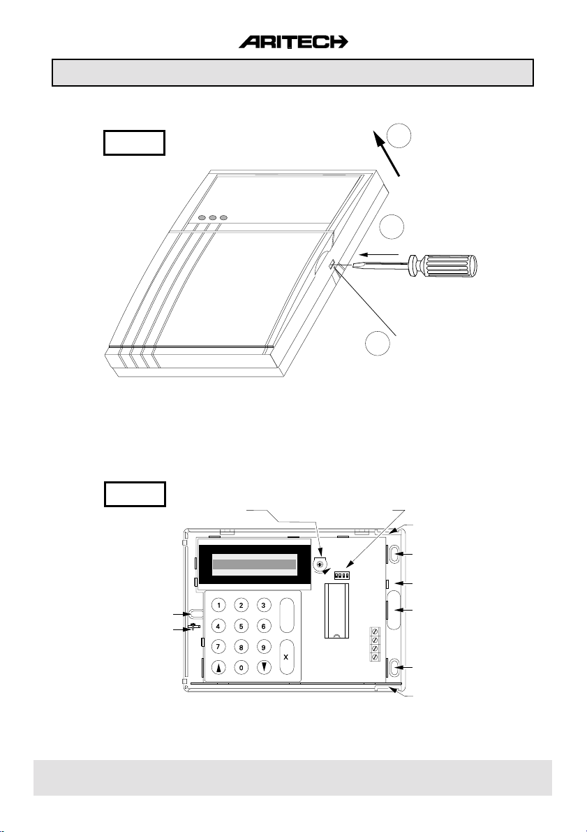
Keypad Installation
CD3008
CD3008
ADJUSTMENT
DISPLAY-CONTRAST
Figure 1.
PUSH
1
DIPSWITCHES
FOR KEYPAD ID
3
LIFT
2
PUSH IN CLIP WITH
SCREW DRIVER AND
LIFT UP LID
REMOVE SCREW
IF FITTED
CABLE ENTRY
FROM TOP
MOUNTING HOLE
SPARE SCREW
TO FIX COVER
ONTO BASE
✓
Figure 2.
MIN MAX
ON SD
1234
D
C
B
A
MOUNTING HOLE
PUSH CLAMP
GENTLY TO
REMOVE PCB
CABLE ENTRY
FROM BACK
MOUNTING HOLE
CABLE ENTRY
FROM BOTTOM
14 1791 9994
Page 5
Keypad Installation
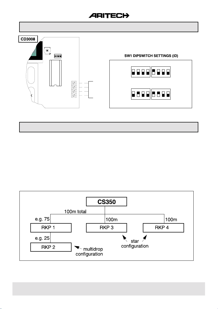
SW1
ON SD
MIN MAX
1234
ON
✓
CD3008
Control panel
Terminal 5
D
C
B
A
1234
OFF
Keypad 1
15
14
13
12
(all off)
ON
12341234
OFF
Keypad 3 Keypad 4
1234
Keypad 2
Figure 3.
Figure 4.
Wiring Specifications
Connect the additional keypads either using a STAR or MULTIDROP configuration.
MULTIDROP the keypads are 'daisy chained' together, each keypad being connected in parallel
STAR each keypad is wired back separately to the control panel terminals.
Any combination of the above wiring methods is allowed with the restriction that the total cable length
on each of the wiring loops (either multidrop or star) is restricted to 100m.
The following diagram shows how 4 RKPs may be connected using both methods.
to the one before it.
Figure 5.
14 1791 999 5
Page 6

Powering Up Panel
Connection of the control panel and the remote keypad in the following sequence allows the engineer
to establish that the control panel is working correctly.
Connection sequence:
1. Before installing the remote keypad (RKP) at it's designated position, it may be connected at
the control panel, to enable the engineer to commission the system.
2. Check that the ID for the RKP is set correctly... one keypad has to have ID1 (refer to Diagram
2).
3. Connect the RKP to the panel as shown in Diagram 3.
4. Replace the cover of the RKP and ensure that the tamper switch in the panel is closed.
5. Apply mains power to the panel. The system will power up in armed state (Factory Programme
Setting). If any zones are open at power up, the audibles will activate. The panel
defaults to the language select prompt when switched on for the first time [ UK/IRL Press é
1]. Enter [é] and [1] to select English language. Note that this also happens after returning to
factory default. See page 21 for more details.
6. Enter the Default User Security Code [1][1][2][2] at the keypad to disarm the system. The keypad
display shows DISARMING and the audibles, if sounding, will stop. Display then shows
any zones which are open and caused it to alarm. If [0] key is pressed at this stage, the display
will show FINISHED? . Enter ACCEPT [ü] to finish with operator menu.
7. The display shows Time/Date and the system is now disarmed.
8. Enter [1][2][7][8] (Default Engineer Code) to enter Engineer Mode and to change programme
parameters. See the Programming Map and Programming Functions for operational details.
How to programme is detailed on page 7.
9. Each time the system is powered down the panel memorizes it's current state, i.e. whether
armed, disarmed, partguard, etc. and will restore to that state when powered-up again.
14 1791 9996
Page 7

HOW TO PROGRAMME
All programmed features can be changed. The structure and position of the programming options
are illustrated in the Programming Map on the next page. Features and options are grouped together
and allocated to 6 main menu blocks:
1 MAINTENANCE 4 ZONES
2 TIMERS 5 OUTPUTS/REMOTES
3 USERS 6 MISCELLANEOUS
Once in Engineer Mode, the blocks can be accessed by 'stepping' through the menu blocks and
accepting the option shown in the display. The keys used for programme selections are defined as
follows:
[ê] stepping forward to next block or programming option
[é] returning to previous block or programming option
[ü] enter programming block - enter programming option - confirm changes - accept option
[X] quit programming block - quit programming option - reject changes
PROGRAMMING EXAMPLE
Adding Additional Keypads
After have installed the additional keypads - mind the correct dipswitch ID setting - go to the Engineer
Programming Mode and proceed as follows:
1. Use the [ê] key till OUTPUTS/REMOTES is displayed then enter [ü] .
2. Use the [ê] key till INSTALL REMOTE is displayed then enter [ü] .
3. The display shows the keypads connected, eg. REMOTE k k ✱ ✱ . Confirm [ü] these changes
when they are correct. If not correct, verify the wiring to the keypad and dipswitch ID settings.
The keypad must be powerless when changing dipswitch settings.
4. The display now shows INSTALL REMOTE . Quit programming blocks [X] till GOODBYE is
displayed. Now accept [ü] to leave the Engineer Programming Mode.
14 1791 999 7
Page 8

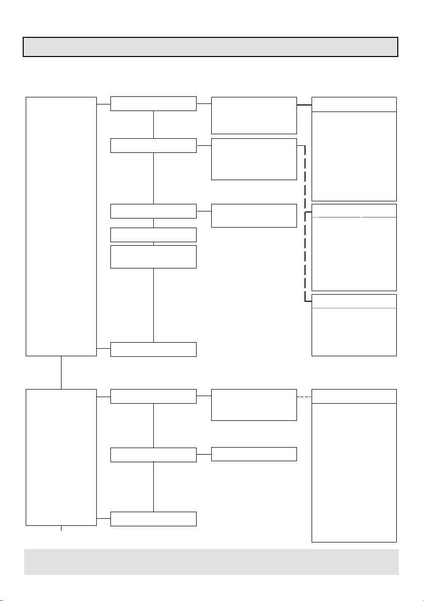
CS350 PROGRAMMIMG MAP V1.0
1 1 Engineer Log Display Log
Clear Log
Maintenance Menu
2 Output Test nn Low
nn High
MAINTENANCE 3 Show Open Zones All Closed
nn Zone
4 Walk Test Walk Test nn
5 LED Test Testing LEDs
Main Menu
2 1 Entry Time nn
2 Exit Time nn
3 Split Time OFF/ON
4 Bell Times Bell Cutout nn
Bel Delay nn
All Bells Cut ON/OFF
TIMERS Dig Cutout ON/OFF
Perim.Bell Cutout nn
Timers Menu
5 Time hh:mm Time hh:mm
6 Date dd/mm/yy Date dd/mm/yy
7 Summertime Forward Date
Backward Date
Summertime ON/OFF
Main Menu Timers Menu
or
or
3 1 Change Codes xx Code In Use
2 Code Privilege 01 Fs Us . . . . . . OK USER ATTRIBUTES
USERS Leave this Ps=Part Set
3 Engineer Code New Code Fs=Full Set
4 Duress Code New Code
5 Code Count nn
6
êê
Open Zones ON/OFF
Main Menu
xx Code Unused
New Code
Verify
Error
02 . . . . . . . . . . . OK
03 . . . . . . . . . . . OK Mn=Manager
04 . . . . . . . . . . . OK In=Inhibit
Us=Unset
Verify
Error
Verify
Error
14 1791 9998
Page 9
CS350 Programming Map
4 1 Zone Type 01 Alarm ZONE TYPES
2 Zone Attributes 01 In Key
ZONES 3 Shock Zones nn Gross. x Pls y ZONE ATTRIBUTES
4 Zone Name La=Local Alarm Contact
5 Loop Type : Alarm 24=24 hours
Loop Type : Dual Pg=Partguard
Main Menu Qs=Quick Set
0x . . . . . . . . . . . .
06 . . . . . . . . . . . . Unused
Leave this Tamper
PA
0x . . . . . . . . . . . . Fire
06 . . . . . . . . . . . . Exit/Entry
Leave this Alarm
Keypad Lock
Key Inf=Infinite Entry
Exit Trm=Exit Terminator
nn Wrong Type
Ls=Local Alarm Shock
In=Inhibit
So=Soak Test
Ac=Access
Ch=Chime
KEY ZONE ATTRIBUTES
Fs=Full Set
Ps=Part Set
Us=Unset
Pu=Pulsed
5 1 Output Type 01 Disarm/Arm OUTPUT TYPES
OUTPUTS / 2 Install Remote Remote kk** Latch
REMOTES Fire Detect Reset
Main Menu Perim.Alarm
0x . . . . . . . . . . . .
06 . . . . . . . . . . . . Disarm/Arm
Alarm
P.A.
Fire
Tamper
k=CD3008 Buzzer
Int.Bell
Ext.Bell
Partguard
System Clear
Trouble
Unused
Clear
14 1791 999 9
Page 10

CS350 Programming Map
6 1 Arm/Disarm Menu User Walk ON/OFF No Forced Arming
Forced Arm Opts Keep Inhibits
Rearm Options Clear when closed
ArmedDisplay ON/OFF Clear after exit
Exit Fault Buzzer/Bell
Final Door ON/OFF
Miscellaneous Menu Always rearm
2 P.A. Menu P.A. Silent/Bells
PA, LF Silent/Bells
éê PA ON/OFF
Miscellaneous Menu
3 Partgd/Chime Timed Partgd ON/OFF
Access>EE/Access
Partgd Digi ON/OFF
Latched Chime ON/OFF
Int.Bell Chime ON/OFF
Miscellaneous Menu
4 Eng. Reset Menu Reset Code/FTC or Code Only
P.A. Reset ON/OFF
Tamper Reset ON/OFF
MISCELLANEOUS Alarm Reset ON/OFF
Clear Engineer Reset
Miscellaneous Menu
5 Warnings PF Buzzer ON/OFF
LF Buzzer ON/OFF
Miscellaneous Menu
Never rearm
Rearm 1 to 8 Times
GOODBYE
6 Factory Prog Menu Engineer Lock ON/OFF
Miscellaneous Menu
7 Change Language English
Nederlands
Francais
Italiano
8 SysClear Inputs System Clear Mains ON/OFF
System Clear Battery ON/OFF
System Clear Fuse ON/OFF
System Clear Accs+EE ON/OFF
Main Menu Miscellaneous Menu
14 1791 99910
Page 11

1. MAINTENANCE MENU
CS350 Programming Functions
1.1 Engineer Log
1.1.1 Display Log
Use this function to consult the 40 event log
1.1.2 Clear Log
Will clear all events in the Engineer Log
1.2 Output Test
Use the [é ] and [ê ] keys to select the desired output. Use the [ü]
key to toggle the output polarity. Will return to its programmed status
when you move to the next output.
1.3 Show Open Zones
Will show any zone which is open. This is a useful test function.
1.4 Walk Test
Used to test individual inputs. Triggering the input will activate the
interior bell for 4 seconds,as well as latch and walk test outputs.
1.5 Led Test
This option will perform a sequential test of all keypad LED's
2. TIMERS
2.1 Entry Time
Programmable between 0 to 99 seconds.
2.2 Exit Time
Programmable between 0 to 99 seconds.
Engineer Log
Output Test
Show open zones
Walk Test
Led Test
Entry Time
Exit Time
2.3 Split Entry Time
When this option is set and the entry time is exceeded, then only the
interior bells will sound. Only after the additional entry time expired,
which is half the time programmed in 2.1, will a full alarm be created.
2.4 Bell Times
2.4.1 Bell Cutout
Programmable between 0-99 minutes for exterior bell. When a
time limit is required for interior bell then see 2.4.3.
2.4.2 Bell Delay
Programmed delay in minutes for interior and exterior bells which
becomes operational only when the system is set and no digi
fault condition prevails (negative to terminal 20).
2.4.3 All Bells Cut
Select for ON if interior bell must be timed for duration of 'Bell Cutout'
time
14 1791 999 11
Split Entry Time
Bell Times
Page 12

CS350 Programming Functions
2.4.4 Digi Cutout
Select for ON if the output type 'Alarm' must reset with the Bell
cutout time. If set to OFF then this output resets when the system
is disarmed.
2.4.5 Perimeter Bell Cutout
Programmed alarm time in minutes for the 'Perim.Alarm' output
type. The exterior bell and Perimeter bell output types will reset
after this time alarm expired. See also Peridiax feature on page
19.
2.5 Time
Programme time in Hours and Minutes: hh:mm
2.6 Date
Programme date: dd / mm / yy
2.7 Summertime
2.7.1 Forward date
Date at which clock is advanced with 1 hour (start of summertime).
2.7.2 Backward date
Date at which clock is returned with 1 hour (start of wintertime).
2.7.3 Summertime ON/OFF
Select for ON if automatic correction to summertime is required.
3. Users
3.1 Change Codes
Programme here user code 01 to 04. Use from 4 up to 6 digits with
the exception of '0'. Deleting a code is achieved by entering [ü]
after appearance of [New code _ ]. Code 4 can be used with a
code counter (see 3.5). Factory default code for user code01is
[1122].
Bell Times
Time
Date
Change Codes
Code Privileges
3.2 Code Privileges
Allocate operational functions to each code.
Attribute Function
. Mn change codes, time, date, read engineeer memory,
access to chime function
. In inhibit zones
. Ps part set of system
. Us unset of system
. Fs full set of system
3.3 Engineer Code
Programme here new Engineer code. Factory default is [1278].
Engineer Code
14 1791 99912
Page 13

CS350 Programming Functions
3.4 Duress Code
Programme here the code which will disarm the panel and activate
the Personal Attack output. The output restores after entering a
user code.
3.5 Code Count
Programme the amount of times code 4 can be introduced. When set
to '99' code 4 is always operational. Setting to '0' disables the code.
3.6 êêOpen Zones On/Off
When this option is programmed to 'On' then a keyswitch user will
be able to view any open zones by pushing twice the [ê ] button.
3.7 Quick codes On/Off
When this option is programmed to 'On' it is possible to fast arm the
panel.
The following three keystroke sequences are possible :
[0] [ê] [4] Arms system with exit time.
[0] [ê] [5] Arms system immediately (no exit time).
[0] [ê] [7] Arms system partially (Part Set).
4. ZONES
4.1 Zone Type
Define here the typical function of each input.
TYPE FUNCTION
. Unused Input is not operational
. Tamper Input is 24Hrs operational. Activation of input causes
'internal bell' alarm in disarmed state and full alarm in
armed state. The input is automatically bypassed after
an alarm till the second valid entry of a user code.
output : tamper, alarm, int.bell, ext.bell, system clear, fire
reset
. P.A. Input is 24Hrs operational. Silent or audible Personal
Attack alarm is determined in function 6.2.1.
output : P.A., system clear, fire reset
. Key Input is 24Hrs operational to arm/disarm system. The
exact operation will be determined by the attributes allocated in function 4.2. Use Pulse keyswitches if more
than one input is to be used as Key zone.
output : disarm/arm, buzzer, latch
. Fire Input is 24Hrs operational. Activation of zone will cause
the sirens to pulse on and of. The input is automatically
bypassed after an alarm till the second entry of a valid
user code.
output : fire, interior bell, exterior bell, system clear, fire
reset
Duress Code
Code Count
Open Zones
Quick Codes Off
Zone Type
14 1791 999 13
Page 14

CS350 Programming Functions
TYPE FUNCTION
. Exit/Entry Input is bypassed during exit time when arming the
system. If after the exit time the zone is still open, the
panel will not arm and act as programmed in
function 6.1.5. During the entry procedure the entry
timeris started which allows disarming.
output : buzzer, alarm, interior bell, exterior bell, fire
reset
. Alarm Input is only active when the system is armed and
it will act according to its programmed attributes.
outputs : alarm, interior bell, exterior bell, system
clear, fire reset
. Keypad Lockopening this input will disable access to the keypad.
. Key Infinite creates an infinite exit time. Only after opening and
closing this zone will the panel arm after four
seconds. Re-activation starts an infinite entry time.
. Exit The exit time stops and system arms 4 seconds
after Terminator closing the input.
4.2 Zone Attributes
Attributes define the operation of the zone type. Some types
have attributes inherent to them. Others can not be changed
which will be displayed by [No Option].
ATTRIBUTE FUNCTION
. In Allows inhibiting of alarm and exit/entry zones
. 24 Creates a 24Hrs zone. Only applicable for Alarm types.
. Pg Partguard. Zone is inhibited during partguard protection.
. So Soak Test. The related input will not activate any alarm output
but only log its events.
. Ac Access zone. Follows the exit/entry input. Will create a direct
alarm when triggered prior to the exit/entry input, except if programmed for Access/EE and the panel is in Partguard mode (see function
6.3.2.).
. Ch Chime. Input activates buzzer/ interior bell when in disarmed
state.
. Ls Local Shock. Shock sensor alarm triggers 'perimeter' output
instead of 'alarm' output. See also Peridiax programming on p.19.
. La Local Alarm. Both shock sensor and/or contact activation will
trigger the perimeter output. See also Peridiax programming on p.19.
Zone Type
Zone Attributes
Key Zones
14 1791 99914
Page 15

CS350 Programming Functions
KEY ZONE ATTRIBUTES
. Fs Full set. Keyswitch fully arms system.
. Ps Part set. Keyswitch partially arms system.
. Us Unset.Keyswitch disarms system.
. Pu Pulse.Keyswitch used must be a pulse type. Allows
arming/disarming with multiple keyswitches in a system.
. Qs Quick set. Keyswitch arms panel without exit time.
4.3 Shock Zones
Input 1 to 4 can be programmed to analyse enertia shocks (e.g. GS610).
Two types of attack can be calibrated for. Heavy attacks ( 'gross'
level) and small repetitive attacks ('pulse' count). The pulse count
ismonitored after the first triggering in a window of 30s with 1s
intervals.
4.4 Zone Names
Programme here personalised names for each input.
(See page. 20 for example.)
4.5 Loop Type
Inputs can be configured to detect alarm contact activations only
('Alarm') or alarm and tamper violations within the same loop ('Dual').
5. OUTPUTS / REMOTES
5.1 Output Type
Define here the typical function of each output (1 to 6).
TYPE FUNCTION
. Disarm/Arm Reflects the control panel's arm/disarm status.
. Alarm Switches with intrusion and tamper alarm
(Tamper only when armed).
. PA Switches with PA alarm and / or Duress alarm.
. Fire Switches with a fire alarm.
. Tamper Switches with a 24Hrs and / or a tamper alarm.
. Latch Switches after exit time and / or walk test. Resets
with disarm or start of entry time.
Used withlatching sensors.
. Fire Reset Switches with second entry of a valid user code
after an alarm or after leaving the user log.
. Buzzer Follows the buzzer operation of the keypad.
. Interior Bell Follows the interior bell status.
. Exterior Bell Follows the exterior bell alarm time.
. Partguard Switches when control panel is part set.
. System Clear Reflects the system status according to the
optionsprogrammed in function 6.8.
. Trouble Indicates a system error : E²PROM error, line fault,
RKP fault, low battery, mains failure. The RKP will
display the cause of trouble.
Zone Attributes
Shock Zones
Zone Names
Loop Type : Alarm
Output Type
14 1791 999 15
Page 16

CS350 Programming Functions
TYPE FUNCTION
. A Alarm Switches with a perimeter alarm for the duration as
programmed in function 2.4.5. In this case the
exterior bell follows the A Alarm.
. Unused Output is not used.
5.2 Install Remotes
Only one keypad is installed when the panel is powered-up from
factory default. Additional keypads must be initialised by the panel
before they become active. When selecting [ü] install remotes, the
display will show the keypads which it recognizes, for example two
keypads: [Remote kk**]. Now enter [ü] again to initialize the other
keypad(s).
6. MISCELLANEOUS
6.1 Arm / Disarm Menu
Programming of options associated with arming / disarming.
6.1.1 User Walk On/Off
When an input is open during arming of the panel, the interior
bell will give a short activation each time a zone is closed.
6.1.2 Forced Arm Opts
Determine here the' forced arming' conditions. Input(s) and
code(s) must have the 'In' attribute to be able to force arming of
the panel. Forced arming can be achieved in three ways.
a) Go to the [Forced Arm ] menu in the user mode and accept.
b) Arm the panel and enter [éé] when the display shows [Open
Zone(s)].
c) Arm the panel with a keyswitch while a 'forced arm' option
has been programmed.
Option Operation
. No forced arming Forced arming is not possible.
. Keep inhibits Open zones are omitted till the panel is dis-
armed.
. Clear when closed Open zones are omitted till they close
again. From that moment on they can detect
again.
. Clear after exit Open zones are omitted till the exit time has
expired, after which they can detect again.
Output Type
Install Remotes
Arm/Disarm Menu
6.1.3 Rearm Options
Define the condition of retriggering of bells.
Option Operation
. Always Rearm The same input when activated, will al-
ways retrigger sirens.
. Never Rearm The same input will not re-trigger the sirens.
. Rearm 1 to 8 times Limits the number of re-triggerings as
programmed.
14 1791 99916
Page 17

CS350 Programming Functions
6.1.4 Armed Display On / Off
Determines if the display will show the armed status or time & date
when armed.
6.1.5 Exit Fault Buzzer/Bell
Deterines if the buzzer only or buzzer + interior bell will activate
with an exit fault.
6.1.6 Final Door On / Off
After introducing the code, the panel will arm 4s. after having opened
and closed the exit zone or access zone even before the exit time
has expired.
6.2 P.A. Menu
6.2.1 P.A. Silent/Bells
Programme if a PA alarm must be silent or loud.
6.2.2 PA,LF Silent/Bells
Programme if a PA alarm must be silent or loud when a phone line
fault is present.
6.2.3 éê PA On/Off
Programme if the keypad panic buttons are operational or not.
6.3 Partguard / Chime
6.3.1 Timed Partguard On/Off
Define if the panel is armed with or without exit time.
6.3.2 Access zones with Partguard
Define if an access zone becomes an entry/ exit zone when
partially armed or not.
Armd/Disarm Menu
P.A. Menu
Partguard/Chime
6.3.3 Partguard Digi On/Off
Define if the alarm output operates when partially armed or not.
6.3.4 Latched Chime On/Off
If Latched Chime is set to On, the chime will remain operational
each time the system is disarmed untill manually canceled by user.
6.3.5 Interior Bell Chime On/Off
Define if the interior bell follows the chime function or not.
6.4 Engineer reset menu
Define the conditions which will call for an engineer reset. When
a panel asks for [Call Engineer nn], were nn is a number, the user
can't arm his panel.
6.4.1 Reset Code/FTC input or Code only
When made negative,Input 20 (Fail To Communicate or Digi Fault)
may be used to clear engineer reset. When only a code is allowed
to reset, programme for [Reset Code Only].
14 1791 999 17
Engineer reset
Page 18

CS350 Programming Functions
6.4.2 P.A. Reset On/Off
Define if PA alarm requires engineer reset or not.
6.4.3 Tamper Reset On/Off
Define if Tamper alarm requires engineer reset or not.
6.4.4 Alarm Reset On/Off
Define if Alarm type input (including Tamper when armed)
requires engineer reset or not.
6.4.5 Clear Engineer Reset
Clear an engineer reset request. [Reset Cleared !] will be
displayed.
6.5 Warnings
6.5.1 PF Buzzer On/Off
Define if a 230V mains failure must trigger the buzzer output.
6.5.2 LF Buzzer On/Off
Define if a Digi Fault (via input 20) must trigger the buzzer output.
6.6 Engineer Lock
Define if an engineer code is required to factory default the
panel. See also the chapter returning to factory default.
6.7 Change Language
Change the language used by the panel to Dutch, French or Italian.
6.8 System Clear Inputs
Define the parameters which will determine the function of the
System Clear output.
P.A. Menu
Warnings
Engnr. Lock Off
Change Language
System Clear
Inputs
6.8.1 System Clear Mains On/Off
Will a 230V mains failure switch the output off or not.
6.8.2 System Clear Battery On/Off
Will a battery failure switch the output off or not.
6.8.3 System Clear Fuse On/Off
Will a fuse failure switch the output off or not.
6.8.4 System Clear Access + EE On/Off
Will an open access or EE zone switch the output off or not.
14 1791 99918
Page 19

Peridiax Feature
The CS3503 control panel has been equipped with Aritech's new Perimeter and Dialler eXtended
programming option.
How It Works
When the panel is armed and not in alarm state, activating a perimeter zone will cause a PerimeterAlarm or Local Alarm. This means that both internal and external bells sound for a programmable
number of minutes (perimeter bell time).
l A Perimeter Alarm digi output will turn on and reset at the end of the perimeter bell cutout time.
l The main alarm digi will not turn on.
l Engineer reset and rearm option are not activated by Perimeter-Alarm.
l Perimeter-Alarms that occur during exit time, after silent PA etc. are treated like normal alarms.
l Perimeter-Alarms that occur during bell delay/cutout will merely set Perimeter-Alarm digi output.
l The output functionality is fixed... both bells go for the Perimeter-Time when a Perimeter-Alarm
happens.
Typical Application Example
WIRING
Figure 6.
PROGRAMMING AND OPERATION
PROGRAMMING
Zone Attribute
NO La
NO La
La
La
For programming see Programming
Shock Option
Ls
No Ls
Ls
No Ls
Inertia Activation
'Perimeter' Alarm
'Full' Alarm
'Perimeter' Alarm
'Perimeter' Alarm
Zones è Zone attributes Ls for Shock (Zone 1-4)
Map:
è Bell times è perim. bell cutout ON/OFF
Timers
WEAPON AGAINST FALSE ALARMS
Consider, for example, the situation where the inertia sensor and magnetic contact are wired in series
and mounted on a window. When only the zone attributes Ls is added , then the panel will cause
a local alarm for inertia sensor activations and a full alarm when the window opens.
14 1791 999 19
OPERATION
Contact Activation
'Full' Alarm
'Full' Alarm
'Perimeter' Alarm
'Perimeter' Alarm
La for Contacts(Zone 1-6)
Page 20

Programming Text
Literal text is available for programming customized zone and user names. The keypad digits each
represent a set of characters.
KEYPAD CHARACTER SET
ABC DEF GHI
JKL
STU
MNO
VWX YZ
PQR
✓
The [9] key has a blank space and
CURSOR
LEFT
HOME
CURSOR
RIGHT
punctuations (eg. full stop, comma,
etc.).
The [0] key has a blank space.
SCROLL
UP
SCROLL
DOWN
HOW TO PROGRAM NAMES
Function keys used:
ê key Move to next character.
é key Move to previous character.
4 key . Confirm to reprogram current text
. Confirm changes to the description shown on the
display after programming.
key . Restart the programming of a name
X
. Return to previous menu section.
EXAMPLE
Reprogram zone 1 01 zone to 01 Door .
l Enter engineer mode [0][1][2][7][8]
l Jump to zones - zone name [4][4] - display shows 01 zone
l Confirm to reprogram 4 - display shows 01 _
l Start programming capital letter'D' [2] - display shows 01 2
Repeat steps till 'D' appears [2]+[2]+.. - display shows 01 D
l Move to next character ê - display shows 01 D_
l Repeat programming sequence for all characters.
l Confirm new name when the last character shows on the display 4 you can now proceed with
the next name ê or return to the previous menu section X .
14 1791 99920
Page 21

Returning to Factory Default
Without Engineer Lock programmed
1. Remove all power from the panel. Mains and the battery.
2. Remove the plug-on link (JP1) on the panel.
3. Restore the mains power.
4. The Display will prompt for the Language Default prefered. The display will change every two
seconds.
UK/IRL Press é1
NL Toets é2
F Taper é3
I Ins. é4
4. Enter at Keypad 1 the default operators code [0][1][1][2][2].
5. Enter at Keypad 1 the default engineer's code [0][1][2][7][8].
6. Replace the plug-on link and reconnect the battery.
With Engineer Lock programmed
1. Enter Engineer Mode using EXISTING Engineer code at Keypad 1.
2. Select 'Factory Prorgram Menu' from the miscellaneous section and scroll down to 'Default
Settings'. Enter accept ✔ .
NOTE: . When the existing engineer code is unknown, then the control panel must be
returned to the factory for reprogramming.
. The panel always powers up in Armed condition.
Quick Codes
The use of operator "Quick Codes" can be enabled or disabled by setting "Quick Code" to ON or
OFF in the Use Menu.
The quick codes are as follows:
0¯4 Normal Set.
0¯5 Alarm Set (No Buzzer).
0¯7 Alarm Partguard Set.
14 1791 999 21
Page 22

Zone Wiring Options
General
The main control panel inputs are set up as standard EOL (4K7) zones which are freely
programmable to whichever type is required. However, by selecting option 'dual' from the
'zones' menu all main control panel zone inputs can be programmed to give ALARM and
TROUBLE indication ON THE SAME ZONE (Fig. 7.).
Wiring
1. The ALARM devices are wired as normal and a 4K7 resistor is fitted in PARALLEL with
the complete loop.
2. The TAMPER switches/devices are wired as normal and a 4K7 resistor is fitted in series
with this loop.
Principles of Dual Operation
All devices closed ....... loop resistance is 4K7
TAMPER device open loop is open circuit
ALARM device open ... loop resistance is 9K4 (ie EOL resistor PLUS parallel resistor)
Example 1
Four wire application for powered motion sensors
Example 2
Multiple sensors wired in a single zone
Figure 7.
Figure 8.
14 1791 99922
Page 23
AS290 / AS390
BEACON CONTACTS
SPEAKER
TAMPER
SWITCH
-
(black)
BATTERY
(red)
+
+
-
-+ -+
1 2 3 4 5 6 7 8 9 10
Wiring of Aritech Sirens
16
TAMPER LOOP
-
INPUT POWER (13.0-14.2)
+
SIREN HOLD-OFF VOLTAGE (*)
BEACON HOLD-OFF VOLTAGE (*)
*) Program Internal (5) and External (7)
Bell outputs for positive (+) trigger
4K7
17
3
2
5
7
CUT-OFF
TIMER
Figure 9.
J2 J1
JUMPERS CUT-OFF TIMER: (minutes)
J1
J2
✲= cut link
✲
✲
✲
✲
10’:
20’:
3’:
5’:
14 1791 999 23
Page 24

Wiring of Outputs
Principle of operation from outputs.
Output as shown is 'High'. When programmed for '-'
trigger
the output will switch to '-' with an alarm condition.
Figure 10.
Wiring to Digital Communicator
Figure 11.
Figure 12.
Wiring of Fire Detectors
14 1791 99924
Page 25

List with Short Codes
A
Armed display on ................................ 61 4
B
Bell cut-out time, program ................... 24 1 mm
Bell delay, program ............................ 24 2 mm
Bell option, exit fault ........................... 61 5
Bells cut option, all ............................. 24 3
Buzzer option, line fault ...................... 65 2
Buzzer option, power failure ............... 65 1
C
Change of hour backward .................. 27 2
Change of hour forward ...................... 27 1
Chime option, latched ........................ 63 4
Chime, internal bell on........................ 63 5
D
Date, program curren ................. 26 DD MM YY
E
Engineer code, program ..................... 33
Engineer lock select ........................... 66 2
Engineer reset clear ........................... 64 5
Engineer reset PA .............................. 64 2
Engineer reset tamper ....................... 64 3
Engineer reset (Alarm) ....................... 64 4
Entry time, program ............................ 21 SS
Exit time, program .............................. 22 SS
F
Factory default program select .......... 66 N
Final door set ...................................... 61 6
Forced arm select ............................... 61 2
I
Input attibute, program ....................... 42 NN
Input name, program .......................... 44 NN
Input option, A/T dual ......................... 45
Input type, program ............................ 41 NN
Input values, program inertia.............. 43 NN
Input walk test .................................... 14 NN
Inputs, show open .............................. 13
Install new remotes ............................ 52
L
Log, clear ............................................ 112
Log, display the .................................. 111
O
Output type, program .......................... 51 NN
Output, test .......................................... 12 NN
P
PA at keypad, select ...........................62 3
PA option, lien fault silent .................... 62 2
PA option, silent .................................. 62 1
Partguard, access to exit on ............... 63 2
Partguard, digi options ........................ 63 3
Partguard, timed/instant ......................63 1
R
Rearm options select ..........................61 3
S
Split entry time, program .....................23 SS
Shock perimeter select........................ 46
T
Time, program current......................... 25 HH
MM
U
User attributes, change .......................32 N
User code, program.............................31 N
User walk test, select .......................... 61 1
Key to Abbreviations:
HH Enter number of hours
mm Enter number of minutes
N Enter number of User Code
NN Enter number of output/zone
SS Enter number of seconds
DD Enter number of days
YY Enter year
MM Enter month
HOW TO WORK WITH SHORT CODES
Instead of using the - ¯ ✔ keys to access
programming options, it is possible to directly
jump to the menu section required. Immediately after you enter the engineer code, keyin one of the digit sequences as indicated in
the Short Code List.
14 1791 999 25
Page 26

Default Chart
No. Default Required
ZONE TYPES
1 Exit/Entry
2 Alarm
3 Alarm
4 Alarm
5 Alarm
6 Alarm
OUTPUT TYPES
No. Default Required
1 Arm/Disarm
2 Partguard
3 Latch
4 Tamper
5 Int. Bell
6 Ext. Bell
TIMERS
Description Default Required
Exit time 30 sec.
Entry time 30 sec.
Split ent. time off
Bell delay 0 min.
Bell cut off 30 min.
OTHER OPTIONS
Function Default Required
Buzzer for line ON
fault
Buzzer for pow- ON
er failure
Latched chime OFF
Chime rings Int. OFF
bell
Current date 01Jan92
Current time 00 00
Engineer lock
Engineer reset Code+FTC
option
Engineer reset OFF
Select
Type In Pg Ch 24 Ac
ZONE ATTRIBUTES
So
Alarm l
Tamper x x x x x x
PA x x x x x x
Fire x x x x x x
E/E l x l x x x
CODES & PRIVILEGES
No. Default Fa Ps Us In Mn Cn
1 1 1 2 2 llll x
2 Unused x
3 Unused x
4 Unused l
Duress Unused xx xxx x
Ud code Unused xxxxx x
Eng. 1 2 7 8 xxxxx x
Pu Qs Fs Ps Us
Key ll
OTHER OPTIONS cont'd
Function Default Required
Exit fault of buz- BUZZER
zer/bell
Final door set OFF
Forced arming OFF
Inputs alarm or ALARM
dual
Keyswitch PULSED
option KEY
PA at keypad OFF
PA with line fault BELLS
bells or silent
PA activations BELLS
bells or silent
Partguard OFF
acces to E/EE
Partguard OFF
activates digi
Partguard INSTANT
time/instant
Auto rearm NEVER
option
x = Not Available (for attributes and privileges charts) l = Default
14 1791 99926
Page 27

Problem Solving
Bells do not ring at 1. Check bell fuse.
bell test. 2. Disconnect bell cable from control panel and connect across battery
Alarm zone does not Arm system and remove wires from the terminal block. If the system does
activate system. not activate, disarm and enter Engineer Mode.
Alarm zone name will 1. Enter Engineer mode and open panel.
not clear from the 2. Disconnect the alarm zone wires from the terminal block and replace with
display when attempt- a 4K7 resistor.
ing to arm the system. 3. Enter 'Show Open Zones' in 'Maintenance Menu' and observe that the
Control panel activates 1. Check that the battery is connected correctly.
during a short power 2. Check that the battery fuse is not blown.
failure. 3. Ensure that the battery is fully charged and is large enough to carry the
load of the system.
observing correct polarity. If wiring is correct the bell should ring.
1. Check if bell delay time is programmed for [00] ('Timers Menu' at 'Bell
Times').
2. Check if zone is not in soak test ('Zones Menu' at 'Zone Attributes').
3. If PA zone, check that it is programmed as audible ('Miscellaneous Menu'
at 'PA Menu').
zone name in question does not come up on the display. This proves
that the panel is functioning correctly.
4. Check the zone wiring to ensure that the circuit is closed and that there
are no shorts on the cables. Reconnect the wires back to the panel and
retest.
System returns to Check that jumper is on link LK1 on the main control panel.
factory setting when
mains and battery
powre are removed.
System activates Before leaving engineer mode check that no PA, FIre, Medical, or Tamper
when leaving engineer zones are open. Use 'Show Open Zones' menu to do this.
mode.
System does not
activate when Tamper
opens during day
(ie when system is
disarmed).
14 1791 999 27
Check that the internal sounder is connected.
NOTE: the external bell only sounds on tamper fault when the system is
armed. If using dual loops, check that the zone type is programmed for
DUAL (in 'Zones' menu) and that the Tamper devices are wired in series with
the EOL resistor.
Page 28

Problem Solving
Alarm zones cannot
be inhibited.
Bell fuse blows when
bells are sounding.
PA is activating when
alarm is switched off.
'No panel data' shows
on the display.
Check that the 'In' attribute is set for this zone number
('Zone Attribute' in 'Zones' menu). Check that the user code has 'In' privilege
('Code Privileges' in 'Users' menu).
Check that there is no short circuit in bell wiring.
Disconnect bell wires from terminal and, observing correct polarity, connect
across battery. If bells ring, wiring is correct. The load of the bells is greater
than the fuse rating, inserting a higher value fuse may damage the panel.
Spread the load of the bells across the bell outputs or fit a relay and use the
auxiliary power output to provide some of the current.
Ensure that the operator is not entering the duress code when switching off
the system.
This happens when the keypad is not receiving correct data from the panel.
Check wiring to the keypad, especially for swapped wires.
Check that the address is correctly set on the keypad.
14 1791 99928
Page 29

Technical Specification
Power Input 230 V AC ±10%, 50Hz, 14.5 VA
Current CS350 Quiescent: 30mA Alarm: 50mA
Consumption CD3008 Quiescent: 30mA Alarm: 50mA
Output Voltage 13.8 V DC ±5%
Signalling Output Internal bell 800mA 2A
External bell 800mA 2A
Programmable 50 mA each
Outputs
Loop 6 inputs, configurable as double-pole loops using 4K7 resistors.
characteristics Response time: 300 ms.
Battery 12 V lead acid rechargeable battery (not supplied)
Backup Float charging method at 13.8 V ±5%, 800mA max.
charging current. 6.5 Ah recommmended
Auxiliary Power 13.8 V DC fused at 800mA.
Output
Note: if the combined current is greater than 800mA for the above devices, the load will be shared
by the standby battery.
Normal Surge
14 1791 999 29
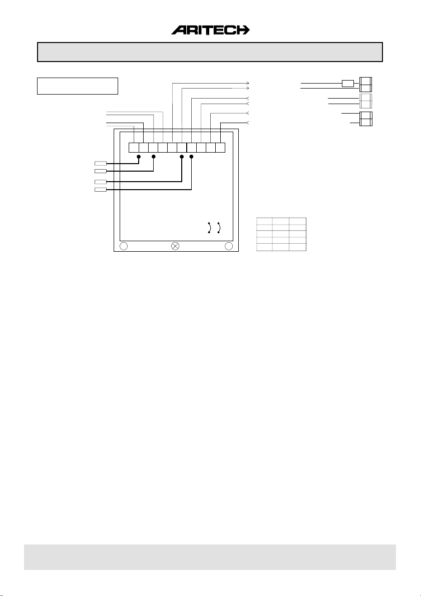
Page 30

FACTORY
SETTINGS
CS350 WIRING DIAGRAM
E.O.L.
N.C.
N.C.
N.C.
N.C.
N.C.
N.C.
A B C D
+
-
Figure 13.
- +
1 2 3 4
+ - + - + -
✆
14 1791 99930
Page 31

14 1791 999 31
Page 32

Aritech is an ISO 9001 certified manufacturer.
14 1791 99932Aritech reserves the right to change specifications without notice. .4
 Loading...