

Page 1

2000 SERIES SENSORS
Revision 3.1 : June 1997
INSTALLATION GUIDE
Downloaded from: http://www.guardianalarms.net
Page 2

Page 3

CONTENTSCONTENTS
1. INTRODUCTION 1
1.1 SCOPE 1
1.2 2000 SERIES PRODUCTS OVERVIEW 2
2. INSTALLATION 3
2.1 GENERAL 3
2.2 AUTOMATIC FIRE SENSORS 3
2.2.1 Where To Place Automatic Fire Sensors 3
2.2.2 Mounting Bases & Wiring Diagrams 4
2.2.3 Addressing 7
2.2.4 Technical Data 7
2.2.5 7-Segment Indication 8
2.2.6 Diagnostics and Sensitivity Test Modes 9
2.2.7 Testing, Maintenance and Cleaning 10
2.3 MANUAL CALL POINT (MCP) DM2000 DM2010 DM2020 12
2.4 ISOLATOR IU2016 14
2.5 FIRE MONITORING CONTROLLERS 16
2.5.1 Zone Monitoring Unit IU2051 16
2.5.2 Indicating Circuit Controller IU2080 19
2.6 INPUT / OUTPUT UNITS 27
3. LOOP LOAD CALCULATIONS 30
3.1 GENERAL 30
3.2 CALCULATION PROCEDURE 30
3.2.1 Standby Current 31
3.2.2 Alarm Current 31
3.2.3 Loop Resistance 32
Page 4

Page 5

1. INTRODUCTION
1.1 SCOPE
This document is a guide for the installation of the Aritech 2000 Series Range of Analogue
Addressable Fire Monitors and Aritech 2000 Series Monitoring Controllers and Input / Output
Units.
Other manuals are:
FP2000 Series Reference Guide LKFP2503
FP2000 Series Network Configuration Guide LKFP2303
FP2000 Series End User Instruction Manual LKFP2403
Product Code
Page 6

1.2 2000 SERIES PRODUCTS OVERVIEW
Product Part Number Base
Temperature Monitors:
Single LED without remote LED driver DT2053 DB2001(U)
Single LED, 7-segment display, remote LED driver DT2073 DB2002(U)
Two LED with remote output DT2063 DB2002(U)
Ionisation Smoke Monitors:
Single LED without remote LED driver DI2052 DB2001(U)
Single LED, 7-segment display, remote LED driver DI2072 DB2002(U)
Two LED with remote output DI2062 DB2002(U)
Optical Smoke Monitors:
Single LED without remote LED driver DP2051 DB2001(U)
Single LED, 7-segment display, remote LED driver DP2071 DB2002(U)
Two LED with remote output DP2061 DB2002(U)
Manual Call Points:
Manual Call Point DM2000 —
Manual Call Point : IP66 DM2010 —
Manual Call Point : yellow for gas release DM2020 —
Isolator:
Isolator IU2016 DB2003
Fire Monitoring Controllers:
Zone Monitoring Unit IU2051 —
Indicating Circuit Controller IU2080 —
Input / Output Units:
4 Inputs / 4 Outputs IO2034 —
2 Inputs / 2 Outputs IO2032 —
2 Inputs / 1 Output IO2031 —
4 Inputs IO2014 —
Optional Housing for I/O units
(123mm (W) x 173mm (L) x 50mm (H)) IOBOX —
Table 1 : Aritech 2000 Series Products
Page 7

2. INSTALLATION
2.1 GENERAL
The FP2000 Series Analogue Addressable Fire Panels can address up to 128 Aritech
devices on a two-wire ring circuit (loop) using digital communication.
The following paragraphs will describe the connection and addressing of Aritech devices
in a fire protection system.
2.2 AUTOMATIC FIRE SENSORS
2.2.1 Where To Place Automatic Fire Sensors
SITING AND SPACING DETECTORS
Please consult local regulations and follow Fire Brigade requirements.
The following apply for flat, horizontal ceilings:
SMOKE
DETECTORS
Max. area coverage 100m
Max. horizontal distance between any point in
the area and the nearest detector
Max. ceiling height (general limits) 12m 6m
Note that these values change if:
• appliance is in small corridors
• there are obstructions
• appliance is in the apex of a pitched roof
2
6m 5m
HEAT
DETECTORS
50m
2
Page 8

SUITABLE LOCATIONS FOR SMOKE & HEAT DETECTORS
General rule : ION : Flaming Fire
OPTICAL : Smouldering Fire
HEAT : Full Combustion Fire
LOCATION ION OP
T
Corridor / Walkway # Air current may exist
Elevator Shaft / Duct # Air current is present
General Office / Day Room #
Hotel Foyer #
Dining Room #
Theatre Stages / Audience
Hall
Warehouse # Not if diesel fork lifts
School #
Clinic / Nursery Room #
Laboratory #
Studio / Recording Room # Possibility of flaming
Factory #
Church / Chapel #
Cargo Handling Area # Presence of air current
Spirit Fuel Store # Fast, clean burning fire
Library Room #
Central Heating Room #
Dryer Room #
Kitchen # Avoid locations over
Smoky Atmosphere #
Closed Parking Area #(1) # (1) : delayed or double
#
HEAT REMARKS
are used
fire
& dust
ovens
knock
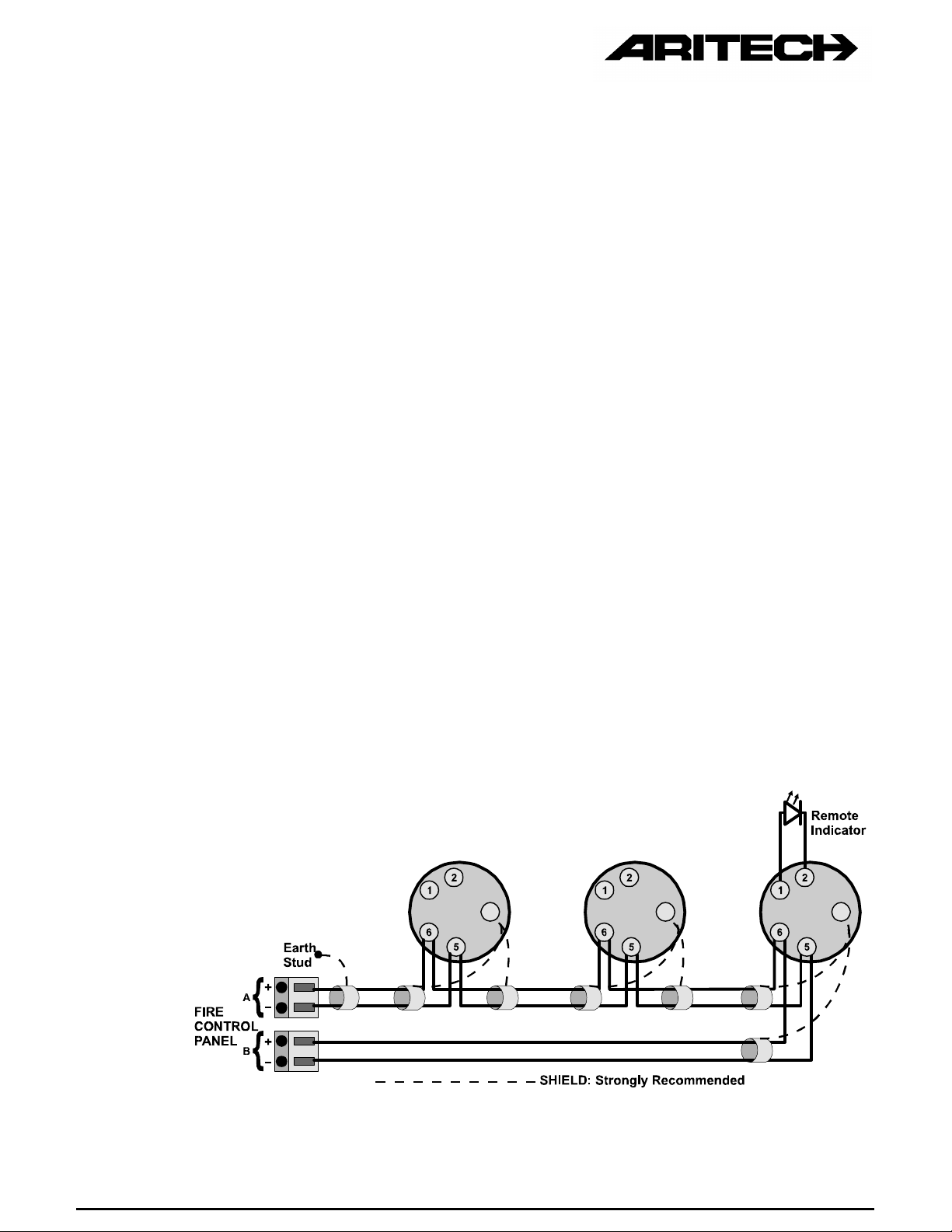
2.2.2 Mounting Bases & Wiring Diagrams
All connectors on the base are numbered and have the following function:
1 : (+) remote LED
2 : (-) remote LED
5 : (+) line in and out
6 : (-) line in and out
Earth : to continue ground shield
Page 9
There are 4 different Mounting Bases available for the 2000 Series Sensors:
DB2001 : sensor base without remote LED connectors (Ø 10 cm)
DB2001U : sensor base without remote LED connectors (Ø 15 cm)
DB2002 : sensor base with remote LED connectors (Ø 10 cm)
DB2002U : sensor base with remote LED connectors (Ø 15 cm)
When sensors with remote LED drivers are being installed (for example DT2073,
DI2072, DP2071), the DB2002 or DB2002U should be used.
Please refer to Figure 1 for Class A, and Figure 2 for Class B (no return) wiring.
It is not necessary to observe polarity on terminals 5 and 6 as the fire monitors are not
polarity sensitive, but when the remote LED driver is being used, polarity must be
observed !
To install a detector head, insert the head and rotate it clockwise until it is properly
aligned and "sets" into the base (Figure 3). Then rotate it an additional 15º to lock it in
place.
Each 2000 Series Universal Mounting Base is equipped with a moulded locking
mechanism to prevent unauthorised removal of the sensor head (Figure 4). If you want
detectors to be locked into the base, remove tab before inserting into the base. To
remove the sensor head, insert a small screwdriver into the slot on the side of the base
and press in while simultaneously turning the sensor head counter clockwise (Figure 5).
The different Aritech Mounting Bases are designed so that the fire sensors will not
operate in the Isolator Mounting Base DB2003 and vice versa. The 2000 Series Range
of Fire Sensors will also not fit the base of another Aritech Range of Sensors.
A ground shield is strongly recommended, but not required. The shield must be
connected to the earth ground at one point only, preferably via an earth stud in the fire
control panel.
Address tags are available to write the address of the detector on. The address tag
should be positioned before the base is mounted.
Figure 1 : Class A Wiring
Page 10
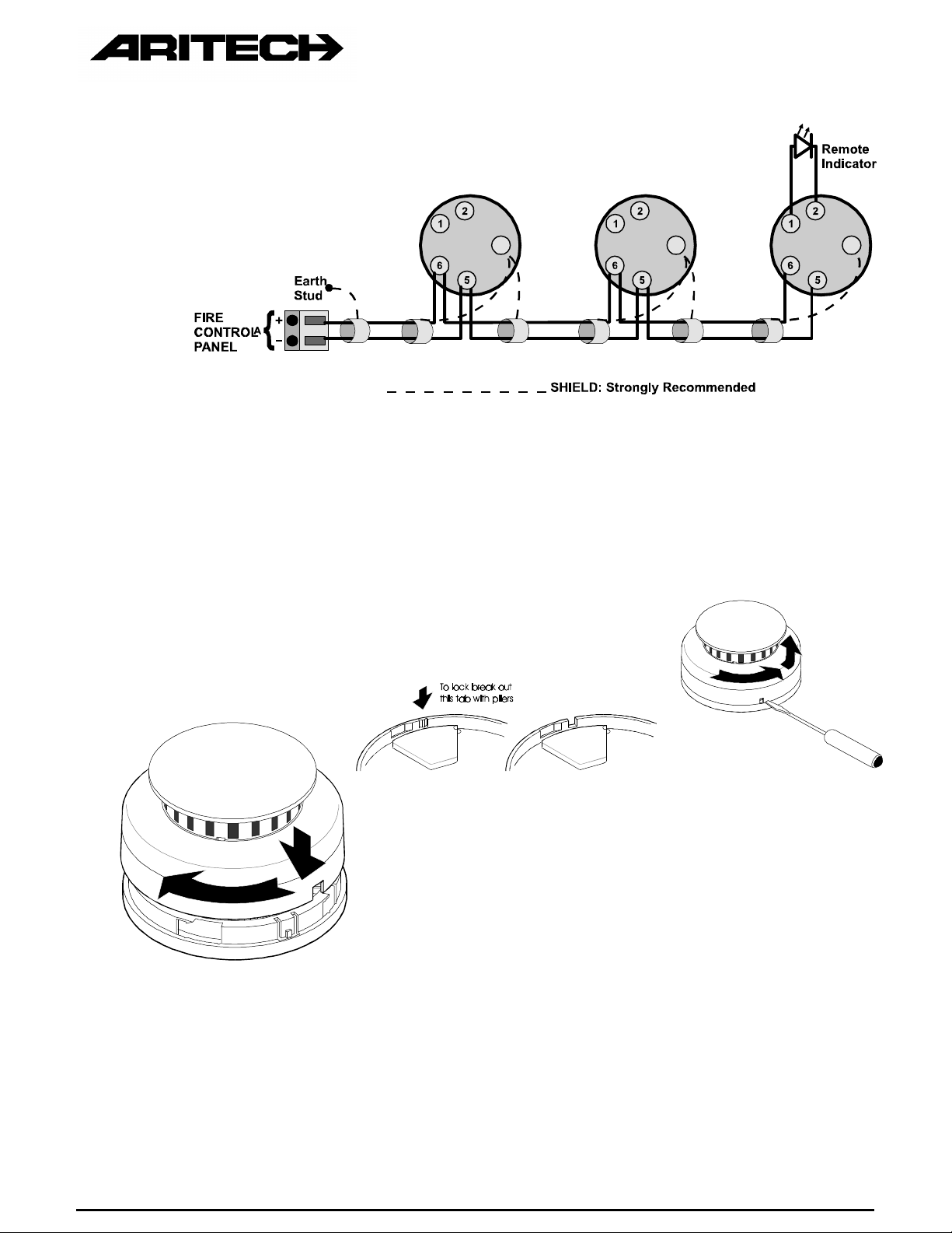
Figure 2: Class B Wiring
Figure 3 Figure 4 Figure 5
Page 11
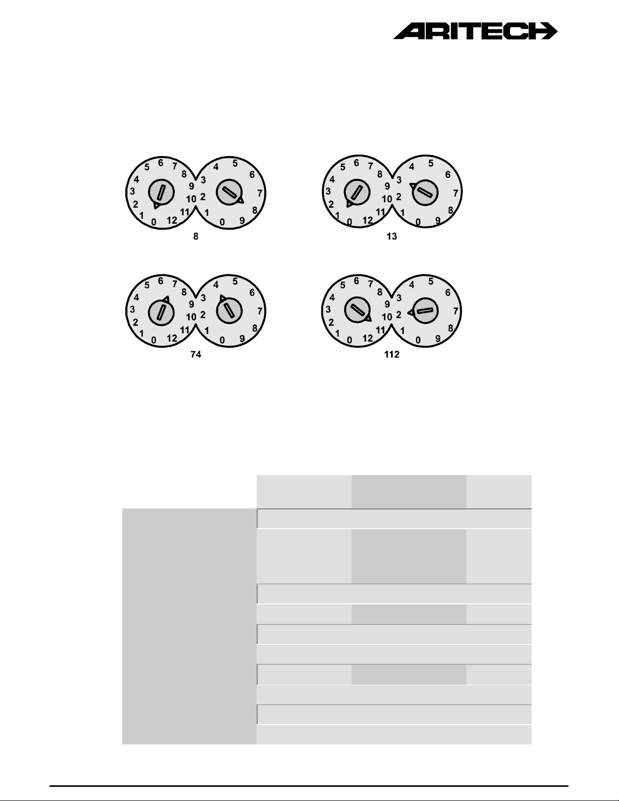
2.2.3 Addressing
To install a detector address (see Figure 6), use a screw driver to adjust the two rotary
switches on the back of the sensor. Set the left rotary switch (0 through 12) for the 10's
and 100's digit and the right rotary switch for the 0 through 9 digit.
Figure 6 : Address Setting for 2000 Series Fire Sensors
2.2.4 Technical Data
Operating Voltage 17 - 28 V DC
Current Consumption :
quiescent @ 24V
Remote Indicator max. 4Ma
Max. Air Flow 10 m/s
Relative Humidity 0 - 95% no condensation
IP - Rating IP43
Ionisation Source 0.9 µCi Am 241
2000
IONISATION
LED = 2mA
2000
OPTICAL
< 150 µA
7-Segment = 2mA
2000
HEAT
Operating Temperature -20 to +70ºC (no icing)
Storage Temperature -30 to +85ºC
Dimensions H = 5 cm Ø =10 cm
Page 12

2.2.5 7-Segment Indication
The 207X models have a 7-segment display. The information displayed depends on the
panel the sensors are connected to.
When the 2000 Series Sensors are being installed with the Aritech FP2000 Fire Panel,
the following indications are available:
Figure 7 : Indications on 7-Segment Display
Page 13
Notes: (Combined with FP2000)
• At the fire panel this information can be programmed to be always available (On) or
only when the sensor is being polled (Blinking).
• When the complete zone is disabled, nothing will appear on the 7-segment display of
the disabled devices.
• The maximum number of 7-segment displays active at the same moment can be
programmed at the panel (in ‘On’ mode).
• The test conditions mentioned above are tests initiated at the panel and not from the
sensor itself (see paragraph 2.2.6).
2.2.6 Diagnostics and Sensitivity Test Modes
Diagnostic and sensitivity test modes are available on the 2000 Series Detectors. The
2000 Series Smoke Detectors provide obscuration or temperature information to the Fire
Panel. Obscuration or temperature is determined by the number of counts received at
the Fire Panel when a 2000 Series Detector is polled.
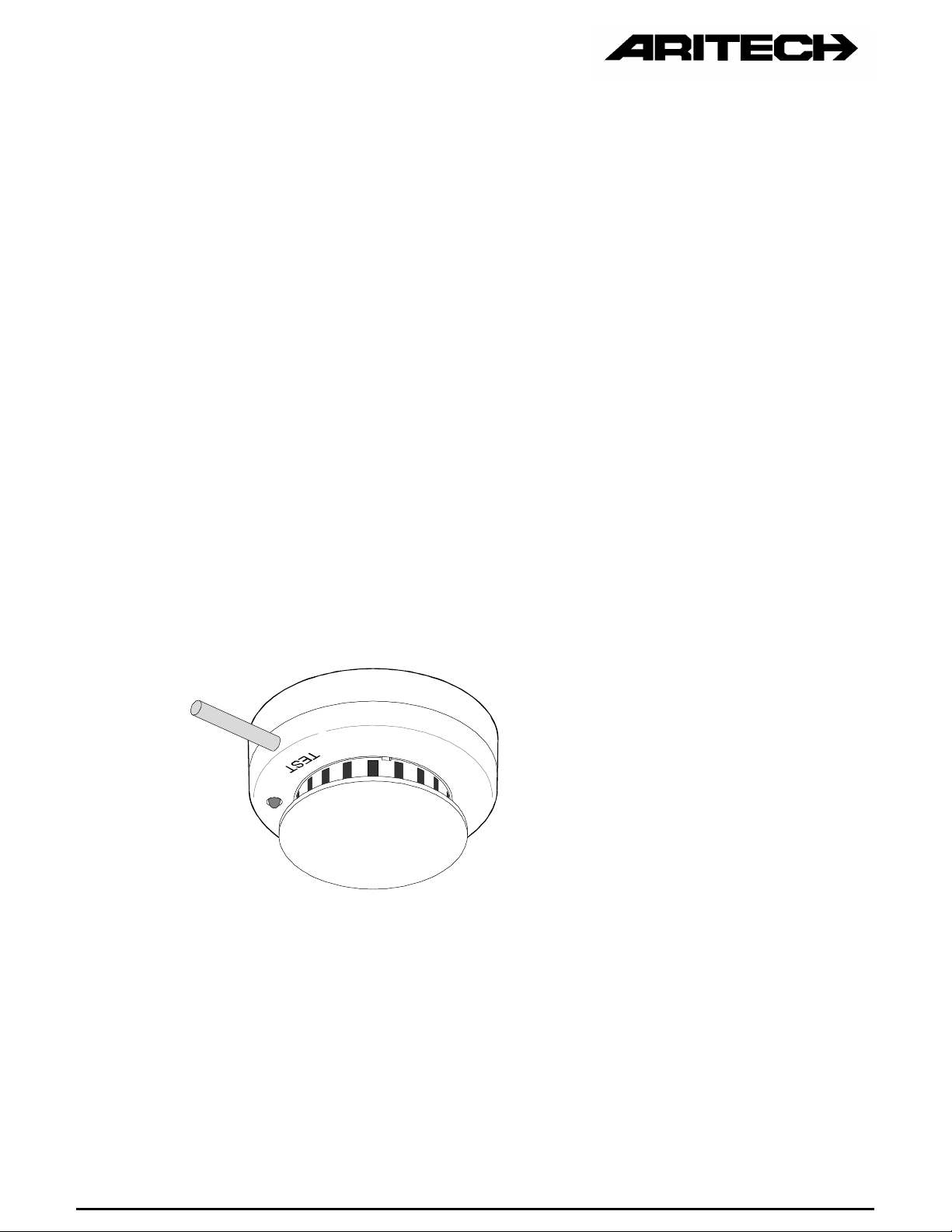
The DP2071, DI2072 and DT2073 models have a seven segment display that allows
sensitivity, diagnostic and address data to be displayed at the detector head. Holding a
magnet near the integral reed switch (Figure 8) will initiate the diagnostic routine at the
Fire Panel.
Figure 8 : Initiating the Diagnostic Routine
The following sequence will be displayed on the sensor :
First, the address of the sensor will be displayed (e.g. 35), followed by the real-time
value (e.g. 56), which is displayed twice.
Page 14

Figure 9 : Sequences Displayed on 7-Segment Display
2.2.7 Testing, Maintenance and Cleaning
All 2000 Series Smoke Detectors are shipped with a plastic dust cover for use in areas
where construction is on-going. Smoke Detectors will not work with the dust cover in
place. Remove the dust cover when installation is completed, prior to testing.
All Smoke Detectors should be tested in place at least annually or according to local
regulations, to ensure smoke entry into the sensing chamber and alarm response. If
canned smoke (test aerosol) is used, carefully follow the manufacturer's directions to
avoid damage to the detector.
Test Heat Sensors by using a hot air gun (Figure 10A). Aim at heat sensor from 15 to
25cm away. Be careful not to melt the plastic.
The sensing chamber of the 2000 Series Photo-electric Detector unsnaps for easy field
cleaning and service (Figure 10B). Whenever the diagnostics indicates that cleaning is
necessary, remove the photoelectric detector cap, snap off and throw away the optical
block chamber (Figure 10C). Then blow off the optical block base and snap a new
optical block chamber back in place, replace the cap and verify sensitivity.
For 2000 Series Ionisation Detectors, remove the detector cover and clean the sensing
chamber and chamber screen whenever diagnostics indicate cleaning is necessary
(Figure 10D). Use a vacuum and/or filtered compressed air to remove dirt from the
chamber's interior. After cleaning, replace the chamber screen and detector cover and
verify sensitivity. If sensitivity remains out of limits, replace the sensor and return the
removed one to the manufacturer for cleaning and re-calibration.
Ionisation Sensors contain a radioactive source and should not be opened any further
than to clean as per above.
Page 15

A
B
Figure 10 : Testing, Maintenance and Cleaning
C
D
Page 16

2.3 MANUAL CALL POINT (MCP) DM2000 DM2010 DM2020
INSTALLATION
Figure 11 : Wiring Diagram for DM20X0
Page 17

ADDRESSING
Addressing is by means of a DIL-switch on the rear side of the MCP: ON = 0; OFF = 1
Address Switch Address Switch Address Switch Address Switch
12345678 12345678 12345678 12345678
1 00000001 33 00110011 65 01100101 97 10010111
2 00000010 34 00110100 66 01100110 98 10011000
3 00000011 35 00110101 67 01100111 99 10011001
4 00000100 36 00110110 68 01101000 100 10100000
5 00000101 37 00110111 69 01101001 101 10100001
6 00000110 38 00111000 70 01110000 102 10100010
7 00000111 39 00111001 71 01110001 103 10100011
8 00001000 40 01000000 72 01110010 104 10100100
9 00001001 41 01000001 73 01110011 105 10100101
10 00010000 42 01000010 74 01110100 106 10100110
11 00010001 43 01000011 75 01110101 107 10100111
12 00010010 44 01000100 76 01110110 108 10101000
13 00010011 45 01000101 77 01110111 109 10101001
14 00010100 46 01000110 78 01111000 110 10110000
15 00010101 47 01000111 79 01111001 111 10110001
16 00010110 48 01001000 80 10000000 112 10110010
17 00010111 49 01001001 81 10000001 113 10110011
18 00011000 50 01010000 82 10000010 114 10110100
19 00011001 51 01010001 83 10000011 115 10110101
20 00100000 52 01010010 84 10000100 116 10110110
21 00100001 53 01010011 85 10000101 117 10110111
22 00100010 54 01010100 86 10000110 118 10111000
23 00100011 55 01010101 87 10000111 119 10111001
24 00100100 56 01010110 88 10001000 120 11000000
25 00100101 57 01010111 89 10001001 121 11000001
26 00100110 58 01011000 90 10010000 122 11000010
27 00100111 59 01011001 91 10010001 123 11000011
28 00101000 60 01100000 92 10010010 124 11000100
29 00101001 61 01100001 93 10010011 125 11000101
30 00110000 62 01100010 94 10010100 126 11000110
31 00110001 63 01100011 95 10010101 127 11000111
32 00110010 64 01100100 96 10010110 128 11001000
Page 18

2.4 ISOLATOR IU2016
GENERAL
An isolator is a “device” which prevents a loop going down completely when a short circuit in
that loop occurs. When isolators are used, only the devices between two isolators will go down.
The IU2016 can be placed in the loop and is completely transparent for the protocol (in normal
condition). No address setting is required.
High-end fire panels, like FP2000, have built-in isolators per loop. This means that no isolators
have to be placed at the beginning and end of the loop.
INDICATORS
The yellow LED will start blinking when the isolator goes active i.e. when one side is isolated.
The short-circuit will always be located between two active isolators or between one active
isolator and the panel
INSTALLATION
The Isolator is fitted into the Isolator Mounting Base DB2003.
There are four single terminals, namely:
1. (+) IN : Line in
2. (+) OUT : Line out
3. (-) : Common negative
4. Single terminal : This terminal is intended as a through connection point for cable
shields or for an earth connection.
Page 19
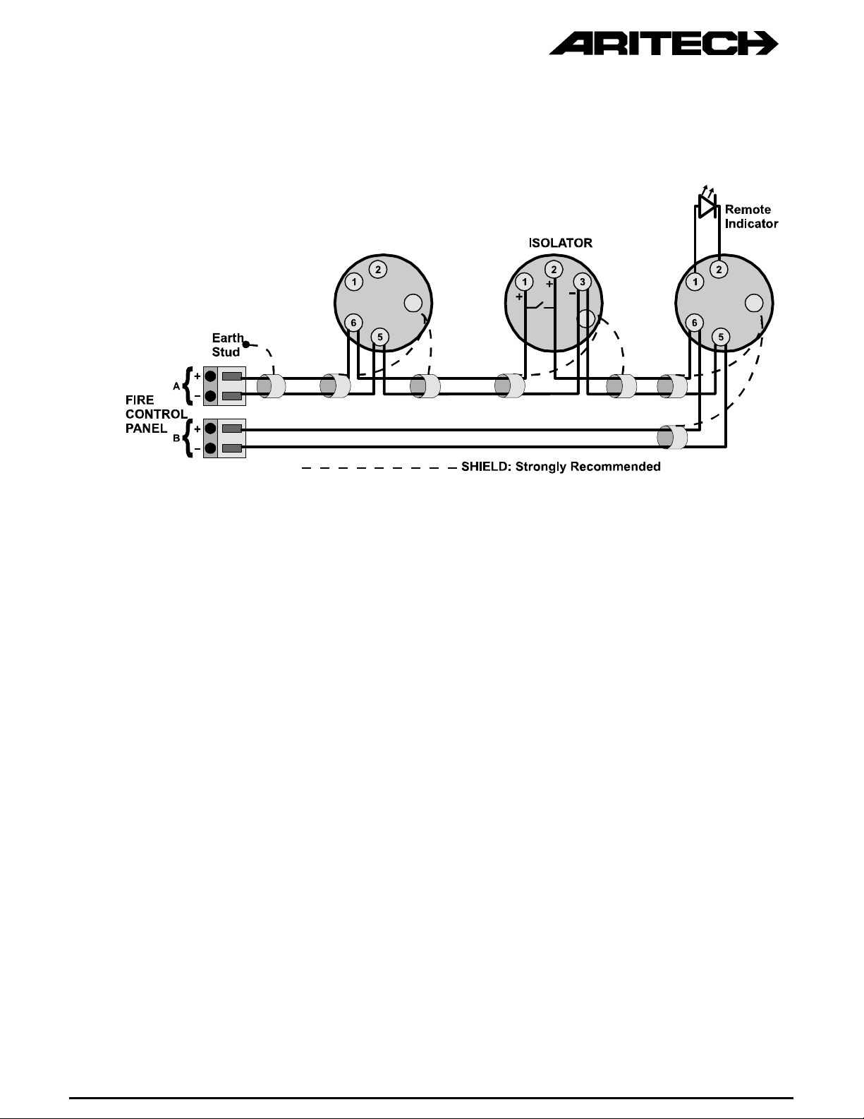
Isolators are - unlike the other 2000 Series devices - polarity sensitive. The connection must be
as follows:
Figure 12 : Class A Loop with Isolator IU2016
Note : According to the EN54-directive, isolators should be placed at least every 32 devices.
The use of isolators per zone is recommended.
Please consult local regulations and follow Fire Brigade requirements.
TECHNICAL DATA:
Operating Voltage...........................................17 - 38 V
Non - isolated current......................................<205 µA
Isolated current...............................................<420 µA
Line resistance non-isolated...........................< 1 Ohm
Line resistance isolated ..................................> 33 K ohm
Switching times non-isolated to isolated.........< 5 ms
Switching time isolated to non-isolated...........< 3.1 s once fault is removed
Operating temperature ....................................-20 to + 70 ºC (non condensing)
Storage temperature.......................................-30 to + 85 ºC
Relative humidity.............................................0 - 95 %
Page 20

2.5 FIRE MONITORING CONTROLLERS
2.5.1 Zone Monitoring Unit IU2051
GENERAL DESCRIPTION
The IU2051 can be used to connect conventional detectors, fire beams, etc. on the
analogue loop. It is important to note that the total current load of the conventional loop
must not exceed 3.5 mA. This is typically 30 detectors.
The PCB has to be put in a housing, according to environmental conditions.
INDICATORS
Yellow LED : Indicates an open circuit or short on the two-wire
conventional loop.
Ind +/- connectors : An extra LED can be connected to indicate a Fire Alarm
condition on the conventional loop.
ADDRESS SETTING
Please refer to paragraph 2.2.3.
TECHNICAL DATA
Operating voltage: ......................................20-28V at the communication loop terminals
Total standby current:.................................<7.5mA, 4.5mA typical (no conventional
detectors connected) at the communication
loop terminals
Maximum alarm current: .............................< 60 mA at communication loop
Maximum no. of conventional detectors: ....30. Do not exceed 3.5 mA + EOL load current
Maximum capacitance:...............................1 µF
Maximum line length:..................................not to exceed 2km or not greater than
100 Ohms
End-of-Line resistor value:..........................10 k ± 5%, 1/4 W
Supply Voltage conventional loop:.............. 17 - 25 V DC
Zone impedances @ 24V: Short circuit:.....< 120 Ohms
Fire: .................120 - 1 K
Quiescent: .......1K - 26 K
Open circuit: ....> 26 K
Page 21

Extra remote output:...................................current limited at 4.5 mA
Operating & Storage temperatures:............see Sensors (paragraph 2.2.4)
Mounting holes:…………………..................4mm diameter
Physical dimensions & mounting holes:......dimensions in mm
Page 22

INSTALLATION
Figure 13 : Wiring Diagram for Zone Monitoring Unit
Page 23

Note: Where (non-addressable) intrinsically safe detectors are to be used, the Zener
barrier must be placed in the safe area adjacent to the hazardous area.
2.5.2 Indicating Circuit Controller IU2080
GENERAL DESCRIPTION
The IU2080 provides an interface between the two wire multiplexed ring circuit and local
supply loop sounders and strobes with their associated user supplied external power
supply. The local supply loop circuit can be selected for a 12V or 24V application. The
selection is done by the S2 switch located on the board. If the switch is closed, the loop
is set to the 12V application and if the switch is open the loop is set to the 24V
application. The external power supply provides the power to drive the sounders and
strobes. A number of devices totalling up to 3A may be connected to the sounder spur
(750 mA in applications requiring AFNOR approvals).
The ICC monitors the local power supply for a low voltage condition and the external
fault relay contacts (via fault +-ve) for an open condition. An end of line resistor is used
to ensure that the local supply loop is intact. The ICC monitors for loop shorts as well as
for loop open circuits via this resistor. Moreover, the ICC can provide a means for EOL
monitoring via a Z-style connection back to the ICC itself.
The PCB has to be put in a housing, according to environmental conditions.
INDICATORS
The IU2080 contains a red LED that will light when the relay is in a position to cause the
sounders and sirens to be energised. The green LED indicates that the external power
supply voltage is present and greater than approximately 8 volts.
ADDRESSING
The address of the ICC is set by a dip switch on the ICC circuit board. The decimal
address of the ICC must be converted to a binary number to set the dip switch. Please
refer to paragraph 2.3 (MCP) for the complete table.
TECHNICAL DATA
Operating voltage ........................... 17 - 28V (at the communication loop terminals)
Total standby current...................... < 350 mA (< 200 µA typical)
Maximum loop alarm current........... < 3.5 mA
End of line resistor value ................ 10 K 1/4W, 5%
Bell loop impedances at 24V:
Short circuit..................................... < 3.3 K
Quiescent ....................................... 3.3 K - 13.0 K
Open circuit..................................... > 13.0 K
Local power supply, low voltage detection:
12V supply...................................... <10.2V
24V supply...................................... <20.4V
Page 24

Local supply current (standby)........ <11.0mA @ 24 VDC
Local supply current (alarm) ........... <72.0mA @ 24 VDC plus bell loop load current
Supervisory voltage........................ approx. 2.2 VDC (inverted)
Bell loop voltage in alarm................ 12 or 24 VDC
Fuse rating...................................... 3A
Physical dimensions ....................... See paragraph 2.5.1, Zone Monitoring Unit
Mounting holes ............................... See paragraph 2.5.1, Zone Monitoring Unit
Operating & storage temperature ... See paragraph 2.2.4
INSTALLATION
Figure 14 : Location of Jumpers and Connectors on the PCB
Page 25

Figure 15: Style Y Operation without Power Supply Trouble Relay
Page 26
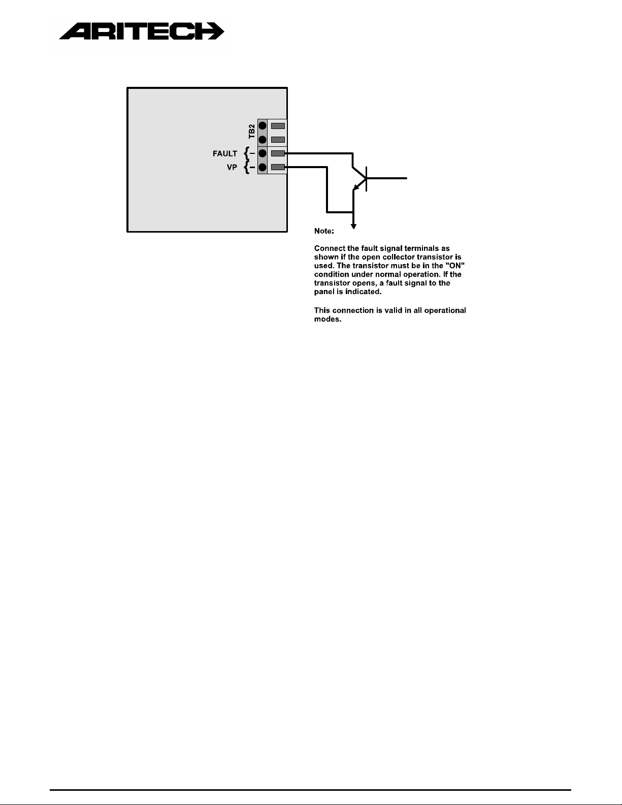
Figure 16 : Fault Signal Indication with Open Collector Driver
Page 27

Figure 17 : Style Y Operation with Power Supply Trouble Relay
Page 28

Figure 18 : Style Z Operation without Power Supply Trouble Relay
Page 29
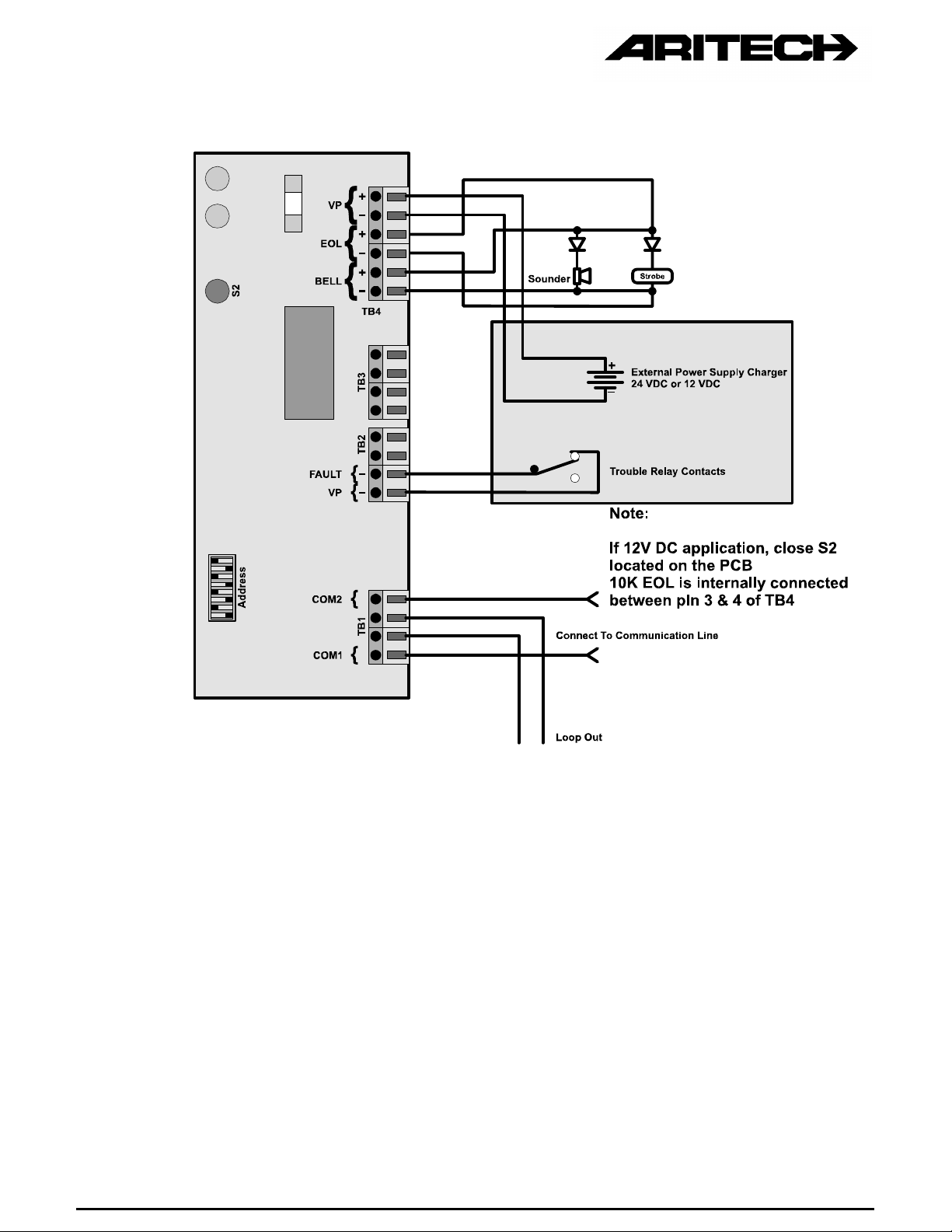
Figure 19 : Style Z Operation with Power Supply Trouble Relay
Page 30
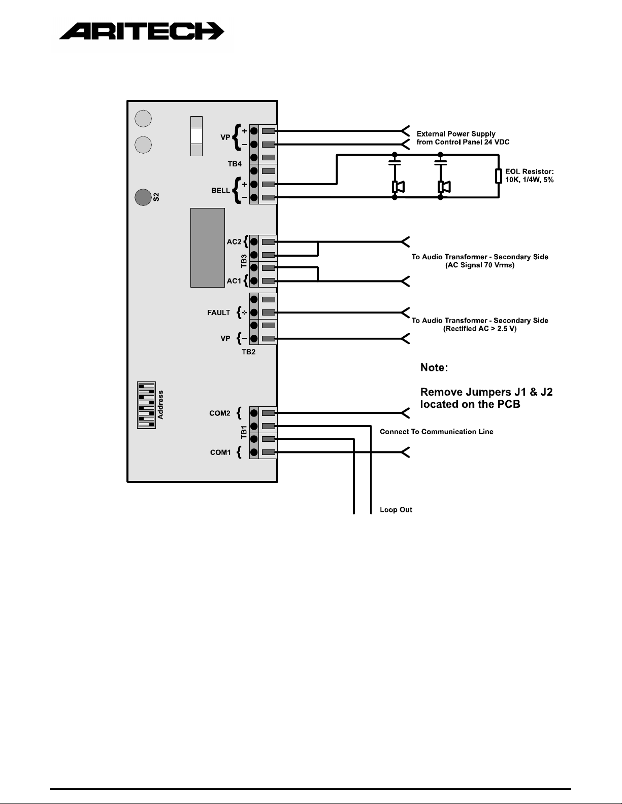
Figure 20 : AC Operation
Page 31

2.6 INPUT / OUTPUT UNITS
GENERAL
The Aritech 2000 Series input-output modules allow for connecting an external signal (input) by
a voltage free contact for further processing in the Fire panel . These inputs are supervised and
faults can be signalled at the panel. Furthermore, relay contacts (output) can be used for
triggering devices, external to the loop.
All 2000 Series IO-modules are loop powered (no additional power supply required).
The PCB has to be put in a housing, according to environmental conditions.
Depending on the amount of supervised inputs and outputs, the following models are available:
IO2034 : 4 Inputs / 4 Outputs module
IO2032 : 2 Inputs / 2 Outputs module
IO2031 : 2 Inputs / 1 Output module
IO2014 : 4 Inputs module
INDICATORS
A yellow LED indicates a fault condition in one of the supervised inputs. The definition of this
fault condition (open, short, open or short) must be programmed at the panel. The indication
stays until the panel is reset.
ADDRESSING
The address of a Input / Output Unit is set by means of two rotary switches on the unit. Please
refer to paragraph 2.2.3 on how to set the address.
TECHNICAL DATA
Operating voltage .........................................17 -28V
Total standby current....................................<250 µA
Typical standby current.................................<200 µA
Maximum line length.....................................not to exceed 100 m
Outputs:........................................................2.0 Amps max. at 30 VDC
0.3 Amps max. at 125 VAC
Inputs :
Input Loop Impedance
(220K EOL included)
Open - 330K Open (open circuit)
330K - 130K Passive (contact open)
Reported To Panel :
130K - 8K Active (contact closed)
8K - short Short (short circuit)
Page 32

Physical dimensions & mounting holes (mm):
Page 33

INSTALLATION:
Page 34

3. LOOP LOAD CALCULATIONS
3.1 GENERAL
When designing a Series 2000 system it is important to calculate the designed loop
configuration to ensure that it operates within the minimum and maximum voltage parameters
under worst case voltage and current conditions.
The low voltage limit is normally 20 volt DC for systems that include Zone Monitoring Units and
for systems without such units it is 17 volt DC.
The voltages mentioned only refer to the minimum DC voltage level, the AC voltage level must
be maintained at 5 to 9 volt above the DC level.
The calculation procedure and expressions shown in the following paragraphs give a rough
method of checking whether the DC conditions are satisfied.
The calculations are based on the DC voltage only and the attenuation of the AC voltage
signals is theoretically relative to that of the DC voltage. In most cases, the AC voltage will be
within specification when the DC voltage is within specification limits, provided that the AC
voltage level is well above the minimum DC level (5 volt) to begin with.
3.2 CALCULATION PROCEDURE
1. Calculate the total quiescent (standby) current for the loop devices using Table 2.
2. Calculate the worst case condition for additional alarm and LED current using Table
3.
Notes :
• The ‘worst case’ condition should still be considered as a ‘realistic’ condition,
taking into account the physical location of the sensor, remote indicators and
so on. In most of the applications, 10 sensors in alarm at the same moment
(per loop) is a good indication.
• In some panels (like FP2000), the max. number of LED’s in alarm per loop at
the same time can be programmed.
3. Determine the total loop resistance, using Table 4.
• The cable values given are "per core", therefore for a two core cable the
resistance must be multiplied by two.
• The 10 ohm source impedance is related to the FP2000.
4. Multiply the total current and the total resistance and subtract the result from the
central control equipment loop voltage. This will give the minimum voltage that a
device in the worst possible position on the loop can experience under power fail
conditions.
Page 35

3.2.1 Standby Current
LOOP 1
STANDBY CURRENT
Device Code Number of
Devices
IONISATION DI2052 0,00025
DI2072 0,00025
OPTICAL DP2051 0,00025
DP2071 0,00025
HEAT DT2053 0,00025
DT2073 0,00025
MCP DM2000 0,00025
ZONE MONITOR IU2051 0,0045
IND. CIRCUIT CONTROL IU2080 0,00035
4I / 4O IU2034 0,00025
2I / 2O IU2032 0,00025
2I / 1O IU2031 0,00025
4I IU2014 0,00025
Standby
Current (A)
Total Standby
Current (A)
Table 2 : Device Quiescent Current
3.2.2 Alarm Current
LOOP 1
ALARM CURRENT
Define numbers of sensors that
can go into alarm at the same time
Table 3 : Device Alarm Current
Number of
Devices
10 0.004 0.04
Alarm
Current (A)
Total Alarm
Current (A)
Page 36

3.2.3 Loop Resistance
LOOP 1
RESISTANCE
Part Code Resistance Number of
Devices
PANEL SOURCE FP2000 10 1 10
ISOLATORS IU2016 1
CABLE 2L1.0 MICC 0.017
(Ohm/m/CORE) 2L1.5 MICC 0.011
2L2.5 MICC 0.1168
FP200 1.0 0.0181
FP200 1.5 0.0121
FP200 2.5 0.0074
WS104 0.05
WC104 0.020635
Table 4 : Resistance
Total Resistance
(ohm)
Calculation for Minimum Device Voltage (V
TOTAL CURRENT : I (sum of quiescent and alarm current)
TOTAL RESISTANCE : R
LOOP VOLTAGE : V ( e.g. FP2000 : 29 V )
V
V
V
min
min
min
= V — (I x R)
> = 17 volt — no Zone Monitoring Units
> = 20 volt — with Zone Monitoring Units
) Under Worst Case Conditions:
min
 Loading...