

Page 1
Servicing
Instructions
Type CBoilers
G.C.N: 41- 116-05
LEAVE THESE INSTRUCTIONS
WITH THE END-USER
Country of destination: GB
Page 2

2
1. SERVICING INSTRUCTIONS
1.1 REPLACEMENT OF PARTS
1.2 TO GAIN GENERAL ACCESS
- Removing the front panel
- Removing the sealed chamber front cover
- Removing the side panels
1.3 ACCESS TO THE COMBUSTION CHAMBER
- Removing the combustion cover
- Removing the burner and jets
- Removing the electrodes
- Removing the main heat exchanger
- Removing the air pressure switch
- Removing the fan
1.4 SERVICING AND REMOVAL OF THE GAS VALVE
- Setting the gas pressures
- Removing the spark generator
- Removing the gas valve
1.5 ACCESS TO THE WATER CIRCUIT
- Removing the pump pressure switch
- Removing the safety valve
- Removing the automatic air vent
- Removing the pump
- Removing the pressure gauge
- Removing the expansion vessel
- Removing the overheat thermostat
- Removing the frost thermostat
- Removing the regulation thermostat
1.6 ACCESS TO THE CONTROL SYSTEM
- Checking the fuses
- Removing the P.C.B.s
2. FAULT FINDING
2.1 FAUL T FINDING GUIDE (FLOW-CHARTS)
3. ELECTRICAL DIAGRAMS
4. SHORT SPARE PARTS LIST
TABLE OF CONTENTS
Page 3
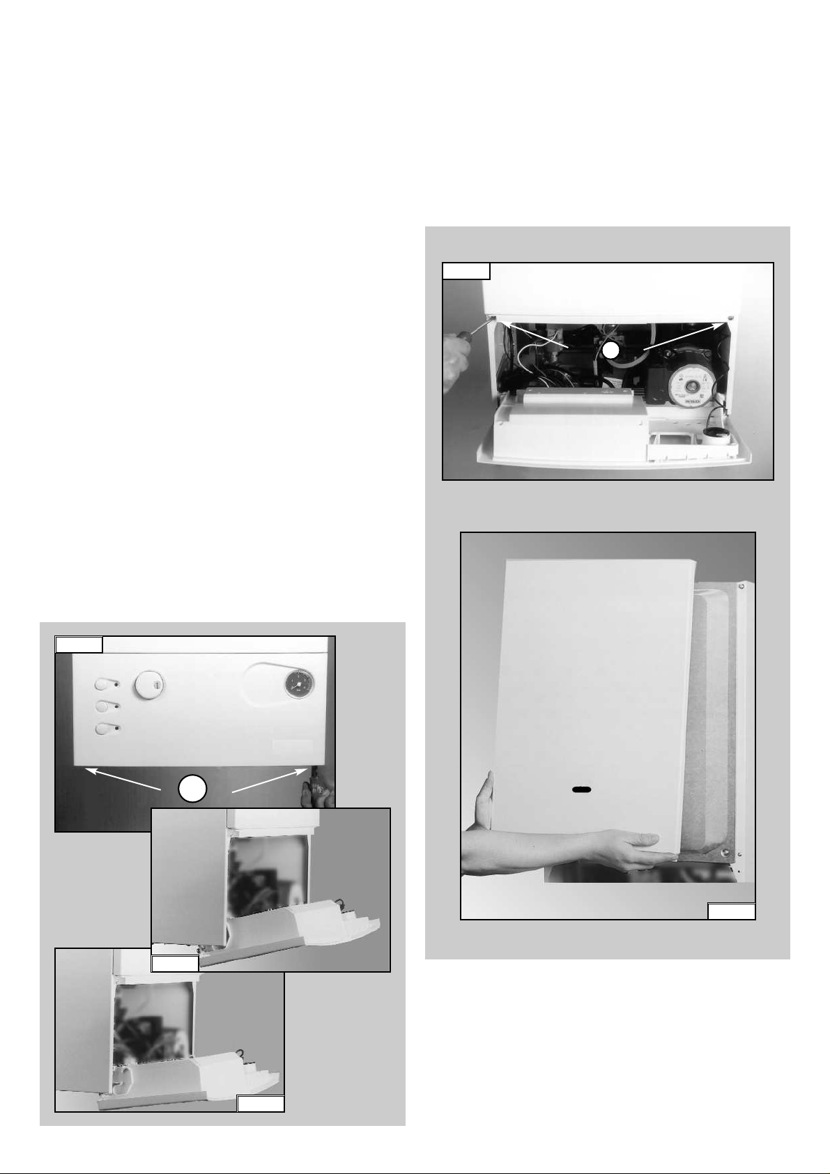
2. The control panel moves downward and when pulled forward,
rotates on two lateral hinges; the panel stays in a semihorizontal position, which allows access to the inner parts of
the boiler (FIG. 1.2);
3. In order to increase the manouvering space, it is possible to
raise the control panel and rotate it to a fully horizontal position
(FIG. 1.3);
4. Remove the screws “B” from the front panel bottom lip
(FIG. 1.4);
5. Lift the front panel up and forward from the raised screws at the
the top of the casing (FIG. 1.5).
FIG. 1.4
B
FIG. 1.5
3
1. SERVICING INSTRUCTIONS
The life of individual components varies and they will need
servicing or replacing as and when faults develop.
The fault finding sequence chart in chapter 2 will help to locate
which component is the cause of any malfunction, and instructions
for removal, inspection and replacement of the individual parts are
given in the following pages.
1.1 REPLACEMENT OF PARTS
1.2 TO GAIN GENERAL ACCESS
All testing and maintenance operations on the boiler require the
control panel to be lowered. This will also require the removal of
the casing.
1.2.1 Removing the front panel
1. Loosen the fastening screws “A”of the control panel located on
the lower part of the panel itself. (FIG. 1.1);
A
FIG. 1.3
FIG. 1.1
FIG. 1.2
To ensure efficient safe operation, it is recommended that the
boiler is serviced annually by a competent person.
Before starting any servicing work, ensure both the gas and
electrical supplies to the boiler are isolated and the boiler is
cool.
Before and after servicing, a combustion analysis should be made
via the flue sampling point (please refer to the Installation Manual
for further details).
After servicing, preliminary electrical system checks must be
carried out to ensure electrical safety (i.e.polarity, earth continuity,
resistance to earth and shor t circuit).
Page 4
4
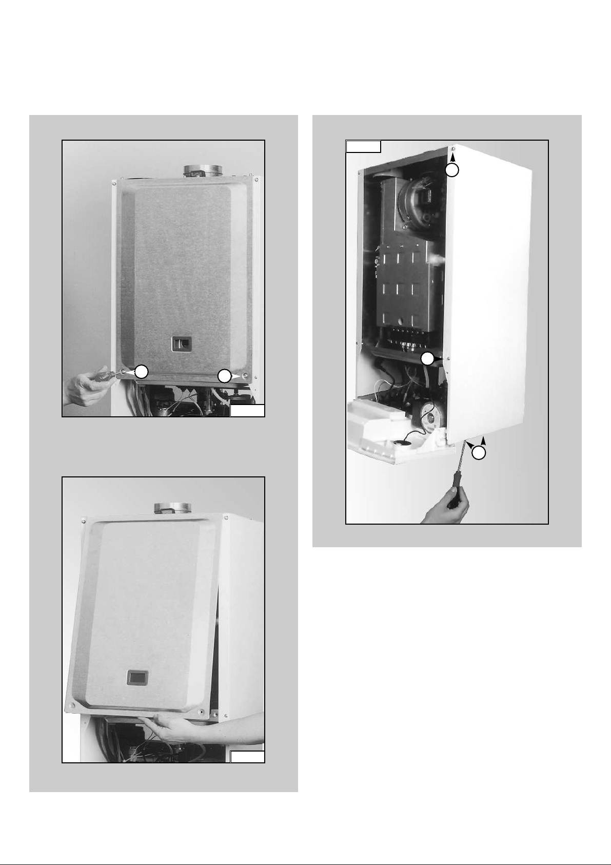
1.2.2 Removing the sealed chamber front cover
1. Remove the screws “C” (FIG. 1.6);
2. Lift the sealed chamber front cover from the locating pins
(FIG. 1.7).
FIG. 1.6
C
C
FIG. 1.7
1.2.3 Removing the side panels
1. Remove the four screws “D” for each side panel (FIG.1.8);
2. Pull the panel away from the boiler at the base, then lift the
panel up and remove from the boiler.
D
D
D
FIG. 1.8
Page 5
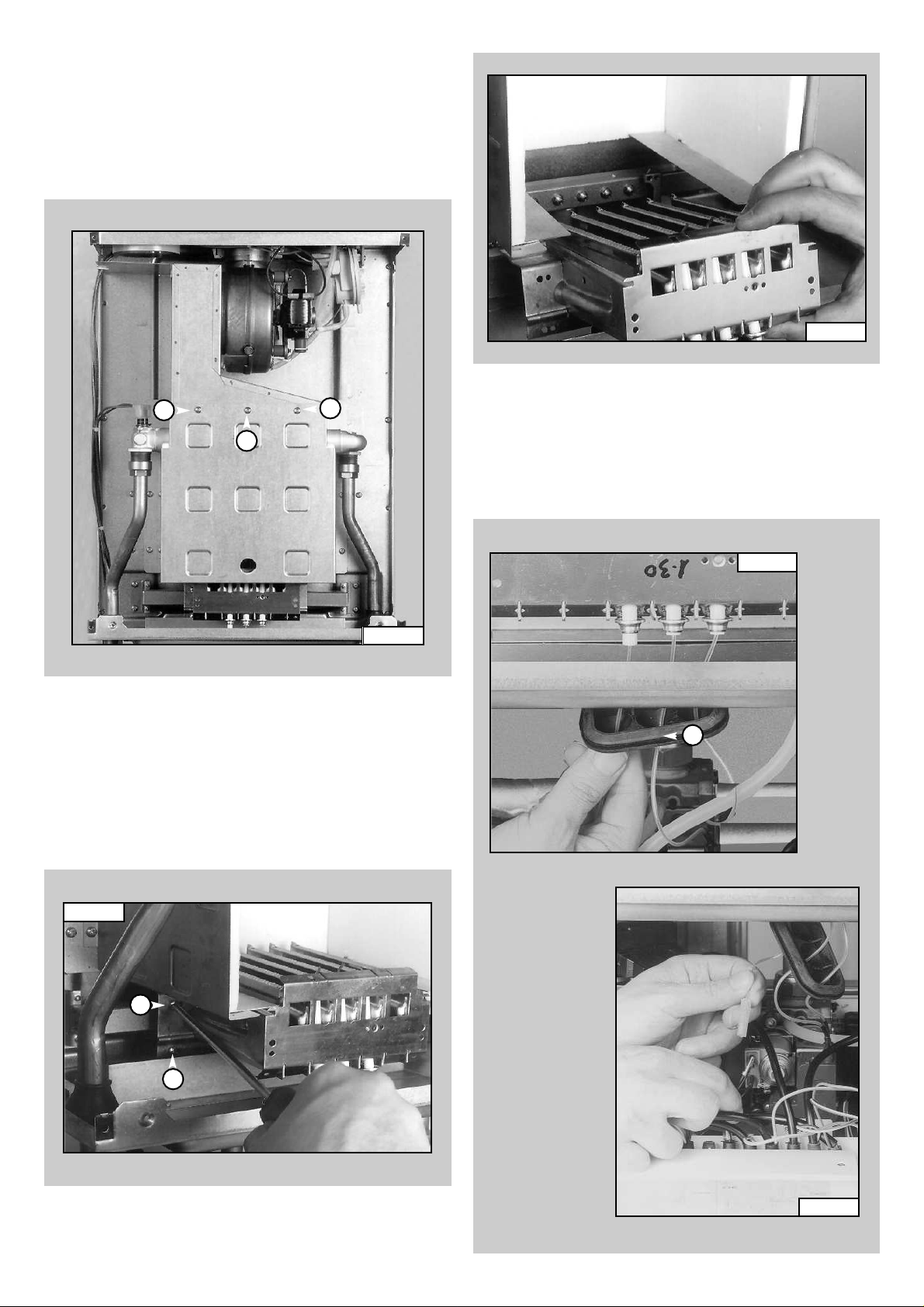
1.3.3 Removing the electrodes
Before carrying out this procedure, unscrew and slide the
burner forward (see previous section).
1. Remove rubber gasket “G” (FIG.1.12);
2. To remove the detection electrode disconnect the cable
at its connection point close to the P.C.B. (FIG. 1.13);
FIG. 1.12
G
FIG. 1.13
1.3.2 Removing the burner and jets
1. Remove the screws “F” from the burner (FIG. 1.10);
2. Remove the burner (FIG. 1.11);
3. Disconnect the electrodes (see section 1.3.3);
4. Remove the jets using a No. 7 socket spanner;
5. Replace in reverse order.
5
1.3.1 Removing the combustion cover
1. Remove the screws “E”(FIG. 1.9);
2. Lift off the combustion cover.
1.3 ACCESS TO THE COMBUSTION CHAMBER
E
E
E
FIG. 1.9
FIG. 1.10
Fig. 1.11
F
F
Page 6

6
3. Remove screw “H” (FIG. 1.14);
4. Gently slide the electrode downward (FIG. 1.15).
To replace, repeat the steps in reverse order, paying
particular attention to the following:
a - Centre the electrode in the positioning hole carefully,
otherwise the electrode may break;
b -Ensure that the left hand and right hand electrodes are
located the correct way round (facing each other), to
give the correct spark gap;
c -Check that the cables have been connected correctly;
d -Check that the rubber gasket covers the cable/ electrode
connection point completely.
FIG. 1.14
FIG. 1.15
H
1. Drain the boiler of water;
2. Release the overheat thermostat sensor “I” (FIG. 1.16);
3. Release the two connection nuts “J” connecting the
exchanger to the flow and return pipes (FIG. 1.17);
4. Remove the heat exchanger by sliding forward (FIG.
1.18).
1.3.4 Removing the main heat exchanger
FIG. 1.17
J
Fig. 1.16
I
FIG.1.18
Page 7
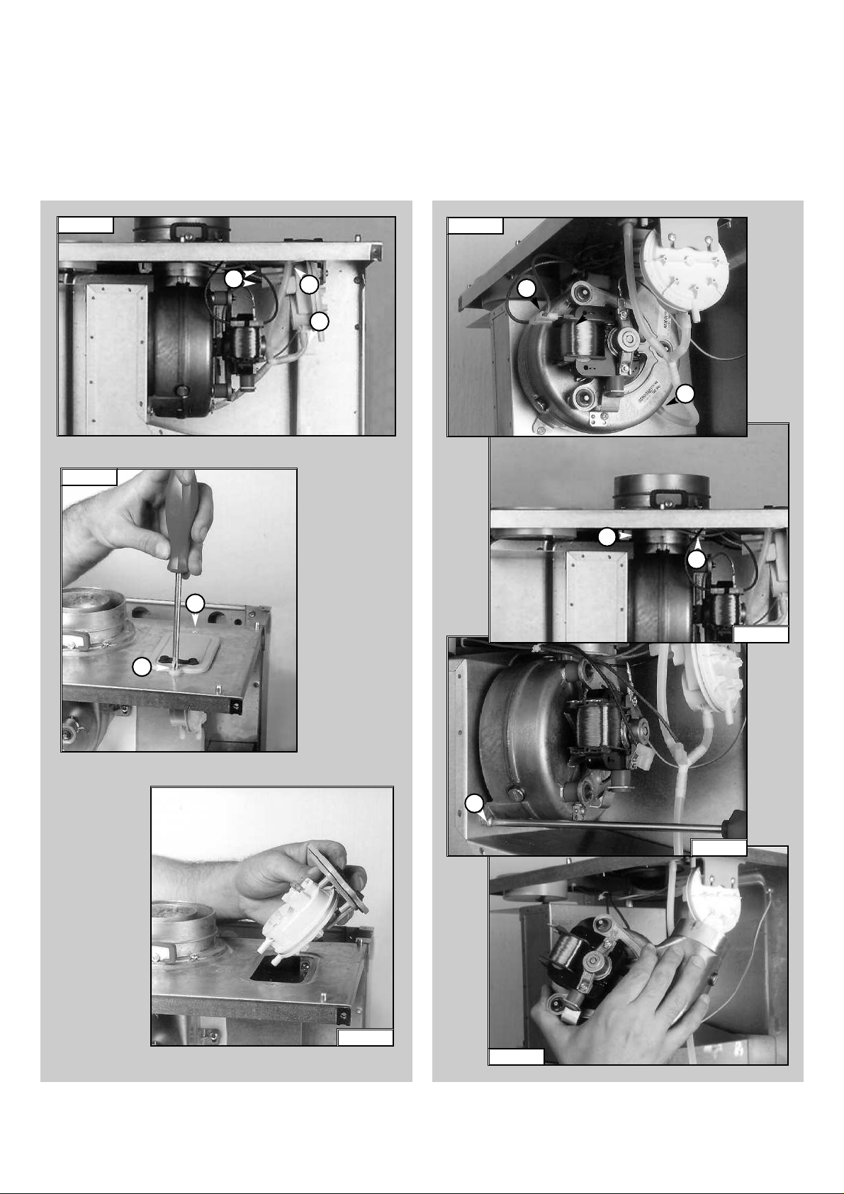
1. Disconnect electrical connections “N”and silicon pipe “O”
(FIG.1.22);
2. Remove screw “P” and remove the fan collar clamp “Q”
(FIG.1.23);
3. Remove screws “R” (FIG.1.24);
4. Remove fan and mounting plate (FIG.1.25).
1.3.6 Removing the fan
1. Disconnect the electrical connections “K” and silicone
pipes “L” from their connection points (FIG. 1.19);
2. Remove screws “M” on the top of the sealed chamber
(FIG. 1.20);
3. Lift out the air pressure switch (FIG. 1.21);
4. Unscrew to remove the switch from the plate.
FIG. 1.20
FIG. 1.19
7
1.3.5 Removing the air pressure switch
L
L
K
M
M
FIG. 1.21
FIG. 1.24
R
FIG. 1.23
P
Q
FIG. 1.22
N
O
FIG. 1.25
Page 8
8
1.4 SERVICING AND REMOVAL
OF THE GAS VALVE
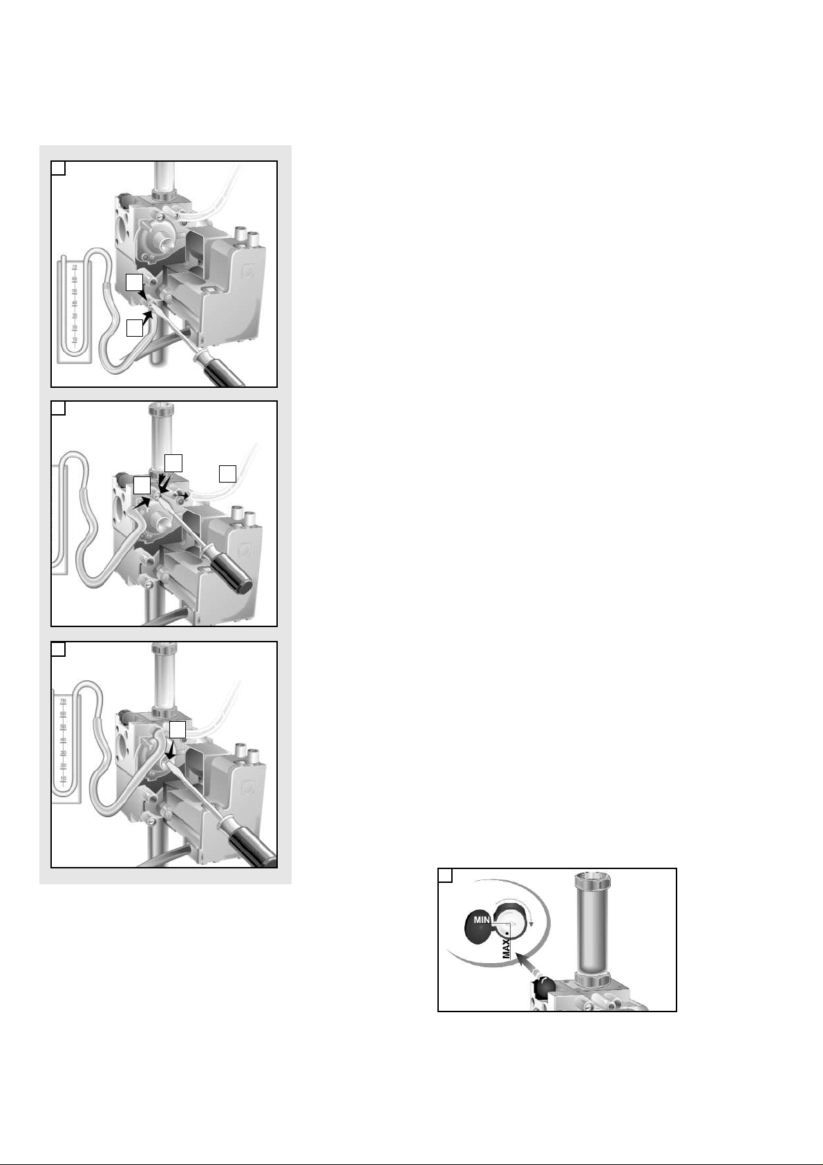
1.4.1 Setting the gas pressures
1
2
3
A
B
C
F
D
Setting the maximum power of the boiler
1. Check that the supply pressure to the gas valve is a minimum of 20 mbar
for natural gas.Turn off the gas supply at the isolation point under the
boiler
2. To do this, slacken the screw “A”.
Fit the pipe of the pressure gauge to the inlet pressure test point of the gas
valve “B”.
T urn on the gas suppl y at the isolation point under the boiler and with
the boiler running, read the inlet working pressure on the gauge.
When you have completed this operation, turn off the gas supply at the
isolation point under the boiler, remove the pressure gauge and tighten
the screw “A” securely into its housing to seal off the gas.Turn on the gas
supply at the isolation point under the boiler and test the screw for
gas escaping with an approved soap and water solution.
3. To check the pressure supplied by the gas valve to the burner, with the
boiler turned off, slacken the screw “C”.Fit the pipe of the pressure gauge
to the outlet pressure test point of the gas valve “D”.
Disconnect the compensation pipe “E”either from the gas valve or from
the sealed chamber.
4. Push the On/Off button to “ON”position -green light- and push the Heating
button to “ON” position -green lightTurn on the boiler by setting the external controls.
Adjust the 10mm nut “F” to set the gas pressure Turn the nut clockwise to
increase and anti clockwise to decrease the pressure until the required
pressure is achieved (see T
ABLE A page 9)
5. When you have completed the above operations, turn off the external
controls, re-connect the supply terminal to the modureg on the gas valve
and replace the cap on the screw of the modureg.
Setting pressure for soft ignition.
The soft light pressure is factory set.
If the ignition is not regular (e.g: not complete burner ignition or ignition
noise) check the soft light regulator position.
The soft light pressure will need adjusting as follows:
- Turn off electr ical supply;
- referring to picture 4, open the dust cap of the soft light regulator, by
unscrewing in clockwise direction the white screw;
- turn the adjustment screw one step in the direction max to increase or in
the direction min to decrease the soft light pressure;
- after each adjustment of the regulator, turn on the electrical supply and
recheck burner ignition (wait 20 seconds between each cycle to allow
the gas valves’inter nal ser vo system to reset). When the required level
is achieved, close the dust cap.
VG003Aa
VG003Ab
VG003Ac
E
VG002Ab
4
Page 9

9
TABLE A
TB016A
6. Remove the pipe from the pressure gauge and connect screw “C” to the
pressure outlet in order to seal off the gas.
7. Carefully check the pressure outlets for gas leaks (valve inlet and outlet).
IMPORTANT!
Whenever you disassemble and reassemble the gas connections, always
check for leaks using an approved soap and water solution.
15 RFFI
Gas restrictor ¿
1.63
-----
-----
20
8.5
---8 x 1.30 8 x 0.77
1.21 Kg/h
------ Kg/h
3.3
28 mbar
22.1 mbar
---- mbar
8 x 0.77
1.19 Kg/h
------ Kg/h
3.3
37 mbar
28.8 mbar
---- mbar
Page 10

10
FIG. 1.28
FIG. 1.29
U
V
V
1.4.3 Removing the gas valve
Important! Before removing the gas valve, ensure the gas
supply is turned off.
1. Disconnect all the cables from the solenoid and
modureg;
2. Remove the spark generator (see previous section);
3. Release the top nut “U” (FIG. 1.28);
4. Remove the screws “V”from the bottom of the gas valve
pipe (FIG. 1.29);
5. Remove the gas valve).
1.4.2 Removing the spark generator
1. Disconnect ignition leads “S” by pulling upward
(FIG. 1.26);
2. Remove the screw “T” (FIG.1.27);
3. Remove the spark generator by pulling forward from the
gas valve.
FIG. 1.27
FIG. 1.26
S
T
Page 11

11
1. 5. 2 Removing the safety valve
1. Loosen nut “Y” (FIG. 1.33);
2. Disconnect the discharge pipe work from below the
boiler;
3. Unscrew and remove the valve.
1.5.3 Removing the automatic air vent
1. Unscrew valve top “Z” (FIG. 1.34);
2. Remove valve complete with float (FIG 1.35).
FIG. 1.33
FIG. 1.34
Y
Z
FIG. 1.35
Important! Before any component is removed, the boiler
must be drained of all water.
1.5 ACCESS TO THE WATER CIRCUIT
FIG. 1.31
W
FIG. 1.32
X
1.5.1 Removing the pump pressure switch
1. Remove the cable of the pump pressure switch “W”
(Fig. 1.31);
2. Unscrew the pump pressure switch by using a spanner
on the nut “X”(FIG.1.32);
3. Remove the pump pressure switch.
Page 12

12
1.5.4 Removing the pump
1. Remove the U-clips “ A1” and “B1” (FIG. 1.36);
2. Remove the retaining clip “C1” (FIG. 1.37);
3. Release the nut “D1” (FIG. 1.38);
4. Remove the pipe “E1” (FIG. 1.39);
5. Remove the screw “F1”(FIG. 1.40);
6. Remove the pump (FIG. 1.41).
FIG.1.37
FIG.1.36
FIG.1.38
C1
A1
B1
FIG. 1.39
FIG. 1.40
FIG. 1.41
D1
E1
F1
Page 13

13
1.5.6 Removing the expansion vessel
1. Release nuts “H1” and remove the gas pipe (FIG. 1.44);
2. Release nut “I1” (FIG. 1.45);
3. Remove lock-nut “J1”(FIG . 1.46);
4. Remove the expansion vessel (FIG. 1.47).
1.5.5 Removing the pressure gauge
1. Remove the U-clip “G1”and remove the pressure gauge
coupling (FIG. 1.42);
2. Push the pressure gauge through the control panel from
the rear (FIG. 1.43).
FIG. 1.42
FIG. 1.44
G1
FIG. 1.43
H1
I1
FIG. 1.45
FIG. 1.46
FIG. 1.47
H1
J1
Page 14

14
1.5.6 Removing the overheat thermostat
1. Disconnect the overheat thermostat electrical
connections “K1” (FIG. 1.48);
2. Then remove the thermostat from its mounting by
releasing the securing clip (FIG. 1.49).
1.5.7 Removing the frost thermostat
1. Disconnect the frost thermostat electrical connection
“L1” (FIG.1.50);
2. Then remove the thermostat from its mounting by
releasing the securing clip (FIG. 1.51).
1.5.8 Removing the regulation thermostat
1. Remove the regulation thermostat sensor from its
mounting by releasing the securing clip “M1” (FIG. 1.52);
2. Separate the facia panel from the rear of the control
panel (see section 1.6.2);
3. Remove the electrical connections “N1 from the
regulation thermostat (FIG. 1.53);
4. Pull the regulation knob from the spindle of the
thermostat;
5. Remove the thermostat from the control panel facia by
unscrewing the mounting screws.
FIG. 1.48
FIG. 1.49
K1
FIG. 1.52
FIG. 1.51
M1
L1
FIG. 1.50
FIG. 1.53
N1
Page 15

15
1.6.2 Removing the P.C.B.s
1. Isolate electricity;
2. Remove the screws “O1” (FIG.1.56);
3. Separate the facia panel from the rear of the control
panel;
4. Unplug all electrical connections from the P.C.B. and
remove the screws “P1” and remove the P.C.B. (FIG.
1.57).
FIG. 1.56
O1
O1
O1
O1
O1
P1
P1
P1
P1
O1
FIG. 1.57
1.6.1 Checking the fuse
1. Remove the inspection cover on the reverse of the
control panel (FIG. 1.54);
2. Remove the fuse mounted on the reverse of the
inspection cover (FIG.1.55).
1.6 ACCESS TO THE CONTROL SYSTEM
FIG. 1.54
FIG. 1.55
Important! Isolate the electr ical supply to the boiler before
accessing the control panel.
Page 16

16
B063
2. FAULT FINDING
P
RELIMINARY CHECKS
MAKE SURE THAT
:
IS
THE SUPPLY
L.E.D. ILLUMINATED?
IS
THE L.E.D.
ILLUMINATED?
NO
NO
NO
YES
NO
1 - CHECK THE FUSES
2 - CHECK THERE IS POWER
SUPPLIED TO THE P.C.B.S
3 - CHECK/REPLACE THE P. C.B.
(CT1)
1 - CHECK THE INTEGRITY
OF THE L.E.D.
2-CHECK/REPLACE THE P.C.B.
(CT1)
PRESS THE
ON
/OFF BUTTON
PRESS THE CENTRAL
HEATING BUTTON
FROST
PROTECTION IS
ACTIVATED <5¡C. IS THE
FROSTPROTECTION
REQUESTED?
IS
TIME CLOCK/
PROGRAMMER
AND/OR ROOM
CALLING FOR
HEATING?
THE
THERMOSTAT
A
1 - THERE IS SUFFICIENT
WATER IN THE SYSTEM
2 - THE GAS IS TURNED ON
3 - THE ELECTRICAL SUPPLY
IS TURNED ON
YES
YES
YES
It is possible to detect and correct any defect by using the standard fault
finding diagrams described in this chapter.
2.1 FAULT FINDING GUIDE
(FLOW-CHARTS)
FC002Aa
Page 17

17
B063
A
FC002Ab
IS THE PUMP
RUNNING?
YES
IS THE FAN
RUNNING?
NO
POWER TO
THE PUMP?
YES
1 - CHECK THE OPERATION
OF THE PUMP
2 - RELEASE/REPLACE THE
PUMP
NO
NO
1 - CHECK THE PUMP CABLE
2-CHECK/REPLACE P.C. B.
(CT1)
3 - CHECK THE SYSTEM
PRESSURE GAUGE IS AT
1.5 BAR
YES
B
BOILER
SHUTDOWN?
NO
INTERNAL
P.C.B. PROTECTION
ACTIVATED?
NO
POWER TO
THE FAN?
YES
1 - REPLACE THE FAN
YES
YES
NO
1 - RESET THE BOILER
1 - CHECK/REPLACE AIR
PRESSURE SWITCH
AND CABLE
2 - CHECK IF THE RESET
IS JAMMED
3 - CHECK/REPLACE
DETECTION ELECTRODE
1 - CHECK/REPLACE FAN
CONNECTION CABLE
2 - CHECK/REPLACE P .C.B.
3 - CHECK/REPLACE AIR
PRESSURE SWITCH
Page 18

18
B063
B
NOISEY OPERATION
DECREASE/INCREASE OF HEATING CIRCUIT
PRESSURE
REPEATED SHUTDOWNS
REPEATED OPERATION OF SAFETY THERMOSTAT
INSUFFICIENT RADIATOR TEMPERATURE
- MAIN HEAT EXCHANGER FAULTY OR BLOCKED
WITH LIME
-SCALE DEPOSITS
- L HEATING SYSTEM WATER PRESSURE
- CHECK GAS PRESSURES
- CHECK HEATING THERMOSTAT
- CHECK
- CHECK PUMP
- CHECK FOR LEAKS ON THE HEATING CIRCUIT
- F
FILLING LOOP
- F
EXPANSION VESSEL
- F
DETECTION ELECTRODES
- C
HECK GAS PRESSURES
- C
HECK FLAME DETECTION ELECTRICAL CIRCUIT
- F
HEATING THERMOSTAT
- F
OVERHEAT THERMOSTAT
- P
RESENCE OF AIR IN THE HEATING CIRCUIT
- C
HECK BURNER PRESSURES
- C
HECK EXCHANGER FLUEWAY
- CHECK HEATING THERMOSTAT
- CHECK BY-PASS
- CHECK GAS PRESSURE
FC002Ac
IS THE
AIR PRESSURE SWITCH
ACTIVATED?
NO
CHECK
P ON PRESSURE
∆
TEST POINT
∆
P mbar0.5
1 - CHECK AIR PRESSURE
SWITCH CABLE
2 - CHECK/REPLACE AIR
PRESSURE SWITCH
3 - CHECK/REPLACE P.C.B.
(CBM2)
YES
DOES
THE SPARK
SEQUENCE
START?
YES
IS THE BURNER
ALIGHT?
YES
HAS THE
BOILER SAFETY
SHUTDOWN BEEN
ACTIVATED?
NO
NO
NO
YES
PRESS THE RESET
BOILER
WORKING?
YES
∆
≤
P 0.5 mbar
1 - CHECK/REPLACE IGNITION
ELECTRODES
2 - CHECK THE CABLES
3 - CHECK SPARK GENERATOR
4 - CHECK IGNITION ELECTRODE
CABLES
1 - CHECK POWER SUPPLY TO
THE GAS VALVE
2 - CHECK OPERATION OF THE
GAS VALVE
3 - REPLACE THE GAS VALVE
BUTTON
1 - CHECK IF THE FLAME
NO
2 - CHECK THE SOFT-LIGHT
3 - CHECK/REPLACE DETECTION
STRIKES THE DETECTION
ELECTRODE
GAS PRESSURE
ELECTRODE
1 - CHECK EXHAUST DISCHARGE
2 - CHECK VENTURI AND TUBES
3 - CHECK THE FAN EFFICIENCY
4 - REPLACE FAN
5-CHECK/REPLACE P.C.B. (CBM2)
4-CHECK/REPLACE P.C.B. (CBM2)
4 - CHECK/REPLACE
P.C.B. (CBM2)
IS
THERE STILL
A PROBLEM?
NO
NORMAL
OPERATION
NORMAL
OPERATION
NOISEY OPERATION
1
FAULT LIST
YES
DECREASE/INCREASE OF HEATING CIRCUIT
2
PRESSURE
REPEATED SHUTDOWNS
3
4
REPEATED OPERATION OF SAFETY THERMOSTAT
5
INSUFFICIENT RADIATOR TEMPERATURE
POSSIBLE CAUSES
- MAIN HEAT EXCHANGER FAULTY OR BLOCKED
- LOW HEATING SYSTEM WATER PRESSURE
- CHECK GAS PRESSURES
- CHECK HEATING THERMOSTAT
- CHECK FAN
- CHECK PUMP
- CHECK FOR LEAKS ON THE HEATING CIRCUIT
- FAULTY FILLING LOOP
- FAULTY EXPANSION VESSEL
- F
- C
- C
- F
- F
- P
- C
- C
- CHECK HEATING THERMOSTAT
- CHECK BY-PASS
- CHECK GAS PRESSURE
-SCALE DEPOSITS
WITH LIME
AULTY DETECTION ELECTRODES
HECK GAS PRESSURES
HECK FLAME DETECTION ELECTRICAL CIRCUIT
AULTY HEATING THERMOSTAT
AULTY OVERHEAT THERMOSTAT
RESENCE OF AIR IN THE HEATING CIRCUIT
HECK BURNER PRESSURES
HECK EXCHANGER FLUEWAY
Page 19

19
B063
3. ELECTRICAL
DIAGRAMS
SE011A
LEGEND:
A - On/Off Switch
B - On/Off L.E.D.
C - Heating Switch
D - Heating L.E.D.
E - Reset Button
F - Ignition Failure (Lockout) L.E.D.
A01 - Pump Pressure Switch
A02 - Frost Ther mostat
A03 - Modulator
A04 - Circulation Pump
A05 - Regulation Thermostat
A06 - External Control System
A07 - Time Clock Connector
A08 - External (Room) Thermostat
A09 - Air Pressure Switch
A10 - Fan
A11 - Overheat Thermostat
A12 - Spark Generator/Gas Valve Supply
A13 - Detection Electrode
Colours:
Wh -White
Bl -Blue
Gry -Grey
Brn -Brown
Blk -Black
Rd -Red
Grn/Yll-Yellow/Green
Page 20

20
B063
SF008A
Page 21

21
B063
4. SHORT SPARE
PARTS LIST
microSYSTEM 15 RFFI
ES003A
10
11
12
13
14
15
16
17
13
86
87
13
6469 666768 6365
63
11
107
106
77
90
11
88
100
89
105
85
62
104
102
101
78
58
103
13
61
60
59
91
99
31
92
301 302 303
98
97
96
95
94
93
304
47
57
56
55
54
53
52
51
50
49
48
47
46
45
11
70
1
2
3
71
4
63
12
11
74
72
75
82
81
11
73
76
77
78
79
80
83
84
5
6
7
8
9
19
18
19
20
351
352
21 2322
353
33
354
1324 30 31 37
28
29
353432
38 3839
10/15 RFFI
MODELS CHARACTERISTICS SERIAL NO:
MICROSYSTEM 10 RFFI METHANE 2320021100001 A
MICROSYSTEM 10 RFFI LPG 2320021100001 B
MICROSYSTEM 15 RFFI METHANE 2320021100001 C
MICROSYSTEM 15 RFFI LPG 2320021100001 D
42
4038373633272625
41 43
VALIDITY
44
REF.
Page 22

22
B063
998616
573521
573520
570760
998612
573528
998447
569390
998627
999542
574279
999474
998809
999476
998424
998836
999578
999499
999245
998517
998484
997182
999538
998624
998622
998623
998893
999481
999686
999479
999685
998433
998434
999501
950030
999486
998487
998488
998644
998643
998738
998961
998716
998717
Key
no.
G.C. part
no.
ARISTON
Part No.
Description
2
6
13
16
18
19
21
22
23
25
26
27
29
30
31
33
45
48
49
55
60
74
79
82
83
84
78CD
85A
85B
85C
85D
89AC
89BD
95
97
100
106AB
106CD
351
352
353
354
361
362
164 282
164 225
164 229
164 261
E24 076
E24 075
Expansion vessel
Gasket 3/8"
Gasket 3/4"
Thermostat (frost)
Flow group
Gasket 1/2"
Safety valve (1/4" 3 bar)
Gasket 1/4"
Pump pressure switch
Spark Generator
Gasket
Gas valve
Auto air vent
Return group
O-ring
Pump
Thermostat (regulation)
P.C.B. (CBM2 AT-FFI2X)
Pressure gauge
Gasket
Air pressure switch
Gasket
Thermostat (overheat)
Detection electrode
Electrode (ignition L.H.)
Electrode (ignition R.H.)
Main exchanger
Burner 6 ramp (natural gas)
Burner 6 ramp (LPG)
Burner 8 ramp (natural gas)
Burner 8 ramp (LPG)
Burner jet (natural gas 1.30)
Burner jet (LPG 0.77)
P.C.B. (CT1)
Fast fuse 2AT
Main exchanger
Fan
Fan
O-ring (A.A.V.)
Auto air vent
Gasket (pump head)
Pump head
Burner jet 1.30 full kit (natural gas)
Burner jet 0.77 full kit (LPG)
1
1
1
1
1
1
1
1
1
1
1
1
1
1
1
1
1
1
1
1
1
1
1
1
1
1
1
1
1
1
1
1
1
1
1
1
1
microSYSTEM 15 RFFI
Page 23

23
B063
NOTES
Page 24

23 99 84 1570 000 -
Manufacturer: Merloni TermoSanitari SpA - Italy
Commercial subsidiary: MTS (GB) LIMITED
MTS Building
Hughenden Avenue
High Wycombe
Bucks HP13 5FT
Telephone: (01494) 755600
Fax:(01494) 459775
Internet: http://www.mtsgb.ltd.uk
E-mail: info@mtsgb.ltd.uk
Technical Service Hot Line: (01494) 539579
 Loading...