

Page 1

A SAFETY MESSAGE A
The product for which you have requested
information or replacement parts is not a
current product. The replacement models
incorporate product designs, safety features,
safety instructions or warnings which repre
sent the latest "State Of The Art” develop
ments. For your safety and those around you
please contact your nearest Ariens/Gravely
Dealer for a demonstration of the current
product safety provisions and features.
Riding Mower
Owner’s
Manual
Page 2

A Message to Ariens Customers ...
Welcome to the world of Ariens equipment. We
are pleased that you have purchased the best
equipment availabie. The care you give your
Ariens equipment wilt determine the satisfac
tion and service life you wili obtain from it. Use
this m^nuai, and the engine manuai supplied,
as yodr guide. By observing the instructions
and suggestions in these manuais, your Ariens
equipment wili serve you weii for many years.
Your Ariens dealer will be happy to supply any
service or advice which may be required to
keep your Ariens equipment operating at peak
efficiency. He stocks genuine Ariens parts and
lubricants manufactured with the same preci
sion and skill as the original equipment. His
factory trained staff is kept well Informed on
the best methods of servicing Ariens equip
ment and is ready and abie to serve you. If
engine repair or service is required, they can
be obtained from an Ariens dealer or from an^^
authorized engine manufacturer’s service^ ;
center. If service is required, be prepared to
supply the service person with the Modei and
Serial Number of the equipment and the
engine, as well as a fuli description of the probiem encountered.
NOTE: The descriptions and specifications
contained in this manuai were in effect at the
time the manuai was approved for printing.
Ariens company reserves the right to discon
tinue models without notice and without incur
ring obligation. The equipment described
within this manuai may not be identified as
either standard or optionai and the various iilustrations may not ail be applicable to your
particular unit. If you have questions, always
check with your Ariens dealer.
Safety Alert Symbol And Notations
The following safety notations are used
throughout this manual to call attention to
special information or operating procedures.
Understand the message in each notation and
be alert to unsafe conditions and the possibili
ty of personal injury.
NOTE: A NOTE points out general reference in
formation regarding proper operation and
maintenance practices.
IMPORTANT: An IMPORTANT statement in
dicates specific procedures or information
that is required to prevent damage to the
machine or its attachments.
This safety alert symbol Is used to at
A
tract your attention! PERSONAL SAFETY
IS INVOLVED! When you see this symbol
- BECOME ALERT - HEED ITS MESSAGE.
A
A
A
o
CAUTION: A CAUTION identifies safe
operating practices or indicates un
safe conditions that could result in
personal injury.
WARNING: A WARNING describes a con
dition where failure to follow the Instruc
tions could result In severe personal In
jury.
DANGER: A DANGER designates a con
dition where failure to follow instruc
tions or heed warning will most likely
result in serious personal injury or
death.
o
Page 3

Contents
Models
Adjustments.
Controls and Features
Dealer Preparation for Operation
Decals ............................................................. 3
Safety Alert Symbol and Notations .... i
Safety Precautions......................................
Storage........................................................... 20
User Service Components
This manual covers the above models. Specific
Modei and Seriai Number of your riding mower
are on a labei on frame located near engine.
Record numbers below and use them
whenever parts or service are required.
..............
.............................. 18-19
........... ........................
...........
...........................
6
4-5
1-2
20
Safety Precautions
Training
Model 912010 (FM26) - 6 H.P.
Tecumseh Recoii w/26” Mower
Seriai No. 000101 and up
Model 912011 (FM26e) • 6 H.P.
Tecumseh Electric w/26” Mower
Serial No. 000101 and up.
Model Number - Riding Mower
Serial Number - Riding Mower.
Serial Number - Engine
______
Preparation
Read and understand this Owner’s Manual and
engine instructions before operating this unit.
Be thoroughly familiar with controls and pro
per use of equipment. Know how to stop unit
and disengage controls quickly in an emergen
cy.
Understand and follow each Danger, Warning,
Caution and instruction decal installed on
equipment.
Use only attachments or accessories designed
for your unit. See your Ariens Dealer for a com
plete list of recommended attachments or ac
cessories.
Keep the area of operation clear of all persons,
particularly children and pets.
NEVER allow children to operate equipment.
DO NOT allow adults to operate unit without
proper instructions.
DO NOT carry passengers.
©Ariens Company 1987
Thoroughly inspect and clear work area of ob
jects which might be picked up and thrown.
Remove all stones, sticks, wires, bones and
other foreign objects.
Wear sturdy footwear. DO NOT operate riding
mower barefoot or when wearing open sandals
or canvas shoes. DO NOT wear loose clothing
that may get caught In rotating parts of unit.
NEVER attempt to make any adjustments to
unit while engine is running (except where
specifically recommended).
Gasoline is highly flammable and Its vapors
are explosive. Handle with care. Use an approv
ed (RED) gasoline container.
NEVER allow smoking materials, sparks or
flame (match, pilot light, etc.) near riding
mower or gasoline container.
Check fuel supply before starting engine. DO
NOT fill gasoline tank indoors, when engine is
running, or while engine is still hot. Allow
engine to cool several minutes before remov
ing fuel cap. Wipe off any spilled gasoline and
allow all vapors to dissipate before starting
engine.
Part Number 012318A
Printed in U.S.A. 3-87
Page 4

Safety Precautions (Continued)
Operation
Keep equipment in good condition. Keep aii
shieids in piece and safety devices operating
properiy.
Operate unit oniy when there is good visibiiity
and light.
Disengage mower clutch (OUT) and make sure
Speed Selector is in neutral (N) position before
attempting to start engine.
Open doors if unit is run in garage, exhaust
fumes are dangerous. DO NOT run engine in an
enclosed area.
Disengage mower clutch when riding mower is
being operated in reverse, transported or is not
in use.
Look behind and use care when backing.
Someone may have come up behind you.
NEVER direct discharge of material toward
bystanders nor allow anyone near equipment
while unit is in operation.
Tipping and/or loss of control of unit can be
caused by; operating on slopes, rough terrain,
turns, speed changes, slippery surfaces, and
bagger load as well as any combination of
them.
points. Limit loads to those you can safely
control.
Disengage mower clutch, stop engine, remove
key, wait for moving parts to stop before leav
ing operator’s position for any reason such as
unclogging discharge chute, when making any
repairs, adjustment, inspections or cleaning
unit.
DO NOT touch equipment parts which might
be hot from operation. Before attempting to
maintain, adjust or service allow such p^rts to
cool.
If equipment vibrates abnormally, disengage
mower clutch, stop engine at once and remove
key. Abnormal vibration is a warning of trouble.
Repair any damage before restarting unit.
After striking a foreign object, disengage
mower clutch, stop engine and wait for moving
parts to stop before leaving operator’s posi
tion. Thoroughly inspect unit for any damage
and repair damage before restarting and
operating unit.
Take all possible precautions when leaving
unit unattended. Disengage mower clutch, "
lower attachment, engage parking brake, stop
engine and remove key to prevent unauthoriz
ed use.
Maintenance and Storage
Be familiar with area of operation. Stay alert for
holes, rocks, roots and hidden hazards in area
of operation. Keep away from drop-offs.
Exercise extreme caution when operating on
or crossing gravel drives, walks or roads. Stay
alert for hazards and traffic.
Reduce speed and exercise extreme caution
on slopes and in turns to prevent tipping or
loss of control. Be especially cautious when
changing direction on slopes and operating on
wet or slippery surfaces.
DO NOT Stop or start suddenly when going
uphill or downhill. Mow up and down face of
steep slopes, NEVER across face. If slope is
too steep to back riding mower up; slope is too
steep for safe operation.
Use care when pulling loads or using grass
bagger. Use only approved drawbar hitch
DO NOT change engine governor setting or
over speed engine.
Keep all nuts, bolts and screws tight and be
sure equipment is in safe working condition.
Check all hardware at regular intervals.
To reduce fire hazard and overheating, keep
equipment free of grass, leaves, debris or ex
cessive grease.
Worn out mufflers are more than just a noise
nuisance and should be replaced immediately.
Continued use could result in fire or explosion.
NEVER store equipment with gasoline in tank
inside a building where fumes may reach an
open flame or spark. Allow engine to cool
before storing in any enclosure.
Refer to Storage Section of this Owner’s
Manual for important instructions if unit is to
be stored for extended periods.
Page 5
Decals
CAUTION
Before starting engine
be sure machine is in
neutral and mower
clutch is disengaged.
e
CAUTION
• Road operators manual
• Keep shields In place
e Keep people and pets away
1S?r
Release parking brake
e Depress clutch pedal
e Shift to 1st or 2nd speed
e Slowly release clutch
e Shift to desired speed
STOP
Depress clutch pedal
Depress Brake pedal
Before leaving operator’s
position:
Shift to neutral
Engage parking brake
Diserraage mower clutch
)p Engine
RemoveT£nrtjO|^^
SERVICING
e Walt for an movement to stop
• DIseonnoot tpark plug wire
0
s Before tipping unit, drain
gas tank and remove
battery»lf eleetric
ADANGER
ROTATING
BLADE
•Keep hands
& feet away.
•Stop engine &
remove ignition|
key before
clearing.
Figure 1: Decal Location
Page 6

Dealer Preparation for Operation
Customer Note: Your Ariens Dealer is expected
to complete these preparation steps and
review important information, including this
manual, with you before or upon delivery of
this unit.
The preparation information is included here
so that you and your dealer may review it
together.
NOTE: All references to “Left”, “Right”,
“Front” and “Rear” are given from operator’s
position.
Steering Wheel
Lubricate column shaft and place steering
wheel onto it; with holes lined up, drive the V4
X 1-3/4” roll pin through holes to secure. (Pin
should have equal spacing on both sides of
steering wheei base.)
Place washer, wave washer and flanged
bushing on column shaft and column shaft into steering column. Position bottom end of
shaft on steering pinion, line up holes and
secure with two 3/16 X 1” roll pins.
Trap washer, wave wa:sherand flanged bushing
on top of column by%iving the 3/16 XI” roll
pin through hole in column shaft above
washer,
Install plug on right hand side of steering
column.
Seat
Place seat on seat bracket and install cap
screw, lock washer and seat support washer.
Connect seat switch wires to connectors.
Slide seat to a safe comfortable operating
position and tighten cap screw to secure seat
in position.
Engine
1. Steering Wheel
1/4 X 1-3/4” Roll Pin
2.
3.
3/16 X I” Roll Pin
Wesher
4.
5.
Wave Washer
Flanged Bushing
6.
7.
Column Shaft
8. Steering Pinion
Figure 2: Steering Wheel and Shaft
IMPORTANT; Engine is shipped without oil in
crankcase. Refer to instructions in Lubrication
and Maintenance Section to fill.
Battery (electric start models)
Battery is shipped without electrolyte. After
removing battery from tractor, fill each ceil
with electrolyte to level indicator. Instructions
for battery removal and charging are in
Lubrication and Maintenance section of this
manual.
Tire Pressure
Riding movver was shipped with tires over in-
fiated to ensure seating of bead. Reduce tire
pressure to 12 PSI before operating unit.
Wheel Brakes
Wheel brakes are properly adjusted at factory.
Test brakes after riding mower Is assembled to
be sure adjustment has not been disturbed in
shipment. Refer to Adjustments Section of
this manual.
Page 7

Dealer Preparation for Operaition (Continued)
m Mower Belt
Mower belt tends to “seat-in” during first few
hours of operation. Ariens recommends ad
justment of belt tension after first five hours of
operation. Refer to Adjustments Section of
this manual.
Safety Interlock System
DANGER: Failure of interlock, together
with improper operation of unit, could
A
Check the safety interlock system to make
sure that it is functioning properiy. Tractor
must not start uniess Speed Selector is in
neutral (N) and Mower Clutch is disengaged
(OUT). Engine MUST stop if operator leaves
seat when Speed Selector is in any drive posi
tion or with Mower Clutch engaged (IN). Refer
to Repair Manual for adjustment or correction
of improper interlock function.
result in severe personal injury.
Delivery
Using the Owner’s Manual instruct the
customer on controls and operation of unit.
Emphasize safety and discuss the Safety
Precautions.
IMPORTANT: Remind customer to change oil in
engine crankcase after first two (2) hours and
adjust mower belt after five hours of operation.
Explain recommended
maintenance of unit.
Advise customer on adjustments, demonstrate
how to mount and dismount mower.
Expiain Ariens Company, Limited Warranty
Policy, fill out Original Purchaser Registration
Card, Parts and Repair Manuals order form and
return to Ariens Company. Place Model and
Serial Number on page (1) of this manual.
Give customer his Owner’s Manuai and engine
manufacturer instructions. Advise him to
thoroughiy read and understand them.
lubrication and
Registration
Complete Riding Mower Warranty Registration
Form and mail original copy to Ariens Com
pany.
Warranty is registered under model and serial
number found on plate attached to frame near
engine.
IP'
Page 8

Control and FeaMos
1. Dipstick and Engine Oii Flii
2. Rewind Starter
3. Fuei Tank Fiii
4. Speed Seiector
5. Mower Clutch Lever
6. Mowar Height Lever
7. Throttle/Choke Control
8. Ignition/Key Switch
9. Clutch Pedal
10. Brake Pedal
11. Parking Brake Latch
Figure 3. Control and Feature Locations
6
Page 9

Operation
PRE-STARTING
Check that engine crankcase oil is at proper
level using dipstick. Fill or change per instruc
tions in Lubrication and Maintenance Section.
CAUTION: Make sure all hardware is
A,
Check air filter for dirt. Clean as required.
Refer to Lubrication and Maintenance Section.
tight, all safety devices in place and all
adjustments made correctly.
Fuel
WARNING: Gasoline is highly flam-
A
%
rnable and must be handled with care.
Never fill tank when the engine is run
ning or hot from operation, aiiow
engine to cooi severai minutes before
removing fuei cap. DO NOT aiiow open
fiame, matches or smoking in area. DO
NOT over fiii. Wipe up any spiils and
aiiow aii vapors to dissipate before
starting engine. Use approved (RED)
gasoiine container.
NOTE: Check interlock system before each
day’s usage.
DANGER: Failure of interlock, together
with improper operation of unit, couid
A
resuit in severe personai injury.
STARTING
WARNiNG: DO NOT attempt to start your
engine at this time. Famiiiarize yourseif
A
Engine will not start unless Speed Selector is
in neutral (N) and Mower Clutch Lever is
disengaged (OUT). (On electric start models,
engine will crank but will not start with con
trols in other positions.)
On electric start models, depress both Brake
and Clutch Pedals when starting engine.
with controis to see what they do and
how they work and thoroughiy read and
understand entire Operator’s Manuai
first.
NOTE: To prevent foreign particles from enter
ing tank while filling; wipe dust, dirt and debris
from around cap before removing it.
Check fuel supply. Fill gasoline tank with
clean, fresh low lead or lead free gasoline
(leaded if unleaded is unavailable). DO NOT
use premium, gasahol or mix gasoline with oil.
Use of lead free gasoline produces fewer com
bustion deposits.
Seat
Be sure all controls can be reached safely from
operator’s position. To adjust seat, loosen cap
screw under seat, move seat to desired posi
tion and tighten cap screw.
The seat interlock switch is actuated by the
operator’s weight. If operator leaves seat when
Speed Selector is not in neutral (N) or Mower
Clutch is engaged (IN) engine must shut off or
interlock circuit is defective.
Throttle/Choke
Move Throttle Lever to Choke position to start
a cold engine. When engine has warmed up,
move lever to Fast position. (It should not be
necessary to use choke when starting a warm
engine.)
CAUTION: Idle speed of engine and top
A
Throttle Lever controls engine speed (to in
crease push up and to decrease pull down).
When mowing, engine should be operated at
füll throttle unless otherwise specified in this
manual. Select desired travel speeds with
Speed Selector.
governed engine speed are factory ad
justed. DO NOT change engine governor
setting or over speed engine.
Page 10

Operation (Continued)
Rewind Starter
Grasp starter handle and pull rope out slowly
until it pulis harder, this is the compression
stroke, let rope rewind slowly. Then pull rope
with rapid continuous full arm stroke. Let rope
rewind siowly.
IMPORTANT: DO NOT let starter rope snap
back against starter.
Repeat above instructions until engine starts.
(Refer to engine manufacturer’s instructions.)
Ignition Switch
WARNING: Turn ignition Key (OFF) and
remove it before attempting any
A
On rewind start models, to start engine place
ignition key in ignition switch and turn it
clockwise to (RUN).
On electric start modeis, turn key to (START)
position, and when engine starts, release igni
tion key. If engine fails to start on first attempt,
turn ignition key (OFF), wait a few minutes and
try again. Best starter life js obtained by using
short starting cycles.
maintenance, adjustment or leaving unit
unattended.
When Brake Pedal Is depressed (with clutch
pedal partially depressed), brake band on brake
drum hub stops riding mower.
Depress Brake Pedal, to keep riding mower
from rolling backward down a slope, when
releasing clutch.
CAUTION: Brake will not stop riding
A
mower under power without depressing
Clutch Pedal. To stop riding mower in
emergency situations, fully depress
both clutch and brake pedals.
Clutch Pedal
When Clutch Pedal is depressed, transmission
is disengaged from engine, permitting shifting
from neutral (N) to desired direction of travel.
With Speed Selector in 1st or 2nd speed,
release Clutch Pedal slowly for smooth ac
celeration and remove foot from pedal.
IMPORTykNT: Do not leave foot on pedal during
opération as disc slippage may occur. ^|||
Wheh unit is in motion, use of Clutch Pedal is
not required when shifting between forward
travel speeds.
IMPORTANT: DO NOT operate starter motor
more than 15 seconds per minute, as
overheating and damage can occur.
After engine has started, allow it to warm up
before apfslying load.
Turn ignition key counterclockwise to (OFF) to
stop engine.
!
Brake Pedal
CAUTION: Test your brakes prior to each
A
days usage of unit. To test, fully depress
Clutch Pedal and engage Parking Brake
latch. Release Parking Brake latch by
one latch tooth. Roll unit on level surface
by hand, if brake does not drag, adjust
brake according to instructions in Ad
justments Section of this manual.
1. Mower Clutch Lever
2. Mower Height Lever
3. Parking Brake Latch
4. Clutch Pedal
5. Brake Pedal
6. Speed Selector
Figure 4: Operating Controls
8
Page 11

Operation (Continued)
DeDressing Clutch Pedal beyond clutching
WI
point will activate brake.
CAUTION: If unit rolls backward down a
hill or slope, with Speed Selector in for
A
ward speed, use brake to stop. DO NOT
reiease ciutch pedal until unit has stop
ped rolling and Speed Selector has been
moved to 1 st or 2nd speed.
Speed Selector
Speed Selector lever is used to select neutral
(N) or travel speeds that provide four forward
and one reverse speed. These speeds are
shown on Speed Selector quadrant. First (1)
speed is slowest, (4) indicates fastest speed,
(R) indicates reverse and (N) indicates neutral
position.
To start engine. Speed Selector lever must be
in neutral (N).
Ariens recommends starting forward travel in
first (1) or second (2) speed, then shifting “onthe-go” to desired travel speed.
Parking Brake
If resistance is not felt when moving Mower
Clutch lever over center by hand, adjust per in
structions in Adjustments section of this
manual.
Mower Height Control
Depress plunger and move Mower Height Con
trol to rear to position mower at its maximum
cutting height (3-1/2”) and release plunger to
lock in position. Depress plunger and move
lever forward to position mower at its lowest
cutting height (1-1/2”) and release plunger to
lock in position. Intermediate positions allow
selection of cutting heights between these
values.
STOPPING
To stop, depress Clutch and Brake Pedal,
disengage Mower Clutch lever (OUT) lower
mower pan, and engage Parking Brake.
Turn Ignition Key counterciockwise to stop
engine.
CAUTION: Remove Ignition Key to pre
A
vent accidental starting or unauthorized
use of riding mower.
CAUTION: Before leaving operators posi
A
Parking Brake iS provided to prevent riding
mower from rolling when parked or left unat
tended.
To engage Parking Brake, fully depress Ciutch
Pedal and engage Parking Brake Latch, by
pushing latch forward, then remove pressure
from Clutch Pedal. To disengage Parking
Brake, depress Clutch Pedal and pull latch to
rear.
tion, engage parking Brake and Latch.
Mower Clutch
Move Mower Clutch Lever forward to (IN) posi
tion to start mower blade rotation. Pull lever to
rear (OUT) position to automatically apply
blade brake and stop blade rotation.
NOTE: This product is equipped with an internal
combustion engine. DO NOT use on or near any
unimproved, forest covered or brush covered
land unless the exhaust system is equipped
with a spark arrester meeting applicable local,
state or federal laws. A spark arrester, if used,
must be maintained in effective working order
by the operator. See your Ariens Dealer or
engine manufacturer’s service center.
Operating Tips
The following tips will help you to mow safely,
achieve maximum performance from your
riding mower and maintain the appearance of
your lawn.
Be sure your mower blade is sharp, A dull
blade will tear grass blades. (This usually
results in a white cast over a freshly cut lawn.
Later, tips of grass blades will turn brown.)
Page 12

Operation (Continued)
A new lawn has much softer blades of grass
and has a higher moisture content. It is impor
tant for this type of iawn to be cut with sharp
biades.
Cutting height will vary with different types of
grass, climate, and individual preference.
When first using your riding mower, cut grass
a little longer than you did with narrower cut
ting units until you are sure that a greater cut
ting width will not cause scalping due to ir
regularities in lawn.
Generally, grass should be cut about 1-1/2”
long in spring, and not less than 2!’ long in hot
summer weather.
If grass is high, or if it contains a high degree
of moisture, cut it first with mower pan set
high and then cut it with mower pan set lower.
This gives better distribution of clippings and
provides a clean second cut.
Height of cut should not be set too low on
thick, lush lawns. Such grass, if cut too short,
may die. This also applies to springy, heavy
growth lawns. If blade is set too low, mower
pan will drag on grass and restrict air flow thus
reducing discharge of grass clippings.
WARNING: NEVER attempt to clear
riding mower pan or discharge while
A
Grass should be cut when it is dry; not when it
is wet from dew, rain or from watering. When
wet, grass tends to pack inside mower pan and
will not discharge properly, especially if height
of cut is set too low.
A
engine is running. Disengage Mower
Clutch lever (OUT), stop engine, remove
key, wait for moving parts to stop before
attempting to clear away any obstruc
tion.
CAUTION: Stay alert for holes, rocks,
roots and hidden hazards in area of
operation. Exercise extreme caution
when operating on or crossing gravel
drives, walks or roads. Stay alert for traf
fic.
To insure most complete and even cut, overlap
each swath.
Plan your cutting so that you always trim with
the left side of mower pan.
Following the same pattern each time you
mow your lawn can develop ridges at right
angles to direction of mowing. By changing
direction of mowing (when possible) you can
prevent this.
Turn clockwise (right turn) when beginning to
mow large, open areas. This discharges clipp
ings away from borderline objects (sidewalks,
driveways, fences, etc.). After making a
clockwise pass, mow in a counterclockwise
(left turn) direction. This discharges clippings
evenly over cut grass. Continuous clockwise
mowing will cause a build up of clippings,
preventing a uniform cut.
Slow down when making turns. Short, fast
turns can cause; scuffing (outside front tire
slides and pulls out grass), step type cutting or
some grass may not be cut.
When mowing, regulate forward travel speed
with Speed Selector and always operate
engine at full throttle. This maintains proper
blade speed and air flow to facilitate discharg
ing of clippings. Mowing with a lower throttle
setting causes blade to tear grass, resulting in
poor lawn appearance.
A good fertilization program and frequent
watering will help keep your lawn weed free
and green all year long. Due to variations in
climate, soil and grass varieties, contact your
local garden supply dealer, park or golf course
superintendent, or county agent to obtain
specific information pertaining to your area.
NOTE: Be sure to clean mower pan after each
use. Do not allow grass clumps or a coating of
grass and debris to collect inside of mower
pan. Avoid operation over bare ground intermit
tent with grass cutting as this causes dirt and
grass to collect and cake under pan surface.
10
Page 13

Lubrication and Maintenance
Ariens dealers will provide any service which
^ may be required to keep your riding mower
operating at peak efficiency. Should engine
repair or service be required, it can be obtained
from an Ariens dealer or an authorized engine
manufacturer’s service center.
WARNING: Stop engine, remove key and
wait for moving parts to stop before at
A
A
tempting any lubrication or maintenance
procedures.
CAUTION: DO NOT touch engine or
riding mower parts which are hot from
operation. Allow such parts to cool
before servicing unit.
General
For ease of access to bottom of unit during
lubrication and maintenance procedures, your
riding mower may be driven up on ramps or tip
ped up onto bagger attachment service bar and
braced securely. (For units without a bagger at
tachment, a service bar package is available
%
through your Ariens Dealer.)
Refer to chart for recommended viscosity
grades to use with temperature range an
ticipated before next oil change.
RECOMMENDED SAE VISCOSITY GRADES
BEBae*
j
F -20
C-30 -20
TEMPERATURE RANGE ANTICIPATED BEFORE NEXT OIL CHANGE
* If not available, a synthetic oil may be used
having 5W-20 or 5W-30 viscosity.
______
-10
zo
i_
40
0 10
60 80
20 30 40
100
CAUTION: DO NOT tip unit up onto ser
vice bar without draining enough
A
IMPORTANT: When unit is tipped up onto its
rear end, undrained gasoline, drawn into
cylinder may wash cylinder wall and shorten
engine life. If cylinder wall becomes washed
with gasoline, remove spark plug, put one teas
poon of oil in cylinder, turn engine over a few
times and replace spark plug.
A
gasoline from tank to avoid spilling
gasoline. On electric start models,
remove battery to prevent spillage of
electrolyte.
WARNING: Gasoline is highly flammable
and must be handled with care.
ENGINE OIL
Use a high quality oil classified for Service SF,
SE, SD or SC. These oils keep engine cleaner
and retard formation of gum and varnish
deposits. DO NOT add anything to recom
mended oil.
1. Fuel Fill Cap
2. Dipstick and Oil Fill
3. Rewind Starter
4. Air Cleaner
5. Spark Plug and Wire
6. Oil Drain
Figure 5: Engine
11
Page 14

Lubrication and Maintenance (Continued)
Lubrication and Maintenance Schedule
Hours of Operation/
Time intervai
Service Required
Every 5 Hours
Or Daily
Every 10 Hours
Every 25 Hours
Check Engine
Crankcase Oil
Oil bell crank and pivot
points.
‘Service Engine Air
Cleaner
‘Change Engine
Crankcase Oil
Service Battery
Check Tire Pressure
Grease Steering
System and
Front Axle Spindles
Left Rear Axle
Carrier Shaft
Friction Wheel Hub
Clutch Brake Arm
IMPORTANT: DO NOT over fill. Level must not ex
ceed full (F) mark. Oil level MUST be maintained
in safe operating range on dipstick at ail times or
engine damage will result.
Changing
IMPORTANT: Change oil after first 2 hours of
operation, thereafter change oil every 25 hours
of operation (more often in dusty, dirty condi
tions). See chart for proper type and viscosity.
NOTE: Run engine just prior to changing oil. Oil
will flow more freely and carry away more con
tamination when warm.
Drain engine crankcase by removing oil drain
plug. After oil has drained replace plug.
Remove oil fill cap with dipstick and pouring
slowly, add oil to crankcase to full mark on
dipstick (approximately 27 ounces -1-3/4 pints)
of oil. Check oil level with dipstick being sure
that you replace dipstick and tighten cap firmly.
Air Cleaner
Every 100 Hours
Or Annually
‘Under extremely dusty dirty conditions it may
be necessary to Service more often.
Check Spark Plugs
‘Clean or Replace Air
Filter Cartridge
‘Clean Engine Cooling
Fins
Checking
The engine crankcase oii shouid be checked dai
ly or every 5 hours of operation.
To check oil, park riding mower on a flat level
surface, stop engine, and wipe all debris from
around dipstick cap.
Turn cap, remove dipstick from engine and wipe
oil off dipstick, Insert dipstick into fill hole and
turn slowly until cap bottoms firmly. Remove
dipstick and observe oil level. If low, add clean
fresh oil (of same type and viscosity as is in
engine) to bring oil level to full (F) mark. Replace
dipstick being sure to tighten cap firmiy.
IMPORTANT: DC NCT run engine with air
cleaner removed. Cperatihg engine with an extrernely dirty air cleaner for only a brief period of
time can cause engine darnage.
Inspect air cleaner every twenty-five (25)
operating hours. (More often if unit is used under
extremely dirty or dusty conditions.)
1. Cover
2. Filter
3. Base
4. Cover Retaining Screws
Figure 6: Air Cieaner
12
Page 15

Lubrication and Maintenance (Continued)
Remove the air cleaner cover by loosening
“ screws and turning cover counterclockwise and
remove it from base.
DO NOT attempt to clean or oil filter; replace
filter if it is dirty.
Clean inside of cover and base thoroughly. In
stall filter, cover and secure.
Engine Cooling
The engine is air cooled. Air must circulate freely
around engine from air intake screen, over cool
ing fins on cylinder head and block to prevent
overheating.
Every 100 operating hours or yearly (more often
if conditions require) remove blower housing
and clean cooling fins. Also clean external sur
faces of your engine of dust, dirt and oil deposits
which can contribute to improper cooling.
IMPORTANT: DO NOT operate engine with
blower housing removed - this will cause
overheating and engine damage.
Battery (electric start models)
WARNING: Batteries produce explosive
A
A
Every 25 hours or each week check electrolyte
level of each cell by removing caps one at a time.
The electrolyte level should be at level indicator.
Use distilled water to fill each cell if needed. In
stall and tighten each cap after checking.
gases which can cause personal injury.
DO NOT allow flames, sparks or any ig
nited object to come near battery. When
charging or working near a battery, always
shield your eyes and provide ventilation.
WARNING: Keep batteries out of reach of
children. Batteries contain sulfuric acid.
Avoid contact with skin, eyes or clothing.
In case of acid contact with skin, eyes or
clothing, flush immediately with water for
a minimum of 15 minutes. If acid is
swallowed, drink large quantities of milk
or egg or vegetable oil. Call a physician
immediately.
CAUTION: Periodically clean muffler and
manifold areas to remove all grass, dirt
A
and combustible debris. If engine muffler
is equipped with spark arrester screen
assembly, remove every 50 hours for
cleaning and inspection. Replace if
damaged.
Spark Plugs
Spark plugs should be cleaned or replaced (if
necessary) and gap reset to .030” every 100
hours of operation or yearly whichever comes
first.
To clean, remove spark plug from engine, scrape
electrodes (DO NOT wire brush or sand blast).
NOTE: Sparking can occur if wire terminals do
not fit firmly on spark plugs. Reform terminals if
necessary.
Muffler
Worn out mufflers are more than just a noise
nuisance and should be replaced immediately.
Continued use could result in fire or explosion.
13
Page 16

Lubrication and Maintenance (Continued)
IMPORTANT: When distilled water is added to
battery during freezing weather, it must be
charged to mix water with electrolyte or water
will remain at top and freeze.
Keep battery and its terminals clean and inspect
monthly to be sure of obtaining be^t perfor
mance.
WARNING: DO NOT allow tools or other
objects to come Into contact with both ter
A
To clean terminals remove battery from riding
mower by removing cables. Remove battery
strap and hooks and lift battery out. Clean or ser
vice away from unit. Remove corrosion from bat
tery terminals and cable connections with a wire
brush, then wash with a weak baking soda solu
tion.
After cleaning, apply a thin coat 6f grease or
petroleum jelly to terminals and cable ends, to
retard corrosion. Reinstall battery.
minals at same time. When removing bat
tery from tractor, remove negative (-) cable
first to reduce risk of sparks.
General Lubrication
IMPORTANT: Wipe each grease zerk fitting clean
before and after lubrication. Keep grease and oil
off belts, friction wheel and drive plate to avoid
slippage and deterioration.
NOTE: Use Ariens Multi-Purpose Grease (Part
Number 000150) or good grade of general pur
pose grease at zerk fittings and oil at lubrication
points.
The steering system, front wheels, left rear
wheel, carrier shaft, sliding fork, friction wheel
hub clutch brake arm and linkage pivot points
(shown below) should be lubricated every 25
hours of operation or twice each season
whichever occurs first.
CAUTION: Connect positive (-I-) cable
A
To charge battery remove battery from riding
mower, remove vents and charge at a rate of 1.2
amps for 10 hours on a fully discharged battery.
(Specific Gravity reading of 1260 plus or minus 5
points on all cells.)
IMPORTANT: DO NOT fast charge. Charging at a
higher rate will damage or destroy battery.
A
first, negative (-) cable last.
WARNING: When charging battery,
remove it from tractor and make certain
that you connect positive (-t-) lead of
charger to positive (-I-) terminal and
negative (-) lead to negative (-) terminal.
Reverse connections can cause sparks
and potential unsafe conditions.
Seat
Clean seat regularly, using a vinyl cleaner (not
solvent). Extreme temperatures can damage
seat when left unprotected against weather. If
seat should tear, apply vinyl repair tape to pro
tect damaged area.
Figure 8: Lubrication Points
14
Page 17

Lubrication and Maintenance (Continued)
^ Mower Belt Replacement
WARNING: Stop engine, remove key, wait
A
With Mower Clutch disengaged (OUT), place
mower pan in its lowest cutting position.
Loosen two whiziock cap screws and slide ad
justment bracket forward (this positions mower
pan so that belt has least possible tension for
removal or installation).
Remove belt from mower pulley (belt finger spr
ings away).
Remove belt finger from engine pulley. (Moving
Speed Selector provides access to cap screws
and nuts.)
for moving parts to stop and remove wire
from spark plug before attempting to
replace mower belt.
Remove old belt and place new belt in position
on engine pulley first then on mower pulley.
Replace belt finger at engine pulley with 1/8”
clearance between belt and finger.
Adjust belt according to instructions in Ad
justments Section of this manual.
Drive Belt Replacement
With Speed Selector in neutral “N”, move idler
toward drive disk and remove belt from idler.
Remove belt from drive disk and then engine
pulley.
While turning hex shaft with wrench, pull belt
toward front of machine between drive disk and
friction wheel.
Install new belt in reverse order around engine
pulley, drive disk and idler with belt properly
seated in grooves.
1. Mower Belt Finger
2. Engine Pulley
3. Mower Belt
4. Drive Plate
5. Idler
6. Drive Belt
7. Hex Shaft
Friction Wheel Replacement
10 9
1. Cotter Pin
2. Brake Rod
Brake Bellcrank 9.
3.
Carrier 10.
4.
Roller Chain 11.
5.
Bearing Flange 12.
6.
8
7.
Friction Wheei
8.
Cap Screws
Hex Shaft
Brake Drum
Hex Shaft Lock Nut
Bali Joint
Figure 9: Belt Replacement
Figure 10: Friction Wheel Replacement
15
Page 18

Lubrication and Maintenance (Continued)
With Speed Selector in neutral “N”, remove five
cap screws holding friction wheel to hub. (If
necessary, use a 5/8" wrench on brake drum end
of hex shaft to keep friction wheel from rotating.)
Remove cap screw and lock washer that secures
ball joint to sliding fork and remove ball joint
from fork.
Remove cotter pin from brake rod and rod from
clutch brake bellcrank.
Remove master link from roller chain.
Remove two cap screws that secure carrier
bracket to frame, rotate lower end of carrier out
of frame and tie or brace it up.
Remove lock nut securing brake drum to hex
shaft. (Use a 5/8” wrench on brake drum end of
hex shaft to keep it from rotating.) Remove brake
drum and key from shaft.
On sprocket end of hex shaft, remove four lock
nuts that secure bearing flanges to frame.
A
A
WARNING: Stop engine, remove key, wait
for moving parts to stop and remove wire
from spark plug before attempting any
maintenance procedures.
CAUTION: Wear of mower blade will cause
structural weakness. DO NOT install new
or replacement vanes on worn blades.
Pull hex shaft from sprocket end far enough to
remove friction wheel and hub.
Install new friction wheel in reverse order being
sure that all hardware is tightened securely.
CAUTION: After installation of new friction
wheel, check neutral setting, clutch and
A
brake adjustment per instructions in Ad
justments section of this manual.
Mower Blade
CAUTION: Use sturdy gloves or padding to
A
Regularly check mower blades (vanes if used) for
wear and that lock washer is fully compressed
by nut (requires 50-60 ft. lbs of torque on nuts).
protect hands when working with mower
blades.
Figure 11: Mower Blade
When blade needs sharpening, block blade to
prevent rotation, remove nut, lock washer and
blade from shaft.
Sharpen both ends of blade at original angle (25
degrees), removing equal amounts of material
from each end to maintain proper blade balance.
New blades are balanced to within 1.3 inch
ounces at factory, DO NOT grind around corner
at tip of blade. If cutting edge of blade cannot be
sharpened in a straight line to within 1/8 of an
inch of its end, replace blade with Ariens
replacement blade only. Blades are available
through your Ariens Dealer.
Install blade, lock washer and tighten nut until
lock washer is fully compressed (requires 50-60
ft. lbs. of torque on nuts).
IMPORTANT: If mower is used under sandy soil
conditions, replace blades when air lifts become
eroded through at end.
16
Page 19

Lubrication and Maintenance (Continued)
Mower Pan Removal
CAUTION: When adjusting, replacing or
A
moving mower blade or mower belt,
remove key from key switch and discon
nect spark plug wire from spark plug to
prevent accidental starting.
Position mower on flat level surface. Lower
mower pan with Height Control lever. (Lowering
mower pan down on blocks ^ill relieve weight on
linkage and make removal of rods and pins
easier.)
Remove cotter pin and rear hanger rod from
swivel bracket to disconnect rear of mower pan.
Remove cotter pin from brake rod and rod from
mower clutch lever.
Remove cotter pin and hanger pin from height
bracket.
Remove mower pan from rider.
Install mower pan on rider in reverse order.
Tire Pressure
NOTE: Keep tires properly inflated to 12 psi at all
times. Use a low pressure tire gauge for accurate
pressure readings. ,
1. Hanger Pin
2. Mower Clutch Lever
3. Brake Rod
4. Rear Hanger Rod
Figure 12: Mower Pan Removal
Remove rear belt finger and mower belt from
engine pulley (refer to Mower Belt).
Check tire pressure at least once a month. Over
inflation may cause operator discomfort and ex
cessive tire tracks on lawns or soft surfaces,
while under inflation causes short tire life.
NOTE: After checking and or inflating, replace
and tighten valve caps to prevent air loss.
17
Page 20

Adjustments
Arieris Company recommends that you have ad
justments made by your Ariens dealer. He has
tools and the know how to properly perform ad
justments which may be required to keep your
riding mower operating at peak efficiency.
Should you decide to make the foilowing ad
justments on your riding mower yourseif, Ariens
Company recommends that you call your dealer
for answers to any questions that might arise.
For ease of access to bottom of unit during
lubrication and maintenance procedures, your
riding mower may be driven up on ramps or tip
ped up onto bagger attachment service bar and
braced securely. (For units without a bagjger at
tachment, a service bar package is available
through your Ariens Dealer.)
CAUTION: Refer to instructions in begin
ning of Lubrication and Maintenance
A
A
Section when tipping riding mower.
WARNING: Stop engine, remove key,
wait for moving parts to stop and remove
wire from spark piug before attempting
any adjustment procedures.
To adjust, turn adjustment screw (accessable
through hole in rear frame) to obtain proper . ^
clearance. After adjusting neutral setting, ad
just Rider Brake according to following in
structions.
1. Drive Disk
2. Adjustment Screw
3. Friction Wheel
Figure 13: Neutral Setting
Rider Brake
CAUTiON: DO NOT touch engine or
riding mower parts which are hot from
A
operation. Aiiow such parts to cooi
before servicing unit.
Seat
Adjust seat to suit operator by loosening cap
screw under seat, sliding seat to a safe com
fortable operating position with operators
feet on footrest, and tighten cap screw.
NOTE: Operating unit with feet on mower pan,
besides being dangerous, will keep pan from
floating and will result in uneven cut.
Neutral Setting
With Speed Selector in neutral (N) and clutch
pedal released, there must be 1/16” clearance
between friction wheel and drive plate.
NOTE: Rotate friction wheel when checking for
1/16” clearance between drive disk and friction
wheel.
Clutch and brake adjustments are dependent
upon each other. With Speed Selector in any
forward speed, depress clutch pedal until fric
tion wheel just clears drive disk. (Clutch Pedal
can be held in this position with Parking Brake
latch.)
1. Brake Rod
2. Brake Set Collar
Figure 14: Rider Brake
3. Brake Band
4. Brake Drum
18
Page 21

Adjustments (Continued)
Check brake by turning both wheels at the
same time, brake should just begin to drag on
brake drum. If not, adjust brake band by
loosening set screw on brake set collar and
moving collar on brake rod.
Release Parking Brake latch and turn both rear
wheels by hand, they should rotate freely in
neutral (N) but not rotate with Speed Selector
in any other position.
Test by fully depressing Clutch Pedal and try
ing to turn both wheels by hand, they should
not turn.
i
Mower Belt
IMPORTANT: Ariens Company recommends
that mower belt be adjusted after first five
hours of operation.
With Mower Clutch engaged (IN) and Height
Control lever set in the most used cutting
height position, belt is properly adjusted when
it can be squeezed together by hand in front of
rear wheels between 3/4” to 1-1/4” without
moving mower pan.
IMPORTANT: Over tightening belt will result in
permature belt and bearing wear.
To adjust, with Mower Clutch disengaged
(OUT) and Height Control lever in normal mow
ing height position, loosen cap screws on ad
justment bracket and slide bracket forward to
loosen belt (if belt is too tight) or to rear to
tighten belt (if belt is loose). Tighten cap
screws and recheck belt adjustment.
Check mower brake adjustment after changing
mower belt and/or clutch adjustment.
Mower Brake
WARNING: With improper use, injury
may result if Mower Clutch in disengag
A
Mower brake is applied when mower clutch is
disengaged (OUT) and must release when
mower clutch is engaged (IN).
To check, position mower pan in mid-height
position and while observing brake, engage
and disengage mower clutch. Brake rod must
push brake away from pulley when Mower
Clutch is engaged (IN) and allow brake to be
applied when Mower Clutch in disengaged
(OUT).
ed (OUT) and brake does not stop mower
blade within 5 seconds.
1. Mower Height Lever
2. Adjustment Bracket
3. Mower Clutch Lever
4. Whiziock Cap Screws
Figure 15: Mower Belt
To check, squeeze belt together in front of rear
wheels and measure distance across flats (out
side surfaces) of belt. Measurement should be
between 1-7/8” and 2-3/8”.
If brake is applied when Mower Clutch is
engaged, lower pan, loosen locking nut and
turn adjustment nut toward brake arm until
brake is released, recheck per above instruc
tions until adjustment is correct and tighten
locking nut.
1. Brake Rod 2. Locking Nuts 3. Brake Band
Figure 16: Mower Brake
19
Page 22

Storage
Your authorized Ariens Dealer is trained and
equipped to service your equipment. A
periodic check up by your dealer will help
reduce your maintenance costs.
Inspect unit for visible signs of wear, breakage
or damage. Order any parts required and make
necessary repairs to avoid delays when begin
ning use again.
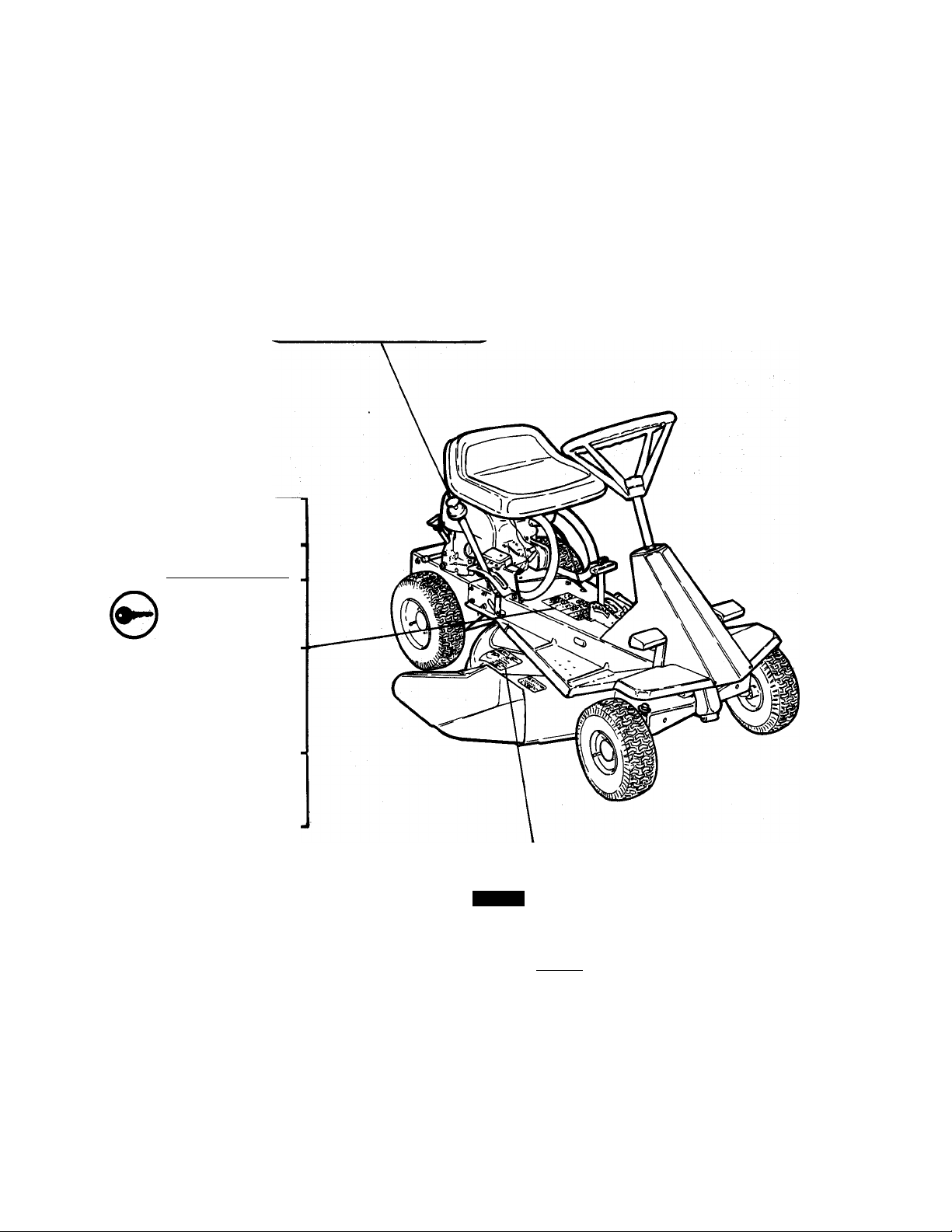
User Service Components
Publications are available for riding mower
owners who wish to perform some of their own
maintenance and service operations. Should a
complete parts and/or repair manual be
desired, use the convenient order form sup
plied with your warranty registration or order
by machine model and serial number.
Lubricate unit according to instructions in
Lubrication and Maintenance Section of this ■
manual.
Clean unit thoroughly. Touch up all painted
areas to avoid rust and store in a cool, dry pro
tected place.
Mail Requests to:
Components illustrated and described in this
manual are most commonly used for consumer
service and can be ordered through your
Ariens Dealer. When ordering parts always in
clude the Model and Serial Number of your unit
to assure prompt service.
Ariens Service
655 West Ryan Street
Brillion, Wl 54110-1098
1. Drive Beit
2. Battery
3. Mower Beit
4. Mower Biade
Figure 17: User Service Components
20
Attachments
812004 Rear Grass Catcher
Accessories
712006
512021
Front Weight
Service Bar Package
Page 23

Ask your dealer for information
about these other fine Ariens
products:
c^riens
Ariens Company
655 W. Ryan Street
Brillion.WI 54110-1098
 Loading...