

Page 1

Wide Area Walk Mower
Owner/Operator Manual
Models
911403 - WAW 1034
911407 - WAW 1034 CARB
__ _ ENGL,SH
01254000C 9/08
Printed in USA
Page 2
/ Y:_:] i _[o]_ _o]_//_/[_
Safety ........................... 4
Assembly ........................ 9
Controls and Features ............ 11
Operation ....................... 12
Maintenance ..................... 15
Service and Adjustments .......... 17
II_/llt_e_o]_l
Storage ......................... 22
Troubleshooting ................. 22
Service Parts .................... 23
Accessories ..................... 23
Specifications ................... 24
Warranty ........................ 25
NON-ENGLISH MANUALS
Manuals in languages other than
English may be obtained from
your Dealer. Visit your dealer or
www.ariens.com for a list of
languages available for your
equipment.
Manuals printed in languages
other than English are also
available as a free download on
our website:
http://www.ariens.com
MANUALES EN IDIOMAS
DIFERENTES DEL INGLES
Puede obtener manuales en
,_ idiomas diferentes del ingles en sudistribuidor. Visite a su distribuidor
o vaya a www.ariens.com para
obtener una lista de idiomas
disponibles para su equipo.
Tambien puede imprimir manuales
en idiomas diferentes del ingles
descargandolos gratuitamente de
nuestra pagina Web:
http://www.ariens.com
MANUELS NON ANGLAIS
Des manuels dans differentes
THE MANUAL
Before using the unit, carefully and
completely read your manuals. The contents
will give you an understanding of safety
instructions and controls during normal
operation and maintenance.
All reference to left, right, front, or rear are
given from the operator's position, facing the
direction of forward travel.
SERVICE AND REPLACEMENT
PARTS
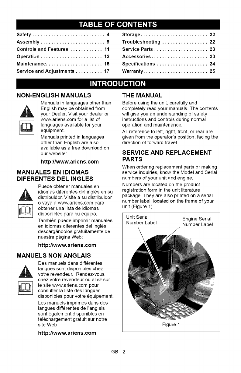
When ordering replacement parts or making
service inquiries, know the Model and Serial
numbers of your unit and engine.
Numbers are located on the product
registration form in the unit literature
package. They are also printed on a serial
number label, located on the frame of your
unit (Figure 1).
Unit Serial Engine Serial
Number Label Number Label
,_ langues sont disponibles chezvotre revendeur. Rendez-vous
chez votre revendeur ou allez sur
le site www.ariens.com pour
consulter la liste des langues
disponibles pour votre equipement.
Les manuels imprimes dans des
langues differentes de I'anglais
sont egalement disponibles en
telechargement gratuit sur notre
site Web :
http://www.ariens.com
Figure 1
GB -2
Page 3
•RecordUnitModelandSerialnumbers
here:
l J
• Record Engine Model & Serial numbers
here:
[ J
PRODUCT REGISTRATION
The Ariens dealer must register the product
at the time of purchase. Registering the
product will help the company process
warranty claims or contact you with the latest
service information. All claims meeting
requirements during the limited warranty
period will be honored, whether or not the
product registration card is returned. Keep a
proof of purchase if you do not register your
unit.
Customer Note: If the Dealer does not
register your product, please fill out, sign and
return the product registration card to Ariens
or go to www.ariens.com on the internet.
UNAUTHORIZED REPLACEMENT
PARTS
Use only Ariens replacement parts.
Replacing any part on this vehicle with
anything other than an Ariens authorized
replacement part may adversely affect the
performance, durability, or safety of this unit
and may void the warranty. Ariens disclaims
liability for any claims or damages, whether
warranty, property damage, personal injury or
death arising out of the use of unauthorized
replacement parts. To locate your nearest
Ariens Dealer, go to www.ariens.com on the
internet.
DEALER DELIVERY
Dealer should:
1. Check that all assembly and
adjustments have been properly
completed.
2. Fill out Original Purchaser Registration
Card and return the card to Ariens.
3. Explain Ariens Limited Warranty Policy.
4. Explain recommended lubrication and
maintenance. Advise customer on
adjustments. Remind customer to
change oil in 4 cycle engine crankcase
after first five (5) hours of operation.
5. Instruct customer on controls and
operation of unit. Discuss and
emphasize the Safety Rules. Give
customer Owner/Operator, Parts, and
Engine manuals. Advise customer to
thoroughly read and understand them.
DISCLAIMER
Ariens reserves the right to discontinue,
make changes to, and add improvements
upon its products at any time without public
notice or obligation.The descriptions and
specifications contained in this manual were
in effect at printing. Equipment described
within this manual may be optional. Some
illustrations may not apply to your unit.
GB-3
Page 4
[,."Y-'1=1=l1"4
WARNING: This cutting machine
is capable of amputating hands
and feet and throwing objects.
Failure to observe the safety
instructions in the manuals and
on decals could result in serious
injury or death.
Slopes are a major factor related
to slip and fall accidents.
Operation on all slopes requires
extra caution.
Tragic accidents can occur if the
operator is not alert to the
presence of children. Never
assume that children will remain
where you last saw them.
Gasoline is extremely flammable
and the vapors are explosive,
handle with care.
Stop unit and engine, remove key
(if equipped) and allow moving
parts to stop before leaving
operator's position.
SAFETY ALERTS
Lookfor these symbols to point
,_ out important safety precautions.
The safety alert symbols above and signal
words below are used on decals and in this
manual.
Read and understand all safety messages.
They mean:
Personal Safety Is Involved!
Attention!
Become Alert!
Obey The Message!
CAUTION: POTENTIALLY
,&
HAZARDOUS SITUATION! If not
avoided, MAY RESULT in minor or
moderate injury. It may also be
used to alert against unsafe
practices.
NOTATIONS
NOTE: General reference information for
proper operation and maintenance practices.
IMPORTANT: Specific procedures or
information required to prevent damage to
unit or attachment.
PRACTICES AND LAWS
Practice usual and customary safe working
precautions, for the benefit of yourself and
others. Understand and follow all safety
messages. Be alert to unsafe conditions and
the possibility of minor, moderate, or serious
injury or death. Learn applicable rules and
laws in your area.
REQUIRED OPERATOR
TRAINING
Original purchaser of this unit was instructed
by the seller on safe and proper operation. If
anyone other than the original purchaser will
use the unit, ALWAYS provide this manual
and any needed safety training before
operation.
DANGER: IMMINENTLY
,_ HAZARDOUS SITUATION! If not
avoided, WILL RESULT in death or
serious injury.
WARNING: POTENTIALLY
HAZARDOUS SITUATION! If not
avoided, COULD RESULT in
death or serious injury.
GB -4
Page 5
SAFETY DECALS AND
LOCATIONS
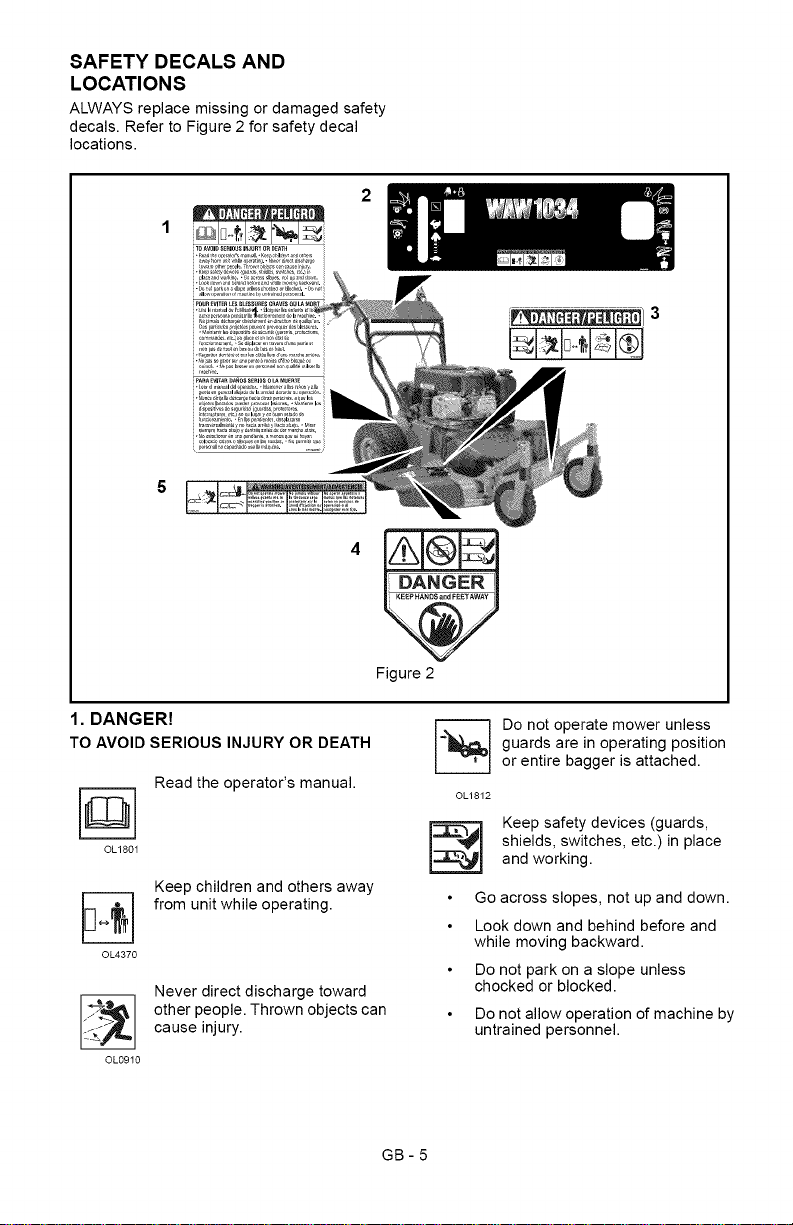
ALWAYS replace missing or damaged safety
decals. Refer to Figure 2 for safety decal
locations.
1
5
1. DANGER!
TO AVOIDSERIOUS INJURYOR DEATH
Read the operator's manual.
OL180I
Keep children and others away
from unit while operating.
©L4370
Never direct discharge toward
other people. Thrown objects can
cause injury.
OL0910
Figure 2
GB-5
guards are in operating position
=] o not operate mower unless
or entire bagger is attached.
©L1812
shields, switches, etc.) in place
Keep safety devices (guards,
and working.
Go across slopes, not up and down.
Look down and behind before and
while moving backward.
Do not park on a slope unless
chocked or blocked.
Do not allow operation of machine by
untrained personnel.
Page 6
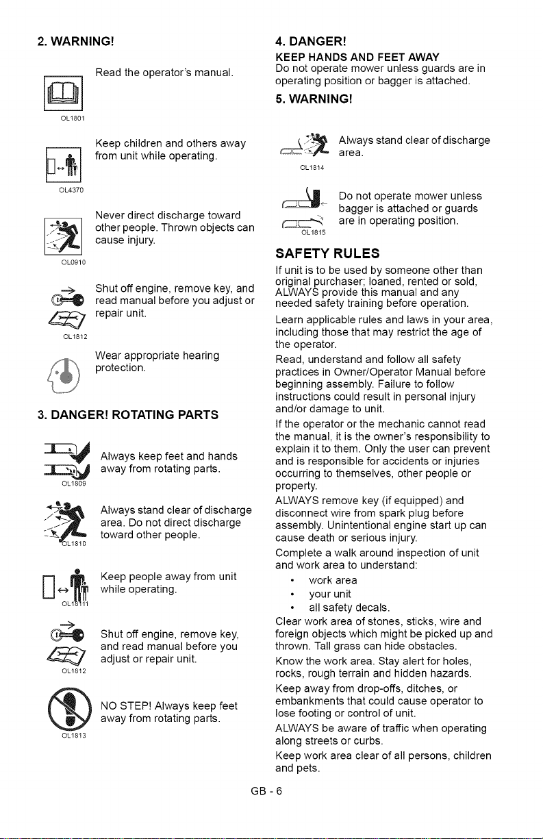
2. WARNING!
OL1801
Read the operator's manual.
4. DANGER!
KEEP HANDS AND FEET AWAY
Do not operate mower unless guards are in
operating position or bagger is attached.
5. WARNING!
Keep children and others away
from unit while operating.
OL4370
Never direct discharge toward
other people. Thrown objects can
cause injury.
OL0910
Shut off engine, remove key, and
read manual before you adjust or
repair unit.
OL1812
Wear appropriate hearing
protection.
3. DANGER! ROTATING PARTS
Always keep feet and hands
away from rotating parts.
OL1809
Always stand clear of discharge
area. Do not direct discharge
toward other people.
Keep people away from unit
while operating.
Shut off engine, remove key,
and read manual before you
adjust or repair unit.
OL1812
@
NO STEP! Always keep feet
away from rotating parts.
OL1813
_ AIwaySarea.stand clearofdischarge
OLt814
÷ Do not operate mower unless
bagger is attached or guards
are in operating position.
OL1815
SAFETY RULES
If unit is to be used by someone other than
original purchaser; loaned, rented or sold,
ALWAYS provide this manual and any
needed safety training before operation.
Learn applicable rules and laws in your area,
including those that may restrict the age of
the operator.
Read, understand and follow all safety
practices in Owner/Operator Manual before
beginning assembly. Failure to follow
instructions could result in personal injury
and/or damage to unit.
If the operator or the mechanic cannot read
the manual, it is the owner's responsibility to
explain it to them. Only the user can prevent
and is responsible for accidents or injuries
occurring to themselves, other people or
property.
ALWAYS remove key (if equipped) and
disconnect wire from spark plug before
assembly. Unintentional engine start up can
cause death or serious injury.
Complete a walk around inspection of unit
and work area to understand:
work area
your unit
all safety decals.
Clear work area of stones, sticks, wire and
foreign objects which might be picked up and
thrown. Tall grass can hide obstacles.
Know the work area. Stay alert for holes,
rocks, rough terrain and hidden hazards.
Keep away from drop-offs, ditches, or
embankments that could cause operator to
lose footing or control of unit.
ALWAYS be aware of traffic when operating
along streets or curbs.
Keep work area clear of all persons, children
and pets.
GB -6
Page 7

Keepchildrenoutoftheworkareaandunder
thewatchfulcareofaresponsibleadult.
ALWAYSoperateunitwhenthereisgood
visibilityandlight.
DONOTmowwetgrass.
ALWAYSbesureofyourfooting.Keepafirm
holdonhandlebar.Walk,NEVERrun.
Engine/bladecontrolfeatureonmowerstops
engineandbladewithin5secondswhenever
operatorreleasesPTOlever.Checkthis
featurefrequently.Iffeaturefailstooperate,
disconnectsparkplugwireandadjustorhave
itrepairedbeforeusingunit.
Onlytrainedadultsmayoperateorservice
unit.Trainingincludesactualoperation.The
ownerisresponsiblefortrainingusers.
NEVERoperateafterorduringtheuseof
medication,drugsoralcohol.Unitrequires
completeandunimpairedattention.
NEVERallowchildrentouseorservice
mower.
ALWAYSkeephandsandfeetawayfrom
rotatingparts.Rotatingpartscancutoffbody
parts.
ALWAYSkeephandsawayfrompinchpoints.
Fumesfromengineexhaustcancausedeath
orseriousinjury.DONOTrunengineinan
enclosedarea.
ALWAYSprotecteyes,face,andbodywith
adequatesafetygearandprotectiveclothes.
Wearsturdyfootwear,gloves,ahardhatand
safetygogglesorsafetyglasseswithside
shieldswhileoperatingmower.
Wearappropriatehearingprotection.
NEVERoperatemowerbarefootorwhen
wearingopensandalsorcanvasshoes.
NEVERwearlooseclothes,longhairor
jewelrythatmaygetcaughtinrotatingparts.
ALWAYSstandclearofdischargewhen
operatingunit.
NEVERdirectdischargetowardbystanders.
Operatorisresponsibleforbystandersafety.
DONOTtouchhotparts.Allowpartstocool.
Keepsafetydevicesorguardsinplaceand
functioningproperly.NEVERmodifyor
removesafetydevices.
Read,understand,andfollowallinstructions
inthemanualandonthemachinebefore
starting.Understand:
Howtooperateallcontrols
Thefunctionsofallcontrols
HowtoSTOPinanemergency.
DONOTattempttostartyourengineuntil
youknowwhatthecontrolsdoandhowthey
work.
GB-7
DONOTtiltmowerwhenstartingit.
Keepfeetawaywhenstartingengine.
DONOTstarttheengineoroperatemower
withoutsidedischargecoverorside
dischargedeflectorinstalled.
Neverleavearunningunitunattended.
Takeallpossibleprecautionswhenleaving
unitunattended.
ALWAYSshutoffengine,removekey
(electricstartmodels)anddisconnectspark
plugwiretopreventaccidentalstartingor
unauthorizeduse.
Stopengineifanyoneenterstheworkarea.
NEVERattempttomakeanyadjustmentsto
unitwhileengineisrunning(exceptwhere
specificallyrecommended).Stopengine,
removekey(electricstartmodels)andwait
forallmovingpartstostopbeforeservicing.
DONOTmakecuttingheightwheel
adjustmentswhiletheengineisrunning.
Ifyoustrikeanobject,orifequipment
vibratesabnormally,stopengineatonce,wait
formovingpartstostopanddisconnectwire
fromsparkplug.Repairanydamagebefore
restartingunit.
Stopenginebeforeremovingandemptying
grassbag.
Whenmulchingorbagging,ALWAYSinstall
dischargecover.
Whensidedischarging,ALWAYSinstallside
dischargedeflector.
ALWAYSshutoffengine,allowbladetostop
anddisconnectsparkplugwirebefore
clearingclogsorcleaningunit.
Checkgrassbagforwear,damage,and/or
deterioration.ReplaceonlywithAriens
originalequipmentreplacementpartsfor
safety.
Toreducefirehazardandoverheating,keep
equipmentfreeofgrass,leaves,debrisor
excessivelubricants.
Useextracarewhenapproachingblind
corners,shrubs,trees,orotherobjectswhich
mayobscurevision.
DONOTmowattoofastarate.DONOT
changeenginegovernorsettingorover-
speedtheengine.
Donotoperatemowerongravelorloose
materialsuchassand.Stopmowerwhen
crossingdrives,walks,orroadstoprevent
damageorinjuryfromthrownobjects.
DONOTpullmowerbackwardsunless
absolutelynecessary.Lookdownandback,
especiallyforsmallchildren,beforeandwhile
movingbackwards.
Page 8
Onself-propelledmodels,releasingwheel
drivecontrolmuststopmower'sforward
movement.Ifthisfeaturefailstooperate,
disconnectsparkplugwireandrepairbefore
usingunit.
Onself-propelledmodels,wheeldrivemust
bedisengagedwhenstartingengine.
DONOToperateonsteepslopes.
NEVERleaveunitunattendedonaslope.
Chockwheelsifparkingonaslope.
Mowacrossthefaceofslopes,neverupand
down.Beespeciallycautiouswhenchanging
directiononslopes.
Thisproductisequippedwithaninternal
combustionengine.DONOTuseonornear
anyunimproved,forestorbrushcoveredland
unlesstheexhaustsystemisequippedwitha
sparkarrestormeetingapplicablelocal,state
orfederallaws.Asparkarrestor,ifused,
mustbemaintainedineffectiveworkingorder
bytheoperator.SeeyourAriensDealeror
enginemanufacturer'sservicecenter.
Emission Control System
Certification Label
NOTE: Tampering with emission controls and
components by unauthorized personnel may
result in severe fines or penalties. Emission
controls and components can only be
adjusted by EPA and/or CARB authorized
service centers.Contact your Ariens
Equipment Retailer concerning emission
controls and component questions.
Fuel is highly flammable and its vapors can
explode. ONLY use approved fuel containers.
NO Smoking!
NO Sparks!
NO Flames!
Allow engine to cool before filling fuel
tank.
Never fill containers inside a vehicle or on a
truck or trailer bed with a plastic liner. Always
place containers on the ground away from
your vehicle before filling.
When practical, remove gas-powered
equipment from the truck or trailer and refuel
it on the ground. If this is not possible, then
refuel such equipment on a trailer with a
portable container, rather than from a
gasoline dispenser nozzle.
Keep the nozzle in contact with the rim of the
fuel tank or container opening at all times until
fueling is complete. Do not use a nozzle lock-
open device.
Check fuel supply before starting engine.
DO NOT fill gasoline tank indoors, when
engine is running, or while engine is hot.
Allow engine to cool several minutes before
removing fuel cap.
DO NOT overfill. Allow about 1/4" (6 mm) of
tank space for fuel expansion.
Replace gasoline tank cap securely and
clean any spilled fuel before starting engine.
If fuel is spilled on clothing, change clothing
immediately.
NEVER store fuel inside where there is an
open flame, such as a water heater.
ALWAYS drain fuel outdoors away from
ignition sources.
ALWAYS shut off and remove key, engine
when transporting unit on a truck or trailer.
Avoid Electric Shock. DO NOT disconnect
wire from spark plug while engine is running.
Do NOT put battery in fire or mutilate.
Explosive Gases!
NO flames, NO sparks, NO smoking, near
battery.
Poisonous battery fluid contains sulfuric acid.
Contact with skin, eyes or clothing can cause
severe chemical burns.
ALWAYS wear safety glasses and protective
gear near battery.
ALWAYS keep batteries out of reach of
children.
Battery posts, terminals and related
accessories contain lead and lead
compounds, chemicals known to the State of
California to cause cancer and reproductive
harm. Wash hands after handling.
Charge batteries in an open, well-ventilated
area, away from spark and flames. Unplug
charger before connecting or disconnecting
battery. Wear protective clothing and use
insulated tools.
Accidental engine start up can cause death or
serious injury. Except where specifically
recommended, ALWAYS stop engine,
remove key (electric start models), wait for
moving parts to stop, allow parts to cool and
disconnect spark plug wire before inspecting,
servicing, adjusting or repairing unit.
Keep mower free of grass, leaves, or other
debris build-up.
Keep equipment in good condition.
Maintain or replace safety and instruction
labels, as necessary.
Follow engine manufacturer's safety
instruction when servicing engine.
Check all hardware at regular intervals,
especially blade attachment bolts. Keep all
hardware properly tightened.
GB -8
Page 9
Anextensionspring,whenextended,stores
energyandcanbedangerous.Alwaysuse
toolsspecificallydesignedforinstallingor
removinganextensionspring.Always
compressorextendspringsslowly.
Beforetippingunit,removefuelandbattery(if
equipped).
Useextracarewhenloadingorunloading
unitontotrailerortruck.
Ensureallwheelblocks,jackstandsandtie
downswillsupportunitduringmaintenance.
Replaceworn-outmufflersimmediately.
Continuedusecouldresultinfireor
explosion.
Sharpedgescancutoramputatefingersora
hand.Wrapbladeorwearsturdyglovesto
service.
Onlyreplaceblades.NEVERstraightenor
weld blades.
7_,_,.."_"]=1_N-']_'d
CAUTION: AVOID INJURY. Read
_k and understand the entire Safety
section before proceeding.
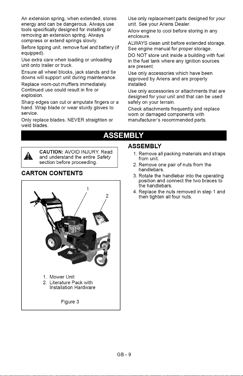
CARTON CONTENTS
1
2
Use only replacement parts designed for your
unit. See your Ariens Dealer.
Allow engine to cool before storing in any
enclosure.
ALWAYS clean unit before extended storage.
See engine manual for proper storage.
DO NOT store unit inside a building with fuel
in the fuel tank where any ignition sources
are present.
Use only accessories which have been
approved by Ariens and are properly
installed.
Use only accessories or attachments that are
designed for your unit and that can be used
safely on your terrain.
Check attachments frequently and replace
worn or damaged components with
manufacturer's recommended parts.
ASSEMBLY
1. Remove all packing materials and straps
from unit.
2. Remove one pair of nuts from the
handlebars.
3. Rotate the handlebar into the operating
position and connect the two braces to
the handlebars.
4. Replace the nuts removed in step 1 and
then tighten all four nuts.
1. Mower Unit
2. Literature Pack with
Installation Hardware
Figure 3
GB-9
Page 10
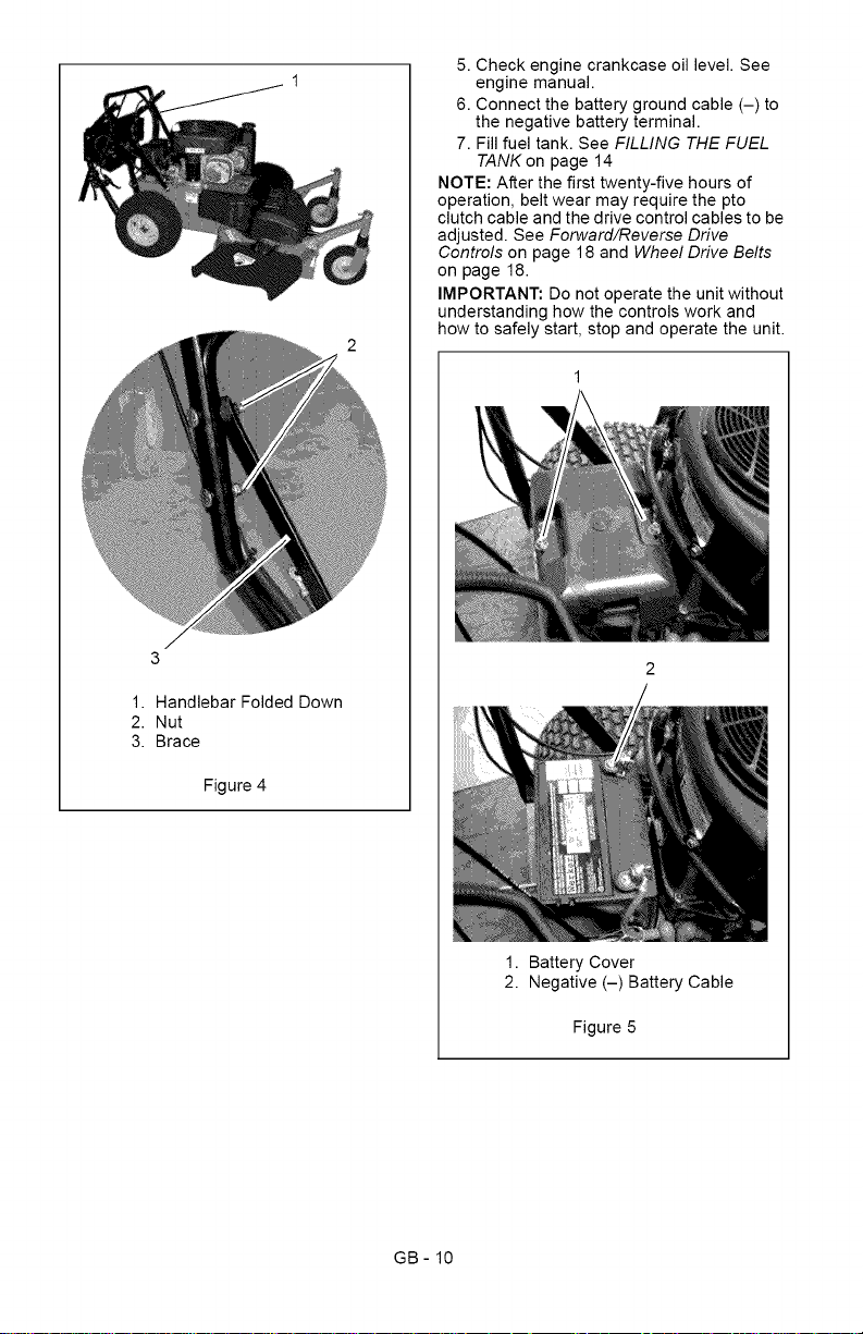
5.Checkenginecrankcaseoillevel.See
enginemanual.
6.Connectthebatterygroundcable(-)to
thenegativebatteryterminal.
7.Fillfueltank.SeeFILLING THE FUEL
TANKon page 14
NOTE: After the first twenty-five hours of
operation, belt wear may require the pto
clutch cable and the drive control cables to be
adjusted. See Forward/Reverse Drive
Controls on page 18 and Wheel Drive Belts
on page 18.
IMPORTANT: Do not operate the unit without
understanding how the controls work and
how to safely start, stop and operate the unit.
1.HandlebarFoldedDown
2.Nut
3.Brace
Figure4
1. Battery Cover
2. Negative (-) Battery Cable
Figure 5
GB- 10
Page 11
1
2
4 /
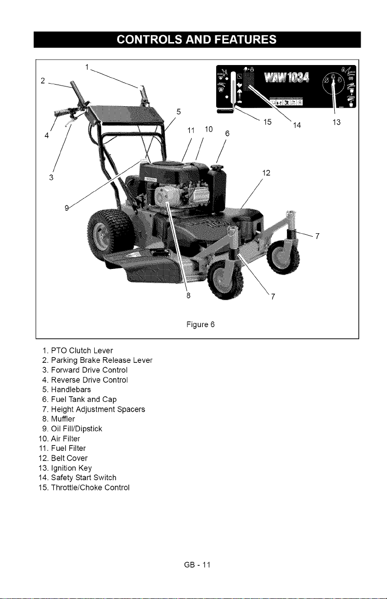
1. PTO Clutch Lever
2. Parking Brake Release Lever
3. Forward Drive Control
4. Reverse Drive Control
5. Handlebars
6. Fuel Tank and Cap
7. Height Adjustment Spacers
8. Muffler
9. Oil Fill/Dipstick
10. Air Filter
11. Fuel Filter
12. Belt Cover
13. Ignition Key
14. Safety Start Switch
15. Throttle/Choke Control
5
10
11
Figure 6
/
6
14
12
13
GB- 11
Page 12
[e]'-]:I_,_:_Ii[e]_I
CONTROLS AND FEATURES
See Figure 6 for locations.
WARNING: Improper operation
A can lead to injury. Learn what the
controls do and how they work.
Thoroughly read and understand
entire Operator Manual.
CAUTION: AVOID INJURY. Read
A and understand the entire Safety
section before proceeding.
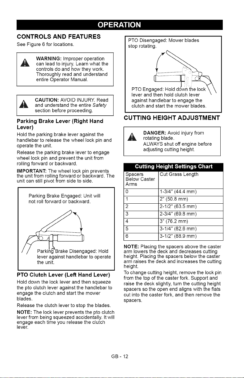
Parking Brake Lever (Right Hand
Lever)
Hold the parking brake lever against the
handlebar to release the wheel lock pin and
operate the unit.
Release the parking brake lever to engage
wheel lock pin and prevent the unit from
rolling forward or backward.
IMPORTANT: The wheel lock pin prevents
the unit from rolling forward or backward. The
unit can still pivot from side to side.
Parking Brake Engaged: Unit will
not roll forward or backward.
'_Brake Disengaged: Hold
lever against handlebar to operate
the unit.
PTO Clutch Lever (Left Hand Lever)
Hold down the lock lever and then squeeze
the pto clutch lever against the handlebar to
engage the clutch and start the mower
blades.
Release the clutch lever to stop the blades.
NOTE: The lock lever prevents the pto clutch
lever from being squeezed accidentally. It will
engage each time you release the clutch
lever.
PTO Disengaged: Mower blades
stop rotating.
PTO Engaged: Hold
lever and then hold clutch lever
against handlebar to engage the
clutch and start the mower blades.
CUTTING HEIGHT ADJUSTMENT
DANGER: Avoid injury from
A rotating blade.
ALWAYS shut off engine before
adjusting cutting height.
[.._4j ,_ [o,,]_"1_"1'_|
Spacers Cut Grass Length
Below Caster
Arms
0 1-3/4" (44.4 mm)
1 2" (50.8 mm)
2 2-1/2" (63.5 mm)
3 2-3/4" (69.8 mm)
4 3" (76.2 mm)
5 3-1/4" (82.6 mm)
6 3-1/2" (88.9 mm)
NOTE: Placing the spacers above the caster
arm lowers the deck and decreases cutting
height. Placing the spacers below the caster
arm raises the deck and increases the cutting
height.
To change cutting height, remove the lock pin
from the top of the caster fork. Support and
raise the deck slightly, turn the cutting height
spacers so the open end aligns with the flats
cut into the caster fork, and then remove the
spacers.
GB- 12
Page 13
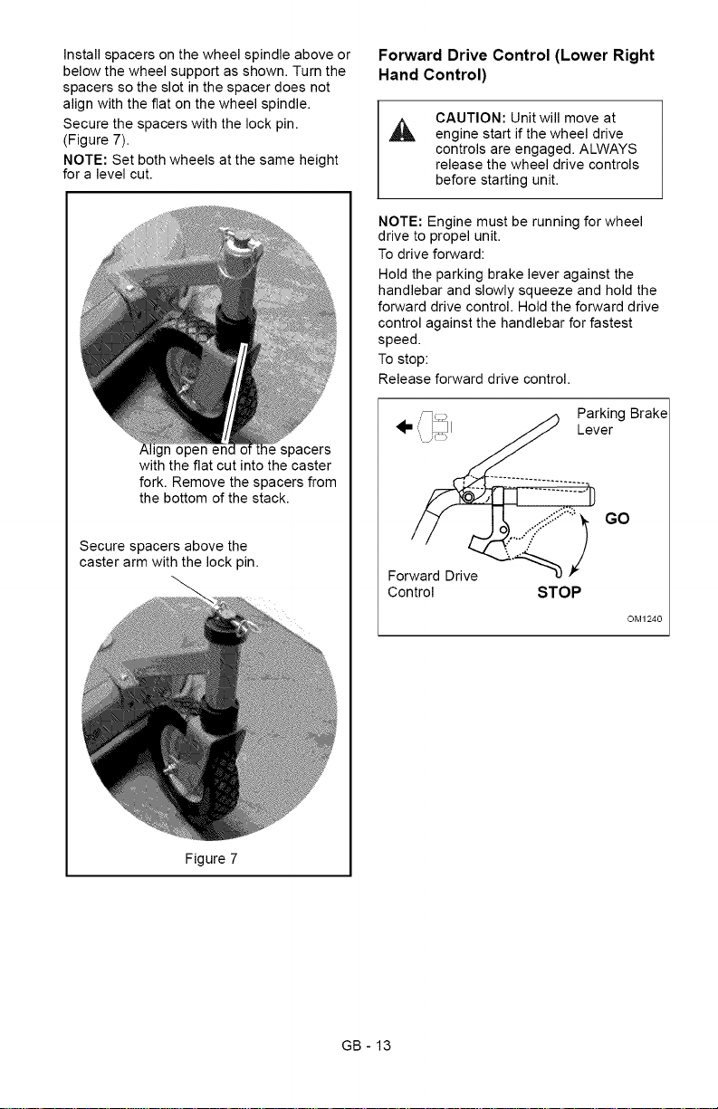
Installspacersonthewheelspindleaboveor
belowthewheelsupportasshown.Turnthe
spacerssotheslotinthespacerdoesnot
alignwiththeflatonthewheelspindle.
Securethespacerswiththelockpin.
(Figure7).
NOTE:Setbothwheelsatthesameheight
foralevelcut.
ignopenenc lespacers
withtheflatcutintothecaster
fork.Removethespacersfrom
thebottomofthestack.
Securespacersabovethe
casterarmwiththelockpin.
Forward Drive Control (Lower Right
Hand Control)
CAUTION: Unit will move at
A
engine start if the wheel drive
controls are engaged. ALWAYS
release the wheel drive controls
before starting unit.
NOTE: Engine must be running for wheel
drive to propel unit.
To drive forward:
Hold the parking brake lever against the
handlebar and slowly squeeze and hold the
forward drive control. Hold the forward drive
control against the handlebar for fastest
speed.
To stop:
Release forward drive control.
Parking Brake
Lever
GO
Forward Drive
Control
STOP
OM1240
Figure7
GB - 13
Page 14
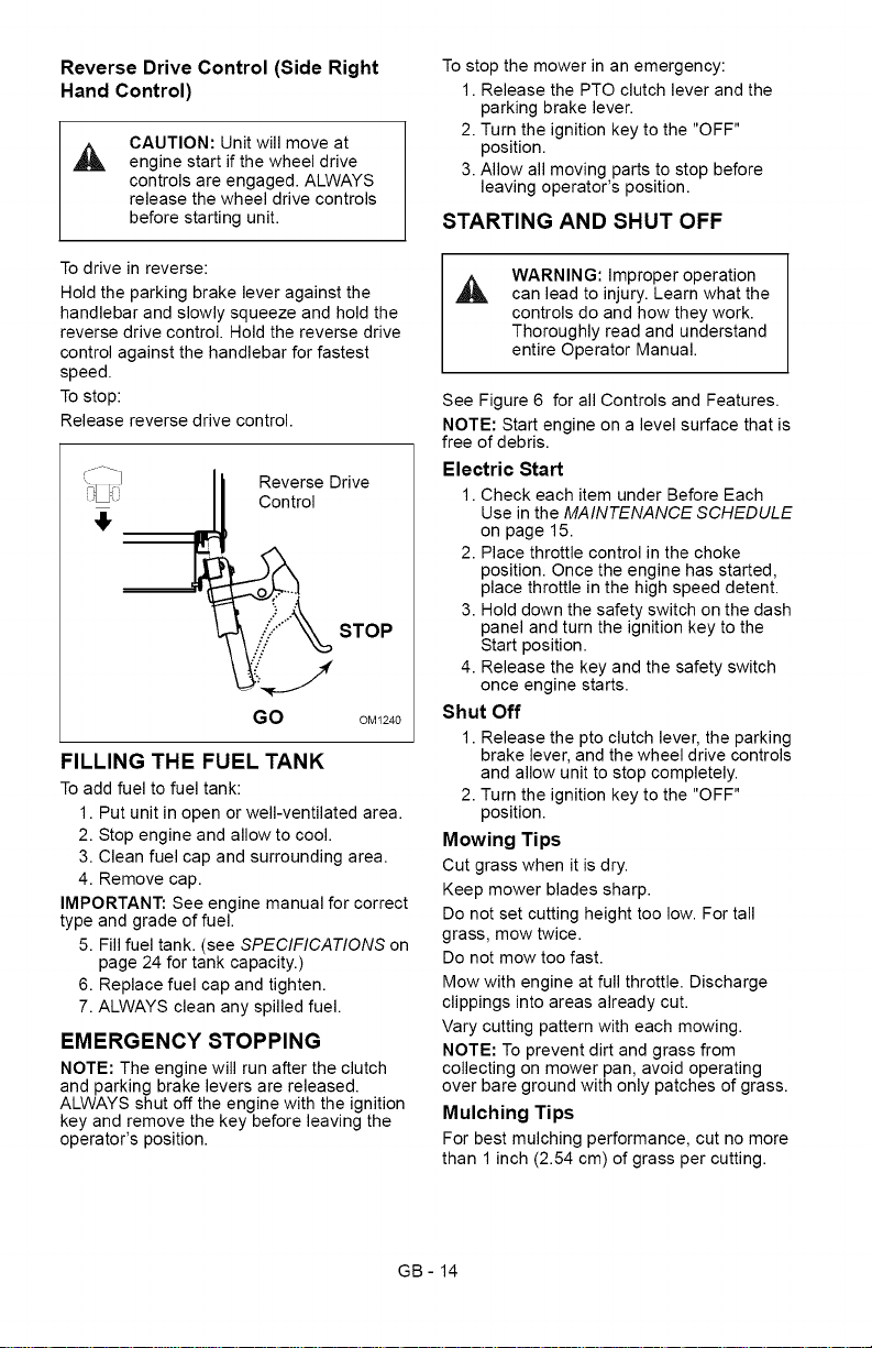
Reverse Drive Control (Side Right
Hand Control)
CAUTION: Unit will move at
engine start if the wheel drive
controls are engaged. ALWAYS
release the wheel drive controls
before starting unit.
To stop the mower in an emergency:
1. Release the PTO clutch lever and the
parking brake lever.
2. Turn the ignition key to the "OFF"
position.
3. Allow all moving parts to stop before
leaving operator's position.
STARTING AND SHUT OFF
To drive in reverse:
Hold the parking brake lever against the
handlebar and slowly squeeze and hold the
reverse drive control. Hold the reverse drive
control against the handlebar for fastest
speed.
To stop:
Release reverse drive control.
Reverse Drive
,!, rol
_"_ STOP
"_O'_ OM1240
FILLING THE FUEL TANK
To add fuel to fuel tank:
1. Put unit in open or well-ventilated area.
2. Stop engine and allow to cool.
3. Clean fuel cap and surrounding area.
4. Remove cap.
IMPORTANT: See engine manual for correct
type and grade of fuel.
5. Fill fuel tank. (see SPECIFICATIONS on
page 24 for tank capacity.)
6. Replace fuel cap and tighten.
7. ALWAYS clean any spilled fuel.
EMERGENCY STOPPING
NOTE: The engine will run after the clutch
and parking brake levers are released.
ALWAYS shut off the engine with the ignition
key and remove the key before leaving the
operator's position.
WARNING: Improper operation
can lead to injury. Learn what the
controls do and how they work.
Thoroughly read and understand
entire Operator Manual.
See Figure 6 for all Controls and Features.
NOTE: Start engine on a level surface that is
free of debris.
Electric Start
1. Check each item under Before Each
Use in the MAINTENANCE SCHEDULE
on page 15.
2. Place throttle control in the choke
position. Once the engine has started,
place throttle in the high speed detent.
3. Hold down the safety switch on the dash
panel and turn the ignition key to the
Start position.
4. Release the key and the safety switch
once engine starts.
Shut Off
1. Release the pto clutch lever, the parking
brake lever, and the wheel drive controls
and allow unit to stop completely.
2. Turn the ignition key to the "OFF"
position.
Mowing Tips
Cut grass when it is dry.
Keep mower blades sharp.
Do not set cutting height too low. For tall
grass, mow twice.
Do not mow too fast.
Mow with engine at full throttle. Discharge
clippings into areas already cut.
Vary cutting pattern with each mowing.
NOTE: To prevent dirt and grass from
collecting on mower pan, avoid operating
over bare ground with only patches of grass.
Mulching Tips
For best mulching performance, cut no more
than 1 inch (2.54 cm) of grass per cutting.
GB- 14
Page 15
,_ CAUTION: AVOID INJURY. Read
and understand the entire Safety
section before proceeding.
Ariens Dealers will provide any service, parts
or adjustments which may be required to
keep your unit operating at peak efficiency.
Should engine require service, contact an
Ariens Dealer or an authorized engine
manufacturer's service center.
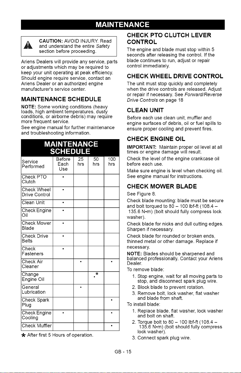
MAINTENANCE SCHEDULE
NOTE: Some working conditions (heavy
loads, high ambient temperatures, dusty
conditions, or airborne debris) may require
more frequent service.
See engine manual for further maintenance
and troubleshooting information.
Service
Performed
Check PTO
Clutch
Check Wheel
Drive Control
Clean Unit
Check Engine
Oil
Check Mower
Blade
Check Drive
Belts
Check
Fasteners
Check Air
Cleaner
Change
Engine Oil
General
Lubrication
Check Spark
Plug
Check Engine
Cooling
Check Muffler
After first 5 Hours of operation.
CHECK PTO CLUTCH LEVER
CONTROL
The engine and blade must stop within 5
seconds after releasing the control. If the
blade continues to run, adjust or repair
control immediately.
CHECK WHEEL DRIVE CONTROL
The unit must stop quickly and completely
when the drive controls are released. Adjust
or repair if necessary. See Forward/Reverse
Drive Controls on page 18
CLEAN UNIT
Before each use clean unit, muffler and
engine surfaces of debris, oil or fuel spills to
ensure proper cooling and prevent fires.
CHECK ENGINE OIL
IMPORTANT: Maintain proper oil level at all
times or engine damage will result.
Check the level of the engine crankcase oil
before each use.
Make sure engine is level when checking oil.
See engine manual for instructions.
CHECK MOWER BLADE
See Figure 8.
Check blade mounting: blade must be secure
and bolt torqued to 80 - 100 Ibf-ft (108.4 -
135.6 N°m) (bolt should fully compress lock
washer).
Check blade for nicks and dull cutting edges.
Sharpen if necessary.
Check blade for rounded or broken ends,
thinned metal or other damage. Replace if
necessary.
NOTE: Blades should be sharpened and
balanced professionally. Contact your Ariens
Dealer.
To remove blade:
1. Stop engine, wait for all moving parts to
stop, and disconnect spark plug wire.
2. Block blade to prevent rotation.
3. Remove bolt, lock washer, flat washer
and blade from shaft.
To install blade:
1. Replace blade, flat washer, lock washer
and bolt on shaft.
2. Torque bolt to 80- 100 Ibf-ft (108.4-
135.6 N°m) (bolt should fully compress
lock washer).
3. Connect spark plug wire.
GB- 15
Page 16
Sharpen the Mower Blades
CAUTION: DO NOT sharpen
mower blades while on unit. An
imbalanced mower blade will
cause excessive vibration and
eventual damage to unit. Check
mower blade balance before
reinstalling blades.
NEVER weld or straighten bent
blades.
1. Remove mower blade from unit.
Discard mower blade if:
More than 1/2 in. (1.27 cm) of metal is
removed.
Air lifts become eroded.
Blade is bent or broken.
2. Sharpen mower blade by removing an
equal amount of material from each end
of mower blade. DO NOT change angle
of cutting edge or round the corner of the
mower blade.
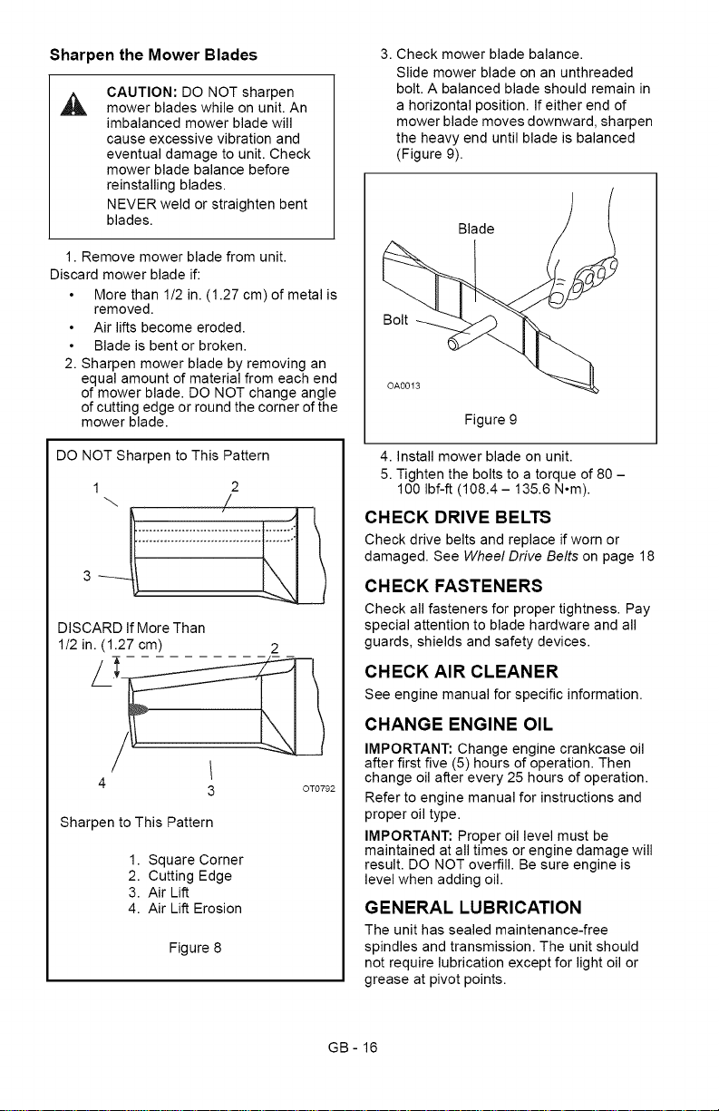
3. Check mower blade balance.
Slide mower blade on an unthreaded
bolt. A balanced blade should remain in
a horizontal position. If either end of
mower blade moves downward, sharpen
the heavy end until blade is balanced
(Figure 9).
Blade
Bolt
Figure 9
DO NOT Sharpen to This Pattern
1 2
DISCARD If More Than
1/2 in. (1.27 cm) 2
4
Sharpen to This Pattern
1. Square Corner
2. Cutting Edge
3. Air Lift
4. Air Lift Erosion
3 OT0792
Figure 8
4. Install mower blade on unit.
5. Tighten the bolts to a torque of 80 -
100 Ibf-ft (108.4 - 135.6 N°m).
CHECK DRIVE BELTS
Check drive belts and replace if worn or
damaged. See Wheel Drive Belts on page 18
CHECK FASTENERS
Check all fasteners for proper tightness. Pay
special attention to blade hardware and all
guards, shields and safety devices.
CHECK AIR CLEANER
See engine manual for specific information.
CHANGE ENGINE OIL
IMPORTANT: Change engine crankcase oil
after first five (5) hours of operation. Then
change oil after every 25 hours of operation.
Refer to engine manual for instructions and
proper oil type.
IMPORTANT: Proper oil level must be
maintained at all times or engine damage will
result. DO NOT overfill. Be sure engine is
level when adding oil.
GENERAL LUBRICATION
The unit has sealed maintenance-free
spindles and transmission. The unit should
not require lubrication except for light oil or
grease at pivot points.
GB- 16
Page 17
CHECK SPARK PLUG
Spark plug should be replaced every 100
hours of operation or each year.
NOTE: Loose spark plug wire terminals can
cause sparking. Replace terminal if
damaged.
CHECK ENGINE COOLING
WARNING: HOT SURFACES can
,&
cause death or serious injury. DO
NOT TOUCH parts which are hot
from operation. ALWAYS allow
parts to cool.
To prevent overheating, air must circulate
freely around the cooling fins, cylinder head
and block.
Every 100 hours of operation or yearly (more
often if conditions require) remove blower
housing and clean cooling fins. See engine
manual for instructions.
[,,_o]=l V_4_I m]V_4m_'_l / _v_I=1_II_"]
CAUTION: AVOID INJURY. Read
and understand the entire Safety
section before proceeding.
PTO CLUTCH
CHECK MUFFLER
Check muffler for debris, cracks, wear, or
other damage.
CAUTION: Replace worn-out
mufflers immediately. Continued
use could result in fire or
explosion.
WARNING: If you cannot adjust
the controls so the unit drives
properly, immediately take the unit
to your local authorized dealer for
repairs.
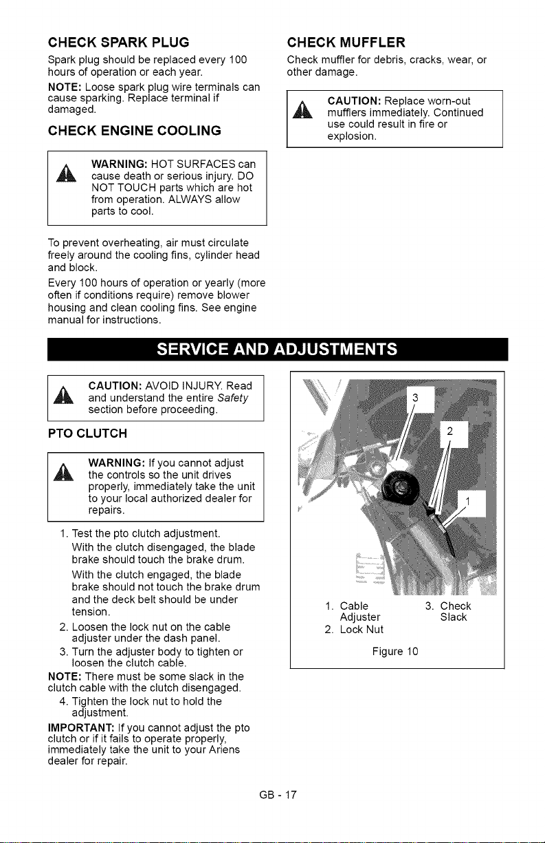
1. Test the pto clutch adjustment.
With the clutch disengaged, the blade
brake should touch the brake drum.
With the clutch engaged, the blade
brake should not touch the brake drum
and the deck belt should be under
tension.
2. Loosen the lock nut on the cable
adjuster under the dash panel.
3. Turn the adjuster body to tighten or
loosen the clutch cable.
NOTE: There must be some slack in the
clutch cable with the clutch disengaged.
4. Tighten the lock nut to hold the
adjustment.
IMPORTANT: If you cannot adjust the pto
clutch or if it fails to operate properly,
immediately take the unit to your Ariens
dealer for repair.
1. Cable 3. Check
Adjuster Slack
2. Lock Nut
Figure 10
GB - 17
Page 18
Forward/Reverse Drive Controls BELT REPLACEMENT
WARNING: If you cannot adjust
the controls so the unit drives
properly, immediately take the unit
to your local authorized dealer for
repairs.
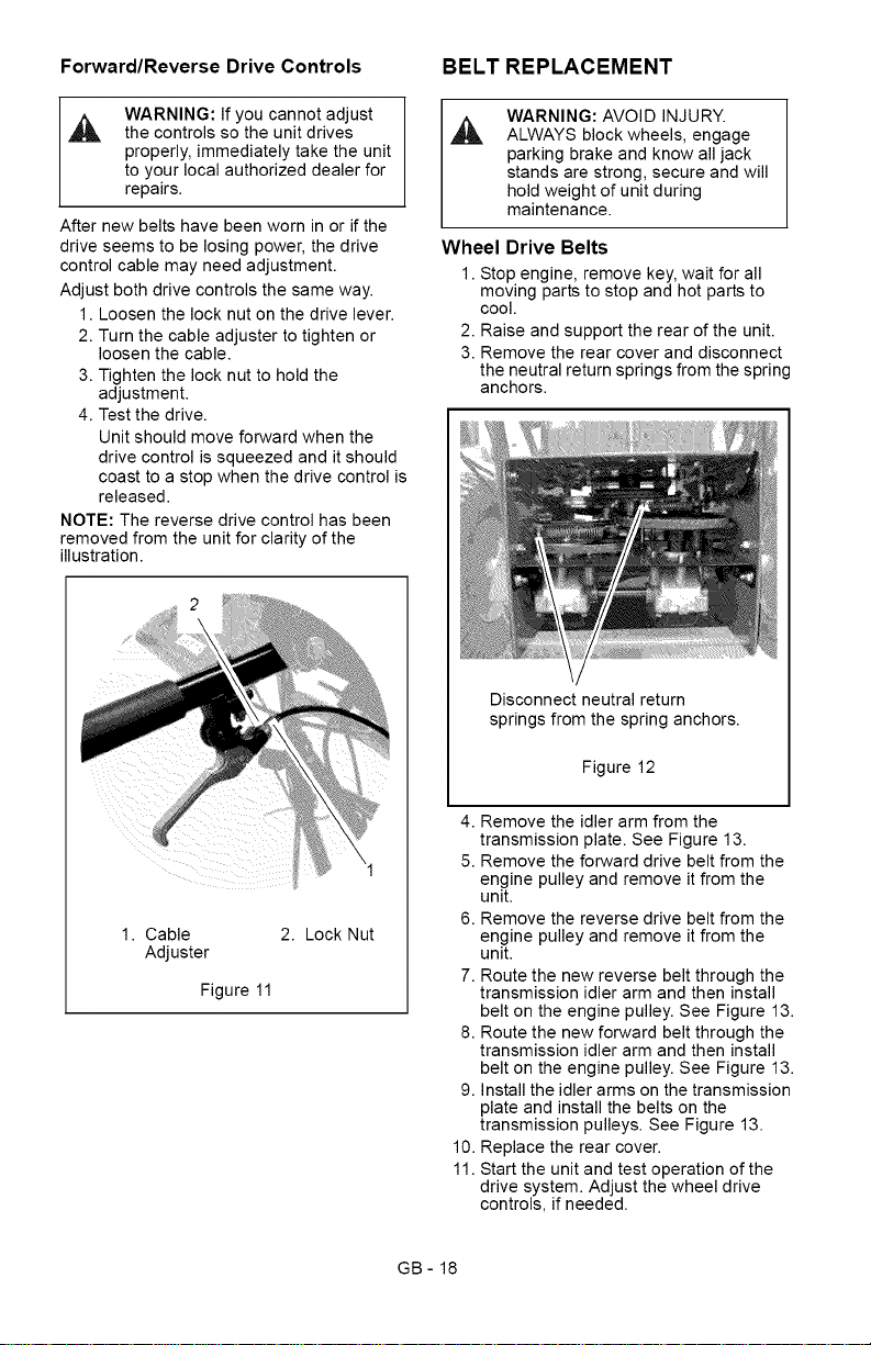
After new belts have been worn in or if the
drive seems to be losing power, the drive
control cable may need adjustment.
Adjust both drive controls the same way.
1. Loosen the lock nut on the drive lever.
2. Turn the cable adjuster to tighten or
loosen the cable.
3. Tighten the lock nut to hold the
adjustment.
4. Test the drive.
Unit should move forward when the
drive control is squeezed and it should
coast to a stop when the drive control is
released.
NOTE: The reverse drive control has been
removed from the unit for clarity of the
illustration.
WARNING: AVOID INJURY.
ALWAYS block wheels, engage
parking brake and know all jack
stands are strong, secure and will
hold weight of unit during
maintenance.
Wheel Drive Belts
1. Stop engine, remove key, wait for all
moving parts to stop and hot parts to
cool.
2. Raise and support the rear of the unit.
3. Remove the rear cover and disconnect
the neutral return springs from the spring
anchors.
Disconnect neutral return
springs from the spring anchors.
1. Cable 2. Lock Nut
Adjuster
Figure 11
Figure 12
4. Remove the idler arm from the
transmission plate. See Figure 13.
5. Remove the forward drive belt from the
engine pulley and remove it from the
unit.
6. Remove the reverse drive belt from the
engine pulley and remove it from the
unit.
7. Route the new reverse belt through the
transmission idler arm and then install
belt on the engine pulley. See Figure 13.
8. Route the new forward belt through the
transmission idler arm and then install
belt on the engine pulley. See Figure 13.
9. Install the idler arms on the transmission
plate and install the belts on the
transmission pulleys. See Figure 13.
10. Replace the rear cover.
11. Start the unit and test operation of the
drive system. Adjust the wheel drive
controls, if needed.
GB- 18
Page 19

NOTE:Checkthewheeldrivecontrol
adjustmentafterthefirst25hoursofuseto
compensateforbeltwear.
RearofUnit-ForwardDriveBeltRouting
I 4
/ I
//
Rear of Unit - Reverse Drive Belt Routing
PTO Belt
1. Stop engine, remove key, wait for all
moving parts to stop and hot parts to
cool.
2. Remove the two drive belts from engine
pulley. See Wheel Drive Belts on
page 18.
3. Remove the belt cover from the deck.
4. Disconnect the two idler springs from the
spring anchors.
NOTE: Do not remove the bolt holding the
engine pulley to the crankshaft. Loosen it
enough so the pto belt clears the belt finger.
5. Loosen the bolt holding the engine
pulley to the crankshaft and slide the
pulley down until the pto belt can be
removed from the pulley.
6. Install the new belt on the engine pulley
and on the deck pulleys.
7. Push the engine pulley up the crankshaft
and tighten the mounting bolt to 55 Ibf-ft
(74.5 N,m).
8. Connect the two idler springs to spring
anchors.
9. Replace the belt cover.
10. Replace the wheel two drive belts on the
engine pulley.
Rear of Unit
3
1. Engine
Pulley
2. Idler Arm
Figure 13
3. Reverse
Drive Belt
4. Forward
Drive Belt
GB - 19
1. PTO Belt
2. Engine Pulley
3. Idler Arm
4. Tension
Spring
5. Spring Anchor
6. Deck Belt
Figure 14
Page 20

Deck Belt
1. Stop engine, remove key, wait for all
moving parts to stop and hot parts to
cool.
2. Remove the two drive belts from engine
pulley. See Wheel Drive Belts on
page 18.
3. Remove the pto belt from the pto clutch.
See PTO Belt on page 19.
4. Remove the two idler arms from the
deck.
5. Remove the deck belt and install the
new belt.
6. Replace the two idler arms on the deck.
7. Replace the pto belt on the pto clutch.
REPLACING MOWER BLADE
Remove (Figure 15)
CAUTION: Mower blades are
sharp and can cut you. Wrap the
blades or wear gloves, and use
extra caution when servicing
them.
1. Block mower blades to prevent rotation.
2. Remove mounting hardware and mower
blades from mower deck.
Install (Figure 15)
1. Install mower blades on mower deck
with mounting hardware.
2. Torque 5/8-inch hex bolt to 80 -
100 Ibf-ft (108.4 - 135.6 N°m).
1. Flat Washer
2. Bevel
Washer
Figure 15
3. 5/8-inch
Hex Bolt
4. Mower
Blade
SERVICING THE BATTERY
NOTE: Unit comes equipped with a
maintenance-free battery that requires no
regular maintenance except cleaning the
terminals.
WARNING: Battery posts,
,&
terminals and related accessories
contain lead and lead
compounds, chemicals known to
the State of California to cause
cancer and reproductive harm.
Wash hands after handling.
Battery Removal and Installation
Remove (Figure 16)
1. Remove the battery cover.
2. Disconnect negative (-) cable first, then
positive (+) cable.
3. Remove battery from unit.
Install (Figure 16)
1. Install battery on the unit.
2. Connect positive (+) cable first, then
negative (-) cable.
3. Apply petroleum jelly or dielectric grease
to battery cable ends and terminals.
4. Replace the battery cover.
GB - 20
Page 21

3 2
4
5
1.BatteryCover
2.Negative(-)
Cable
3.Negative(-)
Terminal
4.Battery
5.Positive(+)
Terminal
6.Positive(+)
cable
Figure16
Cleaning Battery and Battery Cables
(Figure 16)
1. Remove the battery cover.
2. Disconnect negative (-) cable first, then
positive (+) cable.
3. Clean battery cable ends, negative (-)
terminal, and positive (+) terminal with a
wire brush and rinse with a weak baking
soda solution.
4. Connect positive (+) cable first, then
negative (-) cable.
5. Apply petroleum jelly or dielectric grease
to battery cable ends and terminals.
6. Replace belt cover.
Charging the Battery
WARNING: FROZEN
BATTERIES CAN EXPLODE
and result in death or serious
injury. DO NOT charge a frozen
battery. Let the battery thaw
before charging.
Follow First Aid directions for contact with
battery fluid.
External Contact: Flush with water.
Eyes: Flush with water for at least 15
minutes and get medical attention
immediately!
Internal Contact: Drink large quantities
of water. Follow with Milk of Magnesia,
beaten egg or vegetable oil. Get
medical attention immediately!
In case of internal contact, DO NOT
induce vomiting!
IMPORTANT: DO NOT fast charge. Charging
at a higher rate will damage or destroy
battery.
IMPORTANT: ALWAYS follow information
provided on battery and battery charger.
Contact battery and battery charger
manufacturers' for detailed instructions.
1. Remove battery from unit (see Battery
Removal and Installation on page 20).
2. Place battery in a well-ventilated area.
3. Connect positive (+) lead of charger to
positive (+) _rminal, and negative (-)
lead of charger to negative (-) terminal.
4. Charge battery according to battery
charger and battery manufacturers'
instructions.
5. Install battery on unit (see Battery
Removal and Installation on page 20).
Jump-Starting
Ariens does not recommend jump-starting
your unit. Jump-starting can damage engine
and electrical system components. See your
engine manual for more detailed information.
GB - 21
Page 22

CAUTION:AVOIDINJURY.Read
andunderstandtheentireSafety
section before proceeding.
IMPORTANT: NEVER spray unit with high-
pressure water or store unit outdoors. Store
mower in a cool, dry, protected location.
Cleaning
NOTE: Allow unit to cool before cleaning.
Clean unit thoroughly with mild soap and low
pressure water. Brush off dirt and debris from
all surfaces. Touch up all scratched surfaces
to prevent rust. Matching touch-up paint is
available from your Ariens Dealer. Do not use
abrasives, solvents, or harsh cleaners.
Inspection
Inspect mower and repair or replace worn or
damaged parts to avoid delays when
beginning use again.
Regularly check all hardware and keep
fasteners tight. Know unit is in safe working
condition.
Grass Bag
Wash out grass bag and allow to dry before
storage. Grass bag may be stored in position
on mower.
Engine
When storing unit for extended periods of
time, remove all fuel from tank and carburetor
(run dry). Refer to engine manual.
Fuel System
Gasoline left in the fuel system for extended
periods without a stabilizer will deteriorate,
resulting in gum deposits in the system.
These deposits can damage the carburetor
and the fuel hoses, filter and tank. Prevent
deposits from forming in the fuel system
during storage by adding a quality fuel
stabilizer to the fuel. Follow the
recommended mix ratio found on the fuel
stabilizer container.
To treat the fuel system for storage:
1. Add fuel stabilizer according to
manufacturer's instructions.
2. Run engine for at least 10 minutes after
adding stabilizer to allow it to reach the
carburetor.
NEVER store the engine with fuel in the fuel
tank inside of a building with potential
sources of ignition.
PROBLEM
Engine will not
start
Engine is
difficult to
restart
PROBABLE CAUSE CORRECTION
1.Safety switch not held down. 1.
2. Ignition switch is faulty.
3. Wiring harness fuse is blown.
4. Loose or corroded battery
cables.
5. Discharged battery.
6. Faulty starter.
1. Out of fuel.
2.
Fuel filter is dirty. 2.
3.
Faulty spark plug. 3.
4.
Air cleaner is plugged or dirty. 4.
5.
Faulty engine. 5.
GB - 22
Hold down safety switch
while turning the ignition key.
2.
Replace ignition switch.
3.
Replace fuse.
4.
Clean and tighten battery
cables.
5.
Charge the battery.
6.
See your Dealer.
1.
Fill fuel tank with clean, fresh
fuel.
Replace fuel filter.
Replace spark plug.
Clean or replace air cleaner.
Refer to the engine manual
or see your Dealer.
Page 23

PROBLEM CORRECTION
Cut is poor 1.
Grass does
not disperse
evenly
Mower does
not bag
clippings
Wheel drive
does not
engage
PROBABLE CAUSE
1. Deck is clogged with grass.
2. Blades are dull.
3. Cutting wet grass.
4. Cutting too low.
5. PTO belt is slipping.
1. Deck is clogged with grass.
2. Blades are dull.
3. Cutting wet grass.
4. Cutting too low.
1. Deck is clogged with grass.
2. Blades are dull.
3. Cutting wet grass.
4. Cutting too low.
5. PTO belt is slipping.
1. Loose or damaged drive belts.
2. Damaged drive cable.
3. Damaged transmission or
drive component.
Clean the deck cutting
chamber.
2. Sharpen or replace blades.
3. Wait for grass to dry.
4. Raise cutting height and cut
grass in two or more passes.
5. Adjust or replace PTO belt.
1. Clean the deck cutting
chamber.
2. Sharpen or replace blades.
3. Wait for grass to dry.
4. Raise cutting height and cut
grass in two or more passes.
1. Clean the deck cutting
chamber.
2. Sharpen or replace blades.
3. Wait for grass to dry.
4. Raise cutting height and cut
grass in two or more passes.
5. Adjust or replace PTO belt.
1. Adjust or replace drive belts.
See Wheel Drive Belts on
page 18.
2. Replace drive cable. See
your authorized dealer for
repairs.
3. See your authorized dealer
for repairs.
Always use genuine Ariens parts to keep
tour mower running like new.
Description Part Number
Blade 00651800
Drive Belt 07200506
PTO Belt 07243300
Deck Belt 07234300
P_'T__o];_[_,,,,_
See your authorized Ariens Dealer to add
these optional accessories.
71106100 Bagger Kit
71508000 Mulch Kit
71106500 Discharge Chute Block-Off
Kit
GB - 23
Page 24

___o_,,,_
Model Number
Description
Length - in. (cm)
Height - in. (cm)
Width - in. (cm)
Actual Weight - Ibs (kg)
Cutting Width- in. (cm)
Cutting Height - in. (cm)
Engine, 4 cycle
Model
Engine Power - @ Max. RPM
Max RotationSpeedof Cutting Edge
Governed RPM (May be different from
maximum rpm.)
Displacement Cu. In. (cc)
Cylinder Bore
Engine Oil Type
Crank Case Capacity - Oz. (Liter) 44 (1.3)
Oil System See Engine Manual.
Spark Plug Gap- in. (mm) 0.030 (0.762)
Fuel Type Unleaded
Fuel Tank Capacity - qt (Liter) 3 (2.8)
Air Cleaner Dual Element
Starting 12V Electric
Differential Yes
Forward Speed - MPH (km/hr) 3.5 (5.6)
Reverse Speed - MPH (km/hr) 2.0 (3.2)
Mower Deck Two-Spindle
Front Wheel Dia -in. (cm) 8 (20.3)
Rear Wheel Dia- in. (cm) 13 (33)
Rear Wheel Tire Pressure psi (kPa) 28 (193)
Warranty 2-Year Consumer Warranty
911403
WAW 1034
68.5 (174)
38 (96.5)
36 (91.4)
285 (129.3)
34 (86.3)
1.75 - 3.5 (4.4 - 8.9)
Briggs & Stratton
I/C
10.5 hp (7.8 kW)
17900 ft/min (5448 m/min)
3400 +!- 100
21 (344)
Aluminum
5W-30 Synthetic
(see engine manual for operating ranges)
911407
WAW 1034 CARB
I/C CARB
GB - 24
Page 25

Two-Year Limited Lawn and
Garden Walk Behind Warranty
This warranty statement applies only to 21-Inch Walk Behind Lawn Mowers, Wide Area
Walks, Super Striper Mowers, and Power Brushes
Ariens Company (Ariens) warrants to the original purchaser that Ariens and Gravely brand consumer
products manufactured and sold by Ariens after December 31, 2007 will be free from defects in material and
workmanship for a period of two years after the date of purchase. An authorized Ariens dealer (Ariens brand
products) or Gravely dealer (Gravely brand products) will repair any defect in material or workmanship, and
repair or replace any defective part, subject to the conditions, limitations and exclusions set forth herein.
Such repair or replacement will be free of charge (labor and parts) to the original purchaser except as noted
below.
One-Year Limited Warranty on Professional/Commercial 21-inch Walk-Behind Lawn
Mowers
21-inch walk-behind lawn mowers labeled or designated by Ariens as a Professional/Commercial prod-
uct put to any business use, agricultural, commercial, or industrial, are warranted to the original pur-
chaser to be free from defects in material and workmanship for a period of one year after the date of
purchase.
90-Day Limited Warranty on Service Parts and Accessories
Genuine Ariens or Gravely brand service parts and accessories are warranted to be free from defects
in material and workmanship for a period of 90 days after the date of purchase. An authorized Ariens or
Gravely dealer will repair or replace any such part or accessory free of charge, except for labor, during
that period.
Except for 21-inch walk-behind lawn mowers labeled or designated by Ariens as a Professional/Commercial
product, the duration of all warranties herein applies only if the product is put to personal use around a
household or residence. If the product is put to any business use, agricultural, commercial, or industrial, then
the duration of these warranties shall be 90 days after the date of purchase. If any product is rented or
leased, then the duration of these warranties shall be 90 days after the date of purchase.
Exceptions, Limitations, Exclusions
Customer Responsibilities
Register the product immediately at the time of sale. ]f the dealer does not register the product, the
customer must complete the product registration card in the literature package and return it to the Ariens
Company, or register the unit online at www.ariens.com or www.gravely.com.
To obtain warranty service, the original purchaser must:
Perform the maintenance and minor adjustments explained in the owner's manual.
Promptly notify Ariens or an authorized Ariens or Gravely service representative of the need for
warranty service.
Transport the product to and from the place of warranty service.
Have the warranty service performed by an authorized Ariens or Gravely service representative.
To find an Ariens or Gravely authorized service representative, contact Ariens at:
Exceptions and Limitations
Batteries are warranted only for a period of 12 months after date of purchase, on a prorated basis. For
the first 90 days of the warranty period, a defective battery will be replaced free of charge. If the
applicable warranty period is more than 90 days, Ariens will cover the prorated cost of any defective
battery, for up to 12 months after the date of purchase.
655 W. Ryan Street
Brillion, WI 54110
(920) 756- 2141
www.ariens.com
www.gravely.com
ARIENS COMPANY
GRAVELY® I STENSC_'I LOCKETS' I NATIONAL® I BYNORM<_' I EVERRIDEC_ I GREAT DANE c_ Con_Walk_2008
25
Page 26

Exclusions - Items Not Covered by This Warranty
Engines and engine accessories are covered only by the engine manufacturer's warranty and are not
covered by this warranty.
Parts that are not genuine Ariens or Gravely service parts are not covered by this warranty.
The following maintenance, service and replacement items are not covered by this warranty unless
they are noted in the Limitations section above: lubricants, spark plugs, oil, oil filters, air filters, fuel
filters, brake linings, brake arms, shoes, runners, scraper blades, shear bolts, mower blades, mower
vanes, brushes, headlights, light bulbs, knives, cutters.
Any misuse, alteration, improper assembly, improper adjustment, neglect, or accident which requires
repair is not covered by this warranty.
This warranty applies only to products purchased in the United States (including Puerto Rico) and
Canada. In all other countries, contact place of purchase for warranty information.
Disclaimer
Ariens may from time to time change the design of its products. Nothing contained in this warranty shall be
construed as obligating Ariens to incorporate such design changes into previously manufactured products,
nor shall such changes be construed as an admission that previous designs were defective.
LIMITATION OF REMEDY AND DAMAGES
Ariens Company's liability under this warranty, and under any implied warranty that may exist, is limited to
repair of any defect in workmanship, and repair or replacement of any defective part. Ariens shall not be
liable for incidental, special, or consequential damages (including lost profits). Some states do not allow the
exclusion of incidental or consequential damages, so the above limitation or exclusion may not apply to you.
DISCLAIMER OF FURTHER WARRANTY
Ariens Company makes no warranty, express or implied, other than what is expressly made in this
warranty. If the law of your state provides that an implied warranty of merchantability, or an implied
warranty of fitness for particular purpose, or any other implied warranty, applies to Ariens Company,
then any such implied warranty is limited to the duration of this warranty. Some states do not allow
limitations on how long an implied warranty lasts, so the above limitation may not apply to you.
This warranty gives you specific legal rights, and you may also have other rights which
ARIENS COMPANY
GRAVELY® I STENSC_'I LOCKETS-'I NATIONAL® I BYNORM<_' I EVERRIDEC_ I GREAT DANE c_ Con_Walk_2008
vary from state to state.
26
Page 27

Ariens Company
655 West Ryan Street
Brillion, WI 54110-1072
920-756-2141
Fax 920-756-2407
www.ariens.com
A WARNING A
The engine exhaust from this product
contains chemicals known to the State
of California to cause cancer, birth
defects or other reproductive harm.
Page 28

Wide Area Walk Mower
Manual del propietario/operador
Models
911403 - WAW 1034
911407 - WAW 1034 CARB
_ _ (_ ESPA_OL
01254002C 10/08
Printed in USA
Page 29

Seguridad........................ 4
Montaje ......................... 10
Controles y caracteristicas ........ 12
Funcionamiento .................. 13
Mantenimiento ................... 16
Reparaciones y ajustes ........... 19
limb/ _,_o_]_l
Almacenamiento ................. 24
Localizaci6n de averias ........... 25
Piezas de repuesto ............... 26
Accesorios ...................... 26
Especificaciones ................. 27
Garantia ........................ 29
MANUALES EN IDIOMAS
DIFERENTES AL INGLI_S
Manuals in languages other than
English may be obtained from
your Dealer. Visit your dealer or
www.ariens.com for a list of
languages available for your
equipment.
Manuals printed in languages
other than English are also
available as a free download on
our website:
http://www,arien s.com
MANUALES EN IDIOMAS
DIFERENTES DEL INGLES
Puede obtener manuales en
,_ idiomas diferentes del ingles en sudistribuidor. Visite a su distribuidor
o vaya a www.ariens.com para
obtener una lista de idiomas
disponibles para su equipo.
Tambien puede imprimir manuales
en idiomas diferentes del ingles
descargandolos gratuitamente de
nuestra pagina Web:
http://www.arien s.com
MANUELS NON ANGLAIS
Des manuels dans differentes
langues sont disponibles chez
votre revendeur. Rendez-vous
chez votre revendeur ou allez sur
le site www.ariens.com pour
consulter la liste des langues
disponibles pour votre equipement.
Les manuels imprimes dans des
langues differentes de I'anglais
sont egalement disponibles en
telechargement gratuit sur notre
site Web :
http://www, ariens.com
EL MANUAL
Antes de utilizar la unidad, lea con atenci6n
yen su totalidad los manuales. El contenido
de los manuales le ayudara a entender las
instrucciones y los controles durante el
funcionamiento normal y el mantenimiento.
Todas las referencias a la izquierda, derecha,
delante o detras se dan desde la posici6n
del operador, orientado en la direcci6n
de marcha adelante.
MANTENIMIENTO Y PIEZAS
DE REPUESTO
AI pedir piezas de repuesto o al realizar
preguntas sobre reparaciones, tenga a mano
los nQmeros de modelo y de serie de la
unidad y del motor.
Los nQmeros estan situados en el formulario
de registro del producto del paquete de
documentaci6n de la unidad. Tambien se
hallan impresos en una etiqueta de nQmero
de serie, Iocalizada en la estructura de la
unidad (Figura 1).
E-2
Page 30

EtiquetadelnQmero
deseriedelaunidad
Etiqueta
delnQmerode
seriedelmotor
Figura1
°°AnoteaquilosnQmerosdemodelo
ydeseriedelaunidad.
°°AnoteaquilosnQmerosdemodelo
ydeseriedelmotor:
REGISTRO DEL PRODUCTO
El concesionario Ariens debera registrar el
producto en el momento de la compra. El
registro del producto ayudara a la compaSia
a procesar las reclamaciones de garantia, asi
como a ponerse en contacto con usted con la
informaci6n de servicio mas reciente. Todas
las reclamaciones que cumplan los requisitos
durante el periodo de garantia limitada seran
aceptadas, independientemente de si se
devuelve o no la tarjeta de registro de
producto. Guarde una prueba de su compra
si no registra su unidad.
Nota para el cliente: Si el Concesionario no
registra el producto, rellene, firme y devuelva
la tarjeta de registro del producto a Ariens o
vaya a www.ariens.com en Intemet.
PIEZA8 DE REPUESTO
NO AUTORIZADA8
Utilice Qnicamente piezas de repuesto de
Ariens. La sustituci6n de cualquier pieza de
este vehiculo pot otra que no sea una pieza
de repuesto autorizada pot Ariens puede
afectar negativamente al rendimiento, la
durabilidad o la seguridad de la unidad, y
puede Ilegar a anular la garantia. Ariens
declina toda responsabilidad pot daSos o
reclamaciones, ya sea a la garantia, daSos
materiales, lesiones o incluso la muerte,
provocados pot el uso de piezas de repuesto
no autorizadas. Para Iocalizar su distribuidor
Ariens mas cercano, acuda a
www.ariens.com en Internet.
ENTREGA DEL CONCESIONARIO
El concesionario debe:
1. Verificar que el montaje y todos los ajustes se
hayan realizado adecuadamente.
2. Rellenar la tarjeta de registro del comprador
original y enviarla de vuelta a Ariens.
3. Explicar la pol[tica de garant[a limitada de
Ariens.
4. Explicar la lubricaci6n y el mantenimiento
recomendado. Asesorar al cliente sobre los
ajustes. Recordar al cliente que cambie el
aceite de1 carter del motor 4 ciclos tras 1as
primeras cinco (5) horas de funcionamiento.
5. Explicar al cliente los controles y el
funcionamiento de la unidad. Asesorar al
cliente sobre los ajustes. Comentarle e
insistirle sobre 1asreglas de seguridad.
Proporcionarle los ManuaJes del
propietario/operador, piezas de repuesto y del
motor. Aconsejarle que los lea atentamente y
los entienda.
CL.&.USULA DE EXENCION
DE RESPONSABILIDAD
Ariens se reserva el derecho de abandonar la
fabricaci6n, realizar cambios y mejoras a sus
productos en cualquier momento, sin previo
aviso u obligaci6n. Las descripciones y
especificaciones contenidas en este manual
eran las vigentes en el momento de su
publicaci6n. Algunos equipamientos
descritos en este manual pueden set
opcionales. Algunas ilustraciones pueden no
set de aplicaci6n a su unidad.
E-3
Page 31

iADVERTENClATEstamaquina
decortepuedeamputarmanos
ypiesylanzarobjetos.Sino
observalasinstruccionesde
seguridaddelosmanualesylas
calcomaniaspodrianproducirse
lesionesgravesoinclusola
muerte.
Laspendientessonunodelos
factoresprincipalesdeaccidentes
porresbalamientoycaida.Preste
especialatenci6ncuandohaga
funcionarlaunidadenpendientes.
Sepuedenproduciraccidentes
tragicossieloperadornoobserva
lapresenciademenores.No
asumanuncaquelosmenores
permaneceranenelQltimositio
enelquelosvio.
Lagasolinaesaltamente
inflamableysusvaporesson
explosivos;manejelacon
cuidado.
Detengalaunidadyelmotor,
saquelaIlave(sicorresponde)y
dejequetodaslaspartesm6viles
sedetenganantesdeabandonar
laposici6ndeloperador.
S[MBOLOS DE 8EGURIDAD
Busque estos simbolos
_1_ para informarse sobre las
Lea y entienda todos los mensajes
de seguridad.
precauciones de seguridad
importantes. Su significado
iAtencibn!
es el siguiente:
iAfecta a la seguridad personal!
iEst_ alerta!
iObedezca el mensaje!
Los simbolos de alerta de
seguridad anteriores y las
siguientes palabras se usan en
calcomanias yen este manual.
iADVERTENClATiSITUACION
,_ POTENCIALMENTE
PELIGROSA! Si no se evita,
PUEDE RESULTAR en lesiones
graves o la muerte.
PRECAUClONiSITUACI6N
POTENCIALMENTE
PELIGROSA! Si no se evita,
PUEDE RESULTAR en lesiones
leves o moderadas. Tambien
puede usarse para alertar contra
practicas no seguras.
NOTACIONES
NOTA:lnformaci6n de referencia general
para el funcionamiento y practicas de
mantenimiento correctos.
IMPORTANTE:Procedimientos o informaci6n
especificos requeridos para evitar dafios
a la unidad o al accesorio.
PRACTICA8 Y LEYES
Lleve a cabo con frecuencia y de manera
habitual precauciones de seguridad, por
su propio bien y por el de los demas.
Comprenda y obedezca todos los mensajes
de seguridad. Este alerta ante situaciones
inseguras y ante la posibilidad de lesiones
leves, moderadas o graves, o incluso la
muerte. Conozca las normas y leyes
aplicables en su regi6n.
FORMACION REQUERIDA
AL OPERADOR
El comprador original de esta unidad ha
sido instruido por el vendedor acerca de
su funcionamiento adecuado y seguro.
Si la unidad va a ser utilizada por otra
persona que no sea el comprador original,
proporcione SIEMPRE este manual y la
formaci6n necesaria referente a la seguridad
antes de ponerla en funcionamiento.
PELIGROiSITUACION DE
PELIGRO INMINENTE! Si no se
evita, RESULTAR,& en lesiones
graves o la muerte.
E-4
Page 32

ETIQUETAS DE SEGURIDAD
Y EMPLAZAMIENTO
DE LAS MISMAS
Sustituya SIEMPRE las calcomanias
de seguridad daSadas o que se hayan
perdido. Consulte Figura 2 para las
ubicaciones de las calcomanias de
seguridad.
5
4
1.iPELIGRO!
PARA EVITAR LESIONES GRAVES
O FATALES
[_ Lea el Manual del operador.
personas alejadas de la unidad
durante su funcionamiento.
Mantenga a niSos y terceras
Figura 2
E-5
ULU_IU
OL4540
0L3030
No dirija nunca la descarga hacia
otras personas, ya que los
objetos lanzados podrian
causar daSos personales.
No ponga en funcionamiento el
cortacesped a menos que los
protectores esten en posici6n de
funcionamiento o que toda la
embolsadora este acoplada.
Mantenga los dispositivos de
seguridad (guardas, protectores,
interruptores, etc.) en su lugar
yen buen estado de
funcionamiento.
Page 33

Enlaspendientes,desplacese
transversalmenteynohaciaarriba
yhaciaabajo.
Mirehaciaabajoydetrasantes
ydurantelamarchaatras.
Noestacioneenunapendiente
amenosquecoloquebloques
ocalzos.
Nopermitaquelamaquinasea
utilizadaporpersonalnocapacitado
parahacerlo.
2. iADVERTENCIA!
Lea el Manual del operador.
0L1801
Mantener a nifios y terceras
personas alejadas de la unidad
durante su funcionamiento.
OL4370
No dirija nunca la descarga hacia
otras personas, ya que los
objetos lanzados podrian causar
dafios personales.
OL0910
Apagar el motor, quitar la Ilave
y leer el manual antes de ajustar
o reparar la unidad.
OL1812
Use una protecci6n adecuada
para los oidos.
3. iPELIGRO!
PIEZAS GIRATORIAS
Mantener siempre los pies
y las manos alejados
de las piezas giratorias.
0L1809
Mantengase siempre alejado
del area de descarga. No dirija
la descarga hacia otras
personas.
Mantener a terceros alejados
de la unidad durante el
funcionamiento de la misma.
Apagar el motor, quitar la Ilave
y leer el manual antes de
ajustar o reparar la unidad.
0L1812
siempre los pies y las manos
iPIES FUERA! Mantenga
alejados de las piezas
OL1813 giratorias.
4. iPELIGRO!
MANTENGA LAS MANOS Y LOS PIES
ALEJADOS DE LAS CUCHILLAS.
No hacer funcionar el cortacesped a menos
que los protectores esten en posici6n
de funcionamiento o la embolsadora este
acoplada.
5. iADVERTENCIA!
_:_>_ Mantenerse siempre alejado
_<
del area de descarga.
OL1814
No operar el cortacesped
si la embolsadora no esta
conectada o si las guardas no
estan en posici6n de operaci6n.
OL1815
NORMAS DE SEGURIDAD
Si la unidad va a ser utilizada por otra
persona que no sea el comprador original
o siva a prestarse, alquilarse o venderse,
proporcionar SIEMPRE este manual y
el entrenamiento de seguridad necesario
antes de ponerla en funcionamiento.
Averiguar las reglas y leyes que apliquen en
su area, inclusive las que restrinjan la edad
del operador.
Lea, comprenda y obedezca todas las
practicas de seguridad que aparecen
en el Manual del propietario/operador antes
de proceder al montaje o funcionamiento.
No tener en cuenta estas instrucciones
podria implicar lesiones personales y/o
dafios a la unidad.
Si el operador o el mecanico no puede leer
el manual, es responsabilidad del usuario
explicarselo. El usuario es el Onico que
puede evitar los accidentes o lesiones
a si mismo y a los demas o los dafios a la
propiedad, y es responsable de los mismos.
E-6
Page 34

RetireSIEMPRElaIlave(silaunidaddispone
deella)ydesconecteelcabledelabujia
deencendidoantesderealizarlabores
demontaje.Unarranquenointencionado
delmotorpodriaprovocarlesionesgraves
oinclusolamuerte.
Realiceunainspecci6ngeneraldelarea
detrabajoydelaunidadparaentender:
elareadetrabajo
launidad
todaslascalcomaniasdeseguridad.
Limpieelareadetrabajodepiedras,ramas,
cablesyotrosobjetosextrafiosquepuedan
serrecogidosyarrojados.Sielcespedesta
alto,puedeocultarobjetos.
Conozcaelareadetrabajo.Tengacuidado
conlosagujeros,piedras,terreno
accidentadoyotrospeligros.
Evitarlosterrenosdesnivelados,zanjas
oterraplenesquepuedancausarqueel
operadorpierdaelcontroldelaunidad.
Cuandoseopereencallesocurvasestar
SIEMPREatentoaltrafico.
Mantenerelareadetrabajolibrede
personas,nifiosyanimales.
Losnifiosdebenmantenersefueradelarea
detrabajoybajolasupervisi6natentadeun
adultoresponsable.
PonerSIEMPREenfuncionamientolaunidad
cuandohayabuenavisibilidadeiluminaci6n.
NOcortecespedhQmedo.
AsegQreseSIEMPREdesupropia
estabilidadsobreelsuelo.Agarrefirmemente
elmanillar.Camine,nocorraNUNCA.
Lafunci6ndecontroldelmotor/ la cuchilla
del cortacesped detiene el motor y la cuchilla
en 5 segundos cuando el operador suelta la
palanca de la TDE Compruebe esta funci6n
a menudo. Siesta funci6n se estropea,
desconecte el cable de la bujia y ajQstelo
o reparelo antes de utilizar la unidad.
$61o los adultos formados pueden hacer
funcionar o mantener la unidad. La formaci6n
incluye el funcionamiento. El propietario es
responsable de formar a los usuarios.
NUNCA haga funcionar la unidad durante
o despues del consumo de medicaci6n,
alcohol o drogas. La unidad requiere su
atenci6n total yen perfecto estado de salud.
NUNCA permita que los nifios pongan en
funcionamiento ni realicen el mantenimiento
del cortacesped.
Mantenga las manos y los pies SIEMPRE
alejados de las piezas giratorias. Las piezas
giratorias pueden amputar miembros.
Mantener SIEMPRE las manos fuera del
alcance de los puntos de mordedura.
El humo del tubo de escape puede causar
lesiones graves o incluso la muerte. NO haga
funcionar el motor en un area cerrada.
Protejase SIEMPRE los ojos, la cara y el
cuerpo con el equipo de seguridad adecuado
y ropa protectora. Lleve calzado, guantes, un
gorro duro y, en los ojos, mascara o gafas de
seguridad con protectores laterales mientras
utiliza el cortacesped.
Use una protecci6n adecuada para los oidos.
NUNCA poner en funcionamiento el
cortacesped descalzo, con sandalias
o zapatos de tela.
No Ilevar NUNCA ropa suelta, joyas o cabello
largo suelto ya que pueden quedar atrapados
en las piezas giratorias.
Mantenerse SIEMPRE alejado de la descarga
durante el funcionamiento de la unidad.
No dirija NUNCA la descarga hacia terceros.
El operador es el responsable de la
seguridad de terceras personas.
NO toque las piezas calientes. Deje que se
enfrien.
Mantenga los dispositivos o las guardas de
seguridad en su sitio y funcionando
correctamente. NO modMque ni retire
NUNCA los dispositivos de seguridad.
Lea, comprenda y obedezca todas las
instrucciones en el manual yen la maquina
antes de arrancar. Debe comprender Io
siguiente:
C6mo utilizar todos los controles
Las funciones de todos los controles
C6mo PARAR en caso de emergencia
NO intentar arrancar el motor hasta que
no se conozcan las funciones de los
controles y c6mo funcionan.
NO inclinar el cortacesped al arrancar.
AI arrancar el motor, los pies deben
mantenerse alejados.
NO arrancar ni utilizar el cortacesped sin
tener instalada la cubierta de descarga lateral
o el deflector de descarga lateral.
Nunca dejar desatendida la unidad cuando
este en marcha.
Tome todas las precauciones posibles
al dejar la unidad desatendida.
Apague SIEMPRE el motor, quite la Ilave
(modelos de arranque electrico) y
desconecte el cable de la bujia para evitar el
arranque accidental o el uso no autorizado.
Pare el motor si alguien entra en el area
de trabajo.
E-7
Page 35

NUNCAintenterealizarajustesenlaunidad
conelmotorenfuncionamiento(salvoque
serecomiendeIocontrario).Apagueelmotor,
quitelaIlave(modelosconarranque
electrico)yespereaquetodaslaspiezas
m6vilessedetenganantesderealizarel
mantenimiento.
NOrealiceajustesdelaruedadealtura
decortemientraselmotoresteenmarcha.
Sisegolpeaunobjetoosielequipovibra
deformairregular,apagueelmotor
inmediatamente,espereaquelaspiezas
m6vilessedetenganydesconecteelcable
delabujia.Reparetodoslosposiblesdafios
antesdevolveraarrancarlaunidad.
Pararelmotorantesdeextraeryvaciar
labolsaderecolecci6ndecesped.
Cuandoserealiceempajadooseembolse,
instaleSIEMPRElacubiertadedescarga.
Cuandoserealiceunadescargalateral,
instaleSIEMPREeldeflectordedescarga
lateral.
PareSIEMPREelmotor,permitaquela
cuchillasedetengaydesconecteelcable
delabujiaantesdeeliminarunaobstrucci6n
olimpiarlaunidad.
Compruebesilabolsasehadesgastado,
dafiadoy/odeteriorado.SustitQyalas61ocon
piezasderecambiodeequiposoriginales
Ariensparasuseguridad.
Parareducirelpeligrodeincendioo
sobrecalentamiento,mantengaelequipo
limpiodecesped,hojas,residuosoexceso
delubricante.
Tengacuidadoespecialalaproximarsea
esquinassinvisibilidad,arbustos,arbolesy
otrosobjetosquepuedanimpedirlavisi6n.
NOcorteelcespedademasiadavelocidad.
NOcambielaconfiguraci6nquerigeelmotor
niIoutiliceademasiadavelocidad.Aminore
lavelocidadantesdegirar.
NOhagafuncionarelcortacespedsobre
gravillaomaterialessueltos,talescomo
arena.Pareelcortacespedalcruzar
caminos,paseosocarreterasparaevitar
dafiosolesionesporobjetostirados.
NOtiredelcortacespedhaciaatrasamenos
queseaabsolutamentenecesario.Antes
deefectuarunretrocesoyduranteelmismo,
mirehaciaabajoyhaciaatraspara
comprobar,especialmente,quenohaya
nifiospequefios.
Enmodelosautopropulsados,alsoltarel
controldelatransmisi6ndelasruedasse
debedetenerelmovimientohaciadelante
delcortacesped.Siestafunci6nseestropea,
desconecteelcabledelabujiayreparelo
antesdeutilizarlaunidad.
Enlosmodelosautopropulsados,sedebe
desactivarlatransmisi6ndelasruedasal
arrancarelmotor.
NOpongaenfuncionamientoelcortacesped
encuestasempinadas.
NodejeNUNCAelcortacespedsinvigilancia
sobreunapendiente.Calcelasruedassi
aparcaenunapendiente.
Corteelcespedtransversalmentelas
pendientes,nuncahaciaarribanihacia
abajo.Tengaespecialcuidadoalcambiar
dedirecci6nenlaspendientes.
Esteproductoestaequipadoconunmotor
decombusti6ninterna.NOIouseenterreno
baldio,forestalodemontebajo,amenos
queelsistemadeescapevengaequipado
conunamortiguadordechispasquecumpla
lasleyeslocales,estatalesofederales.Sise
usaelamortiguadordechispas,eloperador
deberamantenerloenunestadode
funcionamientoefectivo.Consulteal
concesionarioAriensoalcentro
dereparacionesdelfabricantedelmotor.
EtiquetadeCertificaci6ndelSisternadecontrol
deernisiones
NOTA:Lamanipulaci6ndeloscontroles
deemisionesycomponentesporpersonal
noautorizadopuedecomportargraves
multasopenalizaciones.Loscontroles
deemisionesycomponentespuedenser
ajustadosQnicamenteporcentrosdeservicio
autorizadosEPAy/oCARB.P6ngaseen
contactoconsuconcesionariodeequipos
Ariensparacualquierasuntorelacionadocon
loscontrolesdeemisionesycomponentes.
Elcombustibleesaltamenteinflamable
ylosvaporesqueemitepuedenexplotar.
UtiliceSOLOrecipientesaprobadospara
elcombustible.
iNOfume!
iNOprovoquechispas!
iNOacerquellamas!
AntesdeIlenareltanquede
combustible,dejequeseenfrie
elmotor.
NoIlenenuncalosrecipientespara
combustibledentrodeunvehiculooen
uncami6noremolqueconunrevestimiento
deplastico.Coloquesiemprelosrecipientes
enelsuelolejosdesuvehiculoantesde
Ilenarlos.
E-8
Page 36

Cuandoseaposibleypractico,saquelos
equiposimpulsadosporgasolinadelcamiSn
oremolqueyrepSstelosenelsuelo.Siesto
nofueraposible,repostedichoequipamiento
enunremolqueconuncontenedorportatil,
antesquedirectamentedesdeunsurtidor
degasolina.
Entodomomento,laboquilladelsurtidor
debemantenerseencontactoconelborde
deldepSsitodegasolinaodelaabertura
delrecipientehastaqueelrepostadose
complete.Nouseundispositivodebloqueo-
aperturadelaboquilla.
Compruebeelsuministrodecombustible
antesdearrancarelmotor.
NOIleneeldepSsitodegasolinaenun
recintocerrado,conelmotorenmarcha
oconelmotorcaliente.
Dejequeelmotorseenfrieduranteunos
minutosantesdeextraereltap6nde
combustible.
NOIoIleneenexceso.Dejeunos6mm
(1/4in.)deespacioeneldepSsitopara
laexpansi6ndelcombustible.
VuelvaacolocarlatapadeldepSsitode
gasolinadeformaseguraylimpiecualquier
derramedecombustibleantesdearrancar
elmotor.
Sisederramacombustibleenlaropa,esta
debecambiarseinmediatamente.
ElcombustibleNUNCAdebealmacenarse
enelinteriorsiexisteunallamaabierta,
comoporejemploenelcasodeun
calentadordeagua.
DreneSIEMPREelcombustiblealairelibre,
lejosdefuentesdeignici6n.
SIEMPREpararelmotoryquitarlaIlave
altransportarlaunidadenuncami6no
remolque.
Evitedescargaselectricas.Mientraselmotor
esteenmarcha,NOdesconecteelcablede
labujia.
NOcoloquelabateriaenelfuegonila
desarme.
iGasesexplosivos!
NOacerquellamas,NOprovoquechispas,
NOfume,cercadelabateria.
Elliquidovenenosodelabateriacontiene
acidosulfQrico.Sucontactoconlapiel,los
ojosolaropapuedeocasionarquemaduras
quimicasgraves.
LlevarSIEMPREgafasdeseguridadyropa
protectoracercadelabateria.
MantengaSIEMPRElasbateriasfueradel
alcancedelosniSos.
E-9
Losbornesdelabateria,terminalesy
accesoriosrelacionadoscontienenplomoy
compuestosdeplomo,sustanciasqueenel
estadodeCaliforniasesabequecausan
cancerydaSosalsistemareproductor.
Laveselasmanosdespuesdemanejarlos.
Cambielasbateriasenunazonaabierta,
bienventilada,lejosdechispasyllamas.
Desenchufeelcargadorantesdeconectaro
desconectalabateria.Lleveropaprotectora
yutiliceherramientasaisladas.
Elencendidoaccidentaldelmotorpuede
provocarlamuerteolesionesgraves.Salvo
queserecomiendeIocontrario,apague
SIEMPREelmotor,quitelaIlave(modelos
conarranqueelectrico),espereaquelas
piezasmSvilessedetengan,dejequese
enfrienydesconecteelcabledelabujia
antesdeinspeccionar,prestarservicio,
ajustarorepararlaunidad.
Mantengaelcortacespedlimpiode
acumulacionesdecesped,hojasuotros
residuos.
Mantengaelequipoenbuenestado.
Mantengaoreemplacelasetiquetas
deseguridadeinstruccionessegQnsea
necesario.
AIrealizarelmantenimientodelmotor,siga
lasinstruccionesdeseguridaddelfabricante
delmotor.
Compruebetodalatornilleriaaintervalos
regulares,especialmentelospernosde
sujeci6ndelacuchilla.Mantengatodos
lostomillosbienapretados.
Unresorteextensible,cuandoesta
extendido,almacenaenergiaypuede
resultarpeligroso.Siempreutilice
herramientasdiseSadasespecificamente
paralainstalaci6noretiradadeunmuelle
extensible.Siemprecomprimaoextienda
losresorteslentamente.
Antesdevoltearlaunidad,extraigael
combustibleylabateria(sicorresponde).
Tengaespecialcuidadoalcargarodescargar
launidaddesdeohaciaunremolqueo
camiSn.
Aseguretodosloscalzosdelarueda,
soportesdeelevaciSnypuntosdeamarre
paraquesujetenlaunidadduranteel
mantenimiento.
Sustituyainmediatamentelossilenciadores
gastados.Sisigueutilizandolos,podria
producirseunincendiooexplosiSn.
Losbordesafiladospuedencortaroamputar
dedosounamano.Envuelvalascuchillaso
Ileveguantesresistentespararealizarel
mantenimiento.
Page 37

Sustituyalascuchillassiempre.NUNCAlas
afilenilassuelde.
Utilicesolamentelaspiezasderepuesto
disefiadasparalaunidad.Consulteasu
concesionarioAriens.
Dejequeseenfrieelmotorantesde
almacenarloencualquierrecintocerrado.
LimpieSIEMPRElaunidadantesde
almacenarladuranteunlargoperiodode
tiempo.Consulteelmanualdelmotorpara
lasinstruccionescorrectasdealmacenaje.
NOalmacenelaunidaddentrodeunedificio
concombustibleeneldep6sitode
combustiblesihayfuentesdeignici6n
presentes.
Uses61oaccesoriosaprobadosporAriensy
queesteninstaladoscorrectamente.
Usesolamenteequiposauxiliares
oaccesoriosqueestendisefiados
paralaunidadypuedanserusados
conseguridadenelterrenoencuesti6n.
Compruebelosaccesoriosconfrecuencia
yreemplaceloscomponentesdesgastados
odeterioradosconpiezasrecomendadas
porelfabricante.
PRECAUClONEVITELAS
,_ LESIONES. Antes de proceder,
lea y comprenda toda la secci6n
de Seguridad.
CONTENIDO DE LA CAJA
1 2
1. Unidad cortacesped
2. Paquete de documentaci6n
con el equipo de instalaci6n
Figura 3
MONTAJE
1. Quite el material de embalaje y las
cuerdas de la unidad.
2. Retire un par de tuercas de los
manillares.
3. Gire el manillar hasta la posici6n de
funcionamiento y conecte los dos
soportes a los manillares.
4. Monte las tuercas retiradas en el paso 1
y apriete bien las cuatro tuercas.
E-10
Page 38

5.Reviseelniveldeaceitedelcarterdelmotor.
Consultee!manualdelmotor.
6.Conecteelcabledetomaatierra(+)dela
bateriaalterminalnegativodelabateria.
7.Lleneeldep6sitodecombustible.Vease
LLENADO DEL DEPOSlTO
DE COMBUSTIBLE. en la pagina 15
NOTA:Despues de las veinticinco primeras
horas de funcionamiento, el desgaste
de la correa puede requerir ajustar el cable
del embrague de la TDF y los cables
del control de la transmisi6n. Vease
Controles de transmisiSn de avance/marcha
atras en la pagina 20 y Correas de la
transmisiSn de las ruedas en la pagina 20.
IMPORTANTE:No haga funcionar la unidad
sin conocer el funcionamiento de los mandos
y c6mo arrancar, parar y operar la unidad de
manera segura.
3
1.Manillarplegado
2.Tuerca
3.Soporte
Figura4
1. Cubierta de la bateria
2. Cable negativo (-) de la bateria
Figura 5
E-11
Page 39

L'd
1
2
1. Palanca de embrague de la TDF
2. Palanca de desconexi6n del freno de
estacionamiento
3. Control de transmisi6n de avance
4. Control de transmisi6n de marcha atras
5. Manillares
6. Dep6sito de combustible y tap6n
7. Espaciadores de ajuste de la altura
8, Silenciador y protector del silenciador
5
11 10
/
8 7
Figura 6
15
6
12
9. Varilla medidora para el Ilenado de aceite
10. Filtro de aire
11. Filtro de combustible
12. Cubierta de la correa
13. Llave de encendido
14. Interruptor de arranque de seguridad
15, Control del acelerador/estrangulador
14
13
E-12
Page 40

CONTROLES Y FUNCIONES
Consulte Figura 6 para las ubicaciones.
iADVERTENCIATUn funciona-
miento incorrecto puede provocar
lesiones. Aprenda Io que hacen
los controles y c6mo funcionan.
Lea atentamente y comprenda
el Manual del operador en su
totalidad.
PRECAUCIONEVITE LAS
_, LESIONES. Antes de proceder,
lea y comprenda toda la secci6n
de Seguridad.
Palanca delfreno de estacionamiento (palanca
derecha)
Sujete la palanca del freno de estaciona-
miento contra el manillar para liberar el
pasador de conexi6n de la rueda y operar
la unidad.
Suelte la palanca del freno de estaciona-
miento para enganchar el pasador de
conexi6n de la rueda y evitar que la unidad
ruede hacia adelante o marcha atras.
IMPORTANTE:EI pasador de conexi6n de la
rueda evita que la unidad ruede hacia delante
o hacia atras. La unidad puede aQn inclinarse
de lado a lado.
Freno de estacionamiento desenganchado:
la unidad no rodara hacia adelante ni
marcha atras.
desenganchado: sujete la palanca
contra el manillar para operar la unidad.
Palanca de embraguede la TDF (palanca
izquierda)
Sujete la palanca de bloqueo y apriete
la palanca del embrague de la TDF contra
el manillar para accionar el embrague y
comenzar el movimiento de las cuchillas.
Suelte la palanca del embrague para detener
las cuchillas.
NOTA:La palanca de bloqueo evita que la
palanca del embrague de la TDF se apriete
accidentalmente. Se conecta cada vez que
se suelta la palanca del embrague.
TDF desconectada: las cuchillas
del cortacesped dejan de girar.
TDF conecta_dai+mantL_
palanca de bloqueo y apriete la palanca
del embrague contra el manillar para
enganchar el embrague e iniciar las
cuchillas del cortacesped.
AJUSTE DE LA ALTURA
DE CORTE
PELIGROEvite lesionarse
,&
con la cuchilla de giro.
Apague SIEMPRE el motor antes
de ajustar la altura de corte
I iTI _ ]_'11'; L"_i_]_"_ _ I_Jl _t_'l [ _11"_F I_lr4?J'_-I
Espaciadores
bajo los brazos
del conjunto
rodante
0
1
2
3
4
5
6
NOTA:Colocando espaciadores encima
del brazo del conjunto rodante desciende
la plataforma y disminuye la altura de corte.
Colocando espaciadores debajo del brazo
de la rueda del conjunto rodante se levanta
la plataforma y aumenta la altura de corte.
Para cambiar la altura de corte, quite
el pasador de conexi6n de la parte superior
de la horquilla del conjunto rodante. Sujete
y levante ligeramente la plataforma, gire los
espaciadores de la altura de corte de forma
que el extremo abierto quede alineado con
el corte liso de la horquilla del conjunto
rodante y retire los espaciadores.
Longitud de corte del cesped
44,4 mm (1 3/4")
50,8 mm (2")
63,5 mm (2 1/2")
69,8 mm (2 3/4")
76,2 mm (3")
82,6 mm (3 1/4")
88,9 mm (3 1/2")
E-13
Page 41

Instaleespaciadoresenelejedelarueda
encimaodebajodelsoportedelarueda
delaformailustrada.Girelosespaciadores
deformaquelaranuranosealineeconla
secci6nlisadelejedelarueda.
Fijelosespaciadoresconelpasador
deconexi6n(Figura7).
NOTA:Ajustecadaruedaalamismaaltura
3araobteneruncorteparejo.
Control transmisibn de avance (palanca de
control inferior derecha)
PRECAUClONLa unidad
avanzara al arrancar el motor si
estan conectados los controles
de la transmisi6n de las ruedas.
Suelte SIEMPRE los controles de
transmisi6n de las ruedas antes
de arrancar la unidad.
NOTA:EI motor tiene que estar en
funcionamiento para que la transmisi6n
de la rueda propulse la unidad.
Para avanzar:
Sujete la palanca del freno de estaciona-
miento contra el manillar y apriete lentamente
y mantenga apretado el control de
transmisi6n de avance. Apriete la palanca
de control de avance contra el manillar para
alcanzar una mayor velocidad.
Para detener:
Suelte el control de transmisi6n de avance.
espaciadores con el corte piano de
la horquilla del conjunto rodante.
Quite los espaciadores de la base
de la pila.
Asegure los espaciadores por encima del
brazo del conjunto rodante con el pasador
de conexi6n.
Figura 7
de los
_ ,(ii_l _Pa lantaacid¢elfr_ n°t o
"" AVANZAR
Control de transmisi6n PARADA
de avance
OMI240
E-14
Page 42

Control de transmisibn de marcha atr_s
Palanca de control derecha)
PRECAUClONLa unidad
avanzara al arrancar el motor si
estan conectados los controles
de la transmisiSn de las ruedas.
Suelte SIEMPRE los controles de
transmisiSn de las ruedas antes
de arrancar la unidad.
Para conducir marcha atras:
Sujete la palanca del freno de estaciona-
miento (manillar derecho) contra el manillar
y apriete lentamente y mantenga apretado
el control de transmisiSn de marcha atras.
Sujete el control de transmisiSn de marcha
atras contra el manillar para una velocidad
mayor.
Para detener:
Suelte el control de transmisiSn de marcha
atras.
de transmisiSn
_, de marcha atras
II Control
ARADA
J
AVANZAR
LLENADO DEL DEPOSITO
DE COMBUSTIBLE.
Para aSadir combustible al dep6sito:
1. Coloque la unidad en un area abierta o bien
ventilada.
2. Apague el motor y deje que se enfrie.
3. Limpie la tapa de combustible y el area de los
alrededores.
4. Extraiga la tapa.
IMPORTANTE:Consulte el manual del motor
para el tipo y el grado de combustible
correctos.
5. Llene el dep6sito de combustible. (vease
ESPECIFICA CLONES en la pagina 27 para
la capacidad del dep6sito.)
6. Vuelva a colocar la tapa del combustible y
aprietela.
7. SIEMPRE se debe limpiar cualquier derrame
de combustible.
OMI240
PARADA DE EMERGENCIA
NOTA:EI motor arrancara cuando se suelten
las palancas de embrague y de freno de
estacionamiento. Apague SIEMPRE el motor
con la Ilave de encendido y quite la Ilave
antes de abandonar el asiento del operador.
Para parar el cortacesped en una
emergencia:
1. Sueltela palanca deembrague de la TDF y la
palanca del freno de estacionamiento.
2. Gire la Ilavede contacto hasta la posici6n
apagado.
3. Deje quetodas las piezasen movimiento se
detengan antes dedejar el asiento del
operador.
ARRANQUE Y PARADA
iADVERTENClATUn
,&
funcionamiento incorrecto puede
provocar lesiones. Aprenda Io
que hacen los controles y c6mo
funcionan. Lea atentamente y
comprenda el Manual del
operador en su totalidad.
Consulte la secci6n Figura 6 para conocer
todos los controles y funciones.
NOTA:Arranque el motor sobre
una superficie nivelada y horizontal libre
de residuos.
Arranque el_ctrico
1. Compruebe cada punto de la secci6n Antes
de Cada Uso en PROGRAMA DE
MANTENIMIENTO en la pagina 16.
2. Coloque el control del acelerador en posici6n
de estrangulamiento. Una vez que haya
arrancado el motor, coloque el estrangulador
en distensi6n de alta velocidad.
3. Mantenga pulsado el interruptor de seguridad
del panel de instrumentos y gire la Ilave de
encendido hasta la posici6n de arranque.
4. Tan pronto como arranque el motor, suelte la
Ilave y el interruptor de seguridad.
Apagado
1. Suelte la palanca de embrague de la TDF, la
palanca del freno y los controles de la
transmisi6n de las ruedas y deje que se pare
completamente la unidad.
2. Gire la Ilave de contacto hasta la posici6n
apagado.
Consejos para et corte del c_sped
Corte el cesped cuando este seco.
Mantenga las cuchillas de corte afiladas.
No programe la altura de corte demasiado
alta. Si el cesped esta alto, corte el cesped
dos veces.
No se desplace demasiado deprisa.
Corte el cesped con el motor con aceleraciSn
plena. Descargue los recortes en zonas ya
cortadas.
Varie el patrSn de corte en cada pasada.
E-15
Page 43

NOTA:Paraimpedirquelasuciedad
yelcespedseacumulenenelcolector
delcortacesped,evitelautilizaciSnen
terrenosconparchesdecesped.
hV_f:__ii _ _IhV_ll_ _i l[S]
PRECAUClONEVITE LAS
,_ LESIONES. Antes de proceder,
lea y comprenda toda la secciSn
de Seguridad.
Los distribuidores de Ariens suministraran
cualquier reparaciSn, pieza de recambio o
ajuste que su unidad necesite para seguir
funcionando con la maxima eficacia. En el
caso de necesitar una reparaciSn en el motor,
p6ngase en contacto con un distribuidor de
Ariens con un fabricante de motores / centro
de mantenimiento autorizado.
PROGRAMA
DE MANTENIMIENTO
NOTA:Algunas condiciones de trabajo
(cargas pesadas, temperaturas altas, polvo,
o residuos en el aire) pueden requerir un
mantenimiento mas frecuente.
Consulte el manual del motor para obtener
mas informaci6n acerca del mantenimiento
y resoluciSn de problemas.
Consejosparacubrirconpajote
Paramejorarelrendimientodelempajado,
nocortemasde2.54cm(1pulgada)de
cespeddeunavez.
Mantenimiento
realizado
Revisar
el embrague
dela TDF
Revisar
el control
detransmisi6n
dela rueda
Limpieza
dela unidad
Revisarel
aceitedel motor
Revisar
la cuchilla
del cortacesped
Revisar
lascorreas
detransmisi6n
Revisarlos
afianzadores
Revisar
el depurador
deaire
Cambiar el
aceitedel motor °"
Lubricaci6n
general
Revisarla bujia
Revisar
la refrigeraci6n
del motor
Revisarel
silenciador
Despues de las primeras 5 horas
de funcionamiento.
REVISION DEL CONTROL
DE LA PALANCA DEL
EMBRAGUE DE LA TDF
El motor y la cuchilla deben detenerse
5 segundos despues de soltar el control.
Si la cuchilla sigue funcionando, ajuste
o repare el control inmediatamente.
E-16
Page 44

REVISION DEL CONTROL
DE TRANSMISION DE LA RUEDA
La unidad debe detenerse de forma rapida
y completa cuando se sueltan los controles
de transmisi6n. AjQstela o reparela si es
necesario. Vease Controles de transmisi6n
de avance/marcha atras en la pagina 20
LIMPIEZA DE LA UNIDAD
Antes de cada uso, limpie la unidad,
el silenciador y la superficie del motor
de residuos, derrames de aceite y gasolina
para asegurar una refrigeraci6n apropiada
e impedir incendios.
REVISION DEL ACEITE
DEL MOTOR
IMPORTANTE:Mantenga el nivel de aceite
apropiado en todo momento o, de Io
contrario, se produciran daSos en el motor.
Revise el nivel de aceite en el motor antes
de cada uso.
Asegerese de que el motor este nivelado
al comprobar el aceite. Consulte el manual
del motor para conocer las instrucciones.
REVISION DE LA CUCHILLA
DEL CORTACESPED
Consulte Figura 8.
Compruebe el montaje de la cuchilla: la
cuchilla tiene que estar asegurada y con un
par de torsi6n de 108.4- 162.7 N°m (80-
120 Ibf-pie) (el perno debe comprimir
totalmente la arandela de cierre).
Compruebe que el filo de la cuchilla no este
mellado o desafilado. Afilelo si es necesario.
Revise la cuchilla para detectar siesta
desgastada o tiene los bordes rotos, el metal
afinado u otros daSos. SustitQyala si es
necesario.
NOTA:Las cuchillas deben ser afiladas
y equilibradas por un profesional. P6ngase
en contacto con su distribuidor Ariens.
Para extraer la cuchilla:
1. Pare la unidad, espere a quetodas las piezas
en movimientose detengan, y desconecte el
cable dela bujia.
2. Bloquee la cuchilla para impedir larotaci6n.
3. Extraiga el pemo, la arandelade retenci6n, la
arandela plana y la cuchilladel eje.
Para instalar la cuchilla:
1. Extraiga la cuchilla, laarandela de retenci6n,
la arandela planayet perno del eje.
2. Apriete el pernoa 108.4 - 162.7 N°m (80-
120 Ibf-pie) (el pernodebe comprimir
totalmente laarandela de cierre).
3. Conecte el cable de la bujia.
Afile las cuchillas del cortacesped
PRECAUCIONNO afile las
cuchillas cuando esten en la
unidad. Si una de las cuchillas
estuviera desequilibrada, se
produciran vibraciones excesivas
y la unidad resultara daSada.
Compruebe que las cuchillas
esten equilibradas antes de
volverlas a instalar.
NUNCA suelde ni enderece
las cuchillas dobladas.
1. Retire la cuchilla del cortacesped
de la unidad.
Deseche la cuchilla del cortacesped si:
Se quita mas de 1,27 cm (1/2 in.)
de metal.
Se erosionan los extractores de aire.
La cuchilla esta doblada o rota.
2. Afile la cuchilla del cortacesped quitando una
cantidad de material igual de cada extreme de
la misma. NO cambie el angulo de! filo ni
redondee la esquina de la cuchilla del
certacesped.
NO afilar de acuerdo a este esquema
1 2
DESECHE si es superior
a 1,27 cm (1/2 pulg.) 2
--
4
Afilar de acuerdo a este esquema
1. Esquina cuadrada
2. Filo cortante
3. Extractor de aire
4. Erosi6n del extractor
de aire
3 0T0792
Figura 8
E-17
Page 45

3.Reviseelequilibriodelacuchilladel
cortacesped.
Deslice la cuchilla en un perno sin
rosca. Si la cuchilla esta equilibrada,
deberia mantenerse en posici6n
horizontal. Si uno de los extremos de la
cuchilla desciende, afile el extremo mas
pesado hasta que la cuchilla este
equilibrada (Figura 9).
Revisi6n de la cuchilla
del cortacesped
Perno_
Figura 9
4. Instalar la plataforma de corte en la unidad.
5. Apriete los pernos a un par de 108.4 -
162.7 N,m (80- 120 Ibf-pie).
REVISION DE LA8 CORREAS
DE TRANSMISION
Revise las correas de transmisi6n y
cambielas si presentan desgaste o dafios.
Vease Correas de la transmisi6n
de las ruedas en la pagina 20
REVISION
DE LOS AFIANZADORE8
Compruebe que todos los afianzadores estan
bien apretados. Preste especial atenci6n
a la tornilleria de la cuchilla y todos los
protectores y guardas y dispositivos
de seguridad.
COMPROBACION
DEL DEPURADOR DE AIRE
Consulte el manual del motor para obtener
informaci6n especifica.
CAMBIO DEL ACEITE
DEL MOTOR
IMPORTANTE:Cambie el aceite del carter
del motor despues de las primeras cinco (5)
horas de funcionamiento. En Io sucesivo,
cambie el aceite cada 25 horas de
funcionamiento.
Consulte el manual del motor para obtener
instrucciones y para el tipo de aceite
correcto.
IMPORTANTE:Debe mantenerse en todo
momento un nivel correcto de aceite; de Io
contrario se dafiaria el motor. NO Io Ilene
en exceso. AsegQrese de que el motor este
nivelado al afiadir aceite.
LUBRICACION GENERAL
La unidad incorpora ejes y transmisiones
sellados que no precisan mantenimiento y no
necesita lubricaci6n, excepto un ligero toque
de aceite o grasa en los puntos de giro.
REVISION DE LA BUJiA
La bujia debe cambiarse cada 100 horas
de funcionamiento o cada afio.
NOTA:Si se afloja el terminal del cable
de la bujia se pueden producir chispas.
Sustituya el terminal siesta dafiado.
REVISION
DE LA REFRIGERACION
DEL MOTOR
iADVERTENClATLas
,&
SUPERFICIES CALIENTES
pueden provocar la muerte
o lesiones graves. NO TOQUE
las piezas que esten calientes
tras el funcionamiento. Deje
SIEMPRE que las piezas se
enfrien.
Para impedir el recalentamiento, el aire debe
circular libremente alrededor de las aletas de
enfriamiento, cabezal y bloque del cilindro.
Cada 100 horas de funcionamiento o una vez
al afio (mas a menudo si las condiciones asi
Io requieren) extraiga la carcasa del
ventilador y limpie las aletas de enfriamiento.
Consulte el manual del motor para conocer
las instrucciones.
E-18
Page 46

REVISION DEL SILENCIADOR
Compruebe que el silenciador no este sucio,
agrietado, desgastado o dafiado.
PRECAUClONSustituya
,_ inmediatamente los silenciadores
gastados. Si sigue utilizandolos,
podria producirse un incendio
o explosi6n.
PRECAUCIONEVITE LAS
LESIONES. Antes de proceder,
lea y comprenda toda la secci6n
de Seguridad.
EMBRAGUE DE LA TDF
iADVERTENCIATSi no puede
,&
ajustar los controles para el
funcionamiento correcto de la
unidad, Ilevela inmediatamente
a su distribuidor autorizado para
realizar una reparaciSn.
1. Reviseel ajuste del embrague de la TDF.
Con el embrague desenganchado,
el freno de las cuchillas debe tocar
el tambor del freno.
Con el embrague puesto, el freno de las
cuchillas no debe tocar el tambor del
freno y la correa de la plataforma debe
estar tens&
2. Afioje la contratuerca del graduador del cable
bajo el panel deinstrumentos.
3. Gire el cuerpo del ajustador para apretar o
afiojar el cable del embrague.
NOTA:Debe haber una cierta holgura en el
cable del embrague cuando este esta suelto.
4. Apriete la contratuercapara que sujeteel
ajuste.
IMPORTANTE:Si no puede ajustar
el embrague de la TDF o no funciona
correctamente, Ileve la unidad a su
distribuidor Ariens para su reparaciSn.
1. Graduador
del cable
2. Contratuerca
3. Consulte
la holgura
Figura 10
E-19
Page 47

Controles de transmisibn de avance/marcha
atr_s
REEMPLAZO DE LA CORREA
iADVERTENClATSi no puede
A
ajustar los controles para el
funcionamiento correcto de la
unidad, Ilevela inmediatamente
a su distribuidor autorizado para
realizar una reparaci6n.
Cuando se gastan las correas nuevas
o la transmisi6n parece perder potencia,
es posible que tenga que ajustar el cable
de control de la transmisi6n.
Ajuste ambos controles de la transmisi6n
a la vez.
1. Afloje lacontratuerca de lapalanca
de transmisi6n.
2. Gire el graduador del cable para apretar o
para aflojar el cable.
3. Apriete la contratuerca para que sujete el
ajuste.
4. Compruebe la conducci6n.
La unidad debe avanzar cuando
se aprieta el control de transmisi6n
y pararse cuando se suelta.
NOTA:EI control de transmisi6n de marcha
atras se ha retirado de la unidad para mayor
claridad de la ilustraci6n.
1. Graduador 2. Contratuerca
del cable
Figura 11
iADVERTENClA7 EVITE
,&
ACCIDENTES. Trabe SIEMPRE
las ruedas, activar el freno de
estacionamiento y cerciorarse
de que los soportes sean fuertes,
esten afianzados y puedan
soportar el peso de la unidad
durante el mantenimiento.
Correas de la transmisibn de las ruedas
1. Detenga el motor, quite la Ilave y espere a que
todas las piezas en movimiento se paren y se
enfden las piezas calientes.
2. Levante y trabe la parte trasera de la unidad.
3. Quite la tapa trasera y desconecte los resortes
de retorno de punto muerto de los anclajes del
resorte.
Desconecte los resortes de retorno
de punto muerto de los anclajes
del resorte.
Figura 12
4. Quite el braze de la polea tensora de la placa
de transmisi6n. Vease Figura 13.
5. Quite la correa de transmisi6n de marcha
adelante de la polea del motor y retirela de la
unidad.
6. Quite la correa de transmisi6n de marcha
atras de la polea del motor y retirela de la
unidad.
7. Coloque la nueva correa de marcha atras per
el brazo de la polea de la transmisi6n y monte
una nueva correa en la polea del motor.
Vease Figura 13.
8. Coloque la nueva correa de marcha adelante
pot el brazo de la polea de la transmisi6n y
monte la correa en la polea del motor. Vease
Figura 13.
9. Monte los brazos de polea en la placa de
transmisi6n y coloque las correas en las
poleas de la transmisi6n. Vease Figura 13.
10. Coloque de nuevo la tapa trasera.
11. Ponga en marcha la unidad y compruebe el
funcionamiento del sistema de transmisi6n.
Ajuste los controles de transmisi6n de las
ruedas, si fuera necesario.
E - 20
Page 48

NOTA:Compruebeelajustedelcontrol
detransmisi6ndelaruedadespuesde
las25primerashorasdeusopara
compensareldesgastedelacorrea.
Partetraseradelaunidad- Instalaci6n
delacorreadetransmisi6ndemarcha
adelante
# 4
# #
//
/ I
I
Parte trasera de la unidad - Instalaci6n
de la correa de transmisi6n de marcha
atras
/
Correa de la TDF
1. Detenga el motor, quite la Nave y espere a que
todas las piezas en movimiento se paten y se
enfrien las piezas calientes.
2. Quite las dos correas de transmisi6n de la
polea del motor. Vease Correas de la
transmisi6n de las ruedas en la pagina 20
3. Quite la tapa de la correa de la plataforma.
4. Desconecte los dos resortes de la polea
tensora de los anclajes del resorte.
NOTA:No quite el perno que sujeta la polea
del motor al cig0eSal. Afl6jelo s61o Io
suficiente para que la correa de la TDF
salga de la guia de la correa.
5. Afloje el pemo que sujeta la polea del motor al
cig0e_al y baje la polea hasta que pueda
extraerse la correa de la TDF de la polea.
6. Coloque la nueva correa en la polea del motor
y sobre las poleas de la plataforma.
7. Ponga la polea del motor por encima
del cigLie_al y apriete el perno de montaje a
55 Ibf-ft (74.5 N-m).
8. Conecte los dos resortes de la polea tensora a
los anclajes del resorte.
9. Vuelva a colocar la cubierta de la correa.
10. Monte las dos correas de transmisi6n de la
rueda sobre la polea del motor.
Parte trasera de la unidad
2
3 4
\ /; /_ _
-- _\uf I_ /'
41. / _.. J
, I
\ I
Polea 3. Correa de
del motor transmisi6n
2. Brazo de la marcha atras
polea tensora 4. Correa
Figura 13
de transmisidn
de marcha
adelante
5
1. Correa 4. Resorte
de la TDF de tensi6n
2. Polea 5. Anclaje
del motor del resorte
3. Brazo de la 6. Correa de
polea tensora la plataforma
Figura 14
E-21
Page 49

Correa de la plataforma
1. Detenga el motor, quite la Ilave y espere aque
todas las piezas en movimiento se paren y se
enfrien las piezas calientes.
2. Quite las dos correas de transmisi6n de la
polea del motor. Vease Correas de la
transmisi6n de las ruedas en la pagina 20
3. Quite la correa de la TDF del embrague de la
TDF Vease Correa de la TDF en la
pagina 21.
4. Quite los dos brazos de la polea tensora de la
plataforma.
5. Extraiga la correa de la plataforma y monte
una correa nueva.
6. Monte los dos brazos de la polea tensora en la
plataforma.
7. Monte la correa de la TDF en el embrague de
la TDF.
RECOLOCACION
DE LA CUCHILLA DE CORTE
Extraccion Figura 15
PRECAUCIONLas cuchillas
del cortacesped estan afiladas
y podrian cortarle. Envuelva las
cuchillas o Ileve guantes y tenga
cuidado cuando las repare.
1. Bloquee las cuchillas del cortacesped para
impedir su giro.
2. Extraiga la tomilleria de montaje
y las cuchillas de corte de la plataforma de
corte.
Instalacibn Figura 15
1. Instale las cuchillas de corte en la plataforma
de corte haciendo uso de la tomilleria de
montaje.
2. Apriete el perno hexagonal de 5/8 pulg. a un
parde 108.4- 162.7 N.m (80- 120 Ibf-
pie).
1. Arandela 3. Perno
plana hexagonal 5/8
2. Arandela pulg.
achaflanada 4. Cuchilla del
cortacesped
Figura 15
MANTENIMIENTO
DE LA BATERiA
NOTA:La unidad viene equipada con
una bateria que no requiere mantenimiento,
excepto la limpieza de los bornes.
iADVERTENCIA!Los bornes
de la bateria, terminales y
accesorios relacionados
contienen plomo y compuestos
de plomo, sustancias que en el
estado de California se sabe que
causan cancer y daSos al sistema
reproductor. Lavese las manos
despues de manejarlos.
Extraccion e instalaci6n de la bateria
Extraccion Figura 16
1. Quite la tapa de la bateria.
2. Desconecte primero el cable negativo (-), y
luego el cable positivo (+).
3. Extraer la bateria de la unidad.
Instalacibn Figura 16
1. Monte la bateria en la unidad.
2. Conecte el cable positivo (+) primero,
y despues el negativo (-).
3. Aplique vaselina o una grasa dielectrica a los
bornes y alas puntas de los cables de la
bateria.
4. Coloque de nuevo la tapa de la bateria.
E - 22
Page 50

3 2
4
5
1.Cubierta
delabateria
2.Cable
negativo(-)
3.Borne
4.Bateria
5.Bornepositivo
(+)
6.Cablepositivo
(+)
negativo(-)
Figura16
Limpieza de la bateria y de sus cables
(Figura 16)
1. Quite la tapa de la bateria.
2. Desconecte primero el cable negativo (-), y
luego el cable positivo (+).
3. Limpie los extremos del cable de la bateria, el
borne negativo (-), y el borne positivo (+) con
una escobilla de alambre y enjuaguelos con
una soluci6n muy diluida de bicarbonato
s6dico.
4. Conecte el cable positivo (+) primero,
y despues el negativo (-).
5. Aplique vaselina o una grasa dielectrica a los
bornes y a las puntas de los cables de la
bateria.
6. Retire la cubierta de la correa.
Carga de la bateria
iADVER. TENClATLAS
BATERIAS CONGELADAS
PUEDEN EXPLOTAR y provocar
la muerte o lesiones graves.
NO cambie baterias congeladas.
Deje que se descongelen antes
de cambiarlas.
Siga las instrucciones de primeros auxilios
despues del contacto con el liquido de la
bateria.
Contacto externo: Enjuaguese con
agua.
Ojos: iEnjuaguese con agua durante
por Io menos 15 minutos y Ilame
a un medico inmediatamente!
Contacto interno: beba grandes
cantidades de agua. Siga con
leche de Magnesia, huevos batidos
o aceite vegetal, iLlame a un medico
inmediatamente!
iEn caso de contacto interno,
NO induzca el v6mito!
IMPORTANTE:NO realice una carga rapida.
Si la carga es demasiado rapida, la bateria
puede resultar dafiada o destruida.
IMPORTANTE:Siga SIEMPRE la informaci6n
que venga con la bateria y el cargador
de la bateria. P6ngase en contacto con
el fabricante de la bateria y del cargador
para obtener instrucciones detalladas.
1. Extraigala bateria de la unidad (vease
Extracci6n e instalaci6n de la baterfa en
la pagina 22)..
2. Coloque la bateria enun area bien ventilada.
3. Conecte el cable positivo(+) del cargador al
borne positivo (+), y el cable negativo (-) al
borne negativo.
4. Cargue la bateria de acuerdo con
las instrucciones de los fabricantes
del cargador y de labateria.
5. Instale la bateria en la unidad (vease
ExtracciSn e instalaci6n de la baterfa en
la pagina 22)..
Arranque por puente
Ariens no recomienda el arranque por puente
de la unidad ya que se pueden dafiar los
componentes del motor y del sistema
electrico. Consulte el Manual del motor para
obtener informaci6n mas detallada.
E- 23
Page 51

PRECAUClONEVITELAS
LESIONES.Antesdeproceder,
leaycomprendatodalasecci6n
deSeguridad.
IMPORTANTE:No pulverice NUNCA
la unidad con agua a alta presi6n ni la
almacene en el exterior. Almacenela
en un lugar fresco, seco y protegido.
Limpieza
NOTA:Deje que se enfrie la unidad antes
de limpiarla.
Limpie bien la unidad con jab6n suave y agua
a baja presi6n. Elimine con un cepillo
la suciedad y los residuos de todas las
superficies. Retoque todas las superficies
rayadas para evitar que se oxiden. Puede
conseguir pintura para retoques en su
distribuidor Ariens. No utilice abrasivos,
disolventes ni limpiadores agresivos.
Inspecci6n
Inspeccione el cortacesped y repare
o sustituya las piezas dafiadas o gastadas
para evitar retrasos cuando se vuelva a usar
otra vez.
Compruebe regularmente toda la tomilleria
y mantenga los afianzadores apretados.
Vigile que la unidad este en condiciones
de funcionamiento seguras.
Bolsa de recolecci6n de c_sped
Lave la bolsa de recolecci6n de cesped
y deje que se seque antes de guardarla.
La bolsa de recolecci6n puede almacenarse
colocada en el cortacesped.
Motor
AI almacenar la unidad durante periodos
de tiempo prolongados, extraiga todo el
combustible del dep6sito y el carburador
(en seco). Consulte el Manual del motor.
Sistema de combustible
La gasolina que permanezca en el sistema
de combustible durante largas temporadas
sin un estabilizador se deteriorara y generara
dep6sitos de goma en el sistema. Estos
dep6sitos pueden dafiar el carburador y los
manguitos, filtro y dep6sito de combustible.
Evite laformaci6n de dep6sitos en el sistema
de combustible durante el almacenamiento
afiadiendo un estabilizador de calidad al
combustible. Utilice la relaci6n de mezcla
recomendada que encontrara en el recipiente
del estabilizador de combustible.
Para tratar el sistema de combustible antes
del almacenamiento:
1. A_adaestabilizador de combustible
de acuerdocon 1asinstrucciones
del fabricante.
2. Pongael motoren marcha durante al menos
10 minutosdespues de haber a5adido
estabilizador para permitirque Ilegueal
carburador.
NUNCA almacene el motor con combustible
en el dep6sito dentro de un edificio en el que
existan posibles fuentes de ignici6n.
E - 24
Page 52

PROBLEMA
El motor no
arranca
El motor es dificil
de reiniciar
El corte es
deficiente
El cesped no
se dispersa
uniformemente
El cortacesped
no embolsa
los recortes
La transmisibn
de la rueda no
engancha
POSIBLE CAUSA CORRECCI(_N
1, No se ha apretado el interrupter
de seguridad.
2. Interruptor de encendido
defectuoso.
3, El fusible del soporte del cableado
esta fundido.
4. Cables de la bateria flojos
o corroidos.
5. La bateria esta descargada.
6, Motor de arranque defectuoso,
1, No hay combustible.
2. El filtro de combustible esta sucio,
3. Bujia defectuosa.
4, El depurador de aire esta sucio
o bloqueado.
5, Motor defectuoso,
1, La plataforma esta obstruida
con hierba.
2. Las cuchillas estan desafiladas.
3, Se esta cortando cesped ht3medo,
1. Mantenga pulsado el interruptor
de seguridad mientras gira
la Ilave de encendido.
2. Cambie el interrupter
de encendido.
3. Reemplace el fusible,
4. Limpie y apriete los cables
de la bateria.
5. Cargue la bateria.
6. Consulte con su distribuidor.
1. Llene el dep6sito de combustible
con combustible limpio y fresco.
2. Reemplace el filtro
de combustible.
3. Cambie la bujia.
4. Limpie o reemplace el depurador
de aire.
5. Consulte el manual del motor
o p6ngase en contacto con
su distribuidor.
1. Limpie la camara de corte
de la plataforma.
2. Afile o cambie las cuchillas.
3. Espere hasta que se seque
el cesped.
4. El corte es demasiado bajo.
5. La correa de la TDF patina.
1, La plataforma esta obstruida
con hierba.
2. Las cuchillas estan desafiladas.
3, Se esta cortando cesped ht3medo,
4. El corte es demasiado bajo.
1, La plataforma esta obstruida
con hierba.
2. Las cuchillas estan desafiladas.
3, Se esta cortando cesped ht3medo,
4. El corte es demasiado bajo.
5. La correa de la TDF patina.
1. Correas de transmisi6n flojas
o dafiadas.
4. Eleve la altura de corte y corte el
cesped en dos o mas pasadas,
5. Ajuste o cambie la correa
de la TDF.
1.
Limpie la camara de corte
de la plataforma.
2.
Afile o cambie las cuchillas.
3.
Espere hasta que se seque
el cesped.
4.
Eleve la altura de corte y corte el
cesped en dos o mas pasadas,
1.
Limpie la camara de corte
de la plataforma.
2.
Afile o cambie las cuchillas.
3.
Espere hasta que se seque
el cesped.
4.
Eleve la altura de corte y corte el
cesped en dos o mas pasadas.
5.
Ajuste o cambie la correa de la
TDF.
1. Ajuste o cambie las correas
de transmisi6n. Vease Correas
de la transmisi6n
2. Cable de la transmisi6n dafiado.
3, Transmisi6n o componentes
de la transmisi6n dafiados,
de las ruedas en la pagina 20.
2. Cambie el cable de la
transmisi6n. Consulte con
su distribuidor autorizado
para reparaciones.
3. Solicite una reparaci6n a su
distribuidor.
E- 25
Page 53

Utilice siempre piezas originales de Ariens
para mantener el cortacesped operando
como nuevo.
Descripci6n NQmero de pieza
Revisi6n de 00651800
la cuchilla de(
cortacesped
Correa de 07200506
transmisi6n
Correa 07243300
de (a TDF
Correa de 07234300
la plataforma
P_I_o_;_[o_
Consulte con el concesionario autorizado
Ariens para instalar estos accesorios
opcionales.
71106100 Kit deembolsadora
71508000 Juego para pajote
71106500 Kit de desbloqueo de la tolva
de descarga
E - 26
Page 54

[_,,__o,]_o,][o_[_,,-,]
NOmero de modelo
Descripci6n
Longitud - pulg. (cm)
Altura - pulg. (cm)
Anchura - pulg. (cm)
Peso real - kg (Ib)
Anchura de corte - pulg. (cm)
Altura de corte - cm (pulg.)
Motor, 4 ciclos
Modelo
Potencia del motor a RPM max.
Velocidad maxima de rotaci6n del filo
de corte
RPM regidas (puede ser diferente
de las RPM maximas)
Cilindrada - cc (cu. in)
Diametro interior del cilindro
Tipo de aceite de motor
Capacidad del carter - Litros (Oz) 44 (1.3)
Sistema de aceite Consulte el Manual del motor.
Juego de las bujias - pulg. (mm) 0.030 (0.762)
Tipo de combustible Sin plomo
Capacidad del dep6sito de 3 (2.8)
combustible - Litros (qt)
Filtro de aire Elemento dual
Arranque 12V electrico
Diferencial Si
Velocidad de avance - MPH (km/hr) 3.5 (5.6)
Velocidad de marcha atras - MPH 2.0 (3.2)
(km/hr)
Plataforma de corte Doble eje
Diametro de larueda delantera - pulg. (cm) 8 (20.3)
Diametro de larueda trasera -pulg. (cm) 13 (33)
Presi6n de los neumaticos traseros psi 28 (193)
(kPa)
Garantia Garantia al consumidor de 2 aSos
911403
WAW 1034
68.5 (174)
38 (96.5)
36 (91.4)
285 (129.3)
34 (86.3)
1.75 - 3.5 (4.4 - 8.9)
Briggs & Stratton
I/C
10,5 hp (7.8 kW)
17900 ft/min (5448 m/min)
3400 +/- 100
21 (344)
Aluminio
5W-30 (consulte el manual del motor
para ver regimen de velocidad)
911407
WAW 1034 CARB
I/C CARB
E- 27
Page 55

Garantia limitada de dos ahos
para la gama Cdsped
y Jardin de empuje manual
Esta garantia se aplica iJnicamente a cortac_sped de empuje manual de 21 pulgadas,
plataformas de gran anchura, cortac_sped Super Striper y escobillas el_ctricas
Ariens Company (Ariens) garantiza al comprador original que los productos para clientes particulares
de la marca Ariens y Gravely fabricados y vendidos por Ariens despues del 31 de diciembre de 2007 se
hallaran libres de defectos de material y de fabricaci6n durante un periodo de dos afios apartir de la fecha
de compra. Un distribuidor autorizado Ariens (productos de la marca Ariens) o de Gravely (productos de
la marca Gravely) reparara cualquier defecto detectado de material o de fabricaci6n, y reparara o cambiara
cualquier pieza defectuosa, sujeto alas condiciones, limitaciones y exclusiones establecidas de aqui en
adelante. Dicha reparaci6n o sustituci6n se hara sin cargo alguno (mane de obra o piezas) al comprador
original excepto en los cases apuntados mas adelante.
Garantia limitada de un a#o sobre cortac_sped profesionales/comerciales de empuje
manual de 21 pulgadas
Se garantiza al comprador original que los cortacesped de empuje manual de 21 pulgadas
etiquetados o designados pot Ariens como productos profesionales/comerciales para uso profesional,
agricola, comercial o industrial se hallaran libres de defectos de material y de fabricaci6n durante
un periodo de un afio a partir de la fecha de compra.
Garantia fimitada de 90 dias sobre piezas de servicio y accesorios
Se garantiza que las piezas de servicio originales y accesorios de marca Ariens o Gravely estan libres
de defectos de material y de fabricaci6n durante un periodo de 90 dias a partir de la fecha de compra.
Un distribuidor autorizado Ariens o de Gravely reparara o sustituira cualquier pieza o accesorio en
estos casos sin cargo alguno, excepto mano de obra, durante dicho periodo.
Excepto para cortacesped de empuje manual de 21 pulgadas etiquetados o designados por Ariens como
producto profesional/comercial, la duraci6n de todas las garantias estipuladas se aplica t3nicamente si
se da al producto un uso personal en un hogar o residencia. Si se usa el producto para fines profesionales,
agricolas, comerciales o industriales, la duraci6n de estas garantias sera de 90 dias a partir de la fecha
de compra. Si se arrienda o se alquila un producto, la duraci6n de estas garantias sera de 90 dias a partir
de la fecha de compra.
Excepciones, Limitaciones, Exclusiones
Responsabilidades de los clientes
Registrar el producto inmediatamente en el momento de la venta. Si el distribuidor no registra
el producto, el cliente debe rellenar la tarjeta de registro que se incluye con el aparato y enviarla a Ariens
Company, o debera registrar el producto online en www.ariens.com o www.gravely.com.
Para conseguir un servicio bajo garantia, el comprador original debe:
Llevar a cabo el mantenimiento y ajustes menores segt3n el manual del propietario.
Notificar puntualmente a Ariens o a un representante de servicio autorizado de Ariens o Gravely
de la necesidad de reparaci6n bajo garantia.
Transportar del producto a y desde el lugar de reparaci6n cubierto por la garantia.
Las reparaciones bajo garantia deben ser realizadas por un representante de servicio Ariens.
Para buscar un representante autorizado de servicio tecnico Ariens o Gravely, p6ngase contacto con Ariens en:
Excepciones y Limitaciones
Las baterias s61o se garantizan por un periodo de 12 meses a partir de la fecha de compra, en base
a prorrateo. Durante los primeros 90 dias del periodo de garantia, se sustituira una bateria defectuosa
sin cargo alguno. Si el periodo aplicable de garantia supera los 90 dias, Ariens asumira el coste
prorrateado de cualquier bateria defectuosa, hasta Ilegar a los 12 meses a partir de la fecha de
la compra.
655 W. Ryan Street
Brillion, WI 54110
(920) 756- 2141
www.ariens.com
www.gravely.com
ARIENS COMPANY
GRAVELY® I STENSC_'I LOCKETS' I NATIONAL® I BYNORM<_' I EVERRIDEC_ I GREAT DANE c_ Con_Walk_2008
29
Page 56

Exclusiones - Piezas no cubiertas por esta garantia
Los motores y accesorios del motor estan cubiertos s61o per la garantia del fabricante del motor,
y no estan cubiertos per esta garantia.
Las piezas que no son piezas originales de las marcas Ariens o Gravely no estan cubiertas per esta
garantia.
Las siguientes piezas de mantenimiento, servicio y recambio no estan cubiertas pot esta garantia
a menos que figure en la secci6n Limitaciones anterior: lubricantes, bujias, aceite, filtros de aceite,
filtros de aire, filtros de combustible, guarniciones de frenos, palancas del freno, zapatas, guias,
cuchillas raspadoras, pernos de seguridad, cuchillas del cortacesped, aspas del cortacesped, cepillos,
fares delanteros, bombillas, cuchillos, cuchillas.
Cualquier defecto que sea resultado del use indebido, alteraci6n, montaje incorrecto, negligencia
o accidente que requiera reparaci6n, no esta cubierto pot esta garantia.
Esta garantia s61o se aplica a productos adquiridos en Estados Unidos (incluyendo Puerto Rico)
y Canada. Para el resto de paises, p6ngase en contacto con el punto de compra para obtener
informaci6n sobre la garantia.
Renuncia
Ariens puede modificar con cierta frecuencia el disefio de sus productos. Nada incluido en esta garantia
se interpretara de tal modo que obligue a Ariens Company a incorporar tales cambios de disefio en los
productos fabricados previamente, ni se interpretaran tales cambios como una admisi6n de que tales
disefios eran defectuosos.
LIMITA ClON DE REMEDIOS Y DAKIOS
La responsabilidad de Ariens Company bajo esta garantia y bajo cualquier garantia implicita que pueda existir
se limita a la reparaci6n o sustituci6n de cualquier defecto de fabricaci6n, y a la reparaci6n o sustituci6n
de cualquier pieza defectuosa. No podra hacerse responsable a Ariens Company de ningQn dafio fortuito,
especial o indirecto (incluyendo la perdida de beneficios). Algunos Estados no permiten la exclusi6n de dafios
fortuitos o indirectos, por Io que la anterior limitaci6n podria no aplicarse a usted.
RENUNCIA DE GARANTiA ADICIONAL
Ariens Company no proporciona ninguna garantia, expresa o implicita, aparte de la expuesta
de manera expresa en la presente garantia. Si las leyes de su Estado determinan la aplicacibn
a Ariens de una garantia implicita de aptitud o de idoneidad para un prop6sito particular,
o de cualquier otro tipo de garantia implicita, dicha garantia implicita estar_ limitada a la duracion
de la presente garantia. Algunos Estados no permiten limitaciones a la duraci6n de dichas
garantias implicitas, por Io que la anterior limitacibn podria no aplicarse a usted.
Esta garantia le proporciona derechos legales especificos y puede tener
tambien otros derechos que varian de Estado a Estado.
ARIENS COMPANY
GRAVELY® I STENSC_'I LOCKETS-'I NATIONAL® I BYNORM<_' I EVERRIDEC_ I GREAT DANE c_ Con_Walk_2008
3O
Page 57

Ariens Company
655 West Ryan Street
Brillion, WI 54110-1072
920-756-2141
Fax 920-756-2407
www.ariens.com
A WARNING A
The engine exhaust from this product
contains chemicals known to the State
of California to cause cancer, birth
defects or other reproductive harm.
 Loading...