

Page 1
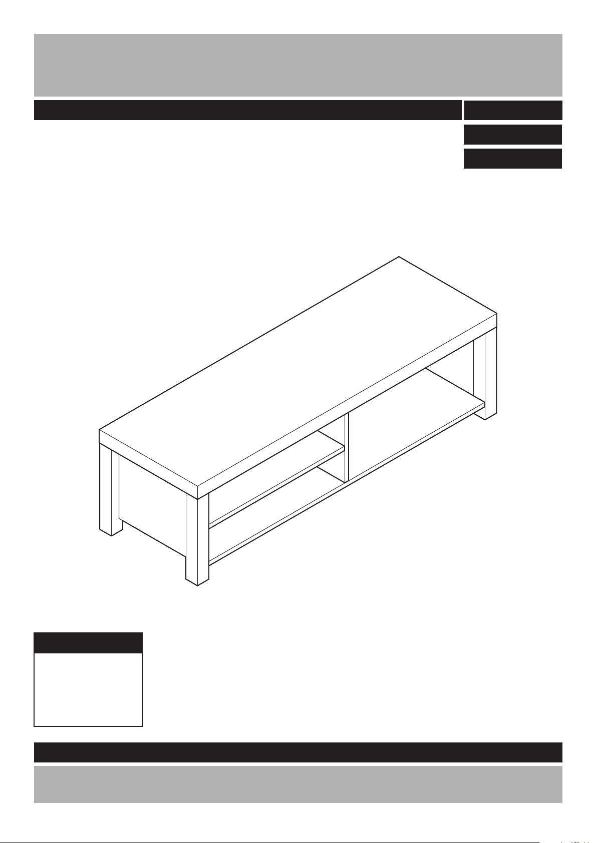
New Charlie TV Unit
Assembly Instructions
-
Please keep for future reference
609/7024
609/7031
609/7048
Dimensions
Width - 119 cm
Depth - 39 cm
Height - 34 cm
Important - Please read these instructions fully before starting assembly
If you need help or have damaged or missing parts, call the
Customer Helpline: 08456 400800
Version2 Date: 30/08/12
Page 2

Safety and Care Advice
Important - Please read these instructions fully before starting assembly
• Check you have all the
components and tools listed on
pages 2 and 3.
rom the
plastic bags and separate them
into their groups.
• Keep children and animals away
from the work area, small parts
could choke if swallowed.
• Make sure you have enough
space to layout the parts before
starting.
• Do not use this item if any
components are missing or
damaged.
• Do not stand on the product,
this could cause damage.
• Assemble the item as close to
room) as possible.
• Assemble on a soft level surface
to avoid damaging the unit or your
r.
• Parts of the assembly will be
easier with 2 people.
as this could damage the unit.
Only use hand screwdrivers.
• Dispose of all packaging
carefully and responsibly.
• Note: Only apply the glue once
you are sure of the assembly.
Glue safety - Take care when using glue, please follow the advice below
Skin contact: Remove
contamination by washing with
soap and water. This procedure
should also be followed prior to
eating and drinking.
Eye contact: Rinse immediately
with clean water for 15 minutes
and seek medical advice.
If swallowed: Seek medical
advice immediately.
• We do not
recommend the
use of power
drill/drivers for
inserting screws,
Care and maintenance
• Only clean using a damp cloth
and mild detergent, do not use
bleach or abrasive cleaners.
• From time to time check that
there are no loose screws on
this unit.
• This product should not be
discarded with household waste.
Take to your local authority waste
disposal centre.
Note: if required the next
page can be cut out and used
as reference throughout the
assembly. Keep this page with
these instructions for future
reference.
1
Page 3
If you have damaged or missing components,
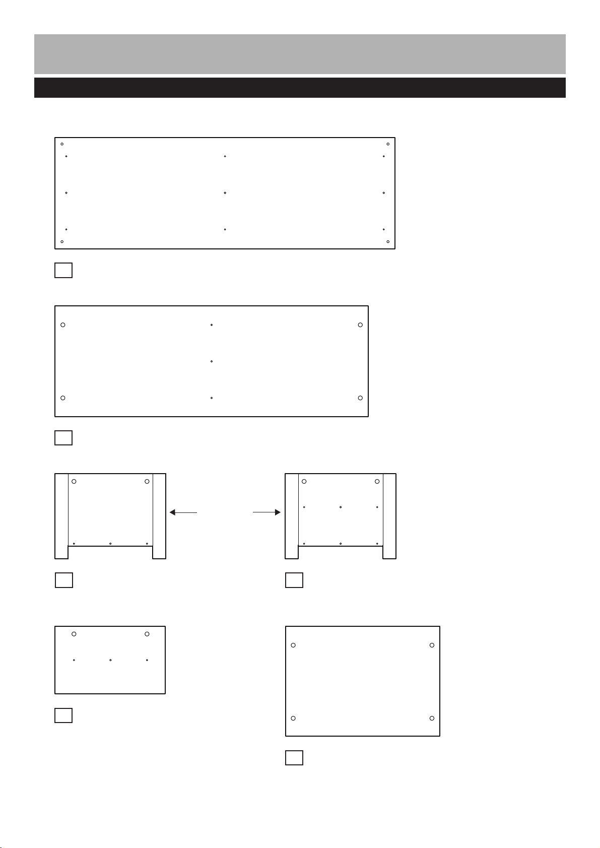
Components - Panels
call the Customer Helpline: 08456 400800
Please check you have all the panels listed below
Top panel (119 x 39cm)
1
Bottom panel
2
Right side panel
3
(38.8 x 29.8cm)
Middle panel
5
(38.6 x 23.7cm)
(109.6 x 38.7cm)
Finished
front edge
Left side panel
4
(38.8 x 29.8cm)
6
Shelf
(54 x 38.5cm)
2
Page 4

Components - Fittings
Note: The quantities below are the correct amount to complete the assembly. in some cases mor
may be supplied than are required.
A
39mm Locking pin x 8 15mm Locking nut x 14
D
30mm Dowel x 7
G
Feet x 1
B
43mm Locking pin x 6
E
40mm Dowel x 4
H
Glue x 1
C
F
50mm Screw x 3
Tools required
Phillips screwdriver
(medium & large)
Flatblade screwdriver
(medium)
Ruler - Use this ruler to help correctly identify the screws
0 5 10 15 20 25 30 35 40 45 50 55 60 65 70 75 80 85 90 95 100
3
Small
hammer
0 1 2 3 4 5 6
110 120 130 140 1500 10 20 30 40 50 60 70 80 90 100
Ruler/tape
measure
Eye protection
(when using a
hammer or glue)
105
110 115 120 125 130 135 140 145 150 155 160 165 170
Page 5

Assembly Instructions
Step 1
Attaching left side
panel
a:
Insert Dowels into
the Middle panel &
Shelf .
Screw Locking pins into
the Middle panel .
Note:
Insert Locking pins
as far as shown.
Do not over tighten.
6
D
5
A
5
a:
A
A
A
D
5
D
6
b:
Position
onto the Shelf
5
Insert 2 Locking nuts
into the
Use a screwdriver to turn
Locking nuts clockwise
to lock.
Middle panel
Shelf .
6
C
.
6
C
b:
D
Finished
front edge
C
5
C
6
C
Continued on next page.
4
Page 6

Assembly Instructions
Step 1 - continued
c:
Insert Dowels &
into the Left side panel
4
.
Screw Locking pins into
the Left side panel .
Note:
Insert Locking pins
as far as shown.
Do not over tighten.
d:
Position
4
onto the Shelf
D E
A
4
Left side panel
6
.
c:
E
d:
A
E
D
A
A
A
A
4
C
Insert 2 Locking nuts
into the Shelf .
Use a screwdriver to turn
Locking nuts clockwise
to lock.
6
C
C
Step 2
Attaching bottom
panle
a:
Insert Dowels into
the bottom panle .
D
2
a:
Finished
front edge
6
C
4
C
D
Finished
front edge
Continued on next page.
5
2
D
Page 7

Assembly Instructions
Step
b:
2
panel .
Insert 2 Locking nuts
into the Bottom panel .
2 - continued
Position
onto the Left side
Bottom panel
4
C
2
Use a screwdriver to turn
Locking nuts clockwise
C
to lock.
C
b:
Finished front edge
2
C
4
C
c:
Bottom panel
F
2
onto the
unit.
2
3
G
F
Fix Feet to Bottom
panel using Screw .
Step
Attaching right side
panel
a:
Insert Dowels &
D E
into the Right side panel
3
.
Screw Locking pins into
the Right side panel .
A
3
c:
a:
F
2
E
D
E
A
G
F
F
G
F
A
A
3
Note:
Insert Locking pins
as far as shown.
Do not over tighten.
Continued on next page.
6
Page 8

Assembly Instructions
Step 3 - continued
C
b:
Position
panel onto the Bottom
panel .
Insert 2 Locking nuts
into the Bottom panel .
Use a screwdriver to turn
Locking nuts clockwise
to lock.
Right side
3
2
C
2
C
b:
Finished
front edge
3
C
Step 4
Attaching top panel
a:
Screw Locking pins
into the Top panel .
Note:
Screw Locking pins
as far as shown.
Do not over tighten.
B
1
a:
2
B
B
B
B
1
C
B
Continued on next page.
7
B
B
Page 9

Assembly Instructions
Step 4 -
It would be useful
Note:
to ask someone to help
you at this stage.
b:
Place a small amount
of Glue onto the joint’s
surfaces.
continued
H
Carefully position Top
panel onto the unit.
Insert 6 Locking nuts into
the unit.
Use a screwdriver to turn
Locking nuts clockwise
to lock.
1
C
C
b:
3
4
Finished
front edge
H
H
5
C
H
1
C
C
C
3
5
C
Step 5
Finishing the unit
Note:
to ask someone to help
you at this stage.
With help, place the unit
in the intended position.
Note:
the glue to dry for 24
hours and make sure the
unit is secure.
It would be useful
Before use allow
C
C
4
Assembly is complete.
If you need help or have damaged or missing parts, call the Customer Helpline: 08456 400800
8
 Loading...