

Page 1
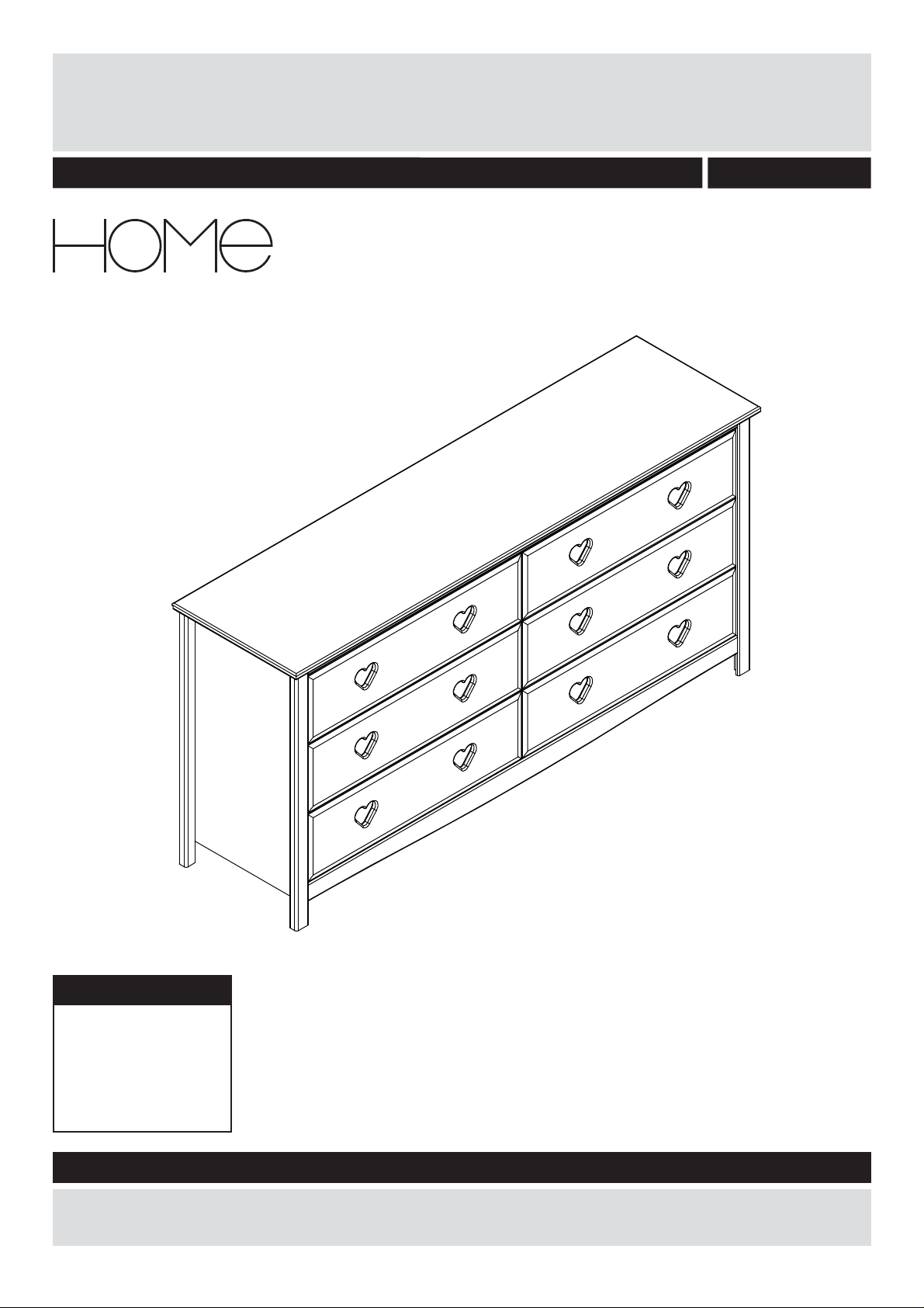
Mia 6 Drawer Chest - White
Assembly Instructions - Please keep for future reference
8573429
Dimensions
Length - 149.4cm
Depth - 40cm
Height - 73cm
Weight - 43kg
Important – Please read these instructions fully before starting assembly
If you need help or have damaged or missing parts, call the Customer Helpline:
0045 7668 8055 or e-mail: order@fl exa.dk
Issue 1 - 22/06/18
Page 2

Safety and Care Advice
Important – Please read these instructions
fully before starting assembly
• Check you have all the
components and tools listed on
pages 2 and 3.
• Remove all fi ttings from the
plastic bags and separate them
into their groups.
• During assembly children
should be kept away from the
product due to possible risk of
injury.
• Make sure you have enough
space to layout the parts before
starting.
•This product is suitable for
children in the age range 3 to
adult
Care and maintenance
• Only clean using a damp cloth
and mild detergent, do no use
bleach or abrasive cleaners.
• Regularly check all fastenings
to ensure that they properly
tightened.
• Do not stand or put weight on
the product, this could cause
damage.
• Assemble the item as close
to its fi nal position (in the same
room) as possible.
• Assemble on a soft level
surface to avoid damaging the
unit or your fl oor.
• Parts of the assembly will be
easier with 2 people.
• Do not use this item if any
components are missing or
damaged
• This product should not be
discarded with household waste.
Take to your local authority
waste disposal centre.
• We do not
recommend the
use of power
drill/drivers for
inserting screws,
as this could
damage the unit. Only use hand
screwdrivers.
• Dispose of all packaging
carefully and responsibly.
• Assembly to be carried out by
a competent adult only.
• This product is suitable for
children in the age 4-12 years.
Maximum load on chest 30 kg.
Maximum load in each drawer
7 kg.
1
Page 3
If you have damaged or missing components,
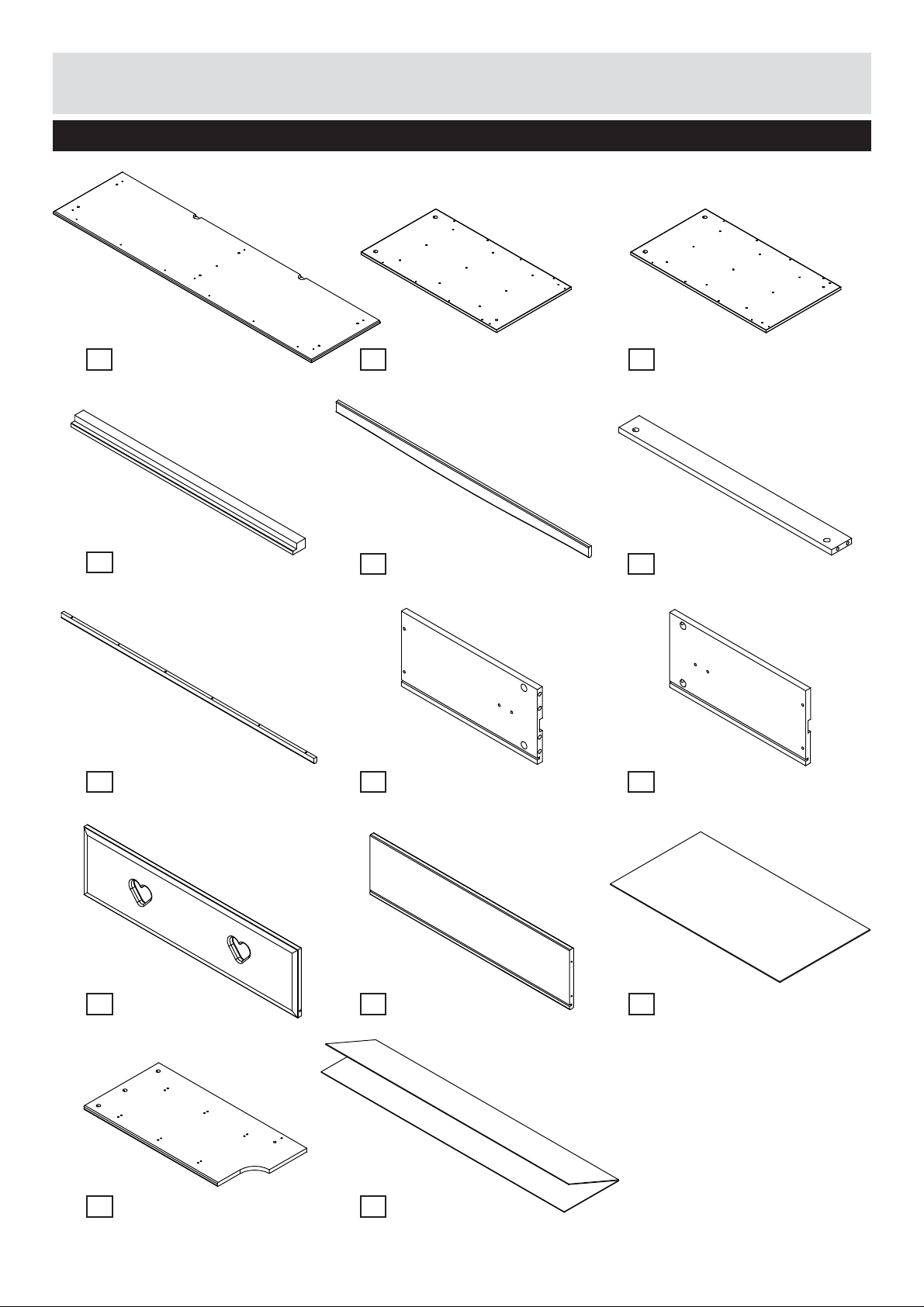
Components - Parts
call the Customer Helpline: 0045 7668 8055
Please check you have all the parts listed below
Top x1
1
(149.4x40.0x1.6cm)
No. 4301-1614941-40
Leg x4
4
(71.4x4.0x2.6cm)
No. 12-02607141-20
List Long x1
7
(138.2x2.5x1.5cm)
No. 12-01513822-40
Side panel Right x1
2
(65.4x36.1x1.2cm)
No. 4301-1206541-40 No. 4301-1206542-40
Plinth Curved x1
5
(138.2x6.5x1.5cm)
Drawer side Right x6
8
(35x16.7x1.3cm)
No. 15-01303503 No. 15-01303504
Side panel Left x1
3
(65.4x36.1x1.2cm)
Plinth Short x2
6
(68.3x6.5x1.5cm)
No. 12-01506831No. 12-01513821-40
Drawer side Left x6
9
(35x16.7x1.3cm)
Drawer front x6
10
(68.8x18.9x1.6cm)
No. 4301-1606887-40 No. 15-01306421 No. 4309-0306541
Partition x1
13
(71.4x36.1x1.6cm)
No. 4301-1607142-40 No. 4309-0314061
Drawer back x6
11
(64.2x16.7x1.3cm)
Back panel x1
14
(140.6x62.8/31.4x0.3cm)
Drawer base x6
12
(65.4x34.8x0.3cm)
2
Page 4
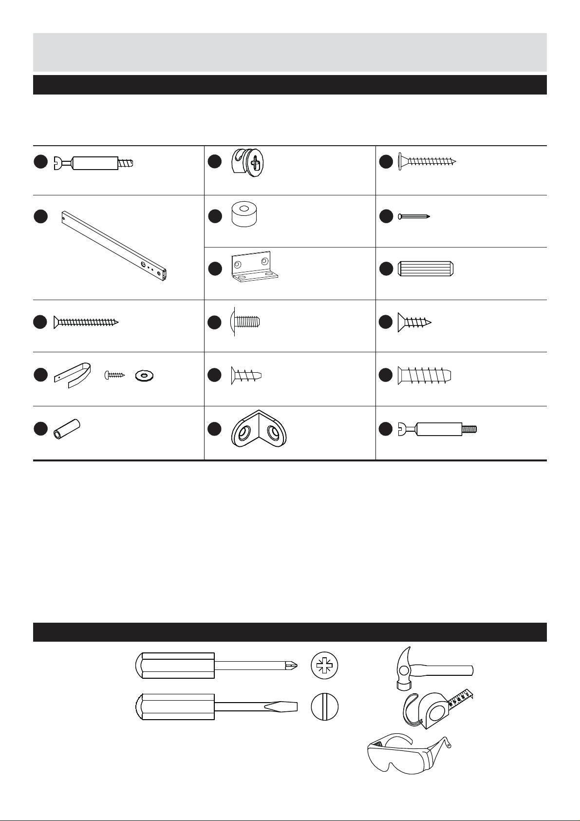
Components - Fittings
Please check you have all the fi ttings listed below
Note: The quantities below are the correct amount to complete the assembly. In some cases more fi ttings
may be supplied than are required.
No. 4020-007
A
Ø7x34mm Minifi x bolt x33
No. 4010-027
D
310x27x10mm Drawer slide x12
No. 3901-35035 No. 3912-04009
i
3.5x35mm Chipboard screw x30
No. 41-00179
L
Overbalance protector x2
No. 3924-04015
O
No. 3933-15010
B
Ø15x9.5mm Minifi x cam x35
No. 3940-00009
E
No. 4008-112
G H
44x23x23 Angle x2
J
Ø9.5/M4x9mm Machine screw x12
No. 3907-42010
M
Ø4.2x9.5mm Euro screw x8
No. 4008-037
P
No. 3903-40030
C
4.0x30mm Chipboard screw x16
No. 4022-004
F
1.6x16mm Nail square x48Ø18/Ø6,5x9.0mm Spacer x18
No. 3930-08030
Ø8x30mm Dowel x34
No. 3901-35012
K
3.5x12mm Chipboard screw x2
No. 3907-58019
N
Ø5.8x19mm Euro screw x30
No. 4020-006
Q
Ø5/M4x15mm Sleeve connector x1
Tools required
Phillips
screwdriver
(medium)
Flatblade
screwdriver
(medium)
21x21x16mm Angle x1
Ø7x34mm Minifi x bolt x2
Small
hammer
Ruler/tape
measure
Eye protection
(when using a
hammer or glue)
3
Page 5

Assembly Instructions
Step 1
Insert the dowels H into
the holes in short plinths
6
.
It may be necessary
to tap the dowels in
very gently with a small
hammer.
A
Attach minifi x bolts
1
top panel
.
to
A
A
H
A
A
A
A
A
A
H
H
1
H
H
6
6
Step 2
Attach the side panels
2
and 3 to the legs 4
C
using screws
Make sure the top of
the side panel is fl ush
with the legs and there
are no gaps between
the side panel and the
edge of the groove in
the legs.
.
C
C
C
C
2
4
4
C
3
4
2
C
C
C
C
4
C
4
2
C
UP
C
C
C
C
4
UP
C
C
4
Page 6

Assembly Instructions
Step 3
Insert the dowels H to
the holes in the side
2
panels
Attach minifi x bolts
the side panels
3
.
Attach the drawer
runners
panels
euro screws
from the third hole from
the front of the metal
runner
rest as instructed on the
pictures.
Note that the runners
need to be attached
with spacers
between the side panel
and runner.
Be aware of the front
edge!
and 3.
2
D
to the side
2
and 3 with
N
. Start
D
and align the
E
placed
A
to
and
A
H
Left side Right side
E
E
E
Front edge
3rd hole
3
E
N
E
E
N
H H
E
N
E
E
N
D D
N
D D
D D
A A
H
N
E
H
E
N
2
E
E
E
N
E
E
E
E
E
ForwardForward
Front edge
Step 4
H
Insert the dowels
the holes in the partition
13
.
Attach drawer runners
to the partition
euro screws
N
from the fi fth hole from
the front of the metal
D
runner
and align the
rest as instructed on the
pictures.
Be aware of the front
edge! Note that the
screws must be
inserted from different
holes in the runners!
into
13
with
. Start
D
Front edge
D
N
H
N
N
H
D
D
N
D
N
N
D
N
N
N
13
N
5th hole
Front edge
D
N
D
Front edge
5
Page 7

Assembly Instructions
Step 5
Attach second set of
D
13
with
N
. Start
to
drawer runners
the partition
euro screws
from the third hole from
the front of the metal
D
runner
and align the
rest as instructed on the
pictures.
Be aware of the front
edge! Note that the
drawer screws must be
inserted from different
holes in the runners!
Step 6
Insert sleeve connector
O
into the hole inside
13
partition
Attach minifi x bolts
the sleeve connector
inside partition
.
Q
to
O
13
.
N
13
Front edge
D
N
D
N
N
D
N
N
N
N
3rd hole
D
N
D
Front edge
O
Q
Step 7
Attach short plinths
the side panels
3
and partition 13 with
minifi x cams
2
B
.
6
and
to
13
Q
O
Q
B
2
13
6
B
3
6
B
B
B
6
Page 8

Assembly Instructions
Step 8
Attach the top 1 to the
2
side panels
and partition
minifi x cams
and 3
13
with the
B
.
Step 9
G
5
using
5
to the
to side
Attach angles
long plinth
M
screws
.
Attach plinth
2
panels
screws
and 3 using
M
.
B
B
B
3
13
M
G
M
5
1
B
B
B
B
2
G
M
G
2
G
5
3
5
M
M
7
Page 9

Assembly Instructions
Step 10
Fasten the list 7 to the
top panel using screws
i
, placing the screws
into the marking holes in
1
top
Attach long plinth
to the partition
angle
K
holes.
Don’t overtighten.
.
5
13
with
P
using screws
. Follow the marking
i
K
i
i
5
K
13
K
P
7
i
13
1
i
P
i
i
Step 11
Attach the back panel 14
F
with nails
side of the chest.
Nail the back panel
to the carcass, ensuring
that there are NO GAPS
between the top
the back panel
Follow the
measurements.
to the back
14
1
and
16
.
28 mm
5
F
28 mm
F
14
28 mm
28 mm
8
Page 10

Assembly Instructions
Step 12a
Measure out the
positions for the wall
attachment straps.
Drill two holes spaced
as illustrated with the
appropriate size for the
wall attachment fi tting
(see next step).
Pull the two straps
through the gaps in
1
top plate
furniture against the wall
and secure the strap
under the top plate with
washer and screw.
.Push the
L
L
L
1
60,5 cm
69 cm
L
Step 12b
Different types of wall
fi ttings. Contact your
local DIY or hardware
store for the wall plugs
and screws.
Concrete/Brick wall
Plaster wall
Wooden wall
9
Page 11

Assembly Instructions
Step 13
Insert the dowels H into
the holes in the drawer
8
sides
and 9.
Attach the minifi x bolts
10
to the drawer front
.
Repeat for all drawer
sides and drawer
fronts.
Step 14a
Attach the drawer sides
8
and 9 to the drawer
10
front
cams
Repeat for all drawers.
with the minifi x
B
.
A
A
H
B
8
9
H
A
10
B
A
10
B
B
A
A
9
Step 14b
Push the drawer base
carefully into the drawer.
Attach the drawer back
11
to the drawer sides
8
and 9 with the
i
screws
.
Repeat for all drawers.
12
8
i
9
10
12
8
i
11
i
i
i
10
Page 12

Assembly Instructions
Step 15
Place the assembled
drawer between the
D
drawer runners
Attach the drawer sides
8
and 9 to the runners
using the screws
Repeat for all drawers.
.
J
.
J
J
8
J
9
J
9
Assembly is complete.
If you need help or have damaged or missing parts,
E-mail: order@fl exa.dk
11
Ref.no. 44-01803-20 A Stand: 220618 Page 12 (81-31308-20)
call the Customer Helpline: 0045 7668 8055
Page 13

 Loading...