

Page 1
SurroundVideo®!G5
Installation Manual!
Models:
5 Megapixel
• AV5585PM
12 Megapixel
• AV12585PM
• AV12586PM
20 Megapixel
• AV20585PM
!
Page 2

!! ! Installation!Manual!
Page | 2 support@arecontvision.com
!
!
+1.818.937.0700 877.CAMERA.8 www.arecontvision.com avsales@arecontvision.com
SurroundVideo®!G5
!
Contents
!
Package Contents!..................................................................................................................................................!3!
In-ceiling Mount!......................................................................................................................................................!9!
Mounting Recommendations!..............................................................................................................................!14!
Pendant Mount!.....................................................................................................................................................!16!
Surface Mount!......................................................................................................................................................!17!
Wall Mount!............................................................................................................................................................!19!
Pole Mount!............................................................................................................................................................!20!
Corner Mount!........................................................................................................................................................!22!
Electrical Box Adapter!.........................................................................................................................................!24!
Adjusting the Pan, Tilt and Focus!......................................................................................................................!25!
Optional: Connecting Digital I/O!.........................................................................................................................!27!
Connecting Heater and Blower!..........................................................................................................................!29!
Camera Discovery, Setup, and Configuration!.................................................................................................!32!
Network Protocols!................................................................................................................................................!32!
General Remote Focus!.......................................................................................................................................!33!
AV IP Utility Focus Tab ........................................................................................................................... 34
Support!..................................................................................................................................................................!35!
!
!
Page 3
!! ! Installation!Manual!
Page | 3 support@arecontvision.com
!
!
+1.818.937.0700 877.CAMERA.8 www.arecontvision.com avsales@arecontvision.com
SurroundVideo®!G5
'
CAUTION!
1. Do not attempt to service a damaged unit yourself. Refer all servicing to qualified service
personnel.
2. Wiring methods shall be in accordance with the National Electrical Code/NFPA 70/ANSI, and
with all local codes and authorities having jurisdiction. Wiring should be UL Listed and/or
Recognized wire suitable for the application.
3. Always use hardware e.g. screws, anchors, bolts, locking nuts etc. which are compatible with
mounting surface and of sufficient length and construction to insure a secure mount.
Package Contents
This equipment should be unpacked and handled with care. The original packaging is the safest
container in which to transport the unit and can be used if returning the unit for service. The packaging
contains:
• One (1) Arecont Vision SurroundVideo® G5 Camera
• One (1) mounting template
• Four (4) Mounting Wood Screws
• Four (4) Mounting Dry Wall Anchors
• One (1) RJ45 Female to female coupler
• One (1) Security L-key
• One (1) Hex key
!
!
!
!
Page 4

!! ! Installation!Manual!
Page | 4 support@arecontvision.com
!
!
+1.818.937.0700 877.CAMERA.8 www.arecontvision.com avsales@arecontvision.com
SurroundVideo®!G5
Warranty Information
Global (3 Year) Limited Warranty
ARECONT VISION warrants to Purchaser (and only Purchaser) (the “Limited Warranty”), that: (a) each
Product shall be free from material defects in material and workmanship for a period of thirty-six (36)
months from the date of shipment (the “Warranty Period”); (b) during the Warranty Period, the
Products will materially conform with the specification in the applicable documentation; (c) all licensed
programs accompanying the Product (the “Licensed Programs”) will materially conform with applicable
specifications. Notwithstanding the preceding provisions, ARECONT VISION shall have no obligation or
responsibility with respect to any Product that (i) has been modified or altered without ARECONT
VISION’s written authorization; (ii) has not been used in accordance with applicable documentation; (iii)
has been subjected to unusual stress, neglect, misuse, abuse, improper storage, testing or connection;
or unauthorized repair; or (iv) is no longer covered under the Warranty Period. ARECONT VISION
MAKE NO WARRANTIES OR CONDITIONS, EXPRESS, IMPLIED, STATUTORY OR OTHERWISE,
OTHER THAN THE EXPRESS LIMITED WARRANTIES MADE BY ARECONT VISION ABOVE, AND
ARECONT VISION HEREBY SPECIFICALLY DISCLAIMS ALL OTHER EXPRESS, STATUTORY AND
IMPLIED WARRANTIES AND CONDITIONS, INCLUDING THE IMPLIED WARRANTIES OF
MERCHANTABILITY, FITNESS FOR A PARTICULAR PURPOSE, NON-INFRINGEMENT AND THE
IMPLIED CONDITION OF SATISFACTORY QUALITY. ALL LICENSED PROGRAMS ARE LICENSED
ON AN “AS IS” BASIS WITHOUT WARRANTY. ARECONT VISION DOES NOT WARRANT THAT (I)
THE OPERATION OF THE PRODUCTS OR PARTS WILL BE UNINTERRUPTED OR ERROR FREE;
(II) THE PRODUCTS OR PARTS AND DOCUMENTATION WILL MEET THE END USERS’
REQUIREMENTS; (III) THE PRODUCTS OR PARTS WILL OPERATE IN COMBINATIONS AND
CONFIGURATIONS SELECTED BY THE END USER; OTHER THAN COMBINATIONS AND
CONFIGURATIONS WITH PARTS OR OTHER PRODUCTS AUTHORIZED BY ARECONT VISION
OR (IV) THAT ALL LICENSED PROGRAM ERRORS WILL BE CORRECTED.
For RMA and Advance Replacement information visit http://www.arecontvision.com
!
Page 5

!! ! Installation!Manual!
Page | 5 support@arecontvision.com
!
!
+1.818.937.0700 877.CAMERA.8 www.arecontvision.com avsales@arecontvision.com
SurroundVideo®!G5
Camera Overview!
The SurroundVideo® G5 multi-sensor, multi-megapixel dome camera pushes the boundaries of next
generation technology, providing users with four (4) integrated, motorized P-iris lenses for an incredible
180° panoramic experience in a single indoor/outdoor housing. SurroundVideo® G5 cameras provide
an all-in-one solution for capturing wide area video surveillance while maximizing the field-of-view and
reducing the total number of cameras required.
The SurroundVideo® G5 multi-megapixel camera series delivers 5-, 12-, or 20-megapixel resolutions.
For added flexibility, users can view the camera’s four (4) sensors individually or as a smooth transition
of all images blended together for a full 180° panoramic view. The camera is factory aligned with a
slight image overlap to ensure you never miss a thing.
The series combines a day/night mechanical IR cut filter for the highest image quality at any time of
day. The SurroundVideo® G5 camera features four (4) factory-installed P-iris lenses, ensuring the best
possible depth of field and image clarity for precise performance from each individual sensor. Once
mounted, the operator can quickly focus and position the camera remotely, eliminating the need to
adjust the camera on-site. No more hassle individually installing multiple cameras to cover a wide area,
manually focusing lenses, or risk missing critical information.
SurroundVideo® G5 is designed for demanding environments. Subjected and certified to rigorous dust
and water tests, the IP66 rating, and its extended operating temperature range make it ideal for outdoor
applications. The IK-10 rated, rugged dome housing is perfect for deterring vandals since it can
withstand the equivalent of 55 kg (120 lbs) of force.
Page 6
!! ! Installation!Manual!
Page | 6 support@arecontvision.com
!
!
+1.818.937.0700 877.CAMERA.8 www.arecontvision.com avsales@arecontvision.com
SurroundVideo®!G5
Installation
1. Determine a secure location to mount the camera.
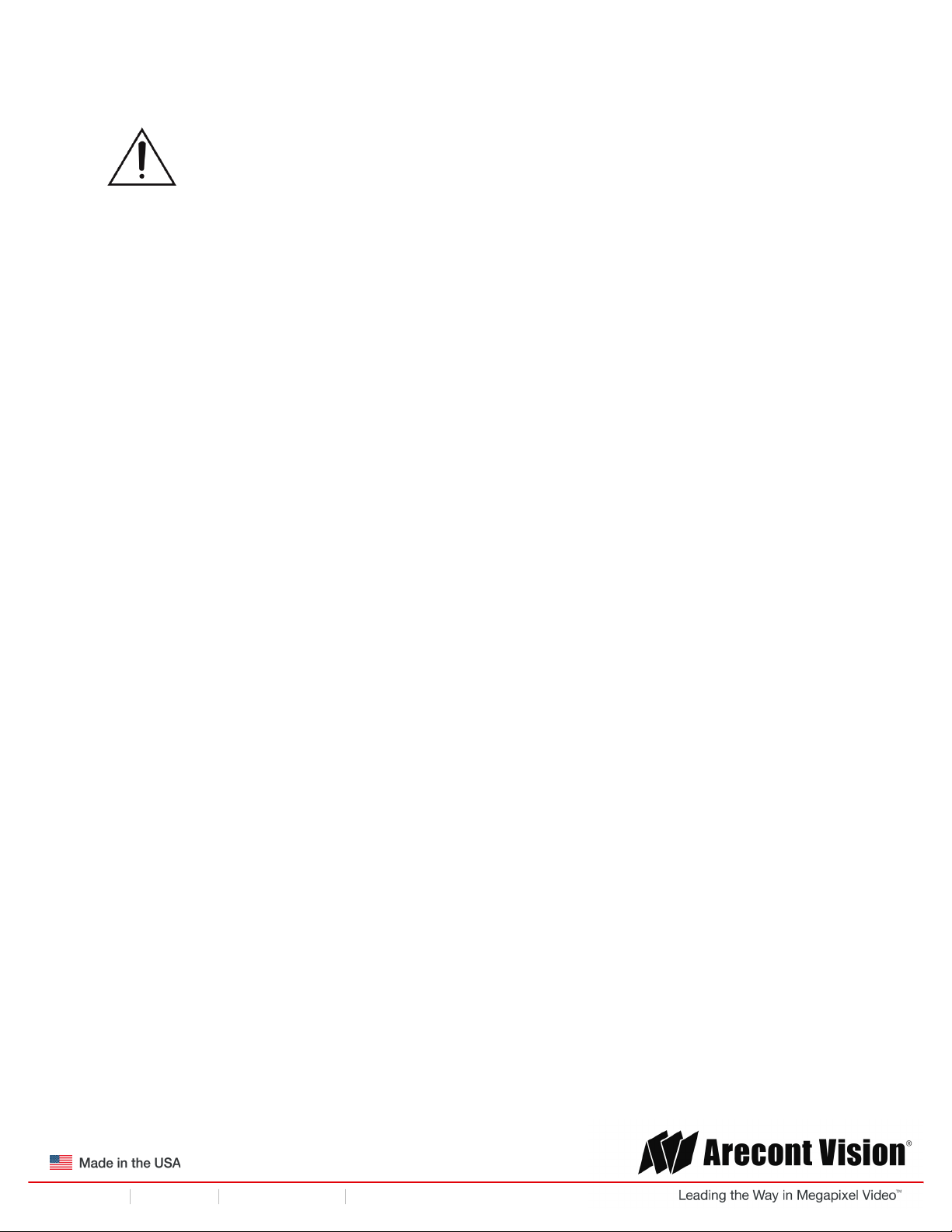
2. Use the supplied security L-key, to loosen the four (4) screws securing the dome cover (Figure
1). Remove dome cover. Do not remove screws from the dome cover.
Figure 1: Remove dome cover
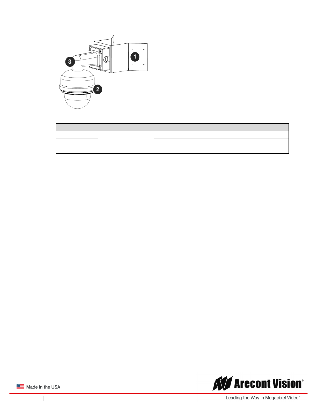
3. The SurroundVideo® G5 camera has been designed to provide installers with flexible mounting
options such as ceilings, walls, poles or corners. Choose the best method for your installation:
Remove for in-ceiling installation
!
Pendant mount
Reference #
Mount Type
Parts Required
1
In-ceiling mount
Remove surface mount portion of camera
2
+ SV-FMA flush mount adapter
3
Pendant mount
AV-PMJB pendant mount
4
+ SV-CAP mount cap
Page 7
!! ! Installation!Manual!
Page | 7 support@arecontvision.com
!
!
+1.818.937.0700 877.CAMERA.8 www.arecontvision.com avsales@arecontvision.com
SurroundVideo®!G5
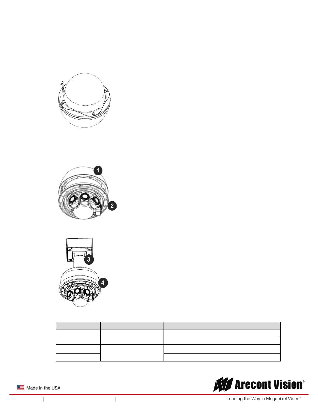
Wall mount
Reference #
Mount Type
Parts Required
1
Wall mount
AV-WMJB
2
+ SV-CAP mount cap
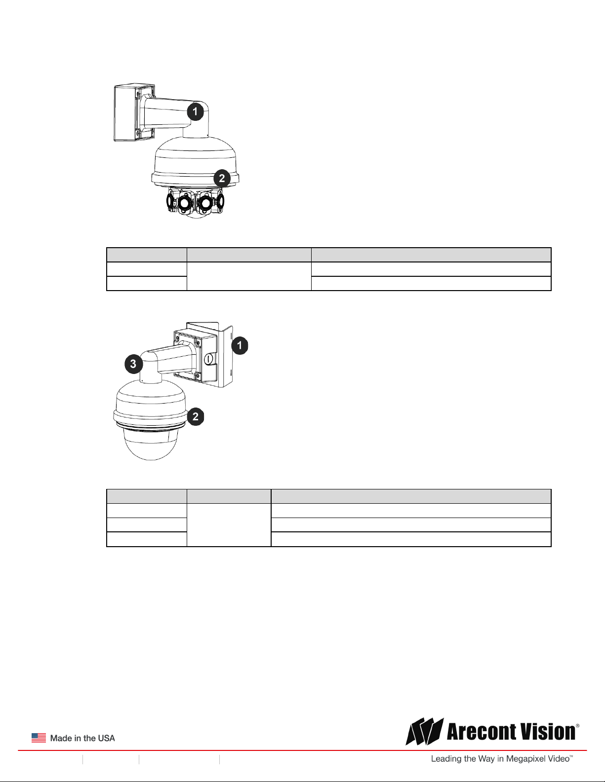
Pole mount
Reference #
Mount Type
Parts Required
1
Pole mount
AV-PMA
2
+ SV-CAP mount cap
3
+ AV-WMJB
Page 8
!! ! Installation!Manual!
Page | 8 support@arecontvision.com
!
!
+1.818.937.0700 877.CAMERA.8 www.arecontvision.com avsales@arecontvision.com
SurroundVideo®!G5
Corner mount
Reference #
Mount Type
Parts Required
1
Corner mount
AV-CRMA
2
+ SV-CAP mount cap
3
+ AV-WMJB
NOTE: It is recommended to conduct periodic inspections of the installation. Rust on the metal
parts or screws may result in damage to the camera.
4. Use the Arecont Vision software AV IP Utility located on the CD or available for download at our
website (www.arecontvision.com) for camera discovery and setup (see Instruction Manual
located on the CD or available on our website).
Page 9
!! ! Installation!Manual!
Page | 9 support@arecontvision.com
!
!
+1.818.937.0700 877.CAMERA.8 www.arecontvision.com avsales@arecontvision.com
SurroundVideo®!G5
In-ceiling Mount
To properly flush mount the SurroundVideo® G5 to a drop ceiling or similar surface, a flush mount
adapter kit (SV-FMA) is required (sold separately). An in-ceiling mount should only be attached onto
hard ceilings including wood, plastic, metal and concrete.
1. Cut a hole in the ceiling using the template provided to fit the camera housing.
NOTE: SurroundVideo® G5 ships with both surface mount and in-ceiling mount, the mounting
template takes both into consideration.
2. Loosen the four (4) machine screws with user-supplied #2 Phillips head screwdriver and remove
the in-ceiling mount housing from the surface mount housing (see Figure 4). Set surface mount
housing aside for future use.
Figure 3: Remove four (4) screws
NOTE: The above removed screws are also used to attach the camera with in-ceiling mount
housing to the pendant mount and wall mount. Do not discard.
Page 10
!! ! Installation!Manual!
Page | 10 support@arecontvision.com
!
!
+1.818.937.0700 877.CAMERA.8 www.arecontvision.com avsales@arecontvision.com
SurroundVideo®!G5
Figure 4: Remove in-ceiling mount from surface mount housing
Reference #
Description
1
In-ceiling mount
2
Surface mount
Page 11
!! ! Installation!Manual!
Page | 11 support@arecontvision.com
!
!
+1.818.937.0700 877.CAMERA.8 www.arecontvision.com avsales@arecontvision.com
SurroundVideo®!G5
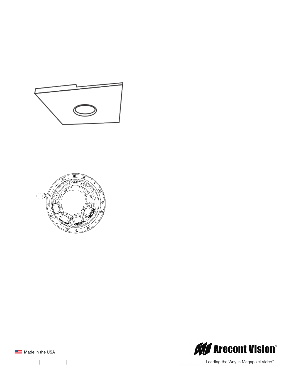
3. Attach the Flange Plate to the in-ceiling mount with the 3 set screws as shown in Figure 5.
Figure 5: Attach Flange Plate to in-ceiling mount with 3 set screws
4. Attach Top Plate to in-ceiling mount with other 3 set screws as shown in Figure 6.
Figure 6: Attach Top Plate to in-ceiling mount with 3 set screws
Reference #
Description
1
In-ceiling mount
2
Flange Plate
3
Top Plate
Page 12

!! ! Installation!Manual!
Page | 12 support@arecontvision.com
!
!
+1.818.937.0700 877.CAMERA.8 www.arecontvision.com avsales@arecontvision.com
SurroundVideo®!G5
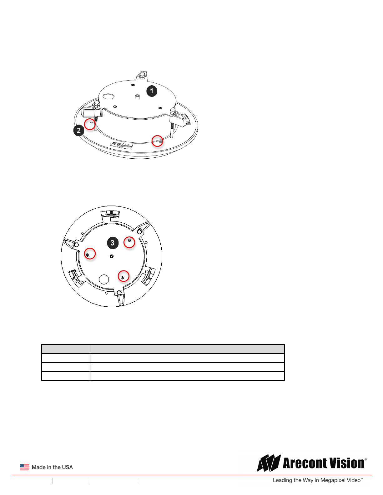
4. Insert each lever screw into the Flange Plate, support arm, and Top Plate. Then, screw the nuts
and caps as shown in Figure 7.
Figure 7: Attach the 3 levers
5. Insert the Flush Mount Adapter (SV-FMA: sold separately) into the hole.
6. Screw the “lever screws” until the flush mount is snuggly installed, as shown in Figure 8. The
“Support Arm” will ride down the screw to compress the mounting surface (Figure 9).
Figure 8: Attach Top Plate to in-ceiling mount with 3 set screws
NOTE: Do not over-torque the lever screws
Page 13

!! ! Installation!Manual!
Page | 13 support@arecontvision.com
!
!
+1.818.937.0700 877.CAMERA.8 www.arecontvision.com avsales@arecontvision.com
SurroundVideo®!G5
Figure 9: Compress the mounting surface with lever screws
Reference #
Description
1
Support Arm
2
Lever Screw
3
Flange Plate
4
Trim Ring
7. To configure the camera, reference the set-up section.
8. Attach the Trim Ring to the Flush Mount Adapter by rotating clockwise as show in Figure 10.
Figure 10: Attach Trim Ring to the Flush Mount Adapter clockwise
Page 14

!! ! Installation!Manual!
Page | 14 support@arecontvision.com
!
!
+1.818.937.0700 877.CAMERA.8 www.arecontvision.com avsales@arecontvision.com
SurroundVideo®!G5
Mounting Recommendations
For the best visibility toward the target, and a minimal blind spot below the camera, Arecont Vision
recommends mounting panoramic cameras 15-20ft off the ground. If the application is unable to meet
this criteria, for every 10ft the camera is mounted from the ground, expect a 10ft blind spot below, and
the camera should be aimed ~100ft, for every 10ft mounted from the ground, toward the horizon.
For example, a camera mounted at 30ft will have a 30ft blind spot below the camera and should be
aimed 300ft toward the horizon. In the example below, the camera in Figures 10B and 10C are both
mounted 30ft high; however, the camera in Figure 10B is aimed 250ft toward the horizon and the
camera in Figure 10C is only aimed 150ft toward horizon. As a result, the camera in Figure 10C will
have less than desirable results due to its higher curvature.
Figure 10A: Recommended height for panoramic cameras
!
Figure 10B: Less curvature provides better results
!
Figure 10C: Higher curvature produces less desirable results
Page 15

!! ! Installation!Manual!
Page | 15 support@arecontvision.com
!
!
+1.818.937.0700 877.CAMERA.8 www.arecontvision.com avsales@arecontvision.com
SurroundVideo®!G5
In the example below, the camera in Figures 10D and 10E are both mounted 8ft high; however, the
camera in Figure 10D is aimed 80ft toward the horizon and the camera in Figure 10E is only aimed at
30ft toward horizon. The camera in Figure 10E results in a drastic curvature with less usable video.
Figure 10D: Mounting height of 8ft and aimed 80ft toward horizon
Figure 10E: Mounting height of 8ft and aimed only 30ft toward horizon
!
Page 16

!! ! Installation!Manual!
Page | 16 support@arecontvision.com
!
!
+1.818.937.0700 877.CAMERA.8 www.arecontvision.com avsales@arecontvision.com
SurroundVideo®!G5
Pendant Mount
For a proper pendant mount installation, the AV-PMJB pendant mount and SV-CAP mount cap are
required (sold separately). A pendant mount should only be attached onto hard ceilings including wood,
plastic, metal, and concrete.
1. Using the mounting template, prepare the mounting provisions for the camera installation.
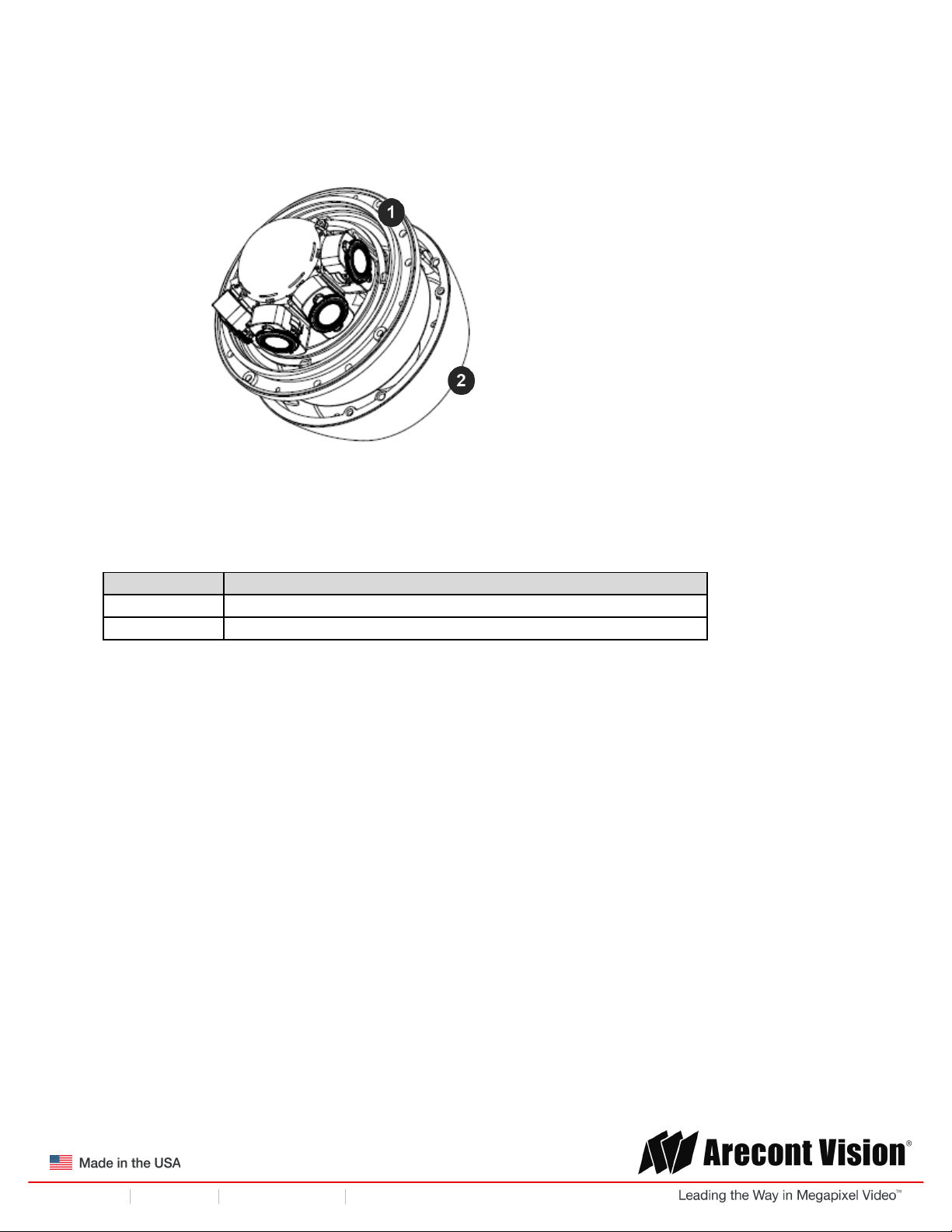
2. Connect top shield, pendant pole and mount together as shown in Figure 11.
Figure 11: Attach the mount cap and pole
NOTE: The thread size of top shield, pendant pole and mount is 1.5” NPT.
3. Attach the pendant mount to the ceiling using the four wood screws provided or any optional
hardware suitable for the mounting surface.
4. Run the Ethernet Cable and outside power cable (if necessary) through the pendant.
Figure 12: Attach camera
5. To configure the camera, reference the camera discovery, set-up and configuration section.
Page 17

!! ! Installation!Manual!
Page | 17 support@arecontvision.com
!
!
+1.818.937.0700 877.CAMERA.8 www.arecontvision.com avsales@arecontvision.com
SurroundVideo®!G5
Surface Mount
The SurroundVideo® G5 can be directly attached onto hard ceilings or walls including wood, plastic,
metal and concrete.
1. Use the template provided to prepare the mounting provisions for the camera installation.
NOTE: SurroundVideo® G5 ships with both surface mount and in-ceiling mount, the mounting
template takes both into consideration.
2. Loosen the four (4) machine screws with user-supplied #2 Phillips head screwdriver.
Figure 3: Remove four (4) screws
NOTE: The above removed screws are also used to attach the camera with in-ceiling mount
housing to the pendant mount and wall mount. Do not discard.
3. Remove the in-ceiling housing from the surface mount housing. Set the in-ceiling housing aside.
!
Figure 4: Remove in-ceiling mount from surface mount housing
Reference #
Description
1
In-ceiling mount
2
Surface mount
Page 18

!! ! Installation!Manual!
Page | 18 support@arecontvision.com
!
!
+1.818.937.0700 877.CAMERA.8 www.arecontvision.com avsales@arecontvision.com
SurroundVideo®!G5
Figure 5: Mount the Surface mount to the wall or ceiling
NOTE: If you use the side connection of the NPT port, remove the cap covering the side
entrance, otherwise; leave the cap in place. If using the NPT port, always use Teflon tape
around the threads to ensure proper sealing. The conduit fits ¾” NPT standard. Ensure NPT
port is facing downward.
4. Route the cable tree from the camera around the rear of the camera module and secure all
cables. See the Connections section for details on how to connect the camera.
5. Check that the indicator LED’s are illuminated to the desired conditions (see LED Indicator
table).
CAUTION! The captive fasteners must be used to properly secure the dome cover. Failure
to use the captive fastener may result in serious injury. When mounting the dome cover to
the camera housing, ensure that the gasket is properly seated and not folded. Failure to
do so may result in water and dust ingress. Water damage from improper installation is not
covered by the warranty!
Page 19

!! ! Installation!Manual!
Page | 19 support@arecontvision.com
!
!
+1.818.937.0700 877.CAMERA.8 www.arecontvision.com avsales@arecontvision.com
SurroundVideo®!G5
Wall Mount
For a proper wall mount installation, the AV-WMJB wall mount and SV-CAP wall mount cap are
required (sold separately). A wall mount should only be attached onto hard ceilings including wood,
plastic, metal, and concrete.
1. Using the Mounting template, prepare the mounting provisions for the camera installation.
2. Connect wall mount cap and wall mount as shown in Figure 13.
Figure 13: Attach wall mount cap to the wall mount
NOTE: The thread size for Top shield, pendant pole and mount is 1.5” NPT.
3. Run Ethernet Cable and outside power cable (if necessary) through the Wall Mount.
4. Attach the wall mount to the wall using drywall screws or any optional hardware suitable for the
mounting surface.
Figure 14: Attach camera
5. To configure the camera, reference the camera discovery, set-up and configuration section.
Page 20

!! ! Installation!Manual!
Page | 20 support@arecontvision.com
!
!
+1.818.937.0700 877.CAMERA.8 www.arecontvision.com avsales@arecontvision.com
SurroundVideo®!G5
Pole Mount
For a pole mount installation, the AV-WMJB wall mount, AV-PMA pole mount, and SV-CAP mount cap
are required (sold separately). A pole mount should only be attached onto hard ceilings including wood,
plastic, metal, and concrete.
1. Using the mounting template, prepare the mounting provisions for the camera installation.
2. Connect the wall mount cap and wall mount as shown in Figure 13.
3. Attach the AV-JBA (Junction Box Adapter) to the Pole Mount Adapter (Figure 15).
4. Remove the conduit plug on the junction box adapter and connect ¾” NPT conduit to the
junction box adapter (Figure 15).
Figure 15: Attach conduit to AV-JBA junction box adapter
Reference #
Description
1
Remove conduit plug
2
Connect ¾” NPT conduit to junction box adapter (ensure
use of water seal tape)
NOTE: Use silicon or water pipe seal tape to make sure no water leakage between conduit pipe
and junction box adapter.
5. Run the Ethernet cable and outside power cable (if necessary) through the Junction Box
Adapter and SV-WMJB, Wall Mount Adapter.
6. Attach the Wall Mount Adapter (SV-WMJB) to the Pole Mount Adapter (AV-PMA) as shown in
Figure 16.
Page 21

!! ! Installation!Manual!
Page | 21 support@arecontvision.com
!
!
+1.818.937.0700 877.CAMERA.8 www.arecontvision.com avsales@arecontvision.com
SurroundVideo®!G5
Figure 16: Attach wall mount adapter to pole mount adapter
Reference #
Description
1
Steel straps with compression screws
2
AV-WMJB wall mount
3
SV-CAP mount cap
4
Conduit
5
AV-PMA pole mount
6
AV-JBA Junction box
7
Apply Teflon water seal tape to the thread of ¾” NPT pipe
to avoid water leakage
7. Use the supplied two Steel Straps to attach the Pole Mount Adapter to the pole and tighten the
compression screws as shown in Figure 16.
8. Attach the camera with the in-ceiling mount to the Wall Mount Adapter.
9. To configure the camera, reference the camera discovery, set-up and configuration section.
Page 22

!! ! Installation!Manual!
Page | 22 support@arecontvision.com
!
!
+1.818.937.0700 877.CAMERA.8 www.arecontvision.com avsales@arecontvision.com
SurroundVideo®!G5
Corner Mount
For a corner mount installation, the AV-WMJB wall mount, AV-CRMA corner mount, and SV-CAP
mount cap are required (sold separately). A corner mount should only be attached onto hard corner
surfaces including wood, plastic, metal, and concrete.
1. Using the Mounting template, prepare the mounting provisions for the camera installation.
2. Connect the wall mount cap and wall mount as shown in Figure 13.
3. Attach the AV-JBA (Junction Box Adapter) to the Corner Mount Adapter (Figure 16).
4. Remove the conduit plug on the junction box adapter and connect ¾” NPT conduit to the
junction box adapter (Figure 16).
! !
Figure 16: Attach conduit to AV-JBA junction box adapter
Reference #
Description
1
Remove conduit plug
2
Connect ¾” NPT conduit to junction box adapter (ensure
use of water seal tape)
NOTE: Use silicon or water pipe seal tape to make sure no water leakage between conduit pipe
and junction box adapter.
5. Run the Ethernet cable and outside power cable (if necessary) through the Junction Box
Adapter and SV-WMJB, Wall Mount Adapter.
6. Attach the Wall Mount Adapter (SV-WMJB) to the Corner Mount Adapter (AV-CRMA) as shown
in Figure 17.
Page 23

!! ! Installation!Manual!
Page | 23 support@arecontvision.com
!
!
+1.818.937.0700 877.CAMERA.8 www.arecontvision.com avsales@arecontvision.com
SurroundVideo®!G5
Figure 17: Attach corner mount adapter to exterior corner wall
Reference #
Description
1
Attach corner mount adapter to exterior 90° corner wall
2
AV-WMJB wall mount
3
SV-CAP mount cap
4
Conduit
5
AV-CRMA corner mount adapter
6
AV-JBA Junction box
7
Apply Teflon water seal tape to the thread of ¾” NPT pipe
to avoid water leakage
7. Using the screws provided (or other hardware), attach the Corner Mount Adapter to an exterior
90° corner wall.
8. Attach camera with in-ceiling mount to Wall Mount Adapter.
9. To configure the camera, reference the camera discovery, set-up and configuration section.
Page 24

!! ! Installation!Manual!
Page | 24 support@arecontvision.com
!
!
+1.818.937.0700 877.CAMERA.8 www.arecontvision.com avsales@arecontvision.com
SurroundVideo®!G5
Electrical Box Adapter
The AV-EBA electrical box adapter is used to attach the camera to a common single, double or square
electrical box.
1. Using the AV-EBA’s supplied machine screws, match the mounting holes on the adapter with
the threaded holes on the electrical box. Ensure every threaded hole is matched with a
mounting hole.
2. Attach the electrical box adapter to the user supplied electrical box.
Figure 17: Attach AV-EBA adapter to common electrical box
Reference #
Description
1
AV-EBA electrical adapter plate
2
Common electrical box (single, double or square gang
box)
Page 25

!! ! Installation!Manual!
Page | 25 support@arecontvision.com
!
!
+1.818.937.0700 877.CAMERA.8 www.arecontvision.com avsales@arecontvision.com
SurroundVideo®!G5
Adjusting the Pan, Tilt and Focus
1. Remove the dome cover by loosening the captive fasteners with the supplied Philips head
screwdriver.
2. Power on the camera to adjust the pan, tilt and focus.
3. To adjust the pan, use a #2 Phillips screwdriver to loosen both screws on the sides of the plastic
gimbal bracket as shown in Figure 18.
Figure 18: Loosen both screws aside of gimbal bracket
4. Adjust the pan as required and re-tighten the screw (Figure 19).
!
Figure 19: Adjust the pan and re-tighten the screws
Reference #
Description
1
Adjustable 360°
Page 26

!! ! Installation!Manual!
Page | 26 support@arecontvision.com
!
!
+1.818.937.0700 877.CAMERA.8 www.arecontvision.com avsales@arecontvision.com
SurroundVideo®!G5
5. To adjust the tilt, use a #2 Phillips screwdriver to loosen both screws on the sides of the plastic
gimbal bracket 1/4 turn (Figure 20). NOTE: Do not remove the screws!
Figure 20: Loosen both screws on the gimbal bracket
6. Adjust lens tilt as required and re-tighten the screws (Figure 21).
!
Figure 21: Adjust lens tilt and re-tighten the screws
Reference #
Description
1
Adjustable 90°
NOTE: The camera has a 2-Axis gimbal with 360° pan and 90° tilt for easy and accurate
positioning.
7. To adjust the focus, see the Remote Focus Section of this manual.
Page 27

!! ! Installation!Manual!
Page | 27 support@arecontvision.com
!
!
+1.818.937.0700 877.CAMERA.8 www.arecontvision.com avsales@arecontvision.com
SurroundVideo®!G5
Optional: Connecting Digital I/O
To use digital I/O, connect digital I/O with pigtail cable connector as shown below.
Reference #
Description
1
Input (White + / Black -)
2
Output (Orange + / Yellow -)
NOTE: SurroundVideo® G5 supports digital input and digital output. See Table 1 for electrical
characteristics.
Electrical Characteristics
MIN
MAX
Input Voltage (V)
(Measured between +
and – terminals)
ON
3.5
6.3
OFF
0
1.3
Output Current (mA)
(Measured between +
and – terminals)
Applied Voltage
Range: 0-80V
ON - 50
OFF
-
0.1
Table'1'
!
NOTE: The digital input is electrically isolated from the rest of the camera’s electrical circuitry via
general-purpose photo couplers. The input is additionally protected with a serial 250 Ohm resistor, and
a de-bouncing circuit. Duration of any input signal should be at least 5 ms to comply with the
requirements of the de-bouncing circuit.
NOTE: Table 2 shows the cable color for digital input and output.
Page 28

!! ! Installation!Manual!
Page | 28 support@arecontvision.com
!
!
+1.818.937.0700 877.CAMERA.8 www.arecontvision.com avsales@arecontvision.com
SurroundVideo®!G5
Digital I/O
Orange
Digital OUT +
Yellow
Digital OUT -
White
Digital IN +
Black
Digital IN -
Table'2'
Page 29

!! ! Installation!Manual!
Page | 29 support@arecontvision.com
!
!
+1.818.937.0700 877.CAMERA.8 www.arecontvision.com avsales@arecontvision.com
SurroundVideo®!G5
Connecting Heater and Blower
The heater and blower are integrated to the camera. If the heater is required, connect the heater’s
power input to a separate 12-35V DC, 24V AC power supply.
Power Input for Heater
Power
Consumption
12-35V DC, 24V AC (separate power required)*
11W Max(DC)
13W Max(AC)
*Products!shipped!before!6/1/16!will!only!support!10V!to!35V!DC!
Temp Heater
Turns On
Temp Heater Turns Off
Heater*
62.6°F (17° C)
86° F (30° C)
*Heater!must!be!powered!separately;!Blower!is!powered!via!PoE!and!is!always!on!
Color
+ / –
Red
+
Blue
–
1. Align the holes in the camera with the prepared holes on the mounting surface. Attach the
camera with the in-ceiling mount housing to the surface mounting housing.
2. Insert camera with in-ceiling mount into hard ceiling with the wood screws or any optional
hardware suitable for the mounting surface.
Page 30

!! ! Installation!Manual!
Page | 30 support@arecontvision.com
!
!
+1.818.937.0700 877.CAMERA.8 www.arecontvision.com avsales@arecontvision.com
SurroundVideo®!G5
Camera Power Up
This product should be installed by a qualified service technician in accordance with the
National Electrical Code (NEC 800 CEC Section 60) or applicable local code. Make sure
that your installation of wires complies with Electrical Code of the local government where
the camera is installed and no bare wires are exposed.
1. Connect the camera to a PoE port on 100Mbps network PoE switch using an Ethernet cable as
shown in the image below.
Reference #
Description
1
PoE Connector
2. If the camera is powered by an outside power supply, 18~48VDC (green and brown wires) or
24VAC (red and black wires), connect the power cable.
CAUTION! Make the connections inside a watertight compartment. Isolate unused power
wires individually.
After connections are made, ensure that the watertight compartment is tightly closed and
cables and conduits are properly sealed to prevent ingress of water.
3. Connect the PoE switch to your computer’s network port using an Ethernet cable.
Page 31

!! ! Installation!Manual!
Page | 31 support@arecontvision.com
!
!
+1.818.937.0700 877.CAMERA.8 www.arecontvision.com avsales@arecontvision.com
SurroundVideo®!G5
NOTE: A yellow LED on the rear of the camera illuminates after a few seconds.
• The flashing yellow LED indicates that a link to your computer has been established.
• A green LED will blink when the camera has been accessed.
LED
Status
Description
Yellow
Flashing
Link has been established.
Solid
Normal Operation.
Green
Flashing
Camera has been accessed. Normal operation.
Solid
N/A
None
None
No Connection.
NOTE: Wiring methods shall be in accordance with the National Electrical Code/NFPA 70/ANSI, and
with all local codes and authorities having jurisdiction. Wiring should be UL Listed and/or Recognized
wire suitable for the application.
Page 32

!! ! Installation!Manual!
Page | 32 support@arecontvision.com
!
!
+1.818.937.0700 877.CAMERA.8 www.arecontvision.com avsales@arecontvision.com
SurroundVideo®!G5
System Requirements
Computer with Windows XP/Vista/7 operating system, network access, and Microsoft Internet Explorer
web browser version 9.0 or later (32-bit).
Camera Discovery, Setup, and Configuration
For camera discovery and setup, the AV IP Utility is recommended. The software can be found on the
CD included with your camera or at: http://www.arecontvision.com/softwares.php.
The AV IP Utility has the ability to provide multiple discovery options, including broadcast and multicast,
check the status of a camera, change camera settings, import and export camera settings via a .csv
file, and update firmware and/or hardware from virtually anywhere with a network connection.
Whether used for large installations that require an update to multiple settings, or smaller installations
where only one camera needs changed, the AV IP Utility tool is efficient and convenient for mass or
single camera uploads.
The AV IP Utility tool is compatible with all Arecont Vision® megapixel cameras. The user manual for
the software is included on the CD that came with your camera or available on our website.
Network Protocols
The Arecont Vision SurroundVideo® G5 cameras support RTSP, RTP/TCP, RTP/UDP, HTTP, DHCP,
TFTP, and IP version 4 (IPv4).
Note: Concurrent multi-streaming via RTSP and TFTP is not supported.
RTSP – Cameras communicate with video management systems over Real Time Streaming Protocol.
Do not change the RTSP port unless you are sure your VMS does not use the default setting.
RTP/TCP – The Real-time Protocol/Transmission Control Protocol is best suited for applications that
require high reliability, and transmission time is relatively less critical.
RTP/UDP – The Real-time Protocol/User Datagram Protocol is used for live unicast video, especially
when it is important to always have an up-to-date video stream, even if some images are dropped.
HTTP – The Hypertext Transfer Protocol is an application protocol for distributed, collaborative,
hypermedia information systems.
DHCP – The Dynamic Host Configuration Protocol allows network administrators to centrally manage
and automate the assignment of IP addresses. DHCP should only be enabled if using dynamic IP
address notification, or if the DHCP can update a DNS server.
TFTP – The Trivial File Transfer Protocol is a simple, lock-step, File Transfer Protocol which allows a
client to get from or put a file onto a remote host. TFTP lacks security and most of the advanced
features offered by more robust file transfer protocols such as File Transfer Protocol.
Page 33

!! ! Installation!Manual!
Page | 33 support@arecontvision.com
!
!
+1.818.937.0700 877.CAMERA.8 www.arecontvision.com avsales@arecontvision.com
SurroundVideo®!G5
QoS – Quality of Service guarantees a certain level of a specified resource to selected traffic on a
network. A QoS-aware network prioritizes network traffic and provides a greater network reliability by
controlling the amount of bandwidth an application may use.
IPv4 – This camera supports the IPv4 internet-layer protocol for packet-switched internetworking
across multiple IP networks. IPv4 uses 32-bit addressing which allows for devices and users on the
internet for routing traffic.
General Remote Focus
1.
To control the remote focus via the web interface, double click the camera within the AV IP
Utility (Figure 1) or open your preferred web browser and type the camera’s IP address (Figure
2). NOTE: The following instructions may vary based on the camera model you are using.
NOTE: For supporting H.264 streaming on a webpage, the recommended browsers are Internet
Explorer and Firefox.
!
Figure 1: Double click via AV IP Utility
Figure 2: Type the camera IP address
2.
Scroll to the Focus Tab section.
NOTE: Additional information regarding the Arecont Vision® web interface is found separately in the!AV
IP Utility Web Browser Manual!via the Arecont Vision website.
3. Click the Full-range Focus button. The camera begins to autofocus with the lens stopping at the
best overall point of focus. When the focus area turns to Green, the autofocus is complete.
Page 34

!! ! Installation!Manual!
Page | 34 support@arecontvision.com
!
!
+1.818.937.0700 877.CAMERA.8 www.arecontvision.com avsales@arecontvision.com
SurroundVideo®!G5
!
AV IP Utility Focus Tab
Menu
Feature
Description
Manual Focus:
+20, +5, +1, 20, -5, -1
Numbers indicate the level of focusing in order to adjust the field-of-view.
To set-up a focus area (if necessary), draw a rectangle with the mouse
(by left-clicking and dragging the mouse to a desired zoom size). To
automatically adjust focus, choose “Full-range Focusing” or “Short-range
Focusing” depending on the image clarity.
Full-range
Focus
Best for scenes that are completely out of focus. The camera
automatically scans the full focus range of the scene to find the best
focus position.
Short-range
Focus
Best for scenes that are slightly of out of focus. The camera quickly finetunes for a precise focus position.
Stop
Stops any command in progress.
Focus Aid
The higher the focus aid value means the more the lens is required to focus.
If the focus window box illuminates GREEN, the lens has reached its optimal
focus level.
If the focus window box illuminates RED, the lens is having difficulty reaching an
optimal focus level.
If the focus window box illuminates YELLOW, the focusing of the lens remains
unchanged.
If the focus window box illuminates GREY, the focusing of the lens has been
completed.
Page 35

!! ! Installation!Manual!
Page | 35 support@arecontvision.com
!
!
+1.818.937.0700 877.CAMERA.8 www.arecontvision.com avsales@arecontvision.com
SurroundVideo®!G5
Support
1. Arecont Vision FAQ Page Located at ArecontVision.com
2. Check the following before you call:
• Restore camera to factory default with AV200 or the camera webpage.
• Upgrade to the latest firmware by visiting ArecontVision.com.
• Isolate the camera on a dedicated network and test with AV200.
• Swap the “troubled” camera with a known good camera to see if the problem follows the
camera or stays at the location.
3. Contact Arecont Vision Technical Support one of three ways:
1. Online Portal: Support.ArecontVision.com
2. Phone: 1.818.937.0700 (option #1)
3. Email: support@arecontvision.com
'
'
'
'
'
'
!
!
!
 Loading...