

Arecont Vision AV12565DN, AV12566DN, AV12585DN, AV12586DN, AV20565DN Installation Manual
...Page 1

SurroundVideo G5 Mini®
Installation Manual
Models:
12 Megapixel
AV12565DN
AV12566DN
AV12585DN
AV12586DN
20 Megapixel
AV20565DN
AV20585DN
Page 2

Installation Manual
SurroundVideo® G5 Mini
Contents
Package Contents ................................................................................................................................................... 3
Camera Overview.................................................................................................................................................... 6
Installation ................................................................................................................................................................ 7
Surface Mount .................................................................................................................................................... 10
Wall Mount .......................................................................................................................................................... 13
Pendant Mount .................................................................................................................................................. 16
Pole Mount ......................................................................................................................................................... 19
Corner Mount ..................................................................................................................................................... 21
Electrical Box Adapter .......................................................................................................................................... 23
Mounting Recommendations ............................................................................................................................... 24
Adjusting the Pan, Tilt and Focus ....................................................................................................................... 26
Camera Power Up ................................................................................................................................................. 30
Reset to Factory Default ...................................................................................................................................... 32
Camera Discovery, Setup and Configuration ................................................................................................... 33
Network Protocols ................................................................................................................................................. 34
Image Equalization (Exposure Reference) Instructions .................................................................................. 35
Equalize Brightness Instructions ......................................................................................................................... 36
Administration and Password Setting ................................................................................................................ 38
Mounting Templates ............................................................................................................................................. 39
Support ................................................................................................................................................................... 40
Page | 2 support@arecontvision.com
+1.818.937.0700 877.CAMERA.8 www.arecontvision.com avsales@arecontvision.com
Page 3
Installation Manual
SurroundVideo® G5 Mini
CAUTION!
1. Do not attempt to service a damaged unit yourself. Refer all servicing to qualified service
personnel.
2. Wiring methods shall be in accordance with the National Electrical Code/NFPA 70/ANSI, and
with all local codes and authorities having jurisdiction. Wiring should be UL Listed and/or
Recognized wire suitable for the application.
3. Always use hardware e.g. screws, anchors, bolts, locking nuts etc. which are compatible with
mounting surface and of sufficient length and construction to insure a secure mount.
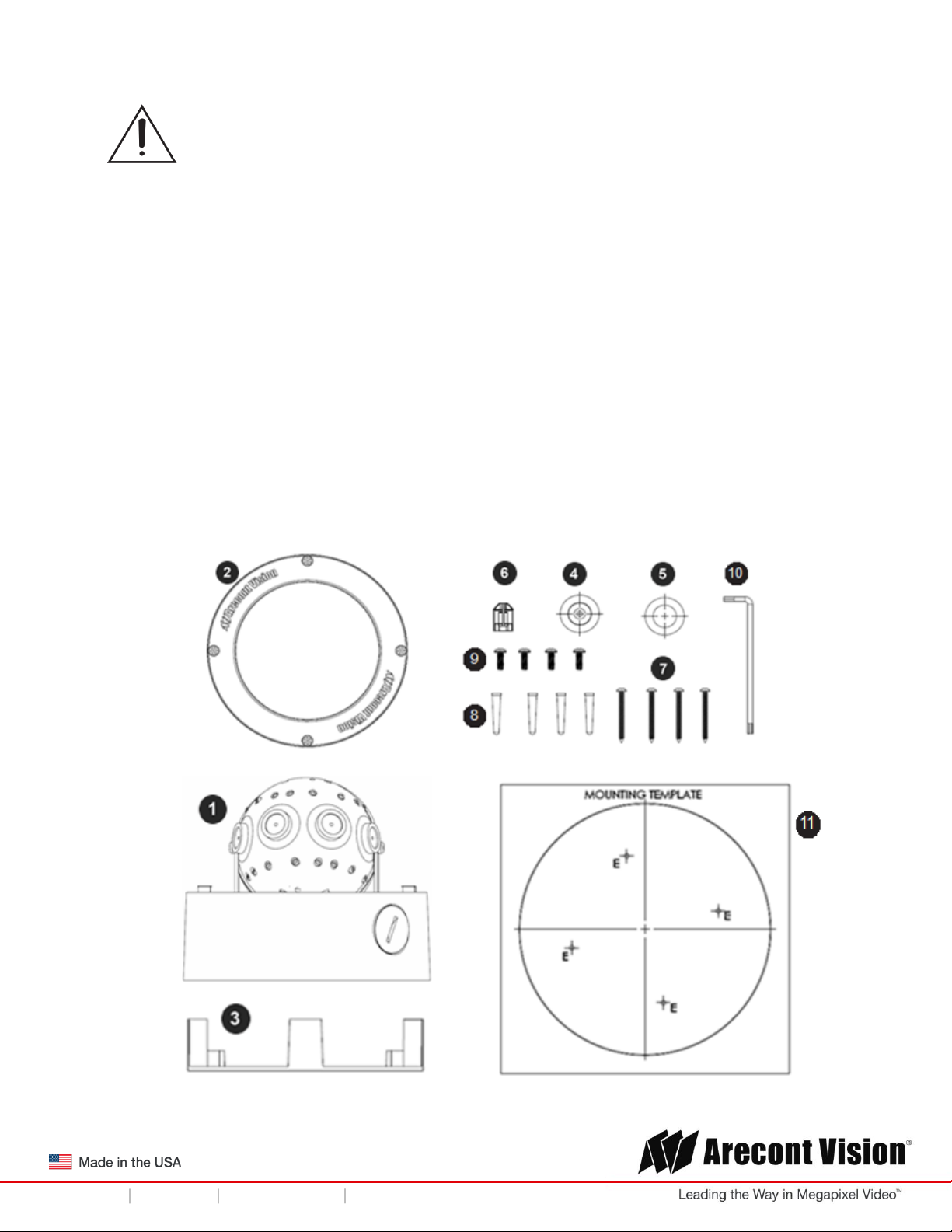
Package Contents
This equipment should be unpacked and handled with care. The original packaging is the safest
container in which to transport the unit and can be used if returning the unit for service. The packaging
contains:
Page | 3 support@arecontvision.com
+1.818.937.0700 877.CAMERA.8 www.arecontvision.com avsales@arecontvision.com
Page 4
Installation Manual
SurroundVideo® G5 Mini
Reference #
Description
1
1x Arecont Vision SurroundVideo G5 Mini® camera
2
1x Dome Cover
3
1x Mounting Plate
4
1x Grommet with Through Hole
5
1x Grommet without Through Hole
6
1x Insertion Tool
7
4x #6-32 1.0” Wood/ Metal Sheet Screw
8
4x #6-32 1.0” Drywall/ Masonry Mounting Anchors
9
4x #8-32 0.5” Machine Screw
10
1x Security L-key
11
1x Mounting Template
1x I/O cable
1x AC & DC auxiliary power cable
1x CD with Manual and Software
Page | 4 support@arecontvision.com
+1.818.937.0700 877.CAMERA.8 www.arecontvision.com avsales@arecontvision.com
Page 5

Installation Manual
SurroundVideo® G5 Mini
Warranty Information
Global (3 Year) Limited Warranty
ARECONT VISION warrants to Purchaser (and only Purchaser) (the “Limited Warranty”), that: (a) each
Product shall be free from material defects in material and workmanship for a period of thirty-six (36)
months from the date of shipment (the “Warranty Period”); (b) during the Warranty Period, the
Products will materially conform with the specification in the applicable documentation; (c) all licensed
programs accompanying the Product (the “Licensed Programs”) will materially conform with applicable
specifications. Notwithstanding the preceding provisions, ARECONT VISION shall have no obligation or
responsibility with respect to any Product that (i) has been modified or altered without ARECONT
VISION’s written authorization; (ii) has not been used in accordance with applicable documentation; (iii)
has been subjected to unusual stress, neglect, misuse, abuse, improper storage, testing or connection;
or unauthorized repair; or (iv) is no longer covered under the Warranty Period. ARECONT VISION
MAKE NO WARRANTIES OR CONDITIONS, EXPRESS, IMPLIED, STATUTORY OR OTHERWISE,
OTHER THAN THE EXPRESS LIMITED WARRANTIES MADE BY ARECONT VISION ABOVE, AND
ARECONT VISION HEREBY SPECIFICALLY DISCLAIMS ALL OTHER EXPRESS, STATUTORY AND
IMPLIED WARRANTIES AND CONDITIONS, INCLUDING THE IMPLIED WARRANTIES OF
MERCHANTABILITY, FITNESS FOR A PARTICULAR PURPOSE, NON-INFRINGEMENT AND THE
IMPLIED CONDITION OF SATISFACTORY QUALITY. ALL LICENSED PROGRAMS ARE LICENSED
ON AN “AS IS” BASIS WITHOUT WARRANTY. ARECONT VISION DOES NOT WARRANT THAT (I)
THE OPERATION OF THE PRODUCTS OR PARTS WILL BE UNINTERRUPTED OR ERROR FREE;
(II) THE PRODUCTS OR PARTS AND DOCUMENTATION WILL MEET THE END USERS’
REQUIREMENTS; (III) THE PRODUCTS OR PARTS WILL OPERATE IN COMBINATIONS AND
CONFIGURATIONS SELECTED BY THE END USER; OTHER THAN COMBINATIONS AND
CONFIGURATIONS WITH PARTS OR OTHER PRODUCTS AUTHORIZED BY ARECONT VISION
OR (IV) THAT ALL LICENSED PROGRAM ERRORS WILL BE CORRECTED.
For RMA and Advance Replacement information visit http://www.arecontvision.com
Page | 5 support@arecontvision.com
+1.818.937.0700 877.CAMERA.8 www.arecontvision.com avsales@arecontvision.com
Page 6

Installation Manual
SurroundVideo® G5 Mini
Camera Overview
The SurroundVideo® G5 Mini series network camera is a dual encoder (H.264 &MJPEG), 180 Degree
and/or 360 degree panoramic day/night IP camera available in 12MP Megapixel and 20 Megapixel
resolutions.. The SurroundVideo® G5 Mini series camera is a compliant Day/Night camera, featuring
PSIA compliance, privacy masking, extended motion detection and flexible cropping. This fully
compliant implementation of H.264 provides full 8192 x 1536 12 megapixel resolution at full video frame
rates of 10 frames per second (fps). At 20 megapixel resolution it provides 10240x1920 at full video
frame rate of 7 frames per second (fps). This camera is designed to provide in all in one solution with
four integrated 3/5 Megapixel sensors, IK-10 vandal resistant dome and housing, rated IP66 for water
and dust protection, to use camera for indoor and outdoor applications.
The SurroundVideo® G5 Mini Series is built with Arecont Vision’s proprietary massively-parallel
MegaVideo® technology, the SurroundVideo® G5 Mini Series has the ability to output multiple image
formats allowing simultaneous viewing of the full resolution field of view and regions of interest for high
definition forensic zooming. Binning technique improves low-light performance, increases sensitivity
and produces better SNR by combining and averaging pixels.
Page | 6 support@arecontvision.com
+1.818.937.0700 877.CAMERA.8 www.arecontvision.com avsales@arecontvision.com
Page 7
Installation Manual
SurroundVideo® G5 Mini
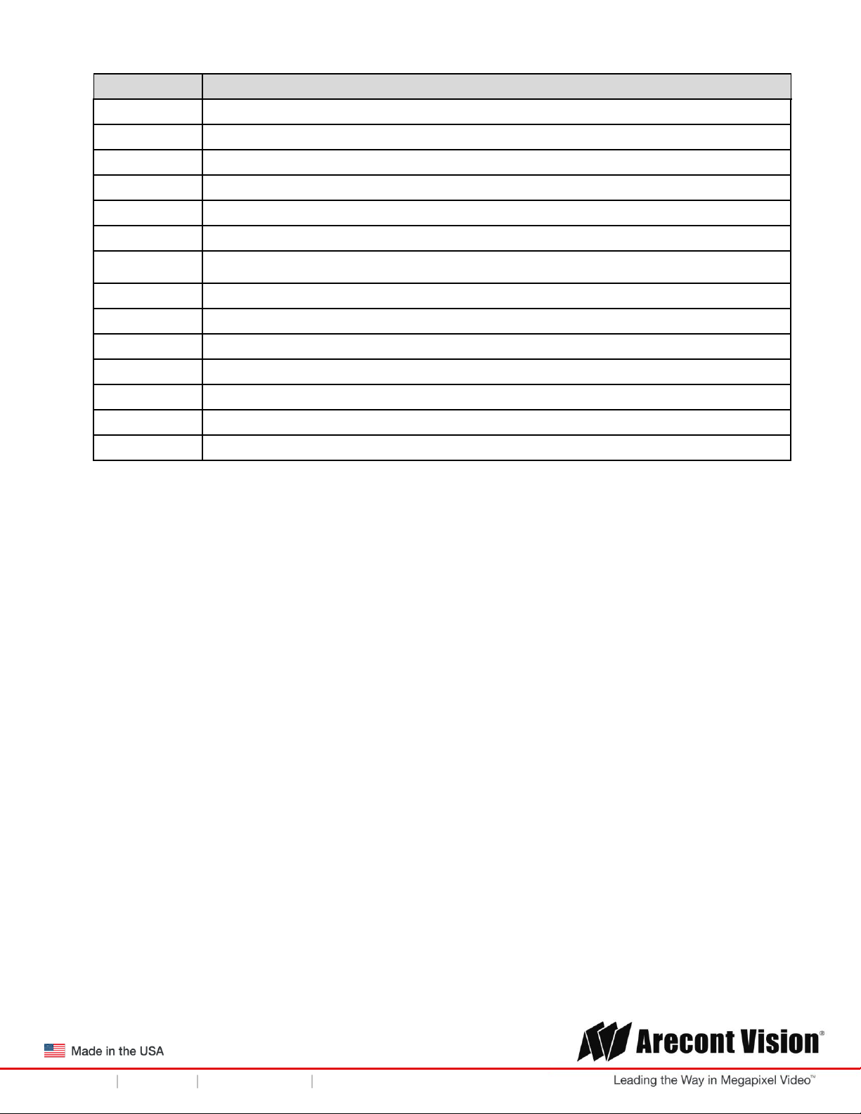
Installation
1. Determine a secure location to mount the camera.
2. Use the supplied security L-key, to loosen the four (4) screws securing the dome cover.
3. Remove the dome cover and protective foam. Do not remove screws from the dome cover.
The SurroundVideo® G5 Mini camera has been designed to provide installers with flexible
mounting options such as ceilings, walls, poles or corners.
NOTE: When mounting the camera outdoors or in a wet environment, use of supplied grommet
is recommended. Ensure the grommet properly seated flush with the camera housing.
Page | 7 support@arecontvision.com
+1.818.937.0700 877.CAMERA.8 www.arecontvision.com avsales@arecontvision.com
Page 8
Installation Manual
SurroundVideo® G5 Mini
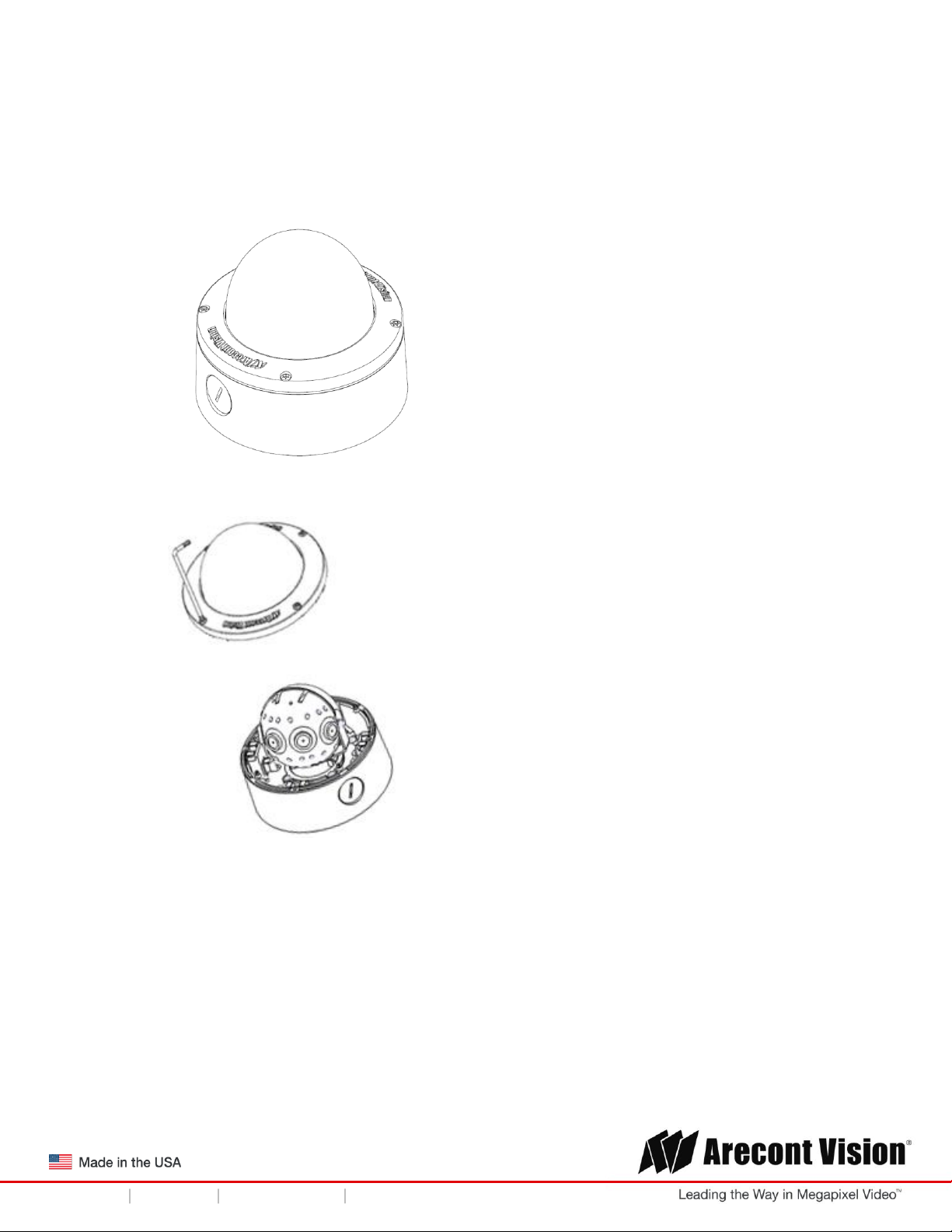
Reference #
Pendant Mount Components Required
1
Pendant mount (AV-PMJB) with integrated junction box
2
SurroundVideo® G5 Mini camera
3
MD-CAP mounting cap
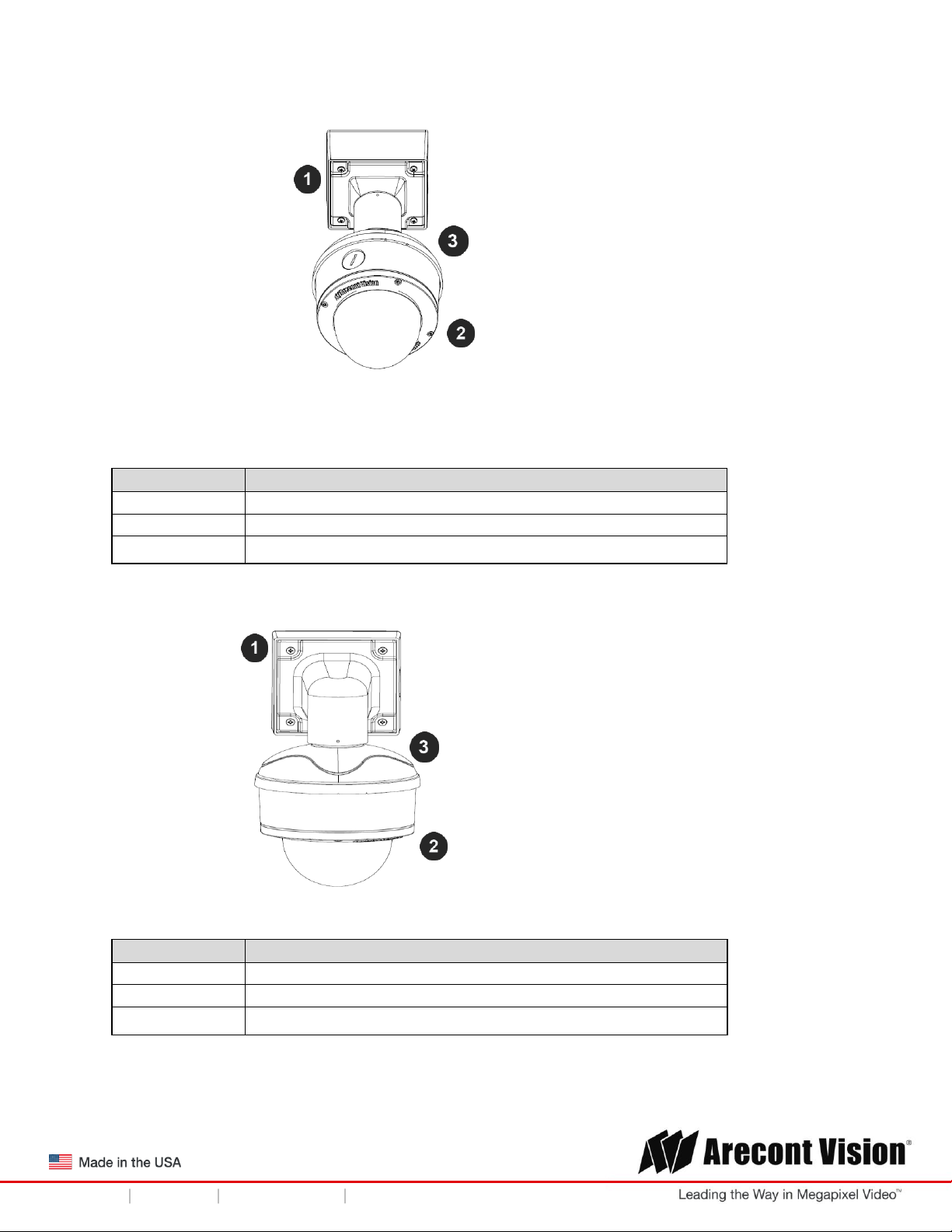
Reference #
Wall Mount Components Required
1
Wall mount (AV-WMJB) with integrated junction box
2
SurroundVideo® G5 Mini camera
3
MD-CAP mounting cap
Ensure you have the proper compatible mounting parts prior to starting your installation:
Pendant mount
Wall mount
Page | 8 support@arecontvision.com
+1.818.937.0700 877.CAMERA.8 www.arecontvision.com avsales@arecontvision.com
Page 9

Installation Manual
SurroundVideo® G5 Mini
Reference #
Pole Mount Components Required
1
Wall mount (AV-WMJB) with integrated junction box
2
MD-CAP mounting cap
3
SurroundVideo® G5 Mini camera
4
AV-PMA pole mount adapter
Reference #
Corner Mount Components Required
1
Wall mount (AV-WMJB) with integrated junction box
2
MD-CAP mounting cap
3
SurroundVideo® G5 Mini camera
4
AV-CRMA corner mount adapter
Pole mount
Corner mount
4. Use the Arecont Vision software AV IP Utility located on the CD or available for download at our
website (www.arecontvision.com) for camera discovery and setup (see Instruction Manual located on
the CD or available on our website).
Page | 9 support@arecontvision.com
+1.818.937.0700 877.CAMERA.8 www.arecontvision.com avsales@arecontvision.com
Page 10

Installation Manual
SurroundVideo® G5 Mini
Surface Mount
The SurroundVideo® G5 Mini camera can be directly attached onto hard ceilings or walls including
wood, plastic, metal and concrete.
1. Use the template, anchors, and screws provided to prepare the mounting provisions for the
camera installation.
2. Use the supplied security L-key, to loosen the four (4) tamper resistant screws securing the
dome cover as shown in Figure 1. Do not remove screws from the dome cover.
Figure 1
3. Remove the protective foam and discard.
4. Install four supplied dry wall anchors using the supplied mounting template.
5. Align four supplied screws with the dry wall anchors and screw mounting plate into place as
shown in Figure 2.
Figure 2
Page | 10 support@arecontvision.com
+1.818.937.0700 877.CAMERA.8 www.arecontvision.com avsales@arecontvision.com
Page 11
Installation Manual
SurroundVideo® G5 Mini
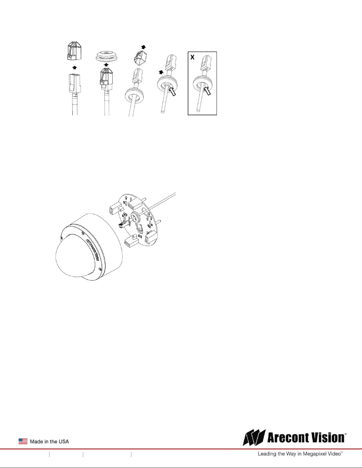
6. Prepare the network cable with the supplied grommet and insertion tool as shown in Figure 3.
Figure 3
NOTE: When mounting the camera outdoors or in a wet environment, use of supplied grommet
is recommended. Ensure the grommet is properly seated flush with the camera housing.
7. Align the hole on SurroundVideo® G5 Mini camera with the hole on mounting plate, and install
the grommet on camera housing as shown in Figure 4.
Figure 4
NOTE: If using the side connection of the NPT port, you need to install the supplied grommet
without a through hole on the camera housing, and remove the cap covering the side entrance,
otherwise; leave the cap in place. If using the NPT port, always use Teflon tape around the
threads to ensure proper sealing. The conduit fits ¾” NPT standard. Ensure NPT port is facing
downward.
Page | 11 support@arecontvision.com
+1.818.937.0700 877.CAMERA.8 www.arecontvision.com avsales@arecontvision.com
Page 12
Installation Manual
SurroundVideo® G5 Mini
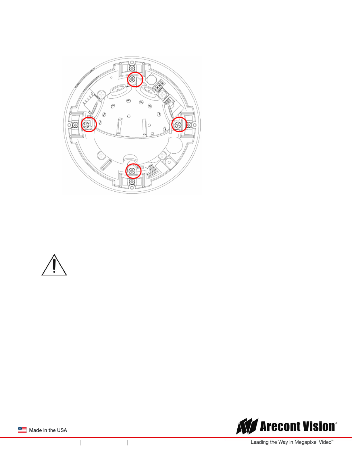
CAUTION! The captive screws must be used to properly secure the dome cover and
camera housing. Failure to use the captive fastener may result in serious injury. When
mounting the dome cover to the camera housing, ensure that the gasket is properly seated
and not folded. Failure to do so may result in water and dust ingress. Water damage from
improper installation is not covered by the warranty!
8. Fasten securely four captive screws as shown in Figure 5.
Figure 5
9. Attach the Dome Cover to the SurroundVideo® G5 Mini camera and fasten securely four
captive screws.
10. To configure the camera, reference the camera discovery, set-up and configuration section.
Page | 12 support@arecontvision.com
+1.818.937.0700 877.CAMERA.8 www.arecontvision.com avsales@arecontvision.com
Page 13

Installation Manual
SurroundVideo® G5 Mini
Wall Mount
For a proper wall mount installation, the AV-WMJB wall mount and MD-CAP wall mount cap are
required (sold separately). A wall mount should only be attached onto hard ceilings including
wood, plastic, metal, and concrete.
1. Using the Mounting template, prepare the mounting provisions for the camera installation.
2. Connect wall mount cap and wall mount as shown in Figure 1.
Figure 1: Attach wall mount cap to the wall mount
NOTE: The thread size for Top shield, pendant pole and mount is 1.5” NPT.
3. Attach the wall mount to the wall using the four drywall screws provided or any optional
hardware suitable for the mounting surface.
4. Run the Ethernet Cable and outside power cable (if necessary) through the supplied rubber
gasket and then through the wall mount. Ensure the gasket is seated properly.
5. Attach the mounting plate to the MD-CAP with the supplied screws as shown in Figure 2.
Figure 2
Page | 13 support@arecontvision.com
+1.818.937.0700 877.CAMERA.8 www.arecontvision.com avsales@arecontvision.com
Page 14

Installation Manual
SurroundVideo® G5 Mini
6. Prepare the network cable with the supplied grommet and insertion tool as shown in Figure 3.
Figure 3
NOTE: When mounting the camera outdoors or in a wet environment, use of supplied grommet
is recommended. Ensure the grommet is properly seated flush with the camera housing.
7. Align the hole on SurroundVideo® G5 Mini camera with the hole on mounting plate, and install
the grommet on camera housing as shown in Figure 4.
Figure 4
8. Fasten securely four captive screws as shown in Figure 5.
Figure 5
Page | 14 support@arecontvision.com
+1.818.937.0700 877.CAMERA.8 www.arecontvision.com avsales@arecontvision.com
Page 15

Installation Manual
SurroundVideo® G5 Mini
CAUTION! The captive screws must be used to properly secure the dome cover and
camera housing. Failure to use the captive fastener may result in serious injury. When
mounting the dome cover to the camera housing, ensure that the gasket is properly seated
and not folded. Failure to do so may result in water and dust ingress. Water damage from
improper installation is not covered by the warranty!
9. Attach the Dome Cover to the SurroundVideo® G5 Mini camera and fasten securely four captive
screws as shown in Figure 6.
Figure 6
10. To configure the camera, reference the camera discovery, set-up and configuration section.
Page | 15 support@arecontvision.com
+1.818.937.0700 877.CAMERA.8 www.arecontvision.com avsales@arecontvision.com
Page 16

Installation Manual
SurroundVideo® G5 Mini
Pendant Mount
For a proper pendant mount installation, the AV-PMJB pendant mount and MD-CAP mounting cap
are required (sold separately). A pendant mount should only be attached onto hard ceilings including
wood, plastic, metal, and concrete.
1. Using the mounting template, prepare the mounting provisions for the camera installation.
2. Connect top shield, pendant pole and mount together as shown in Figure 1.
Figure 1: Attach the mount cap and pendant mount
NOTE: The thread size of top shield, pendant pole and mount is 1.5” NPT.
3. Attach the pendant mount to the ceiling using the four wood screws provided or any optional
hardware suitable for the mounting surface.
4. Run the Ethernet Cable and outside power cable (if necessary) through the supplied rubber
gasket and then through the pendant. Ensure the gasket is seated properly.
5. Attach the mounting plate to the MD-CAP with the supplied screws as shown in Figure 2.
Figure 2
Page | 16 support@arecontvision.com
+1.818.937.0700 877.CAMERA.8 www.arecontvision.com avsales@arecontvision.com
Page 17

Installation Manual
SurroundVideo® G5 Mini
6. Prepare the network cable with the supplied grommet and insertion tool as shown in Figure 3.
Figure 3
NOTE: When mounting the camera outdoors or in a wet environment, use of supplied grommet
is recommended. Ensure the grommet is properly seated flush with the camera housing.
7. Align the hole on SurroundVideo® G5 Mini camera with the hole on mounting plate, and install
the grommet on camera housing as shown in Figure 4.
Figure 4
8. Fasten securely four captive screws as shown in Figure 5.
Figure 5
Page | 17 support@arecontvision.com
+1.818.937.0700 877.CAMERA.8 www.arecontvision.com avsales@arecontvision.com
Page 18

Installation Manual
SurroundVideo® G5 Mini
CAUTION! The captive screws must be used to properly secure the dome cover and
camera housing. Failure to use the captive fastener may result in serious injury. When
mounting the dome cover to the camera housing, ensure that the gasket is properly seated
and not folded. Failure to do so may result in water and dust ingress. Water damage from
improper installation is not covered by the warranty!
9. Attach the Dome Cover to the SurroundVideo® G5 Mini camera and fasten securely four
captive screws as shown in Figure 6.
Figure 6
10. To configure the camera, reference the camera discovery, set-up and configuration section.
Page | 18 support@arecontvision.com
+1.818.937.0700 877.CAMERA.8 www.arecontvision.com avsales@arecontvision.com
Page 19

Installation Manual
SurroundVideo® G5 Mini
+1.818.937.0700 877.CAMERA.8 www.arecontvision.com avsales@arecontvision.com
Reference #
Description
1
Remove conduit plug
2
Connect ¾” NPT conduit to junction box adapter
(ensure use of water seal tape)
Pole Mount
For a pole mount installation, the AV-WMJB wall mount, AV-PMA pole mount, and MD-CAP mount
cap are required (sold separately). A pole mount should only be attached onto hard ceilings
including wood, plastic, metal, and concrete.
1. Using the mounting template, prepare the mounting provisions for the camera installation.
2. Connect the wall mount cap and wall mount.
3. Attach the Junction Box Adapter to the Pole Mount Adapter as shown in Figure 1.
4. Remove the conduit plug on the junction box adapter and connect ¾” NPT conduit to the
junction box adapter (Figure 1).
Figure 1: Attach conduit to AV-JBA junction box adapter
NOTE: Use silicon or water pipe seal tape to make sure no water leakage between conduit
pipe and junction box adapter.
5. Run the Ethernet cable and outside power cable (if necessary) through the supplied rubber
gasket and then through the Junction Box Adapter and AV-WMJB, Wall Mount Adapter. Ensure
the gasket is seated properly.
6. Attach the Wall Mount Adapter (AV-WMJB) to the Pole Mount Adapter (AV-PMA) as shown in
Figure 2.
Page | 19 support@arecontvision.com
+1.818.937.0700 877.CAMERA.8 www.arecontvision.com avsales@arecontvision.com
Page 20

Installation Manual
SurroundVideo® G5 Mini
Reference #
Description
1
Steel straps with compression screws
2
AV-WMJB wall mount
3
MD-CAP mount cap
4
Conduit
5
AV-PMA pole mount
6
Apply Teflon water seal tape to the thread of ¾” NPT
pipe to avoid water leakage
CAUTION! The captive screws must be used to properly secure the dome cover and
camera housing. Failure to use the captive fastener may result in serious injury. When
mounting the dome cover to the camera housing, ensure that the gasket is properly seated
and not folded. Failure to do so may result in water and dust ingress. Water damage from
improper installation is not covered by the warranty!
Figure 2: Attach wall mount adapter to pole mount adapter
7. Use the supplied two Steel Straps to attach the Pole Mount Adapter to the pole and tighten the
compression screws as shown in Figure 2.
8. To attach the camera to the Wall Mount Adapter (AV-WMJB), reference the Installation and Wall
Mount section.
9. To configure the camera, reference the camera discovery, set-up and configuration section.
Page | 20 support@arecontvision.com
+1.818.937.0700 877.CAMERA.8 www.arecontvision.com avsales@arecontvision.com
Page 21

Installation Manual
SurroundVideo® G5 Mini
Reference #
Description
1
Remove conduit plug
2
Connect ¾” NPT conduit to junction box adapter
(ensure use of water seal tape)
Corner Mount
For a corner mount installation, the AV-WMJB wall mount, AV-CRMA corner mount, and MDCAP mount cap are required (sold separately). A corner mount should only be attached onto
hard corner surfaces including wood, plastic, metal, and concrete.
1. Using the Mounting template, prepare the mounting provisions for the camera installation.
2. Connect the wall mount cap and wall mount.
3. Attach the Junction Box Adapter to the Corner Mount Adapter as shown in Figure 1.
4. Remove the conduit plug on the junction box adapter and connect ¾” NPT conduit to the
junction box adapter as shown in Figure 1.
Figure 1: Attach conduit to SV-JBA junction box adapter
NOTE: Use silicon or water pipe seal tape to make sure no water leakage between conduit pipe
and junction box adapter.
5. Run the Ethernet cable and outside power cable (if necessary) through the supplied rubber
gasket and then through the Junction Box Adapter and AV-WMJB, Wall Mount Adapter. Ensure
the gasket is seated properly.
6. Attach the Wall Mount Adapter (AV-WMJB) to the Corner Mount Adapter (AV-CRMA) as shown
in Figure 2.
Page | 21 support@arecontvision.com
+1.818.937.0700 877.CAMERA.8 www.arecontvision.com avsales@arecontvision.com
Page 22

Installation Manual
SurroundVideo® G5 Mini
Reference #
Description
1
Attach corner mount adapter to exterior 90 corner wall
2
AV-WMJB wall mount
3
MD-CAP mount cap
4
Conduit
5
AV-CRMA corner mount adapter
6
Apply Teflon water seal tape to the thread of ¾” NPT
pipe to avoid water leakage
CAUTION! The captive screws must be used to properly secure the dome cover and
camera housing. Failure to use the captive fastener may result in serious injury. When
mounting the dome cover to the camera housing, ensure that the gasket is properly seated
and not folded. Failure to do so may result in water and dust ingress. Water damage from
improper installation is not covered by the warranty!
Figure 2: Attach corner mount adapter to exterior corner wall
7. Using the screws provided (or other hardware), attach the Corner Mount Adapter to an exterior
90 degree corner wall.
8. To attach the camera to the Wall Mount Adapter (AV-WMJB), reference the Installation and Wall
Mount section.
9. To configure the camera, reference the camera discovery, set-up and configuration section.
Page | 22 support@arecontvision.com
+1.818.937.0700 877.CAMERA.8 www.arecontvision.com avsales@arecontvision.com
Page 23

Installation Manual
SurroundVideo® G5 Mini
Electrical Box Adapter
The mounting plate is used to attach the camera to a common single, double or square electrical
box.
1. Using the supplied machine screws, match the mounting holes on the mounting plate with the
threaded holes on the electrical box. Ensure every threaded hole is matched with a mounting
hole.
2. Attach the mounting plate to the user supplied electrical box as shown in Figure 1.
Figure 1: Attach the mounting plate to common electrical box
Page | 23 support@arecontvision.com
+1.818.937.0700 877.CAMERA.8 www.arecontvision.com avsales@arecontvision.com
Page 24

Installation Manual
SurroundVideo® G5 Mini
Figure 1A: Recommended height for panoramic
Figure 1B: Less curvature provides better results
Figure 1C: Higher curvature produces less desirable
Mounting Recommendations
For the best visibility toward the target, and a minimal blind spot below the camera, Arecont Vision
recommends mounting panoramic cameras 15-20ft off the ground. If the application is unable to meet
this criteria, for every 10ft the camera is mounted from the ground, expect a 10ft blind spot below, and
the camera should be aimed ~100ft, for every 10ft mounted from the ground, toward the horizon.
For example, a camera mounted at 30ft will have a 30ft blind spot below the camera and should be
aimed 300ft toward the horizon. In the example below, the camera in Figures 1B and 1C are both
mounted 30ft high; however, the camera in Figure 1B is aimed 250ft toward the horizon and the camera
in Figure 1C is only aimed 150ft toward horizon. As a result, the camera in Figure 1C will have less
than desirable results due to its higher curvature.
Page | 24 support@arecontvision.com
+1.818.937.0700 877.CAMERA.8 www.arecontvision.com avsales@arecontvision.com
Page 25

Installation Manual
SurroundVideo® G5 Mini
Figure 1D: Mounting height of 8ft and aimed 80ft toward horizon
Figure 1E: Mounting height of 8ft and aimed only 30ft toward horizon
In the example below, the camera in Figures 1D and 1E are both mounted 8ft high; however, the
camera in Figure 1D is aimed 80ft toward the horizon and the camera in Figure 1E is only aimed at 30ft
toward horizon. The camera in Figure 1E results in a drastic curvature with less usable video.
Page | 25 support@arecontvision.com
+1.818.937.0700 877.CAMERA.8 www.arecontvision.com avsales@arecontvision.com
Page 26

Installation Manual
SurroundVideo® G5 Mini
Adjusting the Pan, Tilt and Focus
1. Remove the dome cover by loosening the captive fasteners with the supplied security L-key
screwdriver.
2. Power on the camera to adjust the pan, tilt and focus.
3. To adjust the gimbal tilt, use #2 Phillips screwdriver to loosen two Philips head screws on both
sides of the Gimbal, no more than two full turns. Adjust the pan and tilt to obtain the desired field
of view as shown in Figure 1. NOTE: Do not remove the screws!
180 configuration 360 Configuration
Figure 1: Loose camera head to adjust the field of view
4. To adjust each lens in the 360 configuration, loosen the two set screws on the top shell with a
#1 Phillips screwdriver. Adjust each lens angle tilt as required and tighten the two set screws
show in the image below.
Page | 26 support@arecontvision.com
+1.818.937.0700 877.CAMERA.8 www.arecontvision.com avsales@arecontvision.com
Page 27

Installation Manual
SurroundVideo® G5 Mini
5. To focus each of the four lenses, remove the lens cap and focus the lens by turning the lens
clockwise or counterclockwise as shown in the image below:
180 Configuration 360 Configuration
NOTE: The wave washer underneath the lens prevents it from losing focus in vibration.
1. Lock the camera head in place by fastening securely two Philips head screws on both sides of
the Gimbal as shown in Figure 2. NOTE: Do not over torque the screws.
Figure 2
.
Optional: Connecting Digital I/O
The auxiliary input and output are accessible after removing dome cover as shown in Figure 1.
Page | 27 support@arecontvision.com
+1.818.937.0700 877.CAMERA.8 www.arecontvision.com avsales@arecontvision.com
Page 28

Installation Manual
SurroundVideo® G5 Mini
Figure 1
To use digital I/O, connect digital I/O with pigtail cable connector as shown below.
NOTE: SurroundVideo® G5 Mini suppots digital input and digital output. See Table 1 for electrical
characteristics.
Page | 28 support@arecontvision.com
+1.818.937.0700 877.CAMERA.8 www.arecontvision.com avsales@arecontvision.com
Page 29

Installation Manual
SurroundVideo® G5 Mini
NOTE: The digital input is electrically isolated from the rest of the camera’s electrical circuity via
general-purpose photo couplers. The input is additionally protected with a serial 250 Ohm resistor, and
a de-bouncing circuit. Duration of any input signal should be at least 5 ms to comply with the
requirements of the de-bouncing circuit.
NOTE: Table 2 shows the cable color for digital input and ouput.
Page | 29 support@arecontvision.com
+1.818.937.0700 877.CAMERA.8 www.arecontvision.com avsales@arecontvision.com
Page 30

Installation Manual
SurroundVideo® G5 Mini
Reference #
Description
1
PoE Connector
Camera Power Up
This product should be installed by a qualified service technician in accordance with the
National Electrical Code (NEC 800 CEC Section 60) or applicable local code. Make sure
that your installation of wires complies with Electrical Code of the local government where
the camera is installed and no bare wires are exposed.
1. Connect the camera to a PoE port on 100Mbps network PoE switch using an Ethernet cable as
shown in the image below.
2. If the camera is powered by an outside power supply, 18~48VDC (green and brown wires) or
24VAC(red and black wires), connect the power cable.
CAUTION! Make the connections inside a watertight compartment. Isolate unused power
wires individually.
After connections are made, ensure that the watertight compartment is tightly closed and
cables and conduits are properly sealed to prevent ingress of water.
3. Connect the PoE switch to your computer’s network port using an Ethernet cable.
Page | 30 support@arecontvision.com
+1.818.937.0700 877.CAMERA.8 www.arecontvision.com avsales@arecontvision.com
Page 31

Installation Manual
SurroundVideo® G5 Mini
LED
Status
Description
Yellow
Flashing
Link has been established.
Solid
Normal Operation.
Green
Flashing
Camera has been accessed. Normal operation.
Solid
N/A
None
None
No Connection.
Auxiliary Power
If the camera is powered by a separate outside AC or DC power source, run the supplied power
cable through the access hole on the camera housing and connect the power cable to the 4position connector on the main camera board. The approximate location of the 4-position
connector is circled below.
NOTE: Cameras using auxiliary power with 802.1x enabled may need to manually power cycle the
camera to reconnect to the network.
CAUTION! Make the connections inside a watertight compartment. Isolate unused power
wires individually.
After connections are made, ensure that the watertight compartment is tightly closed and cables and
conduits are properly sealed to prevent ingress of water.
NOTE: A yellow LED on the rear of the camera illuminates after a few seconds.
The flashing yellow LED indicates that a link to your computer has been established.
A green LED will blink when the camera has been accessed.
Page | 31 support@arecontvision.com
+1.818.937.0700 877.CAMERA.8 www.arecontvision.com avsales@arecontvision.com
Page 32

Installation Manual
SurroundVideo® G5 Mini
NOTE: Wiring methods shall be in accordance with the National Electrical Code/NFPA 70/ANSI, and
with all local codes and authorities having jurisdiction. Wiring should be UL Listed and/or Recognized
wire suitable for the application.
Reset to Factory Default
1. You can reset to factory default via camera web interface or AV IP Utility. This can be done by
the following steps:
a. Open AV IP Utility and Click on Tools as seen in Figure 1.
Figure 1
b. Click on “Restore To Factory Default” as seen in Figure 2
Figure 2
NOTE: Additional information regarding the Arecont Vision® web interface is found separately in the AV
IP Utility Web Browser Manual via the Arecont Vision website.
Page | 32 support@arecontvision.com
+1.818.937.0700 877.CAMERA.8 www.arecontvision.com avsales@arecontvision.com
Page 33

Installation Manual
SurroundVideo® G5 Mini
Camera Discovery, Setup, and Configuration
For camera discovery and setup, the AV IP Utility is recommended. The software can be found on the
CD included with your camera or at: http://www.arecontvision.com/softwares.php.
The AV IP Utility has the ability to provide multiple discovery options, including broadcast and multicast,
check the status of a camera, change camera settings, import and export camera settings via a .csv
file, and update firmware and/or hardware from virtually anywhere with a network connection.
Whether used for large installations that require an update to multiple settings, or smaller installations
where only one camera needs changed, the AV IP Utility tool is efficient and convenient for mass or
single camera uploads.
The AV IP Utility tool is compatible with all Arecont Vision® megapixel cameras. The user manual for
the software is included on the CD that came with your camera or available on our website.
1.
Install the AV IP Utility Software as shown in Image 1. (Found on CD)
2.
Run the AV IP Utility Software by double clicking on the icon as shown in image 1. (Found on
your desktop)
Image 1
3. Click the Discovery Broadcast to display all Arecont Vision cameras on the network shown in
image 2. Duplicate IP Addresses typically indicate a conflict where one is left and one is
omitted; the AV UP Utility tool displays both.
Page | 33 support@arecontvision.com
+1.818.937.0700 877.CAMERA.8 www.arecontvision.com avsales@arecontvision.com
Image 2
Page 34

Installation Manual
SurroundVideo® G5 Mini
Network Protocols
The Arecont Vision SurroundVideo G5 mini cameras support RTSP, RTP/TCP, RTP/UDP, HTTP,
DHCP, TFTP, QoS, IP version 4 (IPv4), IP version 6 (IPv6), and 802.1x.
RTSP – Cameras communicate with video management systems over Real Time Streaming Protocol.
Do not change the RTSP port unless you are sure your VMS does not use the default setting.
RTP/TCP – The Real-time Protocol/Transmission Control Protocol is best suited for applications that
require high reliability, and transmission time is relatively less critical.
RTP/UDP – The Real-time Protocol/User Datagram Protocol is used for live unicast video, especially
when it is important to always have an up-to-date video stream, even if some images are dropped.
HTTP – The Hypertext Transfer Protocol is an application protocol for distributed, collaborative,
hypermedia information systems.
DHCP – The Dynamic Host Configuration Protocol allows network administrators to centrally manage
and automate the assignment of IP addresses. DHCP should only be enabled if using dynamic IP
address notification, or if the DHCP can update a DNS server.
TFTP – The Trivial File Transfer Protocol is a simple, lock-step, File Transfer Protocol which allows a
client to get from or put a file onto a remote host. TFTP lacks security and most of the advanced
features offered by more robust file transfer protocols such as File Transfer Protocol.
QoS – Quality of Service guarantees a certain level of a specified resource to selected traffic on a
network. A QoS-aware network prioritizes network traffic and provides a greater network reliability by
controlling the amount of bandwidth an application may use.
IPv4 – The SurroundVideo G5 Mini supports the IPv4 internet-layer protocol for packet-switched
internetworking across multiple IP networks. IPv4 uses 32-bit addressing which allows for devices and
users on the internet for routing traffic.
Page | 34 support@arecontvision.com
+1.818.937.0700 877.CAMERA.8 www.arecontvision.com avsales@arecontvision.com
Page 35

Installation Manual
SurroundVideo® G5 Mini
Image Equalization (Exposure Reference) Instructions
1. Launch the camera webpage
2. If the camera is a SurroundVideo G5 NON-WDR, skip to step 3 on the next page. For a
surroundVideo G5 WDR, Click “Setting” and select the desired channel to be the cameras
“Exposure Reference Channel” (see Image 5). Setting and Exposure Reference Channel will
reduce the color and brightness variations among channels.
Image 5
NOTE: The default setting for the “Exposure Reference Channel” is “Auto”, which means that each
channel is automatically adjusted to provide the best scene. This may cause variations from image to
image; however, the camera is providing the best image for each channel. When different channels are
under different lighting conditions, there will be some color or brightness variation among the channels.
See below for an example on how to adjust different reference channels to minimize brightness and
color differences.
NOTE: Using Exposure Reference Channel Setting may result in abnormal noise which can’t be
resolved!
- Exposure Reference Channel set as “Auto”
Page | 35 support@arecontvision.com
+1.818.937.0700 877.CAMERA.8 www.arecontvision.com avsales@arecontvision.com
Page 36

Installation Manual
SurroundVideo® G5 Mini
- Exposure Reference Channel set as Channel “1”
- Exposure Reference Channel set as Channel “2”
Equalize Brightness Instructions
NOTE: For a SurroundVideo G5 NON-WDR camera, once the camera webpage is launched, you must
make sure that “Equalize Brightness” function is on. You do this by :
3. Launch the camera webpage
4. Click “Settings” and make sure the check box for “Equalize Brightness” has been selected in
order to turn the function on. (Shown in Image 6 below)
Page | 36 support@arecontvision.com
+1.818.937.0700 877.CAMERA.8 www.arecontvision.com avsales@arecontvision.com
Page 37

Installation Manual
SurroundVideo® G5 Mini
Image 6
*Please note the difference between the “Equalize Brightness” function “ON” and “OFF” in the images
shown below:
- “Equalize Brightness” setting “OFF”
- “Equalize Brightness” setting “ON”
Page | 37 support@arecontvision.com
+1.818.937.0700 877.CAMERA.8 www.arecontvision.com avsales@arecontvision.com
Page 38

Installation Manual
SurroundVideo® G5 Mini
Administration and Password Setting
Administration is the place to set a password. Arecont Vision cameras support two levels of
password-protected access control. Camera authentication is compatible with RFC-2068 HTTP 1.1
and is supported by all standard browsers and video surveillance software.
A. There are two types of users with the following reserved names:
admin – full access to all camera settings and live video.
viewer –viewing access only to live video.
Setting and removing the passwords is the privilege of the admin user, while the viewer can only use
the existing password, but not change it. Factory defaults erase all current passwords for both the
admin and the viewer. A newly shipped camera has no password protection and allows full
anonymous access from the network. In case the admin password has not been set, the camera has
full anonymous access from the network, even if the viewer password has been set.
B. Access control setup consists of three steps:
1. Set admin password (using http commands or using the camera’s web page, see below).
2. Log-in using the admin password and set the viewer password.
3. Communicate the viewer password to the users.
NOTE: The Password accepts a 16 character ASCII but cannot contain white space or following
illegal symbols: # % & ` “ ‘ < >.
In order to delete viewer password, log-in as admin and change the viewer password to a reserved
password empty – this would restore the full anonymous access to the camera. The admin user can
change the viewer password at any time, even without knowing the current viewer password.
NOTE: If the admin password has been set and forgotten, it can only be erased by AV IP Utility
using key file. Please contact Arecont Vision technical support to obtain the key file required to
perform this function.
Page | 38 support@arecontvision.com
+1.818.937.0700 877.CAMERA.8 www.arecontvision.com avsales@arecontvision.com
Page 39

Installation Manual
SurroundVideo® G5 Mini
Mounting Templates
Unit: Inches
Page | 39 support@arecontvision.com
+1.818.937.0700 877.CAMERA.8 www.arecontvision.com avsales@arecontvision.com
Page 40

Installation Manual
SurroundVideo® G5 Mini
Support
1. Arecont Vision FAQ Page Located at ArecontVision.com
2. Check the following before you call:
Restore camera to factory default with AV200 or the camera webpage.
Upgrade to the latest firmware by visiting ArecontVision.com.
Isolate the camera on a dedicated network and test with AV200.
Swap the “troubled” camera with a known good camera to see if the problem follows the
camera or stays at the location.
3. Contact Arecont Vision Technical Support one of three ways:
1. Online Portal: Support.ArecontVision.com
2. Phone: 1.818.937.0700 (option #1)
3. Email: support@arecontvision.com
4. Use the Arecont Vision software AV IP Utility located on the CD or available for download at our
website (www.arecontvision.com) for camera discovery and setup (see Instruction Manual
located on the CD or available on our website).
Page | 40 support@arecontvision.com
+1.818.937.0700 877.CAMERA.8 www.arecontvision.com avsales@arecontvision.com
 Loading...