


 Loading...

This vehicle can be hazardous to operate.
A snowmobile is a very high performance vehicle. Because it does accelerate rapidly and is capable of very high speeds, it should not be operated by a novice or an inexperienced operator. Never accelerate rapidly or drive at high speed beyond the limits of visibility or without being totally familiar with the terrain and what lies in front of you. Obey speed limits and never operate at speeds that do not allow adequate maneuvering and stopping distances. Read and study the entire Operator’s Manual and Snowmobile Safety Handbook.
Failure to follow this warning could result in personal injury to yourself or others. For your safety, understand and follow all the warnings contained in this Operator’s Manual and on the labels on this vehicle.
Keep this Operator’s Manual with this vehicle at all times. If you lose your manual, contact your authorized dealer for a free replacement. The labels should be considered permanent parts of the vehicle. If a label comes off or becomes hard to read, contact your authorized dealer for a free replacement. Contact Arctic Cat Service Department, P.O. Box 810, Thief River Falls, MN 56701, for proper registration information.
FAILURE TO FOLLOW THE WARNINGS CONTAINED IN THIS MANUAL CAN RESULT IN SERIOUS INJURY OR DEATH.
The Operator’s Manual, Snowmobile Safety Handbook, and Snowmobile Decals display important information:
!
! WARNING
CAUTION
NOTE:
The Safety Alert Symbol means ATTENTION! BE ALERT! YOUR SAFETY IS INVOLVED.
WARNING identifies personal safety-related information. Follow the directive because it deals with the possibility of serious personal injury or even death.
CAUTION, without the safety alert symbol, identifies unsafe practices which may result in snowmobile-related damage. Follow the directive because it deals with the possibility of damaging part or parts of the snowmobile.
A NOTE identifies supplementary information worthy of particular attention.
Personal Injury
•To avoid injury to yourself and others, NEVER operate the snowmobile without first reading and understanding this manual and the Snowmobile Safety Handbook; then follow the instructions and heed the warnings given.
•USE COMMON SENSE.
•DON’T DRINK and DRIVE.
•STAY IN CONTROL at ALL TIMES.
•TELL YOUR FRIENDS. If you see a friend operating a snowmobile recklessly, at excessive speeds, while intoxicated, or in other unsafe ways, don’t wait until it is too late to warn of the consequences of snowmobile misuse. Such conduct endangers everyone. TAKE AN ACTIVE ROLE IN THE SAFETY OF YOURSELF AND OTHERS.
California Proposition 65
! WARNING
The Engine Exhaust from this product contains chemicals known to the State of California to cause cancer, birth defects or other reproductive harm.

Limited Warranty
Arctic Cat Inc. (hereinafter referred to as Arctic Cat) extends a limited warranty as described below on each new Arctic Cat Snowmobile it assembles and on each genuine Arctic Cat Snowmobile part and accessory assembled and sold by an authorized Arctic Cat Snowmobile dealer. The limited warranty on an Arctic Cat Snowmobile is extended to the original retail purchaser for the time periods described below; however, the balance of the remaining warranty may be transferred to another party unless the purchase is for commercial use (see below). Warranty coverage is only available in the country in which the original retail purchase occurs to the original retail purchaser resident in that country or to a transferee resident in that country of the balance of the remaining warranty.
Arctic Cat warrants only the products it assembles and/or sells and does not warrant that other products will function properly when used with an Arctic Cat Snowmobile or will not damage the Arctic Cat Snowmobile. Arctic Cat does not assume any liability for incidental or consequential damages.
Arctic Cat will repair or replace, at its option, free of charge (including any related labor charges), any parts that are found to be warrantable in material or workmanship. This repair work MUST be done by an authorized Arctic Cat Snowmobile dealer. No transportation charges, rental charges, or inconvenience costs will be paid by Arctic Cat. The warranty is validated upon examination of said parts by Arctic Cat or an authorized Arctic Cat Snowmobile dealer. Arctic Cat reserves the right to inspect such parts at its factory for final determination if warranty should apply.
The warranty periods are as follows:
1.For snowmobiles used for recreational purposes:
—If purchased between May 1 and November 30, warranty expires ONE (1) YEAR from December 1 of the current year. —If purchased between December 1 and April 30, ONE (1) YEAR from the date of sale.
2.For snowmobiles used for commercial purposes (including rental operations), ONE (1) YEAR from the date of invoice and/or 5000 MILES whichever comes first (non-transferable).
3.THIRTY (30) DAYS from date of sale of snowmobile on Arctic Cat supplied batteries.
Exclusions to this warranty include normal wear, abuse (i.e. a track run on marginal snow conditions without proper lubrication or additional idler wheels), and the following parts:
Fuel Filter |
Light Bulbs |
Windshield |
Drive Belt |
Torn or Punctured Upholstery |
Wear Bars |
Brake Pads |
Spark Plugs |
Drive Clutch/Driven Clutch Wear Parts |
|
Wear Strips |
Shock Absorber(s) - Standard* |
Shock Absorber(s) - Rebuildable** |
||
* Limited to one (1) year or 1000 miles of “normal” riding conditions - replace for defective or leaking shock, corroded or pitted shaft, peeling chrome.
**Limited to one (1) year or 1000 miles of “normal” riding conditions - rebuild for leaking shock (warranted) - replace for defective shock, corroded or pitted shaft, peeling chrome.
The following will VOID Arctic Cat’s warranty:
1.Failure to perform the proper break-in procedure and all related maintenance, storage procedures (if stored for extended periods), and/or service as recommended in the Operator’s Manual.
2.Repairs and/or adjustments by anyone other than an authorized Arctic Cat Snowmobile dealer.
3.Use of an improper fuel mixture ratio.
4.Use of improper gasoline, lubricating oils, or spark plugs.
5.An accident or subjecting the snowmobile to misuse, abuse, or negligent operation.
6.Any modification, addition, or removal of parts unless instructed to do so by Arctic Cat.
7.Use of the snowmobile in any way for racing purposes.
8.Removal of the engine for use in another vehicle.
9.Removal or mutilation of the Vehicle Identification Number or Engine Serial Number.
10.Use of parts not sold or approved by Arctic Cat.
11.Track and tunnel damage resulting from either ice stud or hooker plate installation.
12.Damage due to improper transportation.
Arctic Cat shall not be responsible for and this limited warranty excludes recovery of economic, punitive, consequential and incidental damages, lost profits, and loss of use. Some states or provinces do not allow the exclusion or limitation of incidental or consequential damages, so the above limitation may not apply to you. Arctic Cat’s aggregate liability may not exceed the price of the product. The law of the State of Minnesota shall apply to all claims or disputes, exclusive of its conflicts of law provisions.
IMPLIED WARRANTY EXCLUSION AND DISCLAIMER
To the fullest extent permitted by law, Arctic Cat excludes and disclaims all implied warranties of merchantability and fitness for a particular purpose.
If you are not satisfied with warranty service or repairs, you should contact Arctic Cat at (U.S.) 218-681-9851 or (Canada) 204-982-1656.
If the snowmobile is purchased through the Team Arctic Race Department Racing Program, there is no warranty.

Foreword
Congratulations! You have chosen a quality Arctic Cat Snowmobile designed and manufactured to give dependable service. Be sure, as the owner/operator of an Arctic Cat Snowmobile, to become thoroughly familiar with its basic operation, maintenance, and off-season storage procedures. Read this manual and the accompanying Snowmobile Safety Handbook before operating the snowmobile to ensure safe and proper use of your new Arctic Cat Snowmobile. Always operate the snowmobile within your level of skill and current terrain conditions.
This manual covers operator-related maintenance, operating instructions, and off-season storage instructions. If major repair or service is ever required, contact an authorized Arctic Cat Snowmobile dealer for professional service.
At the time of publication, all information and illustrations were technically correct. Some illustrations used in this manual are used for clarity purposes only and are not designed to depict actual conditions. Because Arctic Cat Inc. constantly refines and improves its products, no retroactive obligation is incurred.
This Operator’s Manual should be considered a permanent part of the snowmobile and must remain with the snowmobile at the time of resale. If the snowmobile changes ownership more than once, contact Arctic Cat Inc., Service Department, P.O. Box 810, Thief River Falls, MN 56701, for proper registration information.
Every Arctic Cat Snowmobile meets or exceeds the standards of the Snowmobile Safety and Certification Committee and displays the SSCC decal. Arctic Cat endorses and encourages the safe use of all snowmobiles. Always wear a helmet and eye protection. Drive with caution, observe all state and local regulations, and respect the rights of others. ISMA members like Arctic Cat do their part to improve trails, sponsor events, and generally support the sport of snowmobiling. As a member of the National Snowmobile Foundation, Arctic Cat Inc. promotes snowmobiling through education, charity, and research programs.
© 2018 Arctic Cat Inc.
Printed in U.S.A. October 2018

PARTS AND ACCESSORIES
When in need of replacement parts, oil, or accessories for your Arctic Cat Snowmobile, be sure to only use GENUINE ARCTIC CAT PARTS, OIL, AND ACCESSORIES. Only genuine Arctic Cat parts, oil, and accessories are engineered to meet the standards and requirements of your Arctic Cat Snowmobile. For a complete list of accessories, refer to the current Arctic Cat Accessory Catalog.
To aid in service and maintenance procedures on this snowmobile, an Illustrated Parts Manual is available through your local Arctic Cat Snowmobile dealer.
Reference Information
The Arctic Cat Snowmobile has two important identification numbers. The Vehicle Identification Number (VIN) is stamped on the side of the tunnel. The Engine Serial Number (ESN) is stamped into the crankcase of the engine.
These numbers are required by the dealer to properly complete warranty claims. No warranty will be allowed by Arctic Cat Inc. if the engine serial number or VIN is removed or mutilated in any way.
Always provide the snowmobile name, VIN, and ESN when contacting an authorized Arctic Cat Snowmobile dealer for parts, service, accessories, or warranty. If the complete engine must be replaced, ask the dealer to notify Arctic Cat for correct registration information.
Write the appropriate information for your Arctic Cat Snowmobile in the spaces below. Always use these numbers when referring to your snowmobile.
Model: ____________________________________
Date of Purchase: ____________________________
VIN (Vehicle Identification Number): ____________
ESN (Engine Serial Number):___________________
Your Arctic Cat Dealer: ______________________
Address: ___________________________________
Phone: ____________________________________

Table of Contents |
|
|
Specifications/Charts/Patterns/Diagrams ............. |
3-23 |
|
Specifications.......................................................... |
|
3 |
Torque Specifications ............................................. |
|
4 |
Torque Conversions (ft-lb/N-m) .............................. |
|
4 |
Tightening Torque (General Bolts) ......................... |
5 |
|
Crankshaft Runout/Repair Specifications ............... |
5 |
|
Arctic Power Valve (APV) System Specifications... 5 |
||
Electrical Specifications .......................................... |
|
5 |
Component Voltage/Resistance Chart — Water |
|
|
Temperature ........................................................ |
|
6 |
R-XC Team Drive Clutch Optional Components |
.... 7 |
|
R-SX Arctic Cat Drive Clutch/Driven Clutch Optional |
||
Components ........................................................ |
|
7 |
R-SX Arctic Cat Drive Clutch Cam Arms (w/Set |
|
|
Screw) ................................................................. |
|
8 |
Chain Case Performance Calibrations ................... |
9 |
|
Chains and Sprockets........................................... |
|
11 |
Rear Spring Selection........................................... |
|
11 |
Installed Spring Rate Chart................................... |
|
11 |
Front Suspension Sway Bar ................................. |
|
11 |
Rebuildable Shock Tools Required ...................... |
12 |
|
Optional Front Arm Shock Springs — R-XC......... |
12 |
|
Optional Dual Rate Spring Chart (DSR) ............... |
12 |
|
Rebuildable Shock Accessory Part Numbers ....... |
15 |
|
Fraction/Decimal Conversion Chart...................... |
16 |
|
Drill Bit Sizes (Number) Chart............................... |
|
16 |
Conversion Chart (mm/in.)................................... |
|
17 |
Wiring Diagram — Hood Harness (R-XC) ............ |
19 |
|
Wiring Diagram — Ignition/Main Harness (R-XC) 21 |
||
Wiring Diagram — Ignition/Main Harness (R-SX). 23 |
||
Setup Instructions ............................................... |
25-32 |
|
Removing Snowmobile from Crate/Installing |
|
|
Handlebar Assembly ......................................... |
|
25 |
Installing Windshield ............................................ |
|
25 |
Installing Front Shock Absorbers.......................... |
25 |
|
Installing Skis (R-SX)............................................ |
|
25 |
Installing Skis (R-XC)............................................ |
|
26 |
Sway Bar .............................................................. |
|
26 |
Brake System ....................................................... |
|
26 |
Ski Alignment........................................................ |
|
27 |
Recommended Gasoline ...................................... |
|
28 |
Preoperation Checks ............................................ |
|
29 |
Checking Headlight Aim ....................................... |
|
29 |
Track Tension/Track Alignment |
(R-SX) ............... |
29 |
Track Tension (R-XC)........................................... |
|
31 |
Track Alignment (R-XC)........................................ |
|
31 |
Test Ride .............................................................. |
|
32 |
General Information ............................................ |
33-37 |
R-SX Control Locations ........................................ |
33 |
R-XC Control Locations ........................................ |
33 |
Deluxe Digital Gauge (R-XC)................................ |
33 |
Power Sports Gauge (R-SX)................................. |
34 |
ACT Hot Start System (R-SX)............................... |
34 |
Diagnostic Codes.................................................. |
35 |
Arctic Power Valve (APV) System ........................ |
35 |
Exhaust Controlled Timing (ECT) System ............ |
36 |
Handlebar Tilt........................................................ |
36 |
Exhaust System .................................................... |
36 |
Liquid Cooling System .......................................... |
37 |
Drive Clutch and Driven Clutch............................. |
37 |
Drive Clutch/Driven Clutch Alignment................... |
37 |
Shock Absorbers................................................... |
37 |
Track Studs........................................................... |
37 |
Towing .................................................................. |
37 |
Operating Instructions ......................................... |
38-39 |
Starting and Stopping Engine ............................... |
38 |
Braking.................................................................. |
38 |
Emergency Stopping............................................. |
39 |
Lubrication................................................................ |
40 |
Chain Case ........................................................... |
40 |
Rear Suspension .................................................. |
40 |
Maintenance........................................................ |
41-76 |
Periodic Maintenance Checklist............................ |
41 |
Pre-Race/Practice Checklist ................................. |
42 |
Engine................................................................... |
42 |
Track Drive............................................................ |
61 |
Drive Sprockets..................................................... |
62 |
Brake System........................................................ |
63 |
Brake Fluid............................................................ |
63 |
Checking Brake Lever Travel................................ |
64 |
Bleeding Brake System......................................... |
64 |
Checking/Changing Brake Pads ........................... |
65 |
Drive Belt .............................................................. |
65 |
Driven Clutch ........................................................ |
69 |
Lights .................................................................... |
75 |
Ski Wear Bar......................................................... |
75 |
Rail Wear Strip...................................................... |
76 |
Performance Tips..................................................... |
77 |
Genuine Arctic Cat Products.................................... |
77 |
Preparation for Storage............................................ |
78 |
Preparation after Storage......................................... |
79 |
Special Tools....................................................... |
80-89 |
Declaration of Conformity......................................... |
90 |
2

Specifications
ENGINE
|
ZR 6000R-XC |
ZR 6000R-SX |
|
|
|
Engine Number |
0962-079 |
0962-073 |
|
|
|
Bore x Stroke |
73.8 x 70 mm (2.906 x 2.756 in.) |
73.8 x 70 mm (2.906 x 2.756 in.) |
|
|
|
Displacement |
599 cc (36.55 cu in.) |
599 cc (36.55 cu in.) |
|
|
|
Compression Ratio |
6.62:1 |
6.8:1 |
|
|
|
Cooling System |
Liquid |
Liquid |
|
|
|
Ignition Timing (Engine Warm) |
16.5° @ 2000 RPM 0.072” |
16.5° @ 2000 RPM 0.072” |
|
|
|
Spark Plug |
NGK BPR9ES |
NGK BPR9ES |
|
|
|
Spark Plug Gap |
0.0276-0.0307 in. |
0.0276-0.0307 in. |
|
|
|
Piston Skirt/Cylinder Clearance |
0.0030-0.0039 in. |
0.0030-0.0039 in. |
|
|
|
Piston Ring End Gap |
0.0118-0.0177 in. |
0.0118-0.0177 in. |
|
|
|
Cylinder Trueness Limit |
0.0019 in. |
0.0019 in. |
|
|
|
Piston Pin Diameter |
0.7872-0.7874 in. |
0.7872-0.7874 in. |
|
|
|
Piston Pin Bore Diameter |
0.7875-0.7877 in. |
0.7875-0.7877 in. |
|
|
|
Connecting Rod Small End Bore |
0.9844-0.9847 in. |
0.9844-0.9847 in. |
|
|
|
Connecting Rod Radial Play |
0.0005-0.0015 in. |
0.0005-0.0015 in. |
|
|
|
Crankshaft Runout (t.i.r) |
0.0000-0.0079 in. |
0.0000-0.0079 in. |
|
|
|
|
DRIVE |
|
|
|
|
Track Width |
38 cm (15 in.) |
38 cm (15 in.) |
|
|
|
Track Length (Overall) |
328 cm (129 in.) |
345 cm (136 in.) |
|
|
|
Track Lug Height |
31.8 mm (1.25 in.) |
44.5 mm (1.75 in.) |
|
|
|
Track Deflection (Tension) |
2 in. @ 20 lb |
2 in. @ 20 lb |
|
|
|
Drive Clutch Spring |
120/265 lb (p/n 0646-473) |
170/330 lb (p/n 0646-216) |
|
|
|
Cam Arms |
J14-66 (p/n 0646-869) |
60 Gram (p/n 0646-830) |
|
|
|
Driven Clutch Spring |
155/222 lb (p/n 0648-953) |
180/280 lb (p/n 0648-792) |
|
|
|
Torque Bracket |
38 ER/40S ER (p/n 0648-951) |
70-44-32 (p/n 0648-823) |
|
|
|
Top Gear |
23T (p/n 2602-967) |
20T (p/n 3602-169) |
|
|
|
Bottom Gear |
40T (p/n 1702-402) |
49T (p/n 1702-403) |
|
|
|
Chain |
86P (p/n 2602-743) |
90P (p/n 2602-760) |
|
|
|
|
CHASSIS |
|
|
|
|
Length (Overall) |
307.3 cm (121 in.) |
315 cm (124.25 in.) |
|
|
|
Height (Overall) |
116.2 cm (45.75 in.) |
113.06 cm (44.5 in.) |
|
|
|
Width (Overall) |
121.2 cm (47.75 in.) |
127.6 cm (50.25 in.) |
|
|
|
Ski Center-to-Center Distance |
110.5 cm (43.5 in.) |
106-109 cm (41.9-42.9 in.) |
|
|
|
Dry Weight (approx) |
215.9 kg (476 lb) |
205 kg (452 lb) |
|
|
|
|
MISCELLANEOUS |
|
|
|
|
Gas Tank Capacity (Rated) |
40.01 l (10.56 U.S. gallon) |
10.2 l (2.7 U.S. gallon) |
|
|
|
Chain Case Lubricant Capacity |
355 ml (12 fl oz) |
355 ml (12 fl oz) |
|
|
|
Injection Oil Reservoir Capacity |
3.04 l (3.6 U.S. qt) |
Premix (40:1 ratio) |
|
|
|
Cooling System Capacity |
5.71 l (6.0 U.S. qt) |
3.8 l (4.0 U.S. qt) |
|
|
|
Gasoline (Recommended) |
91 Octane Unleaded |
91 Octane (non-oxygenated) Minimum |
|
|
|
Engine Oil |
Arctic Cat Synthetic C-TEC2 |
Arctic Cat Synthetic C-TEC2 |
|
|
|
Chain Case Lubricant |
Arctic Cat Synthetic Chain Lube |
Arctic Cat Synthetic Chain Lube |
|
|
|
Suspension Grease |
Low-Temperature |
Low-Temperature |
|
|
|
Brake Fluid |
High-Temp DOT 4 |
High-Temp DOT 4 |
|
|
|
Drive Belt Part Number |
0627-107 |
0627-120 |
|
|
|
Drive Belt Projected width |
38.3 mm (1.507 in.) |
37.2 mm (1.464 in.) |
|
|
|
Drive Belt Circumference |
123.0 cm (48.425 in.) |
122.3 ± .457 cm (48.150 ± .180 in.) |
|
|
|
Headlight Bulb Part Number |
LED |
0609-956 |
|
|
|
3

Torque Specifications
NOTE: Torque specifications have the following tolerances:
Torque (ft-lb) |
Tolerance |
0-15 |
±20% |
16-39 |
±15% |
40+ |
±10% |
DRIVE SYSTEM
Item |
Secured to |
Torque |
|
ft-lb |
|||
|
|
||
Drive Clutch |
Engine |
51 |
|
|
|
|
|
Drive Clutch Cover |
Movable Sheave |
120 in.-lb |
|
Cam Arm Pin Lock Nut (SX) |
Cam Arm Pin |
11 |
|
Cam Arm Lock Nut (XC) |
Cam Arm Screw |
50 in.-lb |
|
|
|
|
|
Cam Arm Set Screw (SX) |
Cam Arm |
19 in.-lb |
|
|
|
|
|
Movable Sheave* |
Torque Bracket |
120 in.-lb |
|
Chain Case (Cap Screw) |
Chassis |
96 in.-lb |
|
|
|
|
|
Chain Case (Torx-Head Screw) |
Chassis |
12 |
|
Chain Case Cover |
Chain Case |
12 |
|
Brake Caliper |
Chassis |
25 |
|
|
|
|
|
Outside Caliper Housing |
Inside Caliper Housing |
25 |
|
|
|
|
|
Brake Line |
Caliper |
25 |
|
Brake Line |
Master Cylinder |
25 |
|
|
|
|
|
Brake Caliper |
Shield Cover |
96 in.-lb |
|
STEERING/FRONT |
SUSPENSION/CHASSIS |
|
|
|
|
|
|
Item |
Secured to |
Torque |
|
ft-lb |
|||
|
|
||
|
|
|
|
Ski |
Spindle |
35 |
|
Ski |
Wearbar |
8 |
|
|
|
|
|
Ski |
Ski Handle |
54 in.-lb |
|
|
|
|
|
Handlebar Adjuster |
Post |
15 |
|
Steering Support |
Mounting Block |
8 |
|
|
|
|
|
Steering Tie Rod Link |
Steering Post |
35 |
|
Steering Tie Rod Link |
Steering Arm |
20 |
|
Steering Post Cap |
Riser Block |
15 |
|
|
|
|
|
Steering Post |
Chassis |
55 |
|
|
|
|
|
Steering Tie Rod |
Steering Arm |
20 |
|
Tie Rod |
Spindle Arm |
32 |
|
|
|
|
|
Steering Support |
Spar |
20 |
|
Steering Support |
Upper Console |
30 in.-lb |
|
Steering Arm |
Chassis |
8 |
|
|
|
|
|
A-Arm (Upper) |
Chassis |
23 |
|
|
|
|
|
A-Arm (Lower) |
Chassis (Front) |
65 |
|
A-Arm (Lower) |
Chassis (Rear) |
45 |
|
|
|
|
|
A-Arm |
Spindle |
45 |
|
Shock Absorber |
Spindle |
45 |
|
Shock Absorber |
Chassis |
45 |
|
|
|
|
|
Sway Bar Link |
A-Arm/Sway Bar Link |
23 |
|
|
|
|
|
Sway Bar Mounting Bracket |
Chassis |
9 |
REAR SUSPENSION
Item |
Secured to |
Torque |
|
ft-lb |
|||
|
|
||
Wear Strip |
Rail |
50 in.-lb |
|
|
|
|
|
End Cap |
Rail |
80 in.-lb |
|
|
|
|
|
Mounting Block |
Rail |
20 |
|
Rear Arm |
Rail |
45 |
|
|
|
|
|
Rear Arm |
Idler Arm |
55 |
|
Spring Slide |
Rail |
20 |
|
Front Arm |
Rail |
52 |
|
|
|
|
|
Coupler Block Axle |
Rail |
40 |
|
|
|
|
|
Limiter Strap |
Rail Support |
72 in.-lb |
|
Skid Frame |
Tunnel |
55** |
|
|
|
|
|
Front Shock |
Rail |
50 |
|
Rail Support |
Rail |
20 |
|
Limiter Strap |
Front Arm |
72 in.-lb |
|
|
|
|
* w/Green Loctite #609 ** w/Blue Loctite #243
Torque Conversions
(ft-lb/N-m)
ft-lb |
N-m |
ft-lb |
N-m |
ft-lb |
N-m |
ft-lb |
N-m |
1 |
1.4 |
26 |
35.4 |
51 |
69.4 |
76 |
103.4 |
2 |
2.7 |
27 |
36.7 |
52 |
70.7 |
77 |
104.7 |
3 |
4.1 |
28 |
38.1 |
53 |
72.1 |
78 |
106.1 |
4 |
5.4 |
29 |
39.4 |
54 |
73.4 |
79 |
107.4 |
5 |
6.8 |
30 |
40.8 |
55 |
74.8 |
80 |
108.8 |
6 |
8.2 |
31 |
42.2 |
56 |
76.2 |
81 |
110.2 |
7 |
9.5 |
32 |
43.5 |
57 |
77.5 |
82 |
111.5 |
8 |
10.9 |
33 |
44.9 |
58 |
78.9 |
83 |
112.9 |
9 |
12.2 |
34 |
46.2 |
59 |
80.2 |
84 |
114.2 |
10 |
13.6 |
35 |
47.6 |
60 |
81.6 |
85 |
115.6 |
11 |
15 |
36 |
49 |
61 |
83 |
86 |
117 |
12 |
16.3 |
37 |
50.3 |
62 |
84.3 |
87 |
118.3 |
13 |
17.7 |
38 |
51.7 |
63 |
85.7 |
88 |
119.7 |
14 |
19 |
39 |
53 |
64 |
87 |
89 |
121 |
15 |
20.4 |
40 |
54.4 |
65 |
88.4 |
90 |
122.4 |
16 |
21.8 |
41 |
55.8 |
66 |
89.8 |
91 |
123.8 |
17 |
23.1 |
42 |
57.1 |
67 |
91.1 |
92 |
125.1 |
18 |
24.5 |
43 |
58.5 |
68 |
92.5 |
93 |
126.5 |
19 |
25.8 |
44 |
59.8 |
69 |
93.8 |
94 |
127.8 |
20 |
27.2 |
45 |
61.2 |
70 |
95.2 |
95 |
129.2 |
21 |
28.6 |
46 |
62.6 |
71 |
96.6 |
96 |
130.6 |
22 |
29.9 |
47 |
63.9 |
72 |
97.9 |
97 |
131.9 |
23 |
31.3 |
48 |
65.3 |
73 |
99.3 |
98 |
133.3 |
24 |
32.6 |
49 |
66.6 |
74 |
100.6 |
99 |
134.6 |
25 |
34 |
50 |
68 |
75 |
102 |
100 |
136 |
|
|
|
|
|
|
|
|
4
Tightening Torque
(General Bolts)
|
Thread |
Tightening |
|
Type of Bolt |
Diameter A |
||
Torque |
|||
|
(mm) |
||
|
|
||
|
|
|
|
(Grade 8.8) |
5 |
60 in.-lb |
|
|
|
|
|
|
6 |
96 in.-lb |
|
|
|
|
|
|
8 |
20 ft-lb |
|
|
|
|
|
|
10 |
40 ft-lb |
|
|
|
|
|
|
12 |
65 ft-lb |
|
|
|
|
|
(Grade 10.9) |
6 |
12 ft-lb |
|
|
|
|
|
|
8 |
28 ft-lb |
|
|
|
|
|
|
10 |
50 ft-lb |
|
|
|
|
|
|
12 |
95 ft-lb |
|
|
|
|
|
|
|
|
|
|
|
|
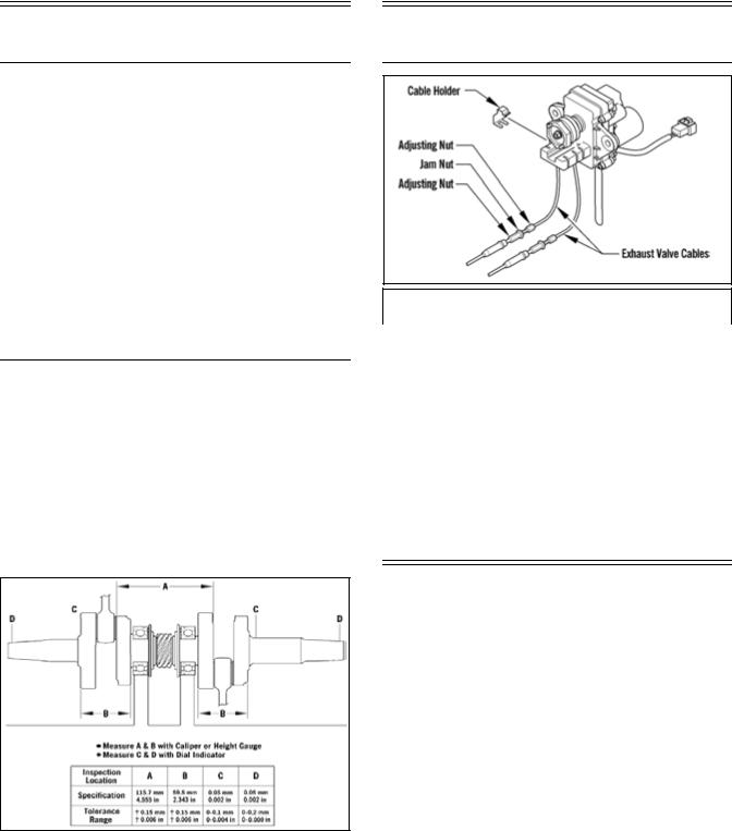
Crankshaft Runout/
Repair Specifications
To use the specifications, first refer to the drawing; then find the letter indicating the specification and refer to the chart below the illustration.
NOTE: The proper location for checking crankshaft runout is the very edge of the straight portion of the shaft where the oil seal makes contact. From the illustration, note that three check points are called out: at either end, out on the taper as shown, and also on the center bearing race. The crankshaft must be supported on the inner bearings using V blocks.
0747-810
Arctic Power Valve (APV)
System Specifications
APV CABLE LENGTH
6000 |
36.5 mm ± 1 mm |
|
|
|
|
|
|
0735-516
Electrical Specifications
Component |
Test Value |
+ Test Connections - |
|
Spark Plug Cap |
4000-6000 ohms |
cap end |
cap end |
Oil Level Sensor |
Less than 1 ohm |
terminal |
terminal |
|
(float end down) |
|
|
Ignition Switch |
Less than 1 ohm |
terminal |
terminal |
|
(key in OFF |
|
|
|
position) |
|
|
|
(Normally Open |
Ignition) |
|
Ignition Coil (Primary) |
0.24-0.36 ohm |
black/white |
white/blue |
(Secondary) |
5040-7560 ohms |
high tension wire |
high tension wire |
Charge Coil (1) |
8.8-13.2 ohms |
black/red |
green/red |
Charge Coil (2) |
8.8-13.2 ohms |
brown/white |
green/red |
Lighting Coil |
0.08-0.12 ohm |
yellow |
yellow |
Ignition Timing Sensor (1) |
148-222 ohms |
green/white |
brown/green |
Ignition Timing Sensor (2) |
148-222 ohms |
green/white |
brown/green |
Fuel Injector |
10-14 ohms |
terminal |
terminal |
Injection Coil |
15.2-22.8 ohms |
blue/white |
blue/white |
Fuel Pump Coil |
1.52-2.28 ohms |
orange |
orange |
Servomotor |
12 DC Volts |
red/black |
black/red |
|
|
(counterclock- |
(counterclock- |
|
|
wise) |
wise) |
|
|
black/red |
red/black |
|
|
(clockwise) |
(clockwise) |
Voltage Regulator/ |
9-14.5 DC Volts |
red/blue |
black |
Rectifier* |
|
|
|
* Harness plugged in
The main harness connectors must be unplugged (except on the primary coil and regulator/rectifier tests), the spark plugs removed and grounded, and the recoil starter rope briskly pulled.
5

NOTE: Lighting coil output is unregulated voltage.
! WARNING
Most voltages generated by the ignition system are sufficient to interrupt pacemakers! All technicians, especially those using pacemakers, must avoid contact with all electrical connections when pulling the recoil starter rope or after the engine has been started.
Component Voltage/
Resistance Chart —
Water Temperature
Temperature |
Volts |
Ohms |
|
Temperature |
Volts |
Ohms |
||
110 °C |
230 °F |
0.115 |
129 |
|
28 °C |
82 °F |
1.377 |
1800 |
108 °C |
226 °F |
0.129 |
137 |
|
26 °C |
79 °F |
1.459 |
1950 |
|
|
|
|
|
|
|
|
|
106 °C |
223 °F |
0.143 |
145 |
|
24 °C |
75 °F |
1.541 |
2100 |
|
|
|
|
|
|
|
|
|
104 °C |
219 °F |
0.157 |
153 |
|
22 °C |
72 °F |
1.623 |
2250 |
|
|
|
|
|
|
|
|
|
102 °C |
216 °F |
0.171 |
161 |
|
20 °C |
68 °F |
1.705 |
2400 |
|
|
|
|
|
|
|
|
|
100 °C |
212 °F |
0.185 |
169 |
|
18 °C |
64 °F |
1.806 |
2670 |
|
|
|
|
|
|
|
|
|
98 °C |
208 °F |
0.192 |
180 |
|
16 °C |
61 °F |
1.907 |
2940 |
|
|
|
|
|
|
|
|
|
96 °C |
205 °F |
0.199 |
191 |
|
14 °C |
57 °F |
2.008 |
3210 |
|
|
|
|
|
|
|
|
|
94 °C |
201 °F |
0.206 |
202 |
|
12 °C |
54 °F |
2.109 |
3480 |
|
|
|
|
|
|
|
|
|
92 °C |
198 °F |
0.213 |
213 |
|
10 °C |
50 °F |
2.210 |
3750 |
|
|
|
|
|
|
|
|
|
90 °C |
194 °F |
0.220 |
224 |
|
8 °C |
46 °F |
2.327 |
4170 |
|
|
|
|
|
|
|
|
|
88 °C |
190 °F |
0.235 |
240 |
|
6 °C |
43 °F |
2.444 |
4590 |
|
|
|
|
|
|
|
|
|
86 °C |
187 °F |
0.250 |
256 |
|
4 °C |
39 °F |
2.561 |
5010 |
|
|
|
|
|
|
|
|
|
84 °C |
183 °F |
0.265 |
273 |
|
2 °C |
36 °F |
2.678 |
5430 |
|
|
|
|
|
|
|
|
|
82 °C |
180 °F |
0.280 |
289 |
|
0 °C |
32 °F |
2.795 |
5850 |
|
|
|
|
|
|
|
|
|
80 °C |
176 °F |
0.295 |
305 |
|
-2 °C |
28 °F |
2.901 |
6510 |
|
|
|
|
|
|
|
|
|
78 °C |
172 °F |
0.317 |
327 |
|
-4 °C |
25 °F |
3.007 |
7170 |
|
|
|
|
|
|
|
|
|
76 °C |
169 °F |
0.339 |
349 |
|
-6 °C |
21 °F |
3.113 |
7830 |
|
|
|
|
|
|
|
|
|
74 °C |
165 °F |
0.361 |
371 |
|
-8 °C |
18 °F |
3.219 |
8490 |
|
|
|
|
|
|
|
|
|
72 °C |
162 °F |
0.383 |
393 |
|
-10 °C |
14 °F |
3.325 |
9150 |
|
|
|
|
|
|
|
|
|
70 °C |
158 °F |
0.405 |
415 |
|
-12 °C |
10 °F |
3.421 |
9422 |
|
|
|
|
|
|
|
|
|
68 °C |
154 °F |
0.438 |
445 |
|
-14 °C |
7 °F |
3.517 |
9694 |
|
|
|
|
|
|
|
|
|
66 °C |
151 °F |
0.471 |
475 |
|
-16 °C |
3 °F |
3.613 |
9966 |
|
|
|
|
|
|
|
|
|
64 °C |
147 °F |
0.504 |
505 |
|
-18 °C |
-0.4 °F |
3.709 |
10238 |
|
|
|
|
|
|
|
|
|
62 °C |
144 °F |
0.537 |
535 |
|
-20 °C |
-4 °F |
3.805 |
10510 |
|
|
|
|
|
|
|
|
|
60 °C |
140 °F |
0.570 |
565 |
|
-22 °C |
-8 °F |
3.885 |
13688 |
|
|
|
|
|
|
|
|
|
58 °C |
136 °F |
0.598 |
609 |
|
-24 °C |
-11 °F |
3.965 |
16866 |
|
|
|
|
|
|
|
|
|
56 °C |
133 °F |
0.626 |
653 |
|
-26 °C |
-15 °F |
4.045 |
20044 |
|
|
|
|
|
|
|
|
|
54 °C |
129 °F |
0.654 |
697 |
|
-28 °C |
-18 °F |
4.125 |
23222 |
|
|
|
|
|
|
|
|
|
52 °C |
126 °F |
0.682 |
741 |
|
-30 °C |
-22 °F |
4.205 |
26400 |
|
|
|
|
|
|
|
|
|
50 °C |
122 °F |
0.710 |
785 |
|
-32 °C |
-26 °F |
4.267 |
30520 |
|
|
|
|
|
|
|
|
|
48 °C |
118 °F |
0.759 |
849 |
|
-34 °C |
-29 °F |
4.329 |
34640 |
|
|
|
|
|
|
|
|
|
46 °C |
115 °F |
0.808 |
913 |
|
-36 °C |
-32 °F |
4.391 |
38760 |
|
|
|
|
|
|
|
|
|
44 °C |
111 °F |
0.857 |
977 |
|
-38 °C |
-36 °F |
4.453 |
42880 |
|
|
|
|
|
|
|
|
|
42 °C |
108 °F |
0.906 |
1041 |
|
-40 °C |
-40 °F |
4.515 |
47000 |
|
|
|
|
|
|
|
|
|
40 °C |
104 °F |
0.955 |
1105 |
|
-42 °C |
-44 °F |
4.553 |
55100 |
|
|
|
|
|
|
|
|
|
38 °C |
100 °F |
1.023 |
1214 |
|
-44 °C |
-47 °F |
4.591 |
63200 |
|
|
|
|
|
|
|
|
|
36 °C |
97 °F |
1.091 |
1323 |
|
-46 °C |
-51 °F |
4.629 |
71300 |
|
|
|
|
|
|
|
|
|
34 °C |
93 °F |
1.159 |
1432 |
|
-48 °C |
-54 °F |
4.667 |
79400 |
|
|
|
|
|
|
|
|
|
32 °C |
90 °F |
1.227 |
1541 |
|
-50 °C |
-58 °F |
4.705 |
87500 |
|
|
|
|
|
|
|
|
|
30 °C |
86 °F |
1.295 |
1650 |
|
|
|
|
|
|
|
|
|
|
|
|
|
|
6
R-XC Team Drive Clutch
Optional Components
P/N |
DESCRIPTION |
|
P/N |
|
DESCRIPTION |
|
||||||
|
|
DRIVE CLUTCH SPRINGS |
|
|
||||||||
0646-467 |
|
35/195 LB |
|
0646-878 |
|
105/285 LB |
|
|
||||
|
|
|
|
|
|
|
|
|
|
|
|
|
0646-468 |
|
35/215 LB |
|
0646-938 |
|
85/205 LB |
|
|
||||
|
|
|
|
|
|
|
|
|
|
|
|
|
0646-469 |
|
60/220 LB |
|
0646-939 |
|
105/205 LB |
|
|
||||
|
|
|
|
|
|
|
|
|
|
|
|
|
0646-470 |
|
60/240 LB |
|
0646-940 |
|
105/225 LB |
|
|
||||
|
|
|
|
|
|
|
|
|
|
|
|
|
0646-471 |
|
85/255 LB |
|
0646-482 |
|
120/235 LB |
|
|
||||
|
|
|
|
|
|
|
|
|
|
|
|
|
0646-472 |
|
85/275 LB |
|
0646-941 |
|
160/300 LB |
|
|
||||
|
|
|
|
|
|
|
|
|
|
|
|
|
0646-473 |
|
120/265 LB |
|
0646-942 |
|
165/310 LB |
|
|
||||
|
|
|
|
|
|
|
|
|
|
|
|
|
0646-474 |
|
120/285 LB |
|
0646-943 |
|
70/170 LB |
|
|
||||
|
|
|
|
|
|
|
|
|
|
|
|
|
0646-875 |
|
85/225 LB |
|
0646-944 |
|
80/180 LB |
|
|
||||
|
|
|
|
|
|
|
|
|
|
|
|
|
0646-876 |
|
85/235 LB |
|
0646-945 |
|
90/190 LB |
|
|
||||
|
|
|
|
|
|
|
|
|
|
|
|
|
0646-877 |
|
105/255 LB |
|
|
|
|
|
|
|
|
|
|
|
|
|
|
|
|
|
|
|
|
|
|
|
|
|
|
|
CAM |
ARMS |
|
|
|
|
|
||
0646-918 |
|
F7-48g |
|
0646-901 |
J13-90g |
|
|
|||||
0646-890 |
|
F7-50g |
|
0646-902 |
J14-56g |
|
|
|||||
0646-881 |
|
F7-52g |
|
0646-871 |
J14-58g |
|
|
|||||
0646-863 |
|
F7-54g |
|
0646-867 |
J14-60g |
|
|
|||||
0646-882 |
|
F7-56g |
|
0646-872 |
J14-62g |
|
|
|||||
0646-883 |
|
F7-58g |
|
0646-903 |
J14-64g |
|
|
|||||
0646-862 |
|
F7-60g |
|
0646-869 |
J14-66g |
|
|
|||||
0646-884 |
|
F7-62g |
|
0646-904 |
J14-68g |
|
|
|||||
0646-864 |
|
F7-64g |
|
0646-905 |
J14-70g |
|
|
|||||
0646-885 |
|
F7-66g |
|
0646-906 |
J14-72g |
|
|
|||||
0646-886 |
|
F7-68g |
|
0646-907 |
J14-74g |
|
|
|||||
0646-887 |
|
F7-70g |
|
0646-924 |
J14-76g |
|
|
|||||
0646-888 |
|
J13-60g |
|
0646-930 |
J15-52g |
|
|
|||||
0646-870 |
|
J13-62g |
|
0646-929 |
J15-56g |
|
|
|||||
0646-889 |
|
J13-64g |
|
0646-908 |
J15-58g |
|
|
|||||
0646-891 |
|
J13-66g |
|
0646-909 |
J15-60g |
|
|
|||||
0646-892 |
|
J13-68g |
|
0646-910 |
J15-62g |
|
|
|||||
0646-893 |
|
J13-70g |
|
0646-873 |
J15-64g |
|
|
|||||
0646-865 |
|
J13-72g |
|
0646-911 |
J15-66g |
|
|
|||||
0646-894 |
|
J13-74g |
|
0646-912 |
J15-68g |
|
|
|||||
0646-895 |
|
J13-76g |
|
0646-913 |
J15-70g |
|
|
|||||
0646-896 |
|
J13-78g |
|
0646-914 |
J13-48g |
|
|
|||||
0646-897 |
|
J13-80g |
|
0646-915 |
J13-50g |
|
|
|||||
0646-898 |
|
J13-82g |
|
0646-874 |
J13-52g |
|
|
|||||
0646-899 |
|
J13-84g |
|
0646-868 |
J13-54g |
|
|
|||||
0646-866 |
|
J13-86g |
|
0646-916 |
J13-56g |
|
|
|||||
0646-900 |
|
J13-88g |
|
0646-917 |
J13-58g |
|
|
|||||
|
|
|
|
|
|
|
|
|
|
|
|
|
|
|
|
|
DRIVEN CLUTCH |
|
|
|
|
|
|||
Torque |
|
Degree |
|
Spring |
|
Color |
|
Spring |
|
|||
Bracket |
|
|
|
|
Rate |
|
||||||
0648-779* |
|
58-46-36/ |
|
0648-749 |
|
Black/White |
|
160/260 |
|
|||
|
|
58-48-36 |
|
|
|
|
|
|
|
|
|
|
0648-775* |
|
52-42-46/ |
|
0648-702 |
|
Red/Black |
|
140/240 |
|
|||
|
|
52-44-46 |
|
|
|
|
|
|
|
|
|
|
0648-773* |
|
70-44-32/ |
|
0648-784 |
|
|
Black |
|
155/222 |
|
||
|
|
68-48-46 |
|
|
|
|
|
|
|
|
|
|
0648-789* |
|
68-48-36/ |
|
0648-790 |
|
Black/Light Blue |
|
180/260 |
|
|||
|
|
64-48-41 |
|
|
|
|
|
|
|
|
|
|
0648-791* |
|
48-44-36/ |
|
0648-792 |
|
Black/Orange |
|
180/280 |
|
|||
|
|
48-42-36 |
|
|
|
|
|
|
|
|
|
|
* Lightweight driven clutch only.
R-SX Arctic Cat Drive
Clutch/Driven Clutch
Optional Components
ARCTIC CAT DRIVE CLUTCH SPRING CHART
|
p/n |
Rate @ 2 9/16”Rate @ 1 5/16” |
Color |
|
LIGHT |
0646-439 |
50 lb |
250 lb |
Black/White |
|
0646-148 |
53 lb |
224 lb |
Blue |
|
0646-150 |
72 lb |
188 lb |
Silver |
|
0646-149 |
74 lb |
228 lb |
Red |
|
0646-432 |
74 lb |
228 lb |
Black/Red |
|
0646-433 |
75 lb |
275 lb |
Black/Gold |
|
0646-376 |
75 lb |
275 lb |
Gold |
|
0646-252 |
103 lb |
315 lb |
Green |
|
0646-147 |
114 lb |
267 lb |
Yellow/Green |
|
0646-373* |
114 lb |
257 lb |
Yellow/Green |
|
0646-155 |
121 lb |
240 lb |
Purple |
|
0646-229 |
122 lb |
285 lb |
Yellow/White |
|
0646-379* |
122 lb |
285 lb |
Yellow/White |
|
0646-035 |
143 lb |
286 lb |
Orange/ |
|
|
|
|
Black |
|
0646-447 |
143 lb |
286 lb |
Pink |
|
(Titanium) |
|
|
|
|
0646-367 |
143 lb |
250 lb |
Black |
|
0646-684 |
158 lb |
285 lb |
Black |
HEAVY |
0646-410 |
165 lb |
310 lb |
Black/Blue |
|
|
|
|
|
|
|
DRIVEN CLUTCH |
|
|
|
|
|
|
|
Torque |
Degree |
Spring |
Color |
Spring |
Bracket |
Rate |
|||
0648-779* 58-46-36/ |
0648-749 |
Black/White |
160/260 |
|
|
58-48-36 |
|
|
|
0648-775* 52-42-46/ |
0648-702 |
Red/Black |
140/240 |
|
|
52-44-46 |
|
|
|
0648-773* 70-44-32/ |
0648-784 |
Black |
155/222 |
|
|
68-48-46 |
|
|
|
0648-789* 68-48-36/ |
0648-790 |
Black/Light Blue |
180/260 |
|
|
64-48-41 |
|
|
|
0648-791* 48-44-36/ |
0648-792 |
Black/Orange |
180/280 |
|
|
48-42-36 |
|
|
|
*Lightweight driven clutch only.
7

R-SX Arctic Cat Drive
Clutch Cam Arms
(w/Set Screw)
ARCTIC CAT DRIVE CLUTCH CAM ARMS
p/n |
Grams |
p/n |
Grams |
|
|
|
|
0746-661 |
52.0 |
0746-712 |
77.0 |
0746-662 |
52.0 |
0746-713 |
48.0 |
0746-663 |
52.0 |
0746-715 |
77.0 |
0746-664 |
52.0 |
0746-716 |
73.0 |
0746-666 |
55.0 |
0746-742 |
83.5 |
0746-668 |
55.0 |
0746-744 |
50.0 |
0746-669 |
60.0 |
0746-748 |
46.0 |
0746-670 |
65.0 |
0746-749 |
65.0 |
0746-671 |
70.0 |
0746-771 |
44.0 |
0746-672 |
75.0 |
0746-772 |
42.0 |
0746-673 |
80.0 |
0746-773 |
85.0 |
0746-676 |
70.0 |
0746-786 |
63.0 |
0746-678 |
55.0 |
0746-787 |
44.0 |
0746-687 |
57.0 |
0746-788 |
47.5 |
0746-689 |
69.0 |
0746-789 |
42.0 |
0746-690 |
47.0 |
0746-791 |
60.0 |
0746-691 |
44.0 |
0746-792 |
47.0 |
0746-692 |
50.0 |
0746-793 |
63.0 |
0746-694 |
63.0 |
0746-814 |
83.0 |
0746-695 |
67.0 |
0746-821 |
82.0 |
0746-696 |
63.0 |
0746-822 |
71.5 |
0746-698 |
64.0 |
0746-824 |
66.0 |
0746-699 |
66.0 |
0746-825 |
50.0 |
0746-701 |
49.0 |
0746-826 |
64.0* |
0746-702 |
57.5 |
0746-830 |
60.0 |
0746-703 |
68.0 |
|
|
0746-704 |
51.0 |
|
|
0746-708 |
51.0 |
|
|
0746-710 |
72.0 |
|
|
|
|
|
|
* Notched Cam Arm
8

Chain Case Performance
Calibrations
NOTE: The following table should be used as a guide only. The vehicle speeds should be based on 12% overdrive.
Drive |
Gear |
Ratio |
Chain |
|
|
|
|
|
|
Engine RPM |
|
|
|
|
|
|
||||
Sprocket |
Ratio |
|
|
|
|
|
|
|
|
|
|
|
|
|||||||
|
|
|
|
|
|
|
|
|
|
|
|
|
|
|
|
|
|
|
|
|
|
Top |
Btm |
|
|
6200 |
6400 |
6600 |
6800 |
7000 |
7200 |
7400 |
7600 |
7800 |
8000 |
8200 |
8400 |
8600 |
8800 |
9000 |
|
|
|
|
|
|
|
|
|
Vehicle Speed (mph) |
|
|
|
|
|
|||||||
|
|
|
|
|
|
|
|
|
|
|
|
|
|
|
||||||
8 Tooth |
19 |
50 |
0.380 |
90 |
57 |
59 |
61 |
63 |
65 |
66 |
68 |
70 |
72 |
74 |
76 |
77 |
79 |
81 |
83 |
|
(2.86" |
|
|
|
|
|
|
|
|
|
|
|
|
|
|
|
|
|
|
|
|
21 |
49 |
0.429 |
90 |
64 |
67 |
69 |
71 |
73 |
75 |
77 |
79 |
81 |
83 |
85 |
87 |
89 |
91 |
94 |
||
pitch) |
||||||||||||||||||||
20 |
46 |
0.435 |
88 |
65 |
67 |
70 |
72 |
74 |
76 |
78 |
80 |
82 |
84 |
86 |
89 |
91 |
93 |
95 |
||
|
||||||||||||||||||||
|
23 |
51 |
0.451 |
92 |
68 |
70 |
72 |
74 |
77 |
79 |
81 |
83 |
85 |
88 |
90 |
92 |
94 |
96 |
98 |
|
|
22 |
48 |
0.458 |
90 |
69 |
71 |
73 |
76 |
78 |
80 |
82 |
84 |
87 |
89 |
91 |
93 |
96 |
98 |
100 |
|
|
24 |
50 |
0.480 |
92 |
72 |
75 |
77 |
79 |
81 |
84 |
86 |
88 |
91 |
93 |
95 |
98 |
100 |
102 |
105 |
|
|
21 |
41 |
0.512 |
86 |
77 |
80 |
82 |
84 |
87 |
89 |
92 |
94 |
97 |
99 |
102 |
104 |
107 |
109 |
112 |
|
|
21 |
38 |
0.553 |
84 |
83 |
86 |
88 |
91 |
94 |
97 |
99 |
102 |
105 |
107 |
110 |
113 |
115 |
118 |
121 |
|
|
20 |
35 |
0.571 |
82 |
86 |
89 |
91 |
94 |
97 |
100 |
103 |
105 |
108 |
111 |
114 |
116 |
119 |
122 |
125 |
|
|
23 |
40 |
0.575 |
86 |
86 |
89 |
92 |
95 |
98 |
100 |
103 |
106 |
109 |
112 |
114 |
117 |
120 |
123 |
126 |
|
|
22 |
37 |
0.595 |
84 |
89 |
92 |
95 |
98 |
101 |
104 |
107 |
110 |
112 |
115 |
118 |
121 |
124 |
127 |
130 |
|
|
24 |
39 |
0.615 |
86 |
93 |
96 |
99 |
101 |
104 |
107 |
110 |
113 |
116 |
119 |
122 |
125 |
128 |
131 |
134 |
|
|
23 |
36 |
0.639 |
84 |
96 |
99 |
102 |
105 |
108 |
112 |
115 |
118 |
121 |
124 |
127 |
130 |
133 |
136 |
139 |
|
|
24 |
35 |
0.686 |
84 |
103 |
106 |
110 |
113 |
116 |
120 |
123 |
126 |
130 |
133 |
136 |
140 |
143 |
146 |
150 |
|
8 Tooth |
19 |
50 |
0.380 |
90 |
60 |
62 |
64 |
66 |
68 |
70 |
72 |
73 |
75 |
77 |
79 |
81 |
83 |
85 |
87 |
|
(3.0" pitch) |
|
|
|
|
|
|
|
|
|
|
|
|
|
|
|
|
|
|
|
|
21 |
49 |
0.429 |
90 |
68 |
70 |
72 |
74 |
76 |
79 |
81 |
83 |
85 |
87 |
89 |
92 |
94 |
96 |
98 |
||
|
20 |
46 |
0.435 |
88 |
69 |
71 |
73 |
75 |
77 |
80 |
82 |
84 |
86 |
88 |
91 |
93 |
95 |
97 |
100 |
|
|
23 |
51 |
0.451 |
92 |
71 |
73 |
76 |
78 |
80 |
83 |
85 |
87 |
89 |
92 |
94 |
96 |
99 |
101 |
103 |
|
|
22 |
48 |
0.458 |
90 |
72 |
75 |
77 |
79 |
82 |
84 |
86 |
89 |
91 |
93 |
96 |
98 |
100 |
103 |
105 |
|
|
24 |
50 |
0.480 |
92 |
76 |
78 |
81 |
83 |
85 |
88 |
90 |
93 |
95 |
98 |
100 |
103 |
105 |
107 |
110 |
|
|
21 |
41 |
0.512 |
86 |
81 |
83 |
86 |
89 |
91 |
94 |
96 |
99 |
102 |
104 |
107 |
109 |
112 |
115 |
117 |
|
|
21 |
38 |
0.553 |
84 |
87 |
90 |
93 |
96 |
98 |
101 |
104 |
107 |
110 |
112 |
115 |
118 |
121 |
124 |
127 |
|
|
20 |
35 |
0.571 |
82 |
90 |
93 |
96 |
99 |
102 |
105 |
108 |
110 |
113 |
116 |
119 |
122 |
125 |
128 |
131 |
|
|
23 |
40 |
0.575 |
86 |
91 |
94 |
97 |
99 |
102 |
105 |
108 |
111 |
114 |
117 |
120 |
123 |
126 |
129 |
132 |
|
|
22 |
37 |
0.595 |
84 |
94 |
97 |
100 |
103 |
106 |
109 |
112 |
115 |
118 |
121 |
124 |
127 |
130 |
133 |
136 |
|
|
24 |
39 |
0.615 |
86 |
97 |
100 |
103 |
106 |
110 |
113 |
116 |
119 |
122 |
125 |
128 |
132 |
135 |
138 |
141 |
|
|
23 |
36 |
0.639 |
84 |
101 |
104 |
107 |
111 |
114 |
117 |
120 |
124 |
127 |
130 |
133 |
137 |
140 |
143 |
146 |
|
|
24 |
35 |
0.686 |
84 |
108 |
112 |
115 |
119 |
122 |
126 |
129 |
133 |
136 |
140 |
143 |
147 |
150 |
154 |
157 |
|
9 Tooth |
19 |
50 |
0.380 |
90 |
57 |
58 |
60 |
62 |
64 |
66 |
68 |
69 |
71 |
73 |
75 |
77 |
79 |
80 |
82 |
|
(2.52" |
|
|
|
|
|
|
|
|
|
|
|
|
|
|
|
|
|
|
|
|
21 |
49 |
0.429 |
90 |
64 |
66 |
68 |
70 |
72 |
74 |
76 |
78 |
80 |
82 |
84 |
87 |
89 |
91 |
93 |
||
pitch) |
||||||||||||||||||||
20 |
46 |
0.435 |
88 |
65 |
67 |
69 |
71 |
73 |
75 |
77 |
79 |
82 |
84 |
86 |
88 |
90 |
92 |
94 |
||
|
||||||||||||||||||||
|
23 |
51 |
0.451 |
92 |
67 |
69 |
72 |
74 |
76 |
78 |
80 |
82 |
85 |
87 |
89 |
91 |
93 |
95 |
98 |
|
|
22 |
48 |
0.458 |
90 |
68 |
71 |
73 |
75 |
77 |
79 |
82 |
84 |
86 |
88 |
90 |
93 |
95 |
97 |
99 |
|
|
24 |
50 |
0.480 |
92 |
72 |
74 |
76 |
78 |
81 |
83 |
85 |
88 |
90 |
92 |
95 |
97 |
99 |
102 |
104 |
|
|
21 |
41 |
0.512 |
86 |
76 |
79 |
81 |
84 |
86 |
89 |
91 |
94 |
96 |
99 |
101 |
103 |
106 |
108 |
111 |
|
|
21 |
38 |
0.553 |
84 |
82 |
85 |
88 |
90 |
93 |
96 |
98 |
101 |
104 |
106 |
109 |
112 |
114 |
117 |
120 |
|
|
20 |
35 |
0.571 |
82 |
85 |
88 |
91 |
93 |
96 |
99 |
102 |
104 |
107 |
110 |
113 |
115 |
118 |
121 |
124 |
|
|
23 |
40 |
0.575 |
86 |
86 |
88 |
91 |
94 |
97 |
100 |
102 |
105 |
108 |
111 |
113 |
116 |
119 |
122 |
124 |
|
|
22 |
37 |
0.595 |
84 |
89 |
91 |
94 |
97 |
100 |
103 |
106 |
109 |
112 |
114 |
117 |
120 |
123 |
126 |
129 |
|
|
24 |
39 |
0.615 |
86 |
92 |
95 |
98 |
101 |
104 |
107 |
109 |
112 |
115 |
118 |
121 |
124 |
127 |
130 |
133 |
|
|
23 |
36 |
0.639 |
84 |
95 |
98 |
101 |
104 |
108 |
111 |
114 |
117 |
120 |
123 |
126 |
129 |
132 |
135 |
138 |
|
|
24 |
35 |
0.686 |
84 |
102 |
106 |
109 |
112 |
115 |
119 |
122 |
125 |
129 |
132 |
135 |
138 |
142 |
145 |
148 |
|
9
Drive |
Gear |
Ratio |
Chain |
|
|
|
|
|
|
Engine RPM |
|
|
|
|
|
|
||||
Sprocket |
Ratio |
|
|
|
|
|
|
|
|
|
|
|
|
|||||||
|
|
|
|
|
|
|
|
|
|
|
|
|
|
|
|
|
|
|
|
|
|
Top |
Btm |
|
|
6200 |
6400 |
6600 |
6800 |
7000 |
7200 |
7400 |
7600 |
7800 |
8000 |
8200 |
8400 |
8600 |
8800 |
9000 |
|
|
|
|
|
|
|
|
|
Vehicle Speed (mph) |
|
|
|
|
|
|||||||
|
|
|
|
|
|
|
|
|
|
|
|
|
|
|
||||||
|
|
|
|
|
|
|
|
|
|
|
|
|
|
|
|
|
|
|
|
|
9 Tooth |
19 |
50 |
0.380 |
90 |
64 |
66 |
68 |
71 |
73 |
75 |
77 |
79 |
81 |
83 |
85 |
87 |
89 |
91 |
93 |
|
(2.86" |
|
|
|
|
|
|
|
|
|
|
|
|
|
|
|
|
|
|
|
|
21 |
49 |
0.429 |
90 |
73 |
75 |
77 |
80 |
82 |
84 |
87 |
89 |
91 |
94 |
96 |
98 |
101 |
103 |
105 |
||
pitch) |
||||||||||||||||||||
20 |
46 |
0.435 |
88 |
74 |
76 |
78 |
81 |
83 |
85 |
88 |
90 |
93 |
95 |
97 |
100 |
102 |
104 |
107 |
||
|
||||||||||||||||||||
|
23 |
51 |
0.451 |
92 |
76 |
79 |
81 |
84 |
86 |
89 |
91 |
94 |
96 |
98 |
101 |
103 |
106 |
108 |
111 |
|
|
22 |
48 |
0.458 |
90 |
78 |
80 |
83 |
85 |
88 |
90 |
93 |
95 |
98 |
100 |
103 |
105 |
108 |
110 |
113 |
|
|
24 |
50 |
0.480 |
92 |
81 |
84 |
86 |
89 |
92 |
94 |
97 |
100 |
102 |
105 |
107 |
110 |
113 |
115 |
118 |
|
|
21 |
41 |
0.512 |
86 |
87 |
89 |
92 |
95 |
98 |
101 |
103 |
106 |
109 |
112 |
115 |
117 |
120 |
123 |
126 |
|
|
21 |
38 |
0.553 |
84 |
93 |
97 |
100 |
103 |
106 |
109 |
112 |
115 |
118 |
121 |
124 |
127 |
130 |
133 |
136 |
|
|
20 |
35 |
0.571 |
82 |
97 |
100 |
103 |
106 |
109 |
112 |
115 |
118 |
122 |
125 |
128 |
131 |
134 |
137 |
140 |
|
|
23 |
40 |
0.575 |
86 |
97 |
100 |
104 |
107 |
110 |
113 |
116 |
119 |
122 |
126 |
129 |
132 |
135 |
138 |
141 |
|
|
22 |
37 |
0.595 |
84 |
101 |
104 |
107 |
110 |
114 |
117 |
120 |
123 |
127 |
130 |
133 |
136 |
140 |
143 |
146 |
|
|
24 |
39 |
0.615 |
86 |
104 |
107 |
111 |
114 |
118 |
121 |
124 |
128 |
131 |
134 |
138 |
141 |
144 |
148 |
151 |
|
|
23 |
36 |
0.639 |
84 |
108 |
112 |
115 |
119 |
122 |
126 |
129 |
132 |
136 |
139 |
143 |
146 |
150 |
153 |
157 |
|
|
24 |
35 |
0.686 |
84 |
116 |
120 |
123 |
127 |
131 |
135 |
138 |
142 |
146 |
150 |
153 |
157 |
161 |
165 |
168 |
|
10 Tooth |
19 |
50 |
0.380 |
90 |
63 |
65 |
67 |
69 |
71 |
73 |
75 |
77 |
79 |
81 |
83 |
85 |
87 |
89 |
91 |
|
(2.52" |
|
|
|
|
|
|
|
|
|
|
|
|
|
|
|
|
|
|
|
|
21 |
49 |
0.429 |
90 |
71 |
73 |
76 |
78 |
80 |
82 |
85 |
87 |
89 |
92 |
94 |
96 |
98 |
101 |
103 |
||
pitch) |
||||||||||||||||||||
20 |
46 |
0.435 |
88 |
72 |
74 |
77 |
79 |
81 |
84 |
86 |
88 |
91 |
93 |
95 |
98 |
100 |
102 |
105 |
||
|
||||||||||||||||||||
|
23 |
51 |
0.451 |
92 |
75 |
77 |
80 |
82 |
84 |
87 |
89 |
92 |
94 |
96 |
99 |
101 |
104 |
106 |
108 |
|
|
22 |
48 |
0.458 |
90 |
76 |
78 |
81 |
83 |
86 |
88 |
91 |
93 |
96 |
98 |
100 |
103 |
105 |
108 |
110 |
|
|
24 |
50 |
0.480 |
92 |
80 |
82 |
85 |
87 |
90 |
92 |
95 |
97 |
100 |
103 |
105 |
108 |
110 |
113 |
115 |
|
|
21 |
41 |
0.512 |
86 |
85 |
88 |
90 |
93 |
96 |
99 |
101 |
104 |
107 |
109 |
112 |
115 |
118 |
120 |
123 |
|
|
21 |
38 |
0.553 |
84 |
92 |
94 |
97 |
100 |
103 |
106 |
109 |
112 |
115 |
118 |
121 |
124 |
127 |
130 |
133 |
|
|
20 |
35 |
0.571 |
82 |
95 |
98 |
101 |
104 |
107 |
110 |
113 |
116 |
119 |
122 |
125 |
128 |
131 |
134 |
137 |
|
|
23 |
40 |
0.575 |
86 |
95 |
98 |
101 |
104 |
108 |
111 |
114 |
117 |
120 |
123 |
126 |
129 |
132 |
135 |
138 |
|
|
22 |
37 |
0.595 |
84 |
98 |
102 |
105 |
108 |
111 |
114 |
118 |
121 |
124 |
127 |
130 |
133 |
137 |
140 |
143 |
|
|
24 |
39 |
0.615 |
86 |
102 |
105 |
108 |
112 |
115 |
118 |
122 |
125 |
128 |
132 |
135 |
138 |
141 |
145 |
148 |
|
|
23 |
36 |
0.639 |
84 |
106 |
109 |
113 |
116 |
119 |
123 |
126 |
130 |
133 |
137 |
140 |
143 |
147 |
150 |
154 |
|
|
24 |
35 |
0.686 |
84 |
114 |
117 |
121 |
125 |
128 |
132 |
136 |
139 |
143 |
147 |
150 |
154 |
158 |
161 |
165 |
|
NOTE: The above gearing options are combinations which allow acceptable chain tension. Any other combinations will not allow acceptable chain tension.
10

Chains and Sprockets
p/n |
Sprocket |
3602-170 |
19T FWD (13 WIDE/19 SPLINE) – Optional |
|
|
3602-169 |
20T FWD (13 WIDE/19 SPLINE) – R-SX |
|
|
2602-966 |
21T FWD (13 WIDE/19 SPLINE) – Optional |
|
|
3602-171 |
22T FWD (13 WIDE/19 SPLINE) – Optional |
|
|
2602-967 |
23T FWD (13 WIDE/19 SPLINE) – R-XC |
|
|
|
|
2602-831 |
35T (13 WIDE/34 SPLINE) |
|
|
2602-833 |
36T (13 WIDE/34 SPLINE) |
|
|
2602-834 |
37T (13 WIDE/34 SPLINE) |
|
|
2602-836 |
38T (13 WIDE/34 SPLINE) |
|
|
2602-745 |
41T (13 WIDE/34 SPLINE) |
|
|
2602-790 |
48T (13 WIDE/34 SPLINE) |
|
|
2602-758 |
49T (13 WIDE/34 SPLINE) |
|
|
2602-746 |
50T (13 WIDE/34 SPLINE) |
|
|
|
|
2602-874 |
48T (13 WIDE/34 SPLINE) ALUM |
|
|
2602-875 |
49T (13 WIDE/34 SPLINE) ALUM |
|
|
2602-876 |
50T (13 WIDE/34 SPLINE) ALUM |
|
|
|
|
1702-402 |
40T TOS-ASSY |
|
|
1702-403 |
49T TOS-ASSY |
|
|
|
|
p/n |
Chain |
2602-837 |
84P (13 WIDE) |
|
|
2602-743 |
86P (13 WIDE) |
|
|
2602-760 |
90P (13 WIDE) |
|
|
2602-744 |
92P (13 WIDE) |
|
|
2602-944 |
96P (13 WIDE) |
|
|
|
|
2602-839 |
86P (15 WIDE) |
|
|
2602-840 |
90P (15 WIDE) |
|
|
2602-841 |
92P (15 WIDE) |
|
|
|
|
|
|
Rear Spring Selection
Below is a list of rear suspension springs and specifications. A longer spring in areas (D) and (E) can be selected if cut off to match the original spring. The replacement spring must match the original spring in areas (C), (D), and (E).
0730-218
|
Wire |
Angle |
# of |
Coil |
Length |
Length |
Degree |
p/n |
Diameter |
Width |
|||||
|
(A) |
(B) |
Coils |
(C) |
(D) |
(E) |
(In lb) |
|
|
|
|
|
|
|
|
1704-382/383 |
.359 |
90° |
5.75 |
3.00 |
15.62 |
4.60 |
17 |
(Light) |
|
|
|
|
|
|
|
1704-384/385 |
.375 |
90° |
5.75 |
3.00 |
15.62 |
4.60 |
20 |
(Heavy) |
|
|
|
|
|
|
|
1704-916/917 |
.405 |
120° |
5.90 |
3.20 |
15.62 |
4.70 |
24 |
|
|
|
|
|
|
|
|
2704-224/225 |
.437 |
105° |
6.80 |
3.75 |
15.62 |
4.70 |
27.3 |
|
|
|
|
|
|
|
|
1704-576/577 |
.405 |
90° |
6.75 |
3.65 |
18.50 |
5.50 |
18.5 |
2704-384/385 |
.405 |
115° |
6.80 |
3.65 |
15.62 |
4.70 |
18.9 |
|
|
|
|
|
|
|
|
2704-380/381** |
.437 |
92° |
6.75 |
3.75 |
15.62 |
4.70 |
27.4 |
|
|
|
|
|
|
|
|
2704-382/383* |
.405 |
89° |
6.75 |
3.65 |
15.62 |
4.70 |
18.9 |
* Production (R-XC) ** Production (R-SX)
NOTE: The wire diameter and length of the spring have a large influence over the valving of the shocks.
Installed Spring Rate
Chart
p/n |
Suspension Fully |
Suspension Fully |
|
Extended |
Extended |
||
|
(in.-lb – Adjuster Set 1 & 1) |
(in.-lb – Adjuster Set 3 & 3) |
|
1704-382/383 |
1360 |
1700 |
|
|
|
|
|
1704-384/385 |
1600 |
2001 |
|
1704-916/917 |
480 |
960 |
|
|
|
|
|
2704-224/225 |
1350 |
1890 |
|
|
|
|
|
1704-576/577 |
1480 |
1850 |
|
2704-380/381 |
2082 |
2630 |
|
|
|
|
|
2704-382/383 |
1550 |
1928 |
|
|
|
|
|
2704-384/385 |
567 |
945 |
|
p/n |
Suspension Fully |
Suspension Fully |
|
Collapsed |
Collapsed |
||
|
(in.-lb – Adjuster Set 1 & 1) |
(in.-lb – Adjuster Set 3 & 3) |
|
1704-382/383 |
3740 |
4080 |
|
|
|
|
|
1704-384/385 |
4411 |
4812 |
|
|
|
|
|
1704-916/917 |
3840 |
4320 |
|
2704-224/225 |
5130 |
5670 |
|
|
|
|
|
1704-576/577 |
4070 |
4440 |
|
|
|
|
|
2704-380/381 |
5918 |
6466 |
|
2704-382/383 |
4196 |
4574 |
|
|
|
|
|
2704-384/385 |
3213 |
3591 |
|
|
|
|
|
|
|
|
|
|
|
|
|
Front Suspension
Sway Bar
Sway Bar p/n |
Bushing p/n |
Description |
|
|
|
2703-615 |
2603-944/945 (inc.) |
11.1 mm diameter |
|
|
|
2703-793 |
2603-946/947 (inc.) |
12.7 mm diameter |
|
|
|
2703-794 |
2603.948/949 (inc.) |
14.7 mm diameter |
|
|
|
NOTE: Sway Bar Mounting Kit (p/n 6639-001).
11

Rebuildable Shock Tools
Required
p/n |
Tool |
|
|
|
|
0744-020 |
Inflation Needle |
|
|
|
|
0644-486 |
Gas Shock Retaining Blocks |
|
|
|
|
0644-544 |
Replacement Needle |
|
|
|
|
0644-169 |
Piston Location Tool |
|
|
|
|
0644-151 |
Nitrogen Regulator |
|
|
|
|
0644-268 |
Bearing Cap Seal Protector |
|
|
|
|
0644-403 |
Bearing Cap Seal Protector (1/2-in. O.D. x 3/8 in. I.D.) |
|
|
|
|
0644-404 |
Bearing Cap Seal Protector (5/8-in. O.D. x 3/8 in. I.D.) |
|
|
|
|
0644-542 |
Bearing Cap Seal Protector (5/8 in. O.D. x 1/2 in. I.D.) |
|
|
|
|
0644-543 |
Gas Shock Shaft Clamping Tool |
|
|
|
|
0644-350 |
Floating Piston Location Gauge |
|
|
|
|
0644-539 |
Inflation Needle Replacement Tip |
|
|
|
|
0744-072 |
Float Shock Spanner Wrench |
|
|
|
|
0644-584 |
Air Sleeve Bushing Installation Tool |
|
|
|
|
0644-585 |
Air Sleeve Bushing Installation Tool |
|
|
|
|
0644-456 |
Bullet Air Sleeve Bushing Installation Tool |
|
|
|
|
|
|
|
|
|
|
Optional Front Arm
Shock Springs — R-XC
p/n |
lbs |
Length (Inches) |
|
|
|
2704-755 |
100/250 |
7.75 |
|
|
|
2704-228 |
100/250 |
7.75 |
|
|
|
2704-229 |
160/260 |
7.75 |
|
|
|
1704-819 |
230 |
7.50 |
|
|
|
1704-820 |
170 |
7.50 |
|
|
|
1704-821 |
190 |
7.50 |
|
|
|
1704-822 |
210 |
7.50 |
|
|
|
1704-831 |
250 |
7.50 |
|
|
|
|
Ice Racing Springs |
|
2704-749 |
70 |
6 |
|
|
|
2704-750 |
90 |
6 |
|
|
|
2704-751 |
110 |
6 |
|
|
|
|
|
|
|
|
|
Optional Front Arm
Shock Springs — R-SX
p/n |
lbs |
Length (Inches) |
|
|
|
3704-094 |
90/250 |
8.25 |
|
|
|
3704-095 |
135 |
8.25 |
|
|
|
3704-152 |
300 |
7 |
|
|
|
3704-351 |
200 |
7 |
|
|
|
3704-352 |
225 |
7 |
|
|
|
3704-353* |
250 |
7 |
|
|
|
3704-354 |
275 |
7 |
|
|
|
* Stock Spring
Optional Dual Rate
Spring Chart (DSR)
Dual |
Ride-in |
Take-over |
Communication |
Transition |
Rate |
Spring |
Spring |
Length |
Point |
100/200 |
200 lb x 2.15" |
200 lb x 6” |
1” |
1.70” |
|
|
|
|
|
|
p/n 3704-037 |
p/n 3704-038 |
0.5” |
2.70” |
|
|
|
|
|
90/200 |
170 lb x 2.20” |
200 lb x 6” |
1” |
1.65” |
|
|
|
|
|
|
p/n 3704-036 |
p/n 3704-038 |
0.5” |
2.50” |
|
|
|
|
|
80/200 |
140 lb x 2.40” |
200 lb x 6” |
1” |
1.80” |
|
|
|
|
|
|
p/n 3704-035 |
p/n 3704-038 |
0.5” |
2.65” |
|
|
|
|
|
50/200 |
70 lb x 2.55” |
200 lb x 6” |
1” |
1.65” |
|
|
|
|
|
|
p/n 3704-033 |
p/n 3704-038 |
0.5” |
2.30” |
|
|
|
|
|
110/250 |
200 lb x 2.15” |
250 lb x 6” |
1” |
1.52” |
|
|
|
|
|
|
p/n 3704-037 |
p/n 3704-039 |
0.5” |
2.41” |
|
|
|
|
|
100/250* |
170 lb x 2.20” |
250 lb x 6” |
1” |
1.50” |
|
|
|
|
|
|
p/n 3704-036 |
p/n 3704-039 |
0.5” |
2.33” |
|
|
|
|
|
90/250 |
140 lb x 2.40” |
250 lb x 6” |
1” |
1.75” |
|
|
|
|
|
|
p/n 3704-035 |
p/n 3704-039 |
0.5” |
2.50” |
|
|
|
|
|
55/250 |
70 lb x 2.55” |
250 lb x 6” |
1” |
1.60” |
|
|
|
|
|
|
p/n 3704-033 |
p/n 3704-039 |
0.5” |
2.25” |
|
|
|
|
|
120/300 |
200 lb x 2.15” |
300 lb x 6” |
1” |
1.40” |
|
|
|
|
|
|
p/n 3704-037 |
p/n 3704-040 |
0.5” |
2.25” |
|
|
|
|
|
110-300 |
170 lb x 2.20” |
300 lb x 6” |
1” |
1.40” |
|
|
|
|
|
|
3704-036 |
p/n 3704-040 |
0.5” |
2.20” |
|
|
|
|
|
95/300 |
140 lb x 2.40” |
300 lb x 6” |
1” |
1.60” |
|
|
|
|
|
|
3704-035 |
p/n 3704-040 |
0.5” |
2.35” |
|
|
|
|
|
55/300 |
70 lb x 2.55” |
300 lb x 6” |
1” |
1.55” |
|
|
|
|
|
|
p/n 3704-033 |
p/n 3704-040 |
0.5” |
2.15” |
|
|
|
|
|
* Stock Spring (R-XC)
12

Valve Stacks/Specifications (R-XC)
Ski Shock Part Number |
Compression (Piston Side) |
Rebound (Piston Side) |
3703-813 |
1.300 x 0.008 in. (DB) |
1.100 x 0.010 in. |
|
|
|
Extended Length: 18.98 in. |
1.300 x 0.006 in. |
0.800 x 0.006 in. |
|
|
|
Collapsed Length: 13.28 in. |
1.300 x 0.006 in. |
1.125 x 0.080 in. (Backup) |
Stroke: 5.7 in. |
0.800 x 0.008 in. |
0.750 x 0.080 in. (Backup) |
|
|
|
|
1.300 x 0.008 in. |
0.750 x 0.080 in. (Backup) |
Rebuild Kit: p/n 3603-522 |
1.250 x 0.008 in. |
0.750 x 0.080 in. (Backup) |
|
1.100 x 0.008 in. |
|
|
|
|
|
1.000 x 0.008 in. |
|
|
|
|
|
0.900 x 0.008 in. |
|
|
0.800 x 0.008 in. |
|
|
|
|
IFP Depth: 1.8 in. |
1.125 x 0.093 in. (Top Out) |
|
Piston Orifice: None |
|
|
QS3 @ 2nd Setting; RB Knob @ 12 clicks from full closed.
Eyelets tightened to 3.9 kg-m (28 ft-lb) (Green Loctite #620 on threads). Piston nut tightened to 3.0 kg-m (22 ft-lb). Tighten shaft nut to 3.0 kg-m (22 ft-lb). Shocks charged at 250 psi.
Front Arm Shock Part Number |
Compression (Piston Side) |
Rebound (Piston Side) |
3704-348 |
1.300 x 0.010 (SB) |
1.100 x 0.010 in. |
Extended Length: 12.41 in. |
1.300 x 0.006 in. |
1.100 x 0.010 in. |
|
|
|
Collapsed Length: 8.63 in. |
1.300 x 0.006 in. |
1.000 x 0.010 in. |
Stroke: 3.78 in. |
1.300 x 0.006 in. |
0.900 x 0.010 in. |
|
0.700 x 0.006 |
0.800 x 0.010 in. |
|
|
|
Rebuild Kit: p/n 4604-189 |
1.300 x 0.008 in. |
0.700 x 0.010 in. |
|
|
|
|
1.250 x 0.008 in. |
0.620 x 0.080 in. (Backup) |
|
1.100 x 0.008 in. |
0.620 x 0.080 in. (Backup) |
|
|
|
|
1.000 x 0.008 in. |
|
IFP Depth: 1.4 in. |
0.800 x 0.008 in. |
|
Piston Orifice: None |
0.700 x 0.008 in. |
|
|
|
|
|
1.125 x 0.080 in. (Top Out) |
|
|
|
|
QS3 @ 2nd Setting. Eyelets tightened to 3.9 kg-m (28 ft-lb) (Green Loctite #620 on threads).
Piston nut tightened to 3.0 kg-m (22 ft-lb). Tighten shaft nut to 3.9 kg-m (28 ft-lb). Shock charged at 250 psi.
Rear Arm Shock Part Number |
Compression |
Rebound (Piston Side) |
|
(Piston Side) |
|||
|
|
||
|
|
|
|
3704-342 |
1.600 x 0.004 in. (XSB) |
1.425 x 0.015 in. |
|
Extended Length: 14.44 in. |
1.600 x 0.010 in. |
1.425 x 0.015 in. |
|
|
|
|
|
Collapsed Length: 10.02 in. |
1.600 x 0.010 in. |
1.425 x 0.012 in. |
|
|
|
|
|
Stroke: 4.42 in. |
1.100 x 0.006 in. |
1.350 x 0.012 in. |
|
|
1.600 x 0.012 in. |
1.100 x 0.012 in. |
|
|
|
|
|
Rebuild Kit: p/n 4604-160 |
1.600 x 0.012 in. |
0.950 x 0.012 in. |
|
|
1.600 x 0.012 in. |
0.800 x 0.020 in. |
|
|
1.425 x 0.010 in. |
0.800 x 0.020 in. |
|
|
|
|
|
|
1.350 x 0.010 in. |
0.750 x 0.080 in. (Backup) |
|
|
|
|
|
|
1.100 x 0.008 in. |
0.750 x 0.100 in. (Backup) |
|
Piston Depth: 2.10 in. |
1.570 x 0.128 in. (Top Out) |
|
|
Piston Orifice: None |
|
|
|
|
|
QS3 @ 2nd Setting; RB Knob @ 4 clicks counterclockwise. Shock charged at 250 psi.
Eyelets tightened to 3.9 kg-m (28 ft-lb) (Green Loctite #620 on threads). Piston nut tightened to 3.0 kg-m (22 ft-lb). Tighten the shaft nut to 3.9 kg-m (28 ft-lb).
13

Valve Stacks/Specifications (R-SX)
Ski Shock Part Number |
Compression (Piston Side) |
Rebound (Piston Side) |
3703-948/949 |
1.300 x 0.006 in. |
1.100 x 0.008 in. |
Extended Length: 19.14 in. |
1.300 x 0.008 in. |
0.600 x 0.004 in. |
Collapsed Length: 13.29 in. |
1.300 x 0.010 in. |
0.800 x 0.006 in. |
|
|
|
Stroke: 5.85 in. |
1.100 x 0.012 |
1.125 x 0.080 in. (Ground) |
|
|
|
|
1.250 x 0.015 (Ring) |
0.0950 x 0.050 (Top Out) |
Rebuild Kit: p/n 3603-420 |
1.300 x 0.010 in. |
|
|
|
|
|
0.800 x 0.004 in. |
|
|
1.300 x 0.012 in. |
|
|
1.300 x 0.012 in. |
|
|
|
|
|
1.250 x 0.010 in. |
|
|
|
|
IFP Depth: 2.30 in. |
1.000 x 0.015 in. |
|
Piston Orifice: None |
1.125 x 0.093 in. (Top Out Washer) |
|
|
|
|
Low Speed Compression Knob @ 8 clicks counterclockwise from full stop; RB Knob @ 5 clicks counterclockwise from full stop. Eyelets tightened to 3.9 kg-m (28 ft-lb) (threads coated with Green Loctite #620). Piston nut tightened to 3.0 kg-m (22 ft-lb). Shaft nut tightened to 3.0 kg-m (22 ft-lb). Shocks charged at 350 psi (nitrogen)/150/275 psi (air).
Front Arm Shock Part Number |
Compression (Piston Side) |
Rebound (Piston Side) |
3704-466 |
1.600 x 0.004 in. SB |
1.425 x 0.008 in. |
Extended Length: 12.34 in. |
1.600 x 0.008 in. |
0.850 x 0.004 in. |
Collapsed Length: 8.29 in. |
1.600 x 0.008 in. |
1.400 x 0.080 in. (Top Out) |
|
|
|
Stroke: 4.05 in. |
1.425 x 0.008 in. |
0.750 x 0.080 in. (Backup) |
|
|
|
|
1.600 x 0.012 in. (Ring) |
|
Rebuild Kit: p/n 4604-318 |
1.600 x 0.008 in. |
|
|
|
|
|
1.420 x 0.008 in. |
|
|
1.350 x 0.008 in. |
|
|
1.200 x 0.008 in. |
|
|
|
|
|
1.000 x 0.008 in. |
|
|
|
|
|
|
|
|
|
|
IFP Depth: 1.80 in. |
1.570 x 0.080 in. (Top Out Washer) |
|
Piston Orifice: None |
|
|
LowSpeedCompression(InitialSetting):18clicksfromfullyclosed.Eyeletstightenedto3.9kg-m(28ft-lb).Pistonnuttightenedto3.0kg-m(22 ft-lb). Tighten shaft nut to 3.9 kg-m (28 ft-lb). Shock charged at 350 psi. Green Loctite #620 on shock eyelet threads.
Rear Arm Shock Part Number |
Compression (Piston Side) |
Rebound (Piston Side) |
3704-467 |
1.600 x 0.004 in. (XSB) |
1.425 x 0.015 in. |
Extended Length: 14.39 in. |
1.600 x 0.008 in. |
|
Collapsed Length: 10.06 in. |
1.600 x 0.010 |
1.400 x 0.080 in. (Top Out) |
|
|
|
Stroke: 4.32 in. |
1.425 x 0.012 in. |
|
|
|
|
|
1.600 x 0.015 (Ring) |
1.400 x 0.080 in. (Top Out) |
|
1.600 x 0.008 in. |
|
|
|
|
Rebuild Kit: p/n 4604-017 |
1.100 x 0.0045 in. |
|
|
1.600 x 0.012 in. |
|
IFP Depth: 2.30 in. |
1.600 x 0.012 in. |
|
|
|
|
Piston Orifice: None |
1.600 x 0.012 in. |
|
|
|
|
|
1.600 x 0.012 in. |
|
|
1.600 x 0.012 in. |
|
|
|
|
|
1.600 x 0.012 in. |
|
|
1.600 x 0.012 in. |
|
|
1.600 x 0.012 in. |
|
|
|
|
|
1.600 x 0.012 in. |
|
|
1.425 x 0.012 in. |
|
|
1.350 x 0.012 in. |
|
|
|
|
|
1.250 x 0.012 in. |
|
|
1.100 x 0.008 in. |
|
|
1.000 x 0.010 in. |
|
|
|
|
|
1.570 x 0.128 in. (Top Out) |
|
Low Speed Compression: 18 positions counterclockwise from full stop. Rebound 8 clicks counterclockwise from full stop. Shock charged at 350 psi. Green Loctite #620 on shock eyelet threads.
Eyelets tightened to 3.9 kg-m (28 ft-lb). Piston nut tightened to 3.0 kg-m (22 ft-lb). Tighten the shaft nut to 3.9 kg-m (28 ft-lb).
14

Rebuildable Shock
Accessory Part Numbers
NOTE: When rebuilding FOX shocks, use only
FOX valves and/or pistons.
Acc p/n |
Description |
2603-499 |
Valve: [0.500 OD X 0.252 ID X 0.006 TH] |
|
|
2603-500 |
Valve: [0.600 OD X 0.252 ID X 0.010 TH] |
|
|
2603-501 |
Valve: [0.700 OD X 0.252 ID X 0.010 TH] |
|
|
2603-902 |
Valve: [0.550 OD X 0.377 ID X 0.020 TH] |
|
|
3604-171 |
Valve: [0.600 OD X 0.377 ID X 0.004 TH] |
|
|
3604-533 |
Valve: [0.600 OD X 0.377 ID X 0.012 TH] |
|
|
2603-224 |
Valve: [0.620 OD X 0.377 ID X 0.015 TH] |
|
|
0603-731 |
Valve: [0.700 OD X 0.377 ID X 0.004 TH] |
|
|
0603-330 |
Valve: [0.700 OD X 0.377 ID X 0.006 TH] |
|
|
0603-331 |
Valve: [0.700 OD X 0.377 ID X 0.008 TH] |
|
|
0603-332 |
Valve: [0.700 OD X 0.377 ID X 0.010 TH] |
|
|
0603-878 |
Valve: [0.700 OD X 0.377 ID X 0.012 TH] |
|
|
0603-884 |
Valve: [0.700 OD X 0.377 ID X 0.015 TH] |
|
|
0603-895 |
Valve: [0.800 OD X 0.377 ID X 0.004 TH] |
|
|
0603-333 |
Valve: [0.800 OD X 0.377 ID X 0.006 TH] |
|
|
0603-334 |
Valve: [0.800 OD X 0.377 ID X 0.008 TH] |
|
|
0603-335 |
Valve: [0.800 OD X 0.377 ID X 0.010 TH] |
|
|
0603-879 |
Valve: [0.800 OD X 0.377 ID X 0.012 TH] |
|
|
0603-885 |
Valve: [0.800 OD X 0.377 ID X 0.015 TH] |
|
|
0603-894 |
Valve: [0.900 OD X 0.377 ID X 0.004 TH] |
|
|
0603-336 |
Valve: [0.900 OD X 0.377 ID X 0.006 TH] |
|
|
0603-337 |
Valve: [0.900 OD X 0.377 ID X 0.008 TH] |
|
|
0603-338 |
Valve: [0.900 OD X 0.377 ID X 0.010 TH] |
|
|
0603-880 |
Valve: [0.900 OD X 0.377 ID X 0.012 TH] |
|
|
0603-886 |
Valve: [0.900 OD X 0.377 ID X 0.015 TH] |
|
|
0603-893 |
Valve: [1.000 OD X 0.377 ID X 0.004 TH] |
|
|
0603-339 |
Valve: [1.000 OD X 0.377 ID X 0.006 TH] |
|
|
0603-340 |
Valve: [1.000 OD X 0.377 ID X 0.008 TH] |
|
|
0603-341 |
Valve: [1.000 OD X 0.377 ID X 0.010 TH] |
|
|
0603-881 |
Valve: [1.000 OD X 0.377 ID X 0.012 TH] |
|
|
0603-887 |
Valve: [1.000 OD X 0.377 ID X 0.015 TH] |
|
|
0603-892 |
Valve: [1.100 OD X 0.377 ID X 0.004 TH] |
|
|
0603-342 |
Valve: [1.100 OD X 0.377 ID X 0.006 TH] |
|
|
0603-343 |
Valve: [1.100 OD X 0.377 ID X 0.008 TH] |
|
|
0603-344 |
Valve: [1.100 OD X 0.377 ID X 0.010 TH] |
|
|
0603-882 |
Valve: [1.100 OD X 0.377 ID X 0.012 TH] |
|
|
0603-888 |
Valve: [1.100 OD X 0.377 ID X 0.015 TH] |
|
|
0603-345 |
Valve: [1.250 OD X 0.377 ID X 0.006 TH] |
|
|
0603-346 |
Valve: [1.250 OD X 0.377 ID X 0.008 TH] |
|
|
0603-347 |
Valve: [1.250 OD X 0.377 ID X 0.010 TH] |
|
|
0603-883 |
Valve: [1.250 OD X 0.377 ID X 0.012 TH] |
|
|
0603-889 |
Valve: [1.250 OD X 0.377 ID X 0.015 TH] |
|
|
0603-348 |
Valve: [1.300 OD X 0.377 ID X 0.006 TH] |
|
|
0603-349 |
Valve: [1.300 OD X 0.377 ID X 0.008 TH] |
|
|
0603-350 |
Valve: [1.300 OD X 0.377 ID X 0.010 TH] |
|
|
0603-891 |
Valve: [1.300 OD X 0.377 ID X 0.012 TH] |
|
|
0603-890 |
Valve: [1.300 OD X 0.377 ID X 0.015 TH] |
|
|
Acc p/n |
Description |
2604-647 Valve: [1.425 OD X 0.377 ID X 0.010 TH]
2604-632 Valve: [1.425 OD X 0.377 ID X 0.012 TH]
2604-633 Valve: [1.425 OD X 0.377 ID X 0.015 TH]
3604-577 Valve: [1.600 OD X 0.377 ID X 0.008 TH]
2604-631 Valve: [1.600 OD X 0.377 ID X 0.010 TH]
2604-683 Valve: [0.650 OD X 0.504 ID X 0.020 TH]
2604-469 Valve: [0.700 OD X 0.504 ID X 0.010 TH]
2604-470 Valve: [0.700 OD X 0.504 ID X 0.020 TH]
2604-471 Valve: [0.750 OD X 0.504 ID X 0.020 TH]
2604-472 Valve: [0.800 OD X 0.504 ID X 0.006 TH]
2604-473 Valve: [0.800 OD X 0.504 ID X 0.008 TH]
2604-474 Valve: [0.800 OD X 0.504 ID X 0.010 TH]
2604-475 Valve: [0.800 OD X 0.504 ID X 0.012 TH]
2604-476 Valve: [0.800 OD X 0.504 ID X 0.015 TH]
2604-477 Valve: [0.800 OD X 0.504 ID X 0.020 TH]
2604-478 Valve: [0.950 OD X 0.504 ID X 0.006 TH]
2604-479 Valve: [0.950 OD X 0.504 ID X 0.008 TH]
2604-480 Valve: [0.950 OD X 0.504 ID X 0.010 TH]
2604-481 Valve: [0.950 OD X 0.504 ID X 0.012 TH]
2604-482 Valve: [0.950 OD X 0.504 ID X 0.015 TH]
2604-483 Valve: [1.000 OD X 0.504 ID X 0.020 TH]
3604-149 Valve: [1.100 OD X 0.504 ID X 0.004 TH]
2604-484 Valve: [1.100 OD X 0.504 ID X 0.006 TH]
2604-485 Valve: [1.100 OD X 0.504 ID X 0.008 TH]
2604-486 Valve: [1.100 OD X 0.504 ID X 0.010 TH]
2604-487 Valve: [1.100 OD X 0.504 ID X 0.012 TH]
2604-488 Valve: [1.100 OD X 0.504 ID X 0.015 TH]
2604-489 Valve: [1.100 OD X 0.504 ID X 0.020 TH]
2604-684 Valve: [1.250 OD X 0.504 ID X 0.006 TH]
2604-685 Valve: [1.250 OD X 0.504 ID X 0.008 TH]
2604-686 Valve: [1.250 OD X 0.504 ID X 0.010 TH]
2604-687 Valve: [1.250 OD X 0.504 ID X 0.012 TH]
2604-688 Valve: [1.250 OD X 0.504 ID X 0.015 TH]
2604-490 Valve: [1.350 OD X 0.504 ID X 0.006 TH]
2604-491 Valve: [1.350 OD X 0.504 ID X 0.008 TH]
2604-492 Valve: [1.350 OD X 0.504 ID X 0.010 TH]
2604-493 Valve: [1.350 OD X 0.504 ID X 0.012 TH]
2604-494 Valve: [1.350 OD X 0.504 ID X 0.015 TH]
2604-495 Valve: [1.425 OD X 0.504 ID X 0.006 TH]
2604-496 Valve: [1.425 OD X 0.504 ID X 0.008 TH]
2604-497 Valve: [1.425 OD X 0.504 ID X 0.010 TH]
2604-498 Valve: [1.425 OD X 0.504 ID X 0.012 TH]
2604-499 Valve: [1.425 OD X 0.504 ID X 0.015 TH]
2604-500 Valve: [1.600 OD X 0.504 ID X 0.006 TH]
2604-501 Valve: [1.600 OD X 0.504 ID X 0.008 TH]
2604-502 Valve: [1.600 OD X 0.504 ID X 0.010 TH]
2604-503 Valve: [1.600 OD X 0.504 ID X 0.012 TH]
2604-504 Valve: [1.600 OD X 0.504 ID X 0.015 TH]
NOTE: Shock Oil (p/n 5639-530) is available from
Arctic Cat Service Department.
15

Double Bleed Shims (DB)
Acc p/n |
Description |
3603-342 Valve: DB 3 PORT (1.30" OD X .375" ID .004" THK.)
3603-343 Valve: DB 3 PORT (1.30" OD X .375" ID .006" THK.)
3603-344 Valve: DB 3 PORT (1.30" OD X .375" ID .008" THK.)
3603-345 Valve: DB 3 PORT (1.30" OD X .375" ID .010" THK.)
3603-346 Valve: DB 3 PORT (1.30" OD X .375" ID .012" THK.)
3603-347 Valve: DB 3 PORT (1.30" OD X .375" ID .015" THK.)
3603-348 Valve: DB 3 PORT (1.30" OD X .375" ID .020" THK.)
3603-481 Valve: DB 4 PORT (1.60" OD X .502" ID .004" THK.)
3603-482 Valve: DB 4 PORT (1.60" OD X .502" ID .006" THK.)
3603-483 Valve: DB 4 PORT (1.60" OD X .502" ID .008" THK.)
3603-484 Valve: DB 4 PORT (1.60" OD X .502" ID .010" THK.)
3603-485 Valve: DB 4 PORT (1.60" OD X .502" ID .012" THK.)
3603-486 Valve: DB 4 PORT (1.60" OD X .502" ID .015" THK.)
3603-487 Valve: DB 4 PORT (1.60" OD X .502" ID .020" THK.)
Single Bleed Shims (DB)
Acc p/n |
Description |
3603-469 Valve: SB 3 PORT (1.30" OD X .375" ID .004" THK.)
3603-470 Valve: SB 3 PORT (1.30" OD X .375" ID .006" THK.)
4604-038 Valve: SB 3 PORT (1.30" OD X .375" ID .008" THK.)
3603-471 Valve: SB 3 PORT (1.30" OD X .375" ID .010" THK.)
3603-472 Valve: SB 3 PORT (1.30" OD X .375" ID .012" THK.)
3603-473 Valve: SB 3 PORT (1.30" OD X .375" ID .015" THK.)
3603-474 Valve: SB 3 PORT (1.30" OD X .375" ID .020" THK.)
3603-475 Valve: SB 4 PORT (1.60" OD X .502" ID .004" THK.)
3603-410 Valve: SB 4 PORT (1.60" OD X .502" ID .006" THK.)
3603-476 Valve: SB 4 PORT (1.60" OD X .502" ID .005" THK.)
3603-477 Valve: SB 4 PORT (1.60" OD X .502" ID .010" THK.)
3603-478 Valve: SB 4 PORT (1.60" OD X .502" ID .012" THK.)
3603-479 Valve: SB 4 PORT (1.60" OD X .502" ID .015" THK.)
3603-480 Valve: SB 4 PORT (1.60" OD X .502" ID .020" THK.)
Fraction/Decimal
Conversion Chart
8ths |
16ths |
32nds |
64ths |
64ths (cont) |
1/8 = .125 |
1/16 = .0625 |
1/32 = .03125 |
1/64 = .015625 |
33/64 = .515625 |
|
|
|
|
|
1/4 = .250 |
3/16 = .1875 |
3/32 = .09375 |
3/64 = .046875 |
35/64 = .546875 |
|
|
|
|
|
3/8 = .375 |
5/16 = .3125 |
5/32 = .15625 |
5/64 = .078125 |
37/64 = .578125 |
|
|
|
|
|
1/2 = .500 |
7/16 = .4375 |
7/32 = .21875 |
7/64 = .109375 |
39/64 = .609375 |
|
|
|
|
|
5/8 = .625 |
9/16 = .5625 |
9/32 = .28125 |
9/64 = .140625 |
41/64 = .640625 |
|
|
|
|
|
3/4 = .750 |
11/16 = .6875 |
11/32 = .34375 |
11/64 = .171875 |
43/64 = .671875 |
|
|
|
|
|
7/8 = .875 |
13/16 = .8125 |
13/32 = .40625 |
13/64 = .203125 |
45/64 = .703125 |
|
|
|
|
|
— |
15/16 = .9375 |
15/32 = .46875 |
15/64 = .234370 |
47/64 = .734375 |
|
|
|
|
|
— |
— |
17/32 = .53125 |
17/64 = .265625 |
49/64 = .765625 |
|
|
|
|
|
— |
— |
19/32 = .59375 |
19/64 = .296875 |
51/64 = .796875 |
|
|
|
|
|
— |
— |
21/32 = .65625 |
21/64 = .328125 |
53/64 = .828125 |
|
|
|
|
|
— |
— |
23/32 = .71875 |
23/64 = .359375 |
55/64 = .859375 |
|
|
|
|
|
— |
— |
25/32 = .78125 |
25/64 = .390625 |
57/64 = .890625 |
|
|
|
|
|
— |
— |
27/32 = .84375 |
27/64 = .421875 |
59/64 = .921875 |
|
|
|
|
|
— |
— |
29/32 = .90625 |
29/64 = .453125 |
61/64 = .953125 |
|
|
|
|
|
— |
— |
31/32 = .96875 |
31/64 = .484375 |
63/64 = .984375 |
|
|
|
|
|
Drill Bit Sizes
(Number) Chart
|
Size of |
|
Size of |
|
Size of |
|
Size of |
No. |
Drill in |
No. |
Drill in |
No. |
Drill in |
No. |
Drill in |
|
Inches |
|
Inches |
|
Inches |
|
Inches |
1 |
.2280 |
21 |
.1590 |
41 |
.0960 |
61 |
.0390 |
2 |
.2210 |
22 |
.1570 |
42 |
.0935 |
62 |
.0380 |
3 |
.2130 |
23 |
.1540 |
43 |
.0890 |
63 |
.0370 |
4 |
.2090 |
24 |
.1520 |
44 |
.0860 |
64 |
.0360 |
5 |
.2055 |
25 |
.1495 |
45 |
.0820 |
65 |
.0350 |
6 |
.2040 |
26 |
.1470 |
46 |
.0810 |
66 |
.0330 |
7 |
.2010 |
27 |
.1440 |
47 |
.0785 |
67 |
.0320 |
8 |
.1990 |
28 |
.1405 |
48 |
.0760 |
68 |
.0310 |
9 |
.1960 |
29 |
.1360 |
49 |
.0730 |
69 |
.0292 |
10 |
.1935 |
30 |
.1285 |
50 |
.0700 |
70 |
.0280 |
11 |
.1910 |
31 |
.1200 |
51 |
.0670 |
71 |
.0260 |
12 |
.1890 |
32 |
.1160 |
52 |
.0635 |
72 |
.0250 |
13 |
.1850 |
33 |
.1130 |
53 |
.0595 |
73 |
.0240 |
14 |
.1820 |
34 |
.1110 |
54 |
.0550 |
74 |
.0225 |
15 |
.1800 |
35 |
.1100 |
55 |
.0520 |
75 |
.0210 |
16 |
.1770 |
36 |
.1065 |
56 |
.0465 |
76 |
.0200 |
17 |
.1730 |
37 |
.1040 |
57 |
.0430 |
77 |
.0180 |
18 |
.1695 |
38 |
.1015 |
58 |
.0420 |
78 |
.0160 |
19 |
.1660 |
39 |
.0995 |
59 |
.0410 |
79 |
.0145 |
20 |
.1610 |
40 |
.0980 |
60 |
.0400 |
80 |
.0135 |
|
|
|
|
|
|
|
|
16
Conversion Chart
(mm/in.)
mm |
in. |
mm |
in. |
mm |
in. |
mm |
in. |
.01 |
.00039 |
.51 |
.02008 |
1 |
.03937 |
51 |
2.00787 |
.02 |
.00079 |
.52 |
.02047 |
2 |
.07874 |
52 |
2.04724 |
.03 |
.00118 |
.53 |
.02087 |
3 |
.11811 |
53 |
2.08661 |
.04 |
.00157 |
.54 |
.02126 |
4 |
.15748 |
54 |
2.12598 |
.05 |
.00197 |
.55 |
.02165 |
5 |
.19685 |
55 |
2.16535 |
.06 |
.00236 |
.56 |
.02205 |
6 |
.23622 |
56 |
2.20472 |
.07 |
.00276 |
.57 |
.02244 |
7 |
.27559 |
57 |
2.24409 |
.08 |
.00315 |
.58 |
.02283 |
8 |
.31496 |
58 |
2.28346 |
.09 |
.00354 |
.59 |
.02323 |
9 |
.35433 |
59 |
2.32283 |
.10 |
.00394 |
.60 |
.02362 |
10 |
.39370 |
60 |
2.36220 |
.11 |
.00433 |
.61 |
.02402 |
11 |
.43307 |
61 |
2.40157 |
.12 |
.00472 |
.62 |
.02441 |
12 |
.47244 |
62 |
2.44094 |
.13 |
.00512 |
.63 |
.02480 |
13 |
.51181 |
63 |
2.48031 |
.14 |
.00551 |
.64 |
.02520 |
14 |
.55118 |
64 |
2.51968 |
.15 |
.00591 |
.65 |
.02559 |
15 |
.59055 |
65 |
2.55905 |
.16 |
.00630 |
.66 |
.02598 |
16 |
.62992 |
66 |
2.59842 |
.17 |
.00669 |
.67 |
.02638 |
17 |
.66929 |
67 |
2.63779 |
.18 |
.00709 |
.68 |
.02677 |
18 |
.70866 |
68 |
2.67716 |
.19 |
.00748 |
.69 |
.02717 |
19 |
.74803 |
69 |
2.71653 |
.20 |
.00787 |
.70 |
.02756 |
20 |
.78740 |
70 |
2.75590 |
.21 |
.00827 |
.71 |
.02795 |
21 |
.82677 |
71 |
2.79527 |
.22 |
.00866 |
.72 |
.02835 |
22 |
.86614 |
72 |
2.83464 |
.23 |
.00906 |
.73 |
.02874 |
23 |
.90551 |
73 |
2.87401 |
.24 |
.00945 |
.74 |
.02913 |
24 |
.94488 |
74 |
2.91338 |
.25 |
.00984 |
.75 |
.02953 |
25 |
.98425 |
75 |
2.95275 |
.26 |
.01024 |
.76 |
.02992 |
26 |
1.02362 |
76 |
2.99212 |
.27 |
.01063 |
.77 |
.03032 |
27 |
1.06299 |
77 |
3.03149 |
.28 |
.01102 |
.78 |
.03071 |
28 |
1.10236 |
78 |
3.07086 |
.29 |
.01142 |
.79 |
.03110 |
29 |
1.14173 |
79 |
3.11023 |
.30 |
.01181 |
.80 |
.03150 |
30 |
1.18110 |
80 |
3.14960 |
.31 |
.01220 |
.81 |
.03189 |
31 |
1.22047 |
81 |
3.18897 |
.32 |
.01260 |
.82 |
.03228 |
32 |
1.25984 |
82 |
3.22834 |
.33 |
.01299 |
.83 |
.03268 |
33 |
1.29921 |
83 |
3.26771 |
.34 |
.01339 |
.84 |
.03307 |
34 |
1.33858 |
84 |
3.30708 |
.35 |
.01378 |
.85 |
.03346 |
35 |
1.37795 |
85 |
3.34645 |
.36 |
.01417 |
.86 |
.03386 |
36 |
1.41732 |
86 |
3.38582 |
.37 |
.01457 |
.87 |
.03425 |
37 |
1.45669 |
87 |
3.42519 |
.38 |
.01496 |
.88 |
.03465 |
38 |
1.49606 |
88 |
3.46456 |
.39 |
.01535 |
.89 |
.03504 |
39 |
1.53543 |
89 |
3.50393 |
.40 |
.01575 |
.90 |
.03543 |
40 |
1.57480 |
90 |
3.54330 |
.41 |
.01614 |
.91 |
.03583 |
41 |
1.61417 |
91 |
3.58267 |
.42 |
.01654 |
.92 |
.03622 |
42 |
1.65354 |
92 |
3.62204 |
.43 |
.01693 |
.93 |
.03661 |
43 |
1.69291 |
93 |
3.66141 |
.44 |
.01732 |
.94 |
.03701 |
44 |
1.73228 |
94 |
3.70078 |
.45 |
.01772 |
.95 |
.03740 |
45 |
1.77165 |
95 |
3.74015 |
.46 |
.01811 |
.96 |
.03780 |
46 |
1.81102 |
96 |
3.77952 |
.47 |
.01850 |
.97 |
.03819 |
47 |
1.85039 |
97 |
3.81889 |
.48 |
.01890 |
.98 |
.03858 |
48 |
1.88976 |
98 |
3.85826 |
.49 |
.01929 |
.99 |
.03898 |
49 |
1.92913 |
99 |
3.89763 |
.50 |
.01969 |
1.0 |
.03937 |
50 |
1.96850 |
100 |
3.93700 |
|
|
|
|
|
|
|
|
17
NOTES
18
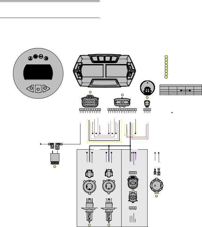
Wiring Diagram —
Hood Harness (R-XC)
(p/n 1686-856, 1686-857)
RED/BLU |
VLT/BLK |
#2 
 #1
#1
8
|
|
|
1 |
SPEEDOMETER/TACHOMETER |
|
|
|
|
|
|
2 |
CONNECTOR, MAIN HARNESS |
|
|
|
|
|
|
3 |
CONNECTOR, KEYSWITCH |
|
|
|
|
|
|
4 |
OUTLET, 12V ACCESSORY |
|
|
|
|
|
|
5 |
HEADLIGHT, LED |
|
|
|
|
|
|
6 |
HEADLIGHT, HALOGEN B |
|
|
|
|
|
|
7 |
HEADLIGHT, HALOGEN A |
|
|
|
|
|
|
8 |
ALARM, REVERSE |
|
|
|
|
|
|
|
CIRCUIT DIAGRAM" |
|
|
|
|
|
|
SWITCH |
TERMINAL |
TERMINAL |
TERMINAL |
TERMINAL |
|
C |
B |
FUNCTION |
"A" |
"B" |
"C" |
"D" |
|
OFF |
|
|
|
|
||
|
D |
A |
|
|
|
|
|
1 |
ON |
|
|
|
|
||
|
|
|
|
|
|
||
|
2 |
|
START |
|
|
|
|
|
|
|
|
|
|
|
|
|
|
3 |
|
|
|
|
|
6 |
5 |
4 |
3 |
2 |
1 |
|
|
|
|
|
|
|
1 |
|
2 |
3 |
4 |
5 |
6 |
7 |
8 |
|
|
|
|
|
|
|
|
|
|
|
|
|
|
|
|
|
|
|
|
|
|
|
|
|
|
||||||
|
|
|
|
|
|
|
|
|
|
|
|
|
|
|
|
|
|
|
|
|
|
|
|
|
D |
A |
12 |
11 |
10 |
9 |
8 |
7 |
|
|
|
|
|
|
|
9 |
|
10 11 |
|
|
|
|
|
|
|
|
C |
B |
|
|
|
|
|
|
|
|
|
|
|
|
|
|
|
12 |
13 |
14 |
15 |
16 |
|
|
|
|||||
|
|
|
|
|
|
|
|
|
|
|
|
|
|
|
|
|
|
|
||||||||
12 11 10 9 |
8 |
7 |
6 |
5 4 |
3 |
2 |
1 |
1 2 3 4 5 6 7 |
8 9 10 11 12 13 14 15 16 |
D C B A |
||||||||||||||||
| <![if ! IE]> <![endif]>(Reverse Alarm) VLT/BLK |
<![if ! IE]> <![endif]>(Can L) GRY/YEL |
<![if ! IE]> <![endif]>(Can H) WHT/GRY |
<![if ! IE]> <![endif]>(Fuel level Sensor) GRY |
<![if ! IE]> <![endif]>(Hi Beam Power) BLU |
<![if ! IE]> <![endif]>(Low Oil) BRN |
<![if ! IE]> <![endif]>(Battery (+)) RED/WHT |
<![if ! IE]> <![endif]>((-)) BLK/VLT |
<![if ! IE]> <![endif]>(Speedo/Tach Power) RED/BLU |
<![if ! IE]> <![endif]>(Low Power DC) RED/BLU |
<![if ! IE]> <![endif]>(Gauge (-)) BLK/VLT |
<![if ! IE]> <![endif]>(Battery (+)) RED/WHT |
<![if ! IE]> <![endif]>(Low Oil) BRN |
<![if ! IE]> <![endif]>(Hi Beam Power) BLU |
<![if ! IE]> <![endif]>(Fuel Level Sensor) GRY |
<![if ! IE]> <![endif]>(Can H) WHT/GRY |
|
<![if ! IE]> <![endif]>(Can L) GRY/YEL |
|
<![if ! IE]> <![endif]>(Starter Solenoid) BLK/YEL |
<![if ! IE]> <![endif]>(Keyswitch Ground) BLK/BLU |
<![if ! IE]> <![endif]>(Lo Beam Power) WHT |
<![if ! IE]> <![endif]>(Keyswitch (+)) VLT/RED |
<![if ! IE]> <![endif]>(Starter Solenoid) BLK/YEL |
<![if ! IE]> <![endif]>(Ground) BLK |
<![if ! IE]> <![endif]>(Keyswitch Ground) BLK/BLU |
<![if ! IE]> <![endif]>(Keyswitch (+)) VLT/RED |
|
|
|
HALOGEN |
|
|
|
|
LED |
|
|
|
|
|
|
HEADLIGHT |
|
|
|
HEADLIGHT |
|
|
||
| <![if ! IE]> <![endif]>BLU (Hi Beam) |
<![if ! IE]> <![endif]>WHT (Lo Beam) |
<![if ! IE]> <![endif]>BLK (Ground) |
<![if ! IE]> <![endif]>BLU (Hi Beam) |
<![if ! IE]> <![endif]>WHT (Lo Beam) |
<![if ! IE]> <![endif]>BLK (Ground) |
<![if ! IE]> <![endif]>WHT(Lo Beam Power) |
<![if ! IE]> <![endif]>BLU(Hi Beam Power) |
<![if ! IE]> <![endif]>BLK(Ground) |
<![if ! IE]> <![endif]>RED/BLU(Low Power DC) |
<![if ! IE]> <![endif]>RED/BLU (Power) |
<![if ! IE]> <![endif]>BLK (Ground) |
|
B |
|
|
B |
|
|
|
|
|
|
|
|
|
|
C |
|
A |
1 |
2 |
3 |
4 |
|
|
C |
|
A |
|
|
|
|
|
|
|
||
|
|
|
|
|
|
|
|
#1 |
|
||
|
|
|
|
|
|
|
|
|
|
#2 |
|
|
|
|
|
|
|
|
|
|
|
|
|
|
|
|
|
|
|
|
2 |
1 |
|
|
|
|
|
|
|
|
|
|
4 |
3 |
|
+ |
- |
|
|
|
|
|
|
|
|
#1 |
#2 |
||
|
C |
A |
|
C |
A |
|
|
|
|
||
|
|
|
|
|
|
|
|
||||
|
B |
|
|
B |
|
|
|
|
|
|
|
5
NOTES:
1. CONNECTORS SHOWN FROM MATING SURFACE SIDE.
2. |
BLK |
A |
INDICATES WIRE SPLICE, THIS EXAMPLE |
|
|
|
INDICATES BLK SPLICE A. |
|
4 |
3 |
|
|
|
|
4 |
|
2 |
1 |
|
1 |
2 |
3 |
4 |
| <![if ! IE]> <![endif]>Lo Beam LEDs |
<![if ! IE]> <![endif]>Hi Beam LEDs |
<![if ! IE]> <![endif]>Ground |
<![if ! IE]> <![endif]>Lighting LEDs |
|
|
|
<![if ! IE]> <![endif]>Accent |
76
0752-740
19
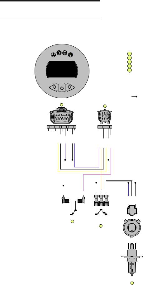
Wiring Diagram —
Hood Harness (R-SX)
(p/n 1686-880)
1
2
|
|
|
|
|
|
|
|
|
|
|
|
|
1 |
2 |
|
3 |
|
|
|
|
6 |
5 |
4 |
3 |
2 |
1 |
|
|
|
|
|
|
|
|
|
|
|
|
12 |
11 |
10 |
9 |
8 |
7 |
|
|
|
|
4 |
5 |
|
6 |
|
|
|
|
|
|
|
|
|
|
|
|
|
|
|
|
|||
12 |
11 |
10 |
9 |
8 |
7 |
6 |
5 |
4 |
3 |
2 |
1 |
1 |
2 |
3 |
4 |
5 |
6 |
|
|
|
|
<![if ! IE]> <![endif]>(CAN Lo) GRY/YEL |
<![if ! IE]> <![endif]>(CAN Hi) WHT/GRY |
|
<![if ! IE]> <![endif]>(Hi Beams) BLU |
|
|
<![if ! IE]> <![endif]>(Chassis Gnd) BLK |
<![if ! IE]> <![endif]>(Fused DC Power) RED/BLU |
<![if ! IE]> <![endif]>(Fused DC Power) RED/BLU |
<![if ! IE]> <![endif]>(Headlight Fused AC Power) YEL/VLT |
<![if ! IE]> <![endif]>(CAN Hi) WHT/GRY |
<![if ! IE]> <![endif]>(CAN Lo) GRY/YEL |
<![if ! IE]> <![endif]>(Chassis Gnd) BLK |
<![if ! IE]> <![endif]>(Warmer Switch) GRN/VLT |
|
|
|
|
|
|
|
|
|
|
|
|
|
|
|
|
|
|
|
|
|
|
|
|
|
|
|
|
|
|
|
|
|
|
|
|
|
|
|
|
|
|
|
|
|
|
|
|
|
|
|
|
|
|
|
|
|
|
|
|
|
|
|
|
|
|
|
|
|
|
|
|
|
|
|
|
|
|
|
|
|
|
|
|
|
|
|
|
|
|
|
|
|
|
|
|
|
|
|
|
|
|
|
|
|
|
|
|
|
|
|
|
|
|
|
|
|
|
|
|
|
|
|
|
|
|
|
|
|
|
|
|
|
|
|
<![if ! IE]> <![endif]>YEL/VLT |
|
|
|
|
|
|
|
|
<![if ! IE]> <![endif]>GRN/VLT |
<![if ! IE]> <![endif]>BLU |
<![if ! IE]> <![endif]>WHT |
|
||||||
|
|
<![if ! IE]> <![endif]>BLK |
|
||||||||||
|
|
|
|
|
|
|
|
|
|
|
|
|
|
#1 |
#2 |
#1 |
#3 |
|
|
||
|
|
|
#2 |
OPEN @ OFF |
|
|
|
CLOSED @ ON |
|
|
|
5 |
|
|
BLU + YEL/VLT = HI BEAMS ON |
|
|
WHT + YEL/VLT = LO BEAMS ON |
4
1CONNECTOR, SPEEDOMETER
2CONNECTOR, MAIN HARNESS
3HEADLIGHT
4SWITCH, HEADLIGHT
5SWITCH, WARMER
NOTES:
1.CONNECTORS SHOWN FROM MATING SURFACE SIDE. WHERE APPLICABLE.
2. BLK |
INDICATES WIRE SPLICE, THIS EXAMPLE |
|
INDICATES BLK SPLICE. |
| <![if ! IE]> <![endif]>(Hi Beam) |
<![if ! IE]> <![endif]>(Lo Beam) |
<![if ! IE]> <![endif]>(Grounnd) |
| <![if ! IE]> <![endif]>BLU |
<![if ! IE]> <![endif]>WHT |
<![if ! IE]> <![endif]>BLK |
|
B |
|
CA
 C A
C A
B
3
0752-739
20

Wiring Diagram —
Ignition/Main Harness
(R-XC)
(p/n 1686-833)
(Insert 0752-737 11 x 17 in color here.)

Wiring Diagram —
Ignition/Main Harness
(R-SX)
(p/n 1686-876)
(Insert 0752-738 11 x 17 in color here.)
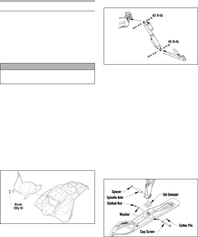
Setup Instructions
This snowmobile has been prepared at the factory to minimize required setup items; however, there are some items and inspections that must be done at a dealership or by the owner/operator. Please pay close attention to all items on the following pages. Be sure to read these instructions thoroughly before starting to set up the snowmobile.
Removing Snowmobile from Crate/ Installing Handlebar Assembly
CAUTION
Care should be taken when removing the snowmobile from the crate. Damage that is not warrantable may occur.
1.Remove the top and four sides of the crate. Remove the skis from the crate sides.
2.Remove the windshield and hardware kit.
3.Remove all mounting hardware securing the snowmobile to the crate base; then lift the snowmobile free of the crate base.
4.Swing the handlebar up and tighten the cap screws evenly to 15 ft-lb; then check steering for maximum right/left turning capabilities. Install the handlebar pad assembly.
Installing Windshield
1.Remove the protective film from the windshield.
2.Place the windshield into position on the console and secure using the six plastic rivets.
Installing Front Shock Absorbers
746-484B
1.Raise the front of the snowmobile and place it on a support stand.
2.Apply grease to the O-rings; then install the O-rings and the spherical spacers to each side of the shock eyelet spherical bearing. Take care that the O-ring is between the bearing and spherical spacers.
3.Place the upper shock into position on the frame; then install the cap screw and flange nut. Tighten to 45 ft-lb.
4.Install the lower shock eyelet into the lower A-arm mounting bracket.
5.Push the cap screw through the shock eyelet and backside of the A-arm mounting bracket; then install the nut and tighten to 45 ft-lb.
6.Install the remaining shock absorber.
Installing Skis (R-SX)
1.Slide a washer onto the cap screw used to secure the ski; then apply all-temperature grease to the shaft portion of the cap screw and spindle axle.
0752-635
0752-634
2.Install the spindle axle into the spindle; then position the ski damper into the bottom of the ski making sure the damper is properly positioned for the desired ski stance.
NOTE: The ski damper must be positioned in the ski so it is directly under the spindle.
3.With the cap screw hole of the ski centered with the spindle axle, slide the cap screw with washer through the outside of the ski and spindle assemblies.
25
Loading...