


 Loading...
9000 SERVICE MANUAL
<![if ! IE]><![endif]>2022
P/N-2263-296
Table of Contents
General Information/Foreword .................................................. |
2 |
Snowmobile Identification ..................................................... |
2 |
Recommended Gasoline and Oil .......................................... |
2 |
Engine Break-In .................................................................... |
2 |
Drive Belt Break-In................................................................ |
3 |
Genuine Parts ....................................................................... |
3 |
Varying Altitude Operation..................................................... |
3 |
Preparation for Storage......................................................... |
4 |
Preparation after Storage...................................................... |
4 |
After Break-In Checkup/Checklist ......................................... |
5 |
Engine Specifications............................................................ |
5 |
Electrical Specifications ........................................................ |
6 |
Drive System Specifications ................................................. |
6 |
Drive Clutch/Driven Clutch-Related Specifications ............... |
6 |
Drive System Components ................................................... |
6 |
Chain Case Performance Calibrations.................................. |
7 |
Track Specifications .............................................................. |
7 |
IFP Shock Specifications ...................................................... |
7 |
Torque Conversions .............................................................. |
8 |
Torque Specifications............................................................ |
8 |
Steering and Body ...................................................................... |
9 |
Steering Post (Non-EPS) ...................................................... |
9 |
Steering Post (EPS)............................................................ |
10 |
Ski ....................................................................................... |
11 |
Ski Wear Bar ....................................................................... |
12 |
Spindle ................................................................................ |
12 |
Steering Tie Rod ................................................................. |
13 |
Ski Alignment ...................................................................... |
14 |
A-Arms ................................................................................ |
15 |
Ski Shock Absorber............................................................. |
17 |
Sway Bar............................................................................. |
17 |
Front Bumper ...................................................................... |
18 |
Seat Assembly .................................................................... |
18 |
Seat Cushion ...................................................................... |
18 |
Taillight/Brake Light Assembly ............................................ |
18 |
Rear Bumper/Snowflap....................................................... |
19 |
Windshield/Console/ Headlight ........................................... |
19 |
Adjusting Headlight Aim ..................................................... |
20 |
Engine........................................................................................ |
21 |
Engine Removing/Installing ................................................ |
21 |
Engine Servicing ................................................................. |
29 |
Assembly Schematic........................................................... |
50 |
Troubleshooting Engine ...................................................... |
52 |
Engine-Related Items ............................................................... |
54 |
Water Pump ........................................................................ |
54 |
Pressure Testing Engine ..................................................... |
56 |
Checking Compression....................................................... |
56 |
Changing Oil/Filter .............................................................. |
56 |
Liquid Cooling System ........................................................ |
57 |
Cooling System Schematic ................................................. |
58 |
Heat Exchanger .................................................................. |
59 |
Air Silencer.......................................................................... |
60 |
Turbocharger/Intercooler..................................................... |
61 |
Fuel Systems............................................................................. |
65 |
Fuel System ........................................................................ |
65 |
Individual Components........................................................ |
65 |
Self-Diagnostic System/Codes............................................ |
67 |
Fuel Pressure Regulator ..................................................... |
68 |
Throttle Cable...................................................................... |
68 |
Fuel Pump........................................................................... |
68 |
Gas Tank ............................................................................. |
70 |
Electrical Systems .................................................................... |
71 |
Ignition System.................................................................... |
71 |
Electronic Power Steering (EPS) ........................................ |
71 |
Throttle Position Sensor...................................................... |
76 |
Electrical Resistance Tests ................................................. |
77 |
Voltage Regulator Tests ...................................................... |
78 |
Testing Fuel Gauge Sender ................................................ |
78 |
Emergency Stop Switch ...................................................... |
78 |
Starter Relay Solenoid ........................................................ |
78 |
Fuse .................................................................................... |
79 |
Ignition Switch..................................................................... |
79 |
Starter Motor ....................................................................... |
79 |
Troubleshooting Electric Start ............................................. |
82 |
Magneto .............................................................................. |
82 |
Brake Light Switch .............................................................. |
84 |
Testing Headlight Dimmer Switch ....................................... |
84 |
Testing Handlebar Warmer Elements ................................ |
84 |
Testing Thumb Warmer Element......................................... |
85 |
Testing Handlebar Warmer/Thumb Warmer Switch ............ |
85 |
Testing Seat Heater Switches ............................................. |
85 |
Testing Speedometer Sensor.............................................. |
86 |
Testing Gear Position Switch .............................................. |
86 |
Testing Shift Switch ............................................................. |
86 |
Testing Shift Actuator .......................................................... |
86 |
Drivetrain/Track/Brake Systems .............................................. |
87 |
Drive Belt............................................................................. |
87 |
Drive Clutch......................................................................... |
87 |
Driven Clutch....................................................................... |
94 |
Drive Clutch/Driven Clutch .................................................. |
96 |
Drivetrain............................................................................. |
97 |
Drive Sprockets................................................................. |
101 |
Track Tension.................................................................... |
103 |
Track Alignment ................................................................ |
104 |
Brake System.................................................................... |
104 |
Brake Lever/Master Cylinder Assembly ............................ |
109 |
Troubleshooting Drive Clutch/Driven Clutch ..................... |
110 |
Troubleshooting Track........................................................ |
111 |
Troubleshooting Hydraulic Brake System .......................... |
111 |
Suspension.............................................................................. |
112 |
Suspension Setup Basics ................................................. |
112 |
Chassis and Skid Frame Mounting Locations................... |
116 |
Servicing Suspension........................................................ |
117 |
Servicing IFP Shock.......................................................... |
123 |
1
General
Information/Foreword
NOTE: General specifications for each 2022 Arctic
Cat Snowmobile can be accessed from the Arctic Cat Cat Tracker Dealer Communication System.
NOTE: Some illustrations and photographs used in this manual are used for clarity purposes only and are not designed to depict actual conditions.
This Service Manual contains service and maintenance information for 2022 Arctic Cat ZR 9000 Thundercat snowmobile models. The manual is designed to aid service personnel in service-oriented applications.
This manual is divided into sections that cover specific snowmobile components or systems and, in addition to the standard service procedures, include assembling, disassembling, and inspecting instructions. When using this manual as a guide, the technician should use discretion as to how much disassembly is needed to correct any given condition.
The service technician should become familiar with the operation and construction of the components or systems by carefully studying the complete manual. This will assist the service technician in becoming more aware of and efficient with servicing procedures. Such efficiency not only helps build consumer confidence but also saves time and labor.
All Arctic Cat publications and snowmobile decals dis-
play the words Warning, Caution, and Note to emphasize important information. The symbol ! WARNING
identifies personal safety-related information. Be sure to
follow the directive because it deals with the possibility of severe personal injury or even death. A CAUTION
identifies unsafe practices which may result in snowmo- bile-related damage. Follow the directive because it deals with the possibility of damaging part or parts of the snowmobile. The symbol NOTE: identifies supplementary information worthy of particular attention.
At the time of publication, all information, photographs, and illustrations were technically correct. Some photographs and illustrations used in this manual are used for clarity purposes only and are not designed to depict actual conditions. Because Arctic Cat Inc. constantly refines and improves its products, no retroactive obligation is incurred.
All materials and specifications are subject to change without notice.
Product Service and Warranty Department Arctic Cat Inc.
Snowmobile Identification
The Arctic Cat Snowmobile has two important identification numbers. The Vehicle Identification Number (VIN) is stamped into the tunnel near the right-side footrest or on top of the tunnel. The decal also displays pertinent production information. The Engine Serial Number (ESN) is stamped into the crankcase of the engine.
These numbers are required to complete warranty claims properly. No warranty will be allowed by Arctic Cat if the engine serial number or VIN is removed or mutilated in any way.
Recommended Gasoline
and Oil
CAUTION
Do not use white gas or gasoline containing methanol. Only Arctic Cat-approved gasoline additives should be used.
RECOMMENDED GASOLINE
The recommended gasoline to use in these snowmobiles is 87 octane regular unleaded. In many areas, oxygenates are added to the gasoline. Oxygenated gasolines containing up to 10% ethanol are acceptable gasolines.
When using ethanol-blended gasoline, adding a gasoline antifreeze is not necessary since ethanol will prevent the accumulation of moisture in the fuel system.
RECOMMENDED OIL
CAUTION
Any oil used in place of the recommended oil may cause serious damage.
The recommended oil to use is Synthetic C-TEC4 Oil (p/n 6639-529 — gal.). After the engine break-in period, the engine oil and filter should be changed every 2500 miles (4000 km) or before prolonged storage.
Engine Break-In
The engine (when new or rebuilt) requires a short break-in period before the engine is subjected to heavy load conditions.
This engine does not require any pre-mixed fuel during the break-in period.
There is never a more important period in the life of the engine than the first 300 miles (500 km).
Since the engine is brand new, do not put an excessive load on it for the first 300 miles (500 km). The various parts in the engine wear and polish themselves to the correct operating clearances. During this period, prolonged full throttle operation or any condition that might result in engine overheating must be avoided.
2

Operating your snowmobile for the first time: Start the engine and let it idle for 15 minutes.
0-100 miles (0-160 km): Avoid prolonged operation above 6000 RPM.
100-300 miles (160-500 km): Avoid prolonged operation above 8000 RPM.
300 miles (500 km) and beyond: The snowmobile can now be operated normally.
NOTE: After 500 miles (800 km) of operation, the engine oil must be changed and the oil filter replaced. If any engine trouble should occur during the engine break-in period, immediately have an Arctic Cat dealer check the snowmobile.
Drive Belt Break-In
Drive belts require a break-in period of 25 miles (40 km). Drive the snowmobile for 25 miles (40 km) at 3/4 throttle or less. By revving the engine up and down (but not exceeding 60 mph [97 km/h]), the exposed cord on the side of a new belt will be worn down. This will allow the drive belt to gain its optimum flexibility and will extend drive belt life.
NOTE: Before starting the snowmobile in extremely cold temperatures, the drive belt should be removed and warmed up to room temperature. Once the drive belt is at room temperature, install the drive belt (see Drive Belt sub-section in the Drivetrain/Track/Brake Systems section of this manual).
CAUTION
Running the engine with the drive belt removed could result in serious engine damage and drive clutch failure.
Genuine Parts
When replacement of parts is necessary, use only genuine Arctic Cat parts. They are precision-made to ensure high quality and correct fit.
Varying Altitude Operation
Operating a snowmobile at varying altitudes requires recalibration of drive system components.
Consult the appropriate specification sheet on Cat Tracker Online.
Following are basic altitude theories for suspension:
SUSPENSION
The different riding styles of the individual operator, the varying snow conditions, and the type of terrain are all factors that affect the suspension at high altitude. Trail riding versus powder snow riding versus combination riding will all require different suspension settings.
The normal setting for front ski suspension is as little spring preload tension as possible for powder snow riding allowing the skis to float across the snow with the least amount of resistance. Trail riding will require more spring tension to carry the varying load more effectively. Many different settings and spring tensions to consider exist when adjusting for riding style and snow conditions.
The rear suspension has a number of spring settings that produce different riding characteristics.
The front arm spring and shock will also affect the ride and handling when either on a trail or in powder snow. A strong spring setting on this shock will cause the snowmobile to tend to “dig” more when riding in the powder snow rather than climbing up on top of the snow. But, it will work more effectively when riding on a trail. A softer spring setting will allow the front of the rear suspension to collapse much quicker and change the angle of the track to the snow. A more gradual angle will tend to raise the snowmobile up on the snow rather than digging into it.
Many possible variables and adjustments to the rear suspension exist depending on snow conditions, riding style, and type of terrain. These adjustments can be made to individualize the snowmobile to the riding style of the operator.
As snow cover and riding conditions change, several different adjustments can be made to change the ride and handling characteristics for operator preference. Located on the front suspension arm are limiter straps. They limit the amount of “fallout” the front arm can have. These straps may be adjusted in or out due to conditions and riding style. The more the straps are brought up, the more steering power the operator has due to the amount of ski pressure.
Another adjustment that can be made on the rear suspension is the front arm shock spring tension. As trail conditions change, the spring preload may be used to decrease the chance of the front end “bottoming out.” With a stiffer spring preload, the ride of the snowmobile will improve on the trail but will affect the performance in the deep powder snow. In deep powder snow, the stiffer spring preload will cause the front-end to “dig” and possibly take longer for it to plane off. Several different-rate springs are available for different riding styles and terrain conditions.
On the standard models, the front shock springs are also individually adjustable for the terrain conditions and driving style of the operator. The spring adjuster has been set at the factory so the correct amount of threads are exposed between the spring adjuster and the shock housing as an initial setting. Additional ski pressure can be obtained by tightening the spring tension; ski pressure can be decreased by relaxing spring tension. Springs with different spring rates are available for operator choice and snow conditions.
3

A limit exists as to how far you can preload the springs before “coil bind” takes effect where the wire on the spring actually runs into itself and causes binding. Equal adjustments should be maintained on both sides of the snowmobile. Finally, track tension should be looked at to make sure that it is within recommended specifications to affect the efficiency of the snowmobile. On models with the torque sensing link, the track is actually tightening as the suspension moves through its range of motion causing the track to sag in the middle and rub on the top part of the rear suspension arm.
Preparation for Storage
Prior to storing the snowmobile, it must be properly serviced to prevent corrosion and component deterioration.
1.Clean the seat cushion with a damp cloth and Arctic Cat Vinyl Protectant.
2.Clean the snowmobile thoroughly by hosing dirt, oil, grass, and other foreign matter from the skid frame, tunnel, hood, and belly pan. Allow the snowmobile to dry thoroughly. DO NOT get water into any part of the engine.
3.Fill the gas tank to its rated capacity; then add Arctic Cat Fuel Stabilizer to the gas tank following directions on the container for the stabilizer/gasoline ratio. Tighten the gas tank cap securely.
4.With the snowmobile level, check the lubricant level in the chain case. If low, add chain lube through the fill plug hole.
5.Remove the drive belt from the drive clutch/driven clutch. Lay the belt on a flat surface or slide it into a cardboard sleeve to prevent warping or distortion during storage; then clean and inspect the drive clutch and driven clutch.
6.Apply light oil to the upper steering post bushings and to the shafts of the shock absorbers; then lubricate the rear suspension with a low-temperature grease.
7.Tighten all nuts, bolts, and cap screws making sure all calibrated nuts, bolts, and cap screws are tightened to specifications. Make sure all rivets holding the components together are tight. Replace all loose rivets.
8.Clean and polish the hood, console, and chassis with Cat Cleaner. DO NOT USE SOLVENTS. THE PROPELLENT WILL DAMAGE THE FINISH.
9.Disconnect the battery cables making sure to disconnect the negative cable first; then clean the battery posts and cables.
CAUTION
Sealed batteries require charging if left for extended non-start periods. Arctic Cat recommends trickle charging once a month. Follow the manufacturer’s instructions and cautions.
10.If possible, store the snowmobile indoors. Raise the track off the floor by blocking up the back end making sure the snowmobile is secure. Loosen the track adjusting bolts to reduce track tension. Cover the snowmobile with a machine cover or a heavy, ventilated tarpaulin to protect it from dirt and dust.
11.If the snowmobile must be stored outdoors, position the snowmobile out of direct sunlight; then block the entire snowmobile off the ground making sure the snowmobile is secure. Loosen the track adjusting bolts to reduce track tension. Cover with a machine cover or a heavy, ventilated tarpaulin to protect it from dirt, dust, and rain.
CAUTION
Avoid storing in direct sunlight and using a plastic cover as moisture may collect on the snowmobile causing corrosion.
Preparation after Storage
Taking the snowmobile out of storage and correctly preparing it for another season will ensure many miles and hours of trouble-free snowmobiling. Arctic Cat recommends the following procedure:
1.Clean the snowmobile thoroughly. Polish the exterior of the snowmobile.
2.Clean the engine. Remove the cloth from the exhaust system. Check exhaust system and air silencer for obstructions.
3.Inspect all control wires and cables for signs of wear or fraying. Replace if necessary. Use cable ties or tape to route wires and cables away from hot or rotating parts.
4.Inspect the drive belt for cracks and tears. Check belt specifications. Replace if damaged or worn. Install the drive belt (see the Drivetrain/Track/Brake Systems section).
NOTE: If the old belt is worn but in reasonable condition, retain it with the snowmobile as a spare in case of emergency.
5.Adjust the throttle cable. Inspect all fuel hoses and oil hoses for deterioration or cracks; replace if necessary. Make sure all connections are tight.
6.Tighten all nuts, bolts, and cap screws making sure all calibrated nuts, bolts, and cap screws are tightened to specifications.
7.If not done during preparation for storage, lubricate the rear suspension with a low-temperature grease.
8.Check the coolant level and all coolant hoses and connections for deterioration or cracks. Add properly mixed coolant as necessary.
9.Charge the battery; then connect the battery cables making sure to connect the positive cable first. Test the electric start system.
4

10.Inspect the entire brake system, all controls, headlight, taillight, brake light, ski wear bars, and headlight aim; adjust or replace as necessary.
11.Adjust the track to the proper tension and alignment.
After Break-In
Checkup/Checklist
Certain areas require adjustment after the break-in period in order to obtain peak performance. These areas are the following:
DRIVE CLUTCH/DRIVEN CLUTCH ALIGNMENT — The alignment between the drive clutch and driven clutch are set at the factory. Normally, no adjustment is necessary; however, if premature drive belt wear or poor performance is experienced, the drive clutch/driven clutch alignment must be checked.
TRACK TENSION AND ALIGNMENT — A certain amount of stretch occurs on all tracks during the first 500 miles (800 km). The track must be inspected/adjusted after the first 50 to 100 miles (80 to 160 km) to the specifications given in the Track Specifications sub-section of this section and periodically thereafter. If these adjustments aren’t performed, the track may “derail” which leads to track and slide rail damage.
Along with these major areas, other areas should be checked and adjusted.
Below is a list of items to check after the break-in period. The recommended mileage for this inspection is between 100 and 300 miles (160 and 500 km).
Check drive clutch/driven clutch alignment Adjust track tension and alignment
Check throttle cable tension Check engine idle
Check coolant level
Check chain case lubricant level Check engine oil
Check and adjust chain tension (free-play) Check lights (high/low beam, brake light) Check safety switch operation
Check engine compartment for any rubbing components
Check steering hardware for tightness
Check skid frame and A-arm mounting hardware for tightness
Check brake lever travel and adjustment Grease all lubrication points
Engine Specifications
9000
ITEM |
|
|
|
Engine Model Number |
|
|
8KJ |
Displacement |
|
|
998 cc |
Compression Ratio |
|
|
9.0:1 |
Bore x Stroke |
|
|
80.0 x 66.2 mm (3.15 × 2.61 in.) |
Cooling System |
|
|
Liquid |
Spark Plug (NGK) |
|
|
CR8E |
Spark Plug Gap |
|
|
0.71-0.79 mm (0.028-0.031 in.) |
Piston Skirt/Cylinder Clearance |
|
0.036-0.061 mm |
|
|
|
|
(0.0014-0.0024 in.) |
Piston Pin Diameter |
|
|
20.990-20.995 mm |
|
|
|
(0.8264-0.8266 in.) |
Piston Pin Bore Diameter |
|
21.004-21.015 mm |
|
|
|
|
(0.8269-0.8274 in.) |
Piston Pin to Piston Pin Bore Clearance |
0.009-0.025 mm |
||
|
|
|
(0.0003-0.0009 in.) |
Connecting Rod: Small End Diameter |
21.005-21.027 mm |
||
|
|
|
(0.8269-0.8278 in.) |
Crankshaft Pin/Connecting Rod: Big End |
0.030-0.048 mm |
||
Clearance |
|
|
(0.0012-0.0019 in.) |
Connecting Rod: Big End Diameter |
41.000-41.018 mm |
||
|
|
|
(1.6142-1.6149 in.) |
Piston Ring End Gap |
|
(Top) |
0.35-0.45 mm (0.014-0.018 in.) |
|
|
(2nd) |
0.75-0.85 mm (0.030-0.033 in.) |
|
|
(Oil) |
0.10-0.35 mm (0.004-0.014 in.) |
Piston Ring/Groove Clearance |
(1st/Top) |
0.030-0.065 mm |
|
|
|
(2nd) |
(0.0012-0.0026 in.) |
|
|
0.020-0.055 mm |
|
|
|
(Oil) |
(0.0008-0.0022 in.) |
|
|
0.040-0.140 mm |
|
|
|
|
(0.0016-0.0055 in.) |
Piston Diameter (10 mm from bottom |
79.95-79.96 mm |
||
edge) |
|
|
(3.1476-3.1480 in.) |
Cam Lobe Height |
|
(Intake) |
33.750-33.850 mm |
|
|
(Exhaust) |
(1.3287-1.3327 in.) |
|
|
33.750-33.850 mm |
|
|
|
|
(1.3287-1.3327 in.) |
Cam Lobe Width (Intake/Exhaust) |
24.950-25.050 mm |
||
|
|
|
(0.9823-0.9862 in.) |
Camshaft Journal Diameter |
|
24.46-24.47 mm |
|
|
|
|
(0.9630-0.9635 in.) |
Camshaft Journal Clearance |
|
0.028-0.062 mm |
|
|
|
|
(0.0011-0.0024 in.) |
Crank Pin Diameter |
|
|
37.976-38.000 mm |
|
|
|
(1.4951-1.4961 in.) |
Crankshaft Runout (max) |
|
0.3 mm (0.012 in.) |
|
Crankshaft Main Bearing Clearance |
0.027-0.045 mm |
||
|
|
|
(0.0011-0.0018 in.) |
Crankshaft/Rod Bearing Clearance |
0.030-0.048 mm |
||
|
|
|
(0.0012-0.0019 in.) |
Valve Clearance — Cold |
(Intake) |
0.15-0.22 mm (0.0059-0.0087 in.) |
|
|
|
(Exhaust) |
0.21-0.25 mm (0.0083-0.098 in.) |
Valve Stem Diameter |
|
(Intake) |
4.475-4.490 mm |
|
|
(Exhaust) |
(0.1762-0.1677 in.) |
|
|
4.460-4.475 mm |
|
|
|
|
(0.1756-0.1762 in.) |
Valve Guide Inside Diameter |
(Intake) |
4.500-4.512 mm |
|
|
|
(Exhaust) |
(0.1772-0.1776 in.) |
|
|
4.500-4.512 mm |
|
|
|
|
(0.1772-0.1776 in.) |
Valve Guide/Stem Clearance |
(Intake) |
0.010-0.037 mm |
|
|
|
(Exhaust) |
(0.0004-0.0015 in.) |
|
|
0.025-0.052 mm |
|
|
|
|
(0.0010-0.0020 in.) |
Valve Face Width |
(Intake/Exhaust) |
0.90-1.10 mm (0.035-0.043 in.) |
|
|
VALVE TIMING |
||
Intake Open (BTDC) |
|
|
35.0 degrees |
Intake Closed (ABDC) |
|
|
45.0 degrees |
Exhaust Open (BBDC) |
|
|
45.0 degrees |
Exhaust Closed (ATDC) |
|
|
35.0 degrees |
Valve Overlap |
|
|
70.0 degrees |
5

Electrical Specifications
(Normally Closed Ignition)
Component |
Test Value |
|
+ Test Connections - |
|
Magneto Coil (3 tests)* |
0.15-0.23 ohm |
white |
|
white |
Primary Ignition Coil* |
1.19-1.61 ohms |
|
|
|
Secondary Ignition Coil* |
8500-11,500 ohms |
|
|
|
Crankshaft Position Sensor |
336-504 ohms |
blue/white |
|
green/white |
Voltage Regulator/Rectifier* |
12-14.5 DC Volts |
terminal |
|
terminal |
Magneto Coil (no load) |
36-44 AC Volts |
white |
|
white |
Ignition Switch |
Less than 1 ohm (key in ON position) |
terminal |
|
terminal |
* Harness plugged in
NOTE: Lighting coil output is unregulated voltage.
! WARNING
Most voltages generated by the ignition system are sufficient to interrupt pacemakers! All technicians, especially those using pacemakers, must avoid contact with all electrical connections when pulling the recoil starter rope or after the engine has been started.
Drive System
Specifications
Model |
Altitude |
Drive Clutch |
Cam Arm |
Driven |
Torque |
Drive |
Engagement |
Peak |
Top |
Bottom |
Chain |
Clutch |
|||||||||||
|
|
Spring |
|
Spring |
Bracket |
Belt |
RPM |
RPM |
Gear |
Gear |
Pitch |
|
|
|
|
|
|
|
|
|
|
|
|
ZR 9000 Thundercat |
n/a |
120/285 lb |
J14-74g |
155-220 lb |
58-49-.15 |
0627-112 |
4-4200 |
8750 |
24T |
50T |
92 |
ZR 9000 Thundercat (OS) |
n/a |
120/285 lb |
J14-74g |
155-220 lb |
58-49-.15 |
0627-112 |
4-4200 |
8750 |
22T |
48T |
90 |
Drive Clutch/Driven
Clutch-Related
Specifications
ALIGNMENT BAR
Offset P/N |
Center-to-Center |
Offset |
Float |
0744-097 |
10.38” ± 0.020” |
1.500” |
None |
|
(263.7 mm ± 0.5 mm) |
(38.1 mm) |
|
Drive System Components
A list of drive system components that are available through the Arctic Cat Service Parts Department can be found in the POGA Reference Guide. This information will be useful when doing any fine-tuning on the drive system.
6
Chain Case Performance
Calibrations
Drive |
Gear |
Ratio Chain |
|
|
|
|
|
|
Engine RPM |
|
|
|
|
|
|
|||||
Sprocket |
Ratio |
|
|
|
|
|
|
|
|
|
|
|
|
|||||||
|
|
|
|
|
|
|
|
|
|
|
|
|
|
|
|
|
|
|||
|
Top |
Btm |
|
|
6200 |
6400 |
6600 |
6800 |
7000 |
7200 |
7400 |
7600 |
7800 |
|
8000 |
8200 |
8400 |
8600 |
8800 |
9000 |
|
|
|
|
|
|
|
|
|
Vehicle Speed (mph) |
|
|
|
|
|
|
|||||
|
|
|
|
|
|
|
|
|
|
|
|
|
|
|
|
|
||||
9 Tooth |
21 |
49 |
0.429 |
90 |
73 |
75 |
77 |
80 |
82 |
84 |
87 |
89 |
91 |
|
94 |
96 |
98 |
101 |
103 |
105 |
(2.86" |
20 |
46 |
0.435 |
88 |
74 |
76 |
78 |
81 |
83 |
85 |
88 |
90 |
93 |
|
95 |
97 |
100 |
102 |
104 |
107 |
pitch) |
|
|||||||||||||||||||
23 |
51 |
0.451 |
92 |
76 |
79 |
81 |
84 |
86 |
89 |
91 |
94 |
96 |
|
98 |
101 |
103 |
106 |
108 |
111 |
|
|
|
|||||||||||||||||||
|
22 |
48 |
0.458 |
90 |
78 |
80 |
83 |
85 |
88 |
90 |
93 |
95 |
98 |
|
100 |
103 |
105 |
108 |
110 |
113 |
|
24 |
50 |
0.480 |
92 |
81 |
84 |
86 |
89 |
92 |
94 |
97 |
100 |
102 |
|
105 |
107 |
110 |
113 |
115 |
118 |
|
21 |
41 |
0.512 |
86 |
87 |
89 |
92 |
95 |
98 |
101 |
103 |
106 |
109 |
|
112 |
115 |
117 |
120 |
123 |
126 |
|
21 |
38 |
0.553 |
84 |
93 |
97 |
100 |
103 |
106 |
109 |
112 |
115 |
118 |
|
121 |
124 |
127 |
130 |
133 |
136 |
|
20 |
35 |
0.571 |
82 |
97 |
100 |
103 |
106 |
109 |
112 |
115 |
118 |
122 |
|
125 |
128 |
131 |
134 |
137 |
140 |
|
23 |
40 |
0.575 |
86 |
97 |
100 |
104 |
107 |
110 |
113 |
116 |
119 |
122 |
|
126 |
129 |
132 |
135 |
138 |
141 |
|
22 |
37 |
0.595 |
84 |
101 |
104 |
107 |
110 |
114 |
117 |
120 |
123 |
127 |
|
130 |
133 |
136 |
140 |
143 |
146 |
|
24 |
39 |
0.615 |
86 |
104 |
107 |
111 |
114 |
118 |
121 |
124 |
128 |
131 |
|
134 |
138 |
141 |
144 |
148 |
151 |
|
23 |
36 |
0.639 |
84 |
108 |
112 |
115 |
119 |
122 |
126 |
129 |
132 |
136 |
|
139 |
143 |
146 |
150 |
153 |
157 |
|
24 |
35 |
0.686 |
84 |
116 |
120 |
123 |
127 |
131 |
135 |
138 |
142 |
146 |
|
150 |
153 |
157 |
161 |
165 |
168 |
Track Specifications IFP Shock Specifications
Model |
Length |
Lug Height |
ZR 9000 Thundercat |
137” (3480 mm) |
1.25” (31.75 mm) |
|
|
1.75” (44.5 mm) |
NOTE: The track tension should be 20 lb @ 2 in. (9 kg
@ 50.8 mm).
Below is a list of IFP shock absorbers used on the front and rear suspensions of Arctic Cat snowmobiles. If replacing a shock absorber, always select a shock absorber with the same length, both collapsed and extended.
FRONT ARM
Model |
Collapsed |
Extended |
Stroke |
Piston |
|
Length |
Length |
Depth |
|||
|
|
||||
ZR 9000 Thundercat |
8.55” |
12.49” |
3.94” |
4.90” |
(217.2 mm) (317.2 mm) (100.1 mm) (124.5 mm)
7

Torque Conversions
ft-lb |
N-m |
ft-lb |
N-m |
ft-lb |
N-m |
ft-lb |
N-m |
1 |
1.4 |
26 |
35.4 |
51 |
69.4 |
76 |
103.4 |
2 |
2.7 |
27 |
36.7 |
52 |
70.7 |
77 |
104.7 |
3 |
4.1 |
28 |
38.1 |
53 |
72.1 |
78 |
106.1 |
4 |
5.4 |
29 |
39.4 |
54 |
73.4 |
79 |
107.4 |
5 |
6.8 |
30 |
40.8 |
55 |
74.8 |
80 |
108.8 |
6 |
8.2 |
31 |
42.2 |
56 |
76.2 |
81 |
110.2 |
7 |
9.5 |
32 |
43.5 |
57 |
77.5 |
82 |
111.5 |
8 |
10.9 |
33 |
44.9 |
58 |
78.9 |
83 |
112.9 |
9 |
12.2 |
34 |
46.2 |
59 |
80.2 |
84 |
114.2 |
10 |
13.6 |
35 |
47.6 |
60 |
81.6 |
85 |
115.6 |
11 |
15 |
36 |
49 |
61 |
83 |
86 |
117 |
12 |
16.3 |
37 |
50.3 |
62 |
84.3 |
87 |
118.3 |
13 |
17.7 |
38 |
51.7 |
63 |
85.7 |
88 |
119.7 |
14 |
19 |
39 |
53 |
64 |
87 |
89 |
121 |
15 |
20.4 |
40 |
54.4 |
65 |
88.4 |
90 |
122.4 |
16 |
21.8 |
41 |
55.8 |
66 |
89.8 |
91 |
123.8 |
17 |
23.1 |
42 |
57.1 |
67 |
91.1 |
92 |
125.1 |
18 |
24.5 |
43 |
58.5 |
68 |
92.5 |
93 |
126.5 |
19 |
25.8 |
44 |
59.8 |
69 |
93.8 |
94 |
127.8 |
20 |
27.2 |
45 |
61.2 |
70 |
95.2 |
95 |
129.2 |
21 |
28.6 |
46 |
62.6 |
71 |
96.6 |
96 |
130.6 |
22 |
29.9 |
47 |
63.9 |
72 |
97.9 |
97 |
131.9 |
23 |
31.3 |
48 |
65.3 |
73 |
99.3 |
98 |
133.3 |
24 |
32.6 |
49 |
66.6 |
74 |
100.6 |
99 |
134.6 |
25 |
34 |
50 |
68 |
75 |
102 |
100 |
136 |
Torque Specifications
NOTE: Always use new hardware when replacing a cap screw that has patch-lock applied, or a nylon nut or lock nut.
Torque |
Tolerance |
0-15 ft-lb (0-20.3 N-m) |
±20% |
16-39 ft-lb (21.7-52.9 N-m) |
±15% |
40+ ft-lb (54.2+ N-m) |
±10% |
Item |
Secured to |
Torque |
|
ft-lb |
|||
|
|
||
DRIVE |
SYSTEM |
|
|
Drive Clutch |
Engine |
51 |
|
Drive Clutch Cover |
Movable Sheave |
120 in.-lb |
|
Cam Arm Lock Nut |
Cam Arm Screw |
50 in.-lb |
|
Driven Clutch |
Driven Shaft |
60 |
|
Movable Sheave |
Torque Bracket |
120 in.-lb |
|
Chain Case (Cap Screw) |
Chassis |
10 |
|
Chain Case (Torx-Head Screw) |
Chassis |
13 |
|
Chain Case Cover |
Chain Case |
9 |
|
Shift Actuator |
Chain Case Cover |
36 in.-lb |
|
Brake Caliper |
Chassis |
25 |
|
Outside Caliper Housing |
Inside Caliper Housing |
25 |
|
Brake Line |
Caliper |
25 |
|
Brake Line |
Master Cylinder |
25 |
|
Brake Caliper |
Shield Cover |
96 in.-lb |
|
STEERING/FRONT |
SUSPENSION/CHASSIS |
|
|
Ski |
Spindle |
35 |
|
Ski |
Wear Bar |
15 |
|
Ski |
Ski Handle |
54 in.-lb |
|
Riser Block Cap |
Riser Block |
20 |
|
Steering Support |
Mounting Block |
8 |
|
Steering Post |
Steering Stop Bracket |
55 |
|
Steering Tie Rod |
Steering Arm |
20 |
|
Steering Tie Rod |
Steering Post |
55 |
|
Tie Rod |
Steering Arm |
20 |
|
Tie Rod |
Spindle Arm |
32 |
|
Steering Arm |
Chassis |
8 |
|
A-Arm (Upper) |
Chassis |
20 |
|
A-Arm (Lower) |
Chassis (Front) |
65 |
|
A-Arm (Lower) |
Chassis (Rear) |
45 |
|
A-Arm (Upper) |
Spindle |
23 |
|
A-Arm (Lower) |
Spindle |
45 |
|
Shock Absorber |
Spindle |
32 |
|
Shock Absorber |
Chassis |
32 |
|
Sway Bar Link |
A-Arm/Sway Bar Link |
23 |
|
Sway Bar Mounting Bracket |
Chassis |
9 |
|
REAR |
SUSPENSION |
|
|
Wear Strip |
Rail |
50 in.-lb |
|
End Cap |
Rail |
80 in.-lb |
|
Mounting Block |
Rail |
12 |
|
Rear Arm |
Rail |
45 |
|
Rear Arm |
Idler Arm |
55 |
|
Spring Slide |
Rail |
20 |
|
Front Arm |
Rail |
52 |
|
Coupler Block Axle |
Rail |
40 |
|
Limiter Strap |
Rail Support |
72 in.-lb |
|
Rear Wheel Axle |
Rail |
34 |
|
Skid Frame |
Tunnel |
45 |
|
Front Shock |
Rail |
50 |
|
Rail Support |
Rail |
20 |
|
Limiter Strap |
Front Arm |
72 in.-lb |
8
Steering and Body
This section has been organized into sub-sections for servicing steering and body components; however, some components may vary from model to model. The technician should use discretion and sound judgment when removing and installing components.
NOTE: Whenever a part is worn excessively, cracked, or damaged in any way, replacement is necessary.
SPECIAL TOOLS
A special tool must be available to the technician when servicing the steering and body systems.
NOTE: When indicated for use, each special tool will be identified by its specific name, as shown in the chart below, and capitalized.
Description |
p/n |
|
|
Handlebar Stand |
5639-152 |
|
|
Steering Post Stand |
5639-946 |
|
|
NOTE: Special tools are available from the Arctic
Cat Service Parts Department.
Steering Post (Non-EPS)
REMOVING
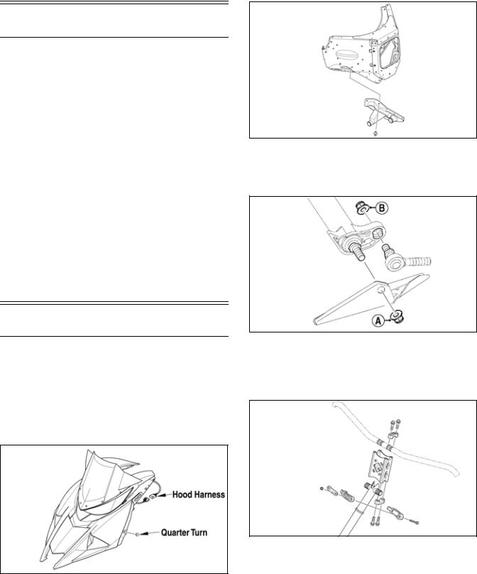
1.Rotate the two quarter-turns to the vertical position; then pull the top of the side panel out and up and off the skid plate.
2.Disconnect the hood harness on the left-side of the hood; then loosen the two quarter-turns securing the front of the hood. Pull the hood forward and remove the hood.
0750-565A
3.Remove the push rivets securing the right-side steering boot to the chassis. This allows access to the two nuts securing the bottom of the steering post.
SNO-763
4.Remove the nut (A) securing the bottom of the existing steering post to the steering stop bracket; then remove the nut (B) securing the steering tie rod assembly to the steering post. Discard both nuts.
SNO-2221A
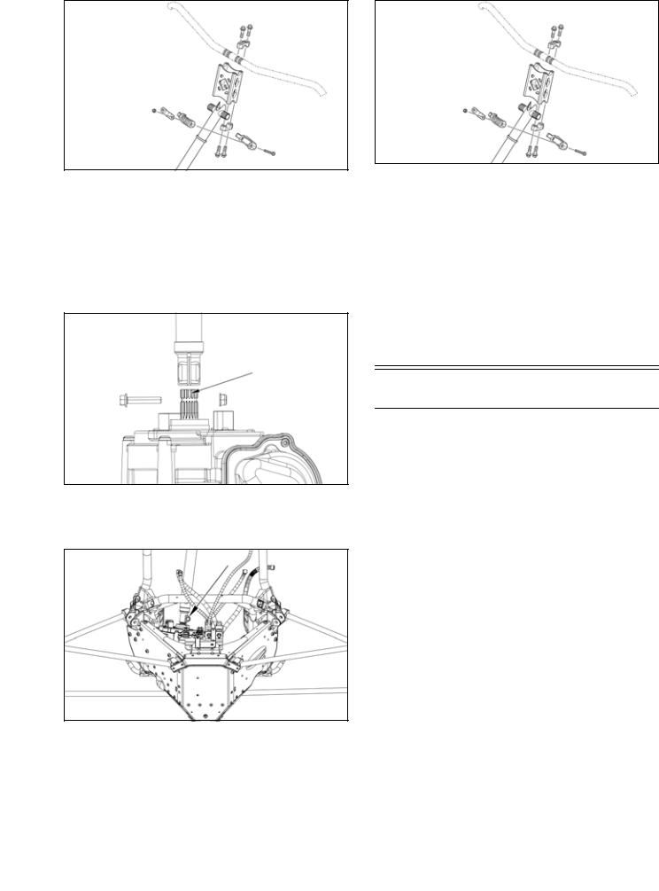
5.Remove the cap screws and handlebar caps securing the handlebar to the top of the handlebar riser; then remove the two Torx-head screws and nuts securing the top of steering post to the chassis. Account for both steering post blocks and retaining plate.
SNO-357
6.Carefully remove the steering post from the snowmobile.
INSTALLING
1.Install steering post into position and secure to the steering stop bracket with a new M10 nut. Be sure to align the steering post ball joint alignment tab with the steering stop bracket. Tighten to 55 ft-lb (74.8 N-m).
9
SNO-2218
2.Secure the tie rod assembly to the steering post using a new M10 nut. Be sure to align the tie rod ball joint alignment tab with the steering post. Tighten to 55 ft-lb (74.8 N-m).
SNO-2219
3.Secure the right-side steering boot to the chassis using the existing push rivets.
SNO-763
4.Secure the top of the steering post to the steering support using the existing retaining plate and nuts. Tighten to 96 in.-lb (10.8 N-m).
5.Install the expansion chamber using the existing springs; then connect the exhaust temperature sensor to the main harness.
6.Position the hood onto the snowmobile and connect the hood harness connector.
7.Secure the hood; then install the access panels.
Steering Post (EPS)
REMOVING
To remove the access panel and hood, use the following procedure:
1.Rotate the two quarter turns to the vertical position; then pull the top of the side panel out and up and off the skid plate.
2.Disconnect the hood harness on the left side of the hood; then loosen the two quarter turns securing the front of the hood. Pull the hood forward and remove the hood.
NOTE: On ATAC models, disconnect the suspension control module from the harness; then remove the module and bracket from the chassis.
0755-169
3.Remove the cap screw and nut securing the steering post to the EPS unit.
0755-170
4.Remove the cap screws and handlebar caps securing the handlebar to the top of the handlebar riser; then remove the two Torx-head screws and nuts securing the top of steering post to the chassis. Account for both steering post blocks and a retaining plate.
10
SNO-357
5.Carefully remove the steering post from the snowmobile.
INSTALLING
1.Align the gap of the steering post with the machined notch in the EPS unit spines; then install the steering post by moving it down until the cap screw hole in the post aligns with the horizontal groove in the EPS unit splines.
0755-173
2.Secure the steering post to the EPS unit using the existing cap screw and a new lock nut. Tighten to 12 N-m (108 in.-lb).
0755-170
3.Secure the top of the steering post to the steering support using the existing retaining plate, steering post blocks, and nuts. Make sure the throttle cable is positioned between the steering post blocks. Tighten to 11 N-m (96 in.-lb).
SNO-357
4.Install the handlebar riser onto the top of the steering post and secure using the existing cap screws and caps. Tighten evenly to 27 N-m (20 ft-lb).
NOTE: On ATAC models, connect the suspension control module to the harness; then attach the module and bracket to the chassis.
5.Position the hood onto the snowmobile and connect the hood harness connector and secure the two front quarter turns.
6.Install the access panel into the skid plate; then close the access panel and secure with the two quarter turns.
Ski
REMOVING
1.Elevate the front of the snowmobile and secure on a support stand.
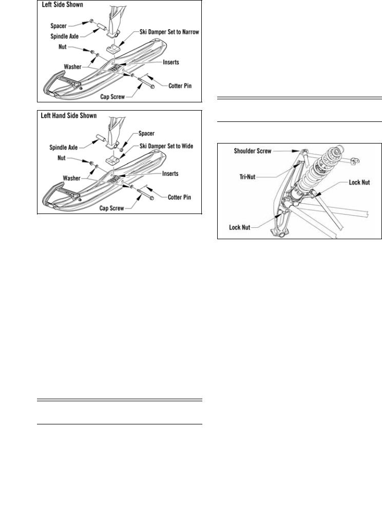
2.Remove and discard the cotter pin; then remove the nut and cap screw securing the ski to the spindle.
NOTE: Note the orientation of the damper for installation purposes.
3.Remove the ski. Account for the rubber damper and washers.
INSPECTING
1.Inspect the ski for cracks or deterioration.
2.Inspect the ski for abnormal bends or cracks.
3.Inspect the wear bar for wear.
4.Inspect all hardware and the spindle bushings for wear and damage.
5.Inspect the rubber damper for damage or wear.
INSTALLING
1.Slide a washer onto the cap screw used to secure the ski; then apply low-temperature grease to the shaft portion of the cap screw and spindle axle.
2.Install the spindle axle into the spindle; then position the ski damper into the bottom of the ski making sure the damper is properly positioned for the desired ski stance.
11
ONS-139
ONS-152
NOTE: The ski damper must be positioned in the ski so it is directly under the spindle.
3.With the cap screw hole of the ski centered with the spindle axle, slide the cap screw with washer through the outside of the ski and spindle assemblies.
NOTE: Local laws and/or regulations regarding maximum width of the ski stance may be applicable. Always comply with the maximum width laws and/or regulations when adjusting ski stance.
NOTE: Install the cap screw so the lock nut will be located to the inside of the ski and the cotter pin slot in the cap screw will be horizontal with the ski.
4.Install the remaining washer and lock nut; then tighten the lock nut to 35 ft-lb (47.6 N-m).
NOTE: Ensure that the cotter pin slot in the cap screw is still horizontal with the ski (see illustration); then proceed to step 5.
5.Install a new cotter pin from the back side of the ski cap screw and spread the pin.
Ski Wear Bar
The ski wear bar is a replaceable bar attached to the underside of the ski. If the snowmobile is operated primarily in deep snow, ski wear bar wear will be minimal; however, if the snowmobile is operated on terrain where the snow cover is minimal, the ski wear bar will wear faster. Arctic Cat recommends that the ski wear bars be replaced if worn to 1/2 of original diameter.
REMOVING
1.Raise the front of the snowmobile and secure with a suitable stand.
2.Remove the lock nuts securing the wear bar to the ski; then remove the wear bar.
INSTALLING
1.Install the wear bar into the ski making sure it is fully seated using a rubber mallet.
2.Secure the wear bar with lock nuts. Tighten to 15 ft-lb (20.4 N-m).
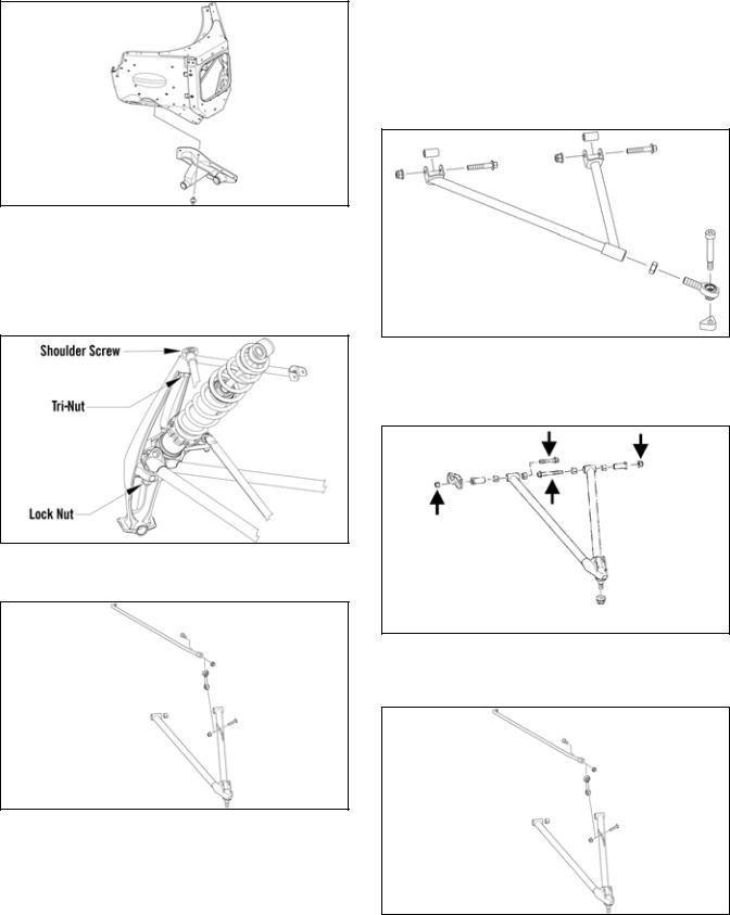
Spindle
REMOVING
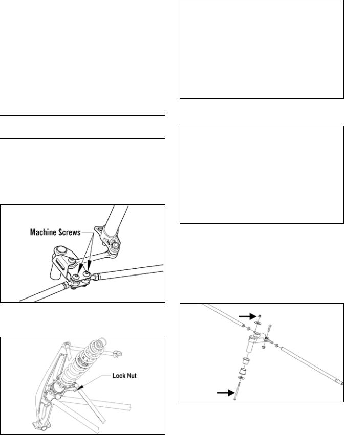
ONS-185
1.Position the front of the snowmobile on a safety stand; then remove the ski.
2.Remove the lock nut securing the tie rod to the spindle arm. Account for the washer on the top side.
3.Remove the shoulder screw and the tri-nut securing the upper A-arm to the spindle; then remove the lock nut securing the spindle to the lower A-arm. Using a rubber mallet, remove the spindle from the lower A-arm.
INSPECTING
1.Inspect the spindle for excessive wear, cracks, bends, or imperfections.
2.Inspect the A-arm bushings and axle area for wear.
3.Inspect the ski spindle axle and bearings for wear, damage, or loose fit. Replace the bearings as a set.
NOTE: Replacing the spindle bushings is difficult.
The existing bushings will be damaged during removal. Be careful, however, not to damage the spindle when removing the bushings. Press the new bushings into the spindle.
INSTALLING
1.Position the lower A-arm into the spindle; then loosely secure with a new lock nut.
2.Position the upper A-arm end with the top of the spindle; then secure the A-arm end to the spindle using the existing shoulder screw and tri-nut. Tighten to 20 ft-lb (27.2 N-m).
12
3.Remove the snowmobile from the support stand. Tighten the lower A-arm lock nut to 45 ft-lb (61.2 N-m).
NOTE: The weight of the snowmobile will allow the ball joint to seat into the spindle before tightening the nut.
4.Place the tie rod with washer into position on the spindle arm. Secure with a new lock nut. Tighten to 32 ft-lb (43.5 N-m).
5.Install the ski using the existing hardware and new cotter pin. Tighten the cap screws to 35 ft-lb (47.6 N-m).
6.Turn the handlebar fully to the right and then to the left to verify the steering moves freely.
Steering Tie Rod
NOTE: To access the steering arm, the steering tie rods must be removed.
REMOVING
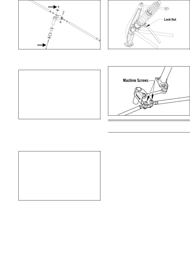
1.Remove both machine screws and nyloc nuts securing the steering tie rod ends to the steering arm. Discard both nuts.
SNO-349
2.Remove the lock nuts securing the steering tie rod ends to the spindle arms. Account for the washers and discard both nuts.
ONS-189
3.Slide the steering tie rod out of the steering boot and out of the snowmobile.
4.Remove the screw and lock nut securing the steering tie rod end to the steering arm. Discard the nut.
SNO-350
5.Remove the lock nut securing the steering tie rod to the steering post. Discard the nut.
PC099C
NOTE: At this point if the technician’s objective is to remove the steering arm, the reinforcement bracket will need to be removed by drilling out the appropriate rivets.
6.Remove all Torx-head screws securing the front skid plate to the chassis; then remove the cap screw and nut securing the steering arm to the chassis. Account for two washers and two bushings.
SNO-829A
INSPECTING
1.Inspect the ball joints for damaged threads or wear.
2.Inspect the tie rod for damage, unusual bends, or wear.
INSTALLING
1.Secure steering arm into position and secure using the existing cap screw and flat washers, and new nut. Tighten to 8 ft-lb (10.9 N-m).
13
SNO-829A
2.Place the steering tie rod into position on the steering post. Secure with a new nyloc nut. Tighten to 55 ft-lb (74.8 N-m).
SNO-351
NOTE: Make sure the tie rod tab is fully seated into the steering post and threads of the ball joint are above the nut when tightened correctly.
3.Place the tie rod end into position on the steering tie rod bracket. Secure with a new nyloc nut. Tighten to 20 ft-lb (27,2 N-m).
SNO-350
4.Slide the steering tie rod through the steering boot and into the snowmobile; then place the steering tie rod into the spindle arm with the washer. Secure with a new lock nut. Tighten to 32 ft-lb (44 N-m).
ONS-189
5.Secure the steering tie rod to the steering tie rod bracket with the screw and new nyloc nut. Tighten to 20 ft-lb (27.2 N-m).
SNO-349
Ski Alignment
CHECKING
NOTE: Track tension and alignment must be properly adjusted prior to checking or adjusting ski alignment. Ski alignment must be performed on a flat, level surface. Ski toe-out must fall within the range of 1/16-1/4 in (1.6-6.4 mm).
1.Raise the front end of snowmobile just high enough to keep the skis from contacting the floor.
2.Turn the handlebar to the straight-ahead position. Visually inspect the handlebar for being centered and in the straight-ahead position.
3.With the handlebar in the straight-ahead position, secure the handlebar to prevent the alignment from becoming disturbed during the remainder of the alignment procedure.
NOTE: Track tension and alignment must be properly adjusted prior to placing the straightedge against the outside edge of the track.
4.Place a long straightedge against the outside edge of the track so it lies near the inside edge of the left-side ski.
NOTE: The straightedge should be long enough to extend from the back of the track to the front of the ski.
14
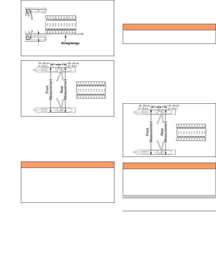
5.Measure the distance from the straightedge to the left-side ski wear bar bolts in two places: approximately 7-8 in. (18-20 cm) in front of the spindle and 7-8 in. (18-20 cm) behind the spindle. Record the measurements taken for the left side.
729-887A
0734-408
6.Place the straightedge against the outside edge of the track so it lies near the inside edge of the right-side ski.
7.Measure the distance from the straightedge to the right-side ski wear bar bolts in two places: 7-8 in. (18-20 cm) in front of the spindle and 7-8 in. (18-20 cm) behind the spindle. Record the measurements taken for the right side.
! WARNING
The measurement from the front and rear wear bar bolts to the straightedge can be equal (ski parallel to the track), but the front measurement must never be less (ski toed-in) or poor handling will be experienced. The front wear bar bolt measurement to the straightedge must not exceed the measurement from the rear wear bar bolt to the straightedge (ski toed-out) by more than 5/32 in. (4 mm).
8.If ski alignment is not as specified, adjust the alignment of the ski(s) not parallel to the straightedge.
ADJUSTING
NOTE: The following procedure can be used to adjust the alignment of either ski.
NOTE: The rivets securing the steering boots will have to be removed in order to adjust the inner tie rod ends.
1. Secure the steering tie rod in the centered position.
2.Loosen both spindle tie rod jam nuts on the same side as the ski to be aligned.
3.Using a wrench on the spindle tie rod “flats,” rotate the spindle tie rod until recommended specification is attained.
4.Apply blue Loctite #243 to each jam nut thread area; then tighten the jam nuts against the spindle tie rod.
NOTE: Repeat this procedure on each side (if necessary) until ski toe-out is within specification.
! WARNING
Neglecting to lock the tie rod by tightening the jam nuts may cause loss of snowmobile control and possible personal injury.
VERIFYING
1.With the handlebar in the straight-ahead position, verify ski alignment by measuring across from the outside edge of the left-side wear bar bolts to the outside edge of the right-side wear bar bolts (without using the straightedge) in two places: approximately 7-8 in. in front of the spindle and 7-8 in. behind the spindle.
2.The measurement from in front of the spindle to the outer edge of the wear bar bolts (without using the straightedge) must not exceed the rear measurement by more than 1/16-1/4 in. toe-out (1.6-6.4 mm).
0734-408
! WARNING
The measurement taken in front of the spindle must never be less than the measurement taken behind the spindle or poor handling will be experienced. Neglecting to lock the tie rod by tightening the jam nuts may cause loss of snowmobile control and possible personal injury.
A-Arms
REMOVING
1.Elevate the front of the snowmobile and secure using a suitable support stand.
2.Remove the Torx-head screws securing the front skid plate to the chassis; then remove the front skid plate.
15
3.Remove the eight push rivets securing the steering boot to the chassis; then slide the boot away from the chassis.
SNO-763
4.Remove the ski shock.
5.Remove the shoulder screw and tri-nut securing the upper A-arm and the lower lock nut securing the lower A-arm. Using a rubber mallet, remove the lower arm from the spindle. Discard the lower lock nut.
ONS-190
6.Remove the cap screw and lock nut securing the sway bar link to the lower arm.
SNO-764
7.Remove the two cap screws and nyloc nuts securing the lower A-arm to the chassis; then slide the boot from the arm and remove the arm.
8.Remove the two cap screws and lock nuts securing the upper arm to the chassis.
INSPECTING
1.Inspect the arm welded areas for cracks or any signs of deterioration.
2.Inspect the bearings and axles for wear or damage.
3.Inspect the arm tubing for signs of twisting or bending.
4.Inspect mounting location of the chassis for cracks or wear.
INSTALLING
1.Place the upper arm into position on the chassis and secure with the cap screws and new nyloc nuts. Tighten to 20 ft-lb (27.2 N-m).
SNO-572
2.Slide the lower arm into the boot; then place the arm into position on the chassis. Secure with the cap screws and new nyloc nuts and tighten to 65 ft-lb (88.4 N-m) (front) and 45 ft-lb (61.2 N-m) (rear).
SNO226A
3.Secure the sway bar link to the lower arm with the cap screw and new nyloc nut. Tighten to 23 ft-lb (31.3 N-m).
SNO-764
4.Position the lower A-arm into the spindle; then loosely secure with a new lock nut.
16
5.Position the upper A-arm end with the top of the spindle; then secure the A-arm end to the spindle using the existing shoulder screw and tri-nut. Tighten to 20 ft-lb (27.2 N-m).
6.Tighten the lower A-arm lock nut to 45 ft-lb (61.2 N-m).
7.Install the ski shock absorber. Tighten to 32 ft-lb (43.5 N-m).
8.Place the front skid plate into position; then secure with the Torx-head screws.
NOTE: On models with FOX iQS shocks, once the shocks are installed, route the wires around the shock and connect to the shock making sure they click into place. Cable tie the wires to the shock body.
YM-218
Ski Shock Absorber
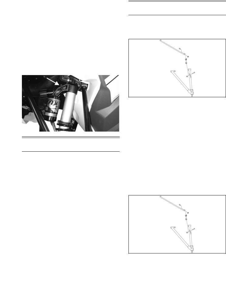
REMOVING
1.Position the front of the snowmobile on a safety stand taking all pressure off the skis.
2.Remove the cap screws securing the shock absorber to the chassis and the lower A-arm; then remove the shock absorber. Account for all mounting hardware.
CLEANING AND INSPECTING
1.Inspect the shock absorber seal area for signs of excessive oil leakage.
2.Inspect the shock absorber mounting eyelet, bushings, and sleeve for wear or damage.
3.Inspect the threaded shock sleeve for damage or wear.
INSTALLING
1.Using the Shock Spring Removal Tool, place the spring on the shock absorber and secure with the retainer.
2.Adjust the retainer nut (spring adjuster) (if applicable) until the specified amount of threads are exposed between the spring adjuster and the shock housing (noted in removing) as an initial setting.
3.Install the bushings, sleeves, and spacers into each shock end; then place the shock absorber into position and secure with the cap screws and new lock nuts. Tighten the lock nuts to 32 ft-lb (43.5 N-m).
Sway Bar
REMOVING
1.Remove the nyloc nuts and cap screws securing the sway bar link to the lower A-arm and the sway bar.
SNO-764
2.Remove the Torx-head screws securing the sway bar mounting brackets; then pull the sway bar out of the snowmobile.
INSPECTING
1.Inspect the sway bar for any signs of twisting, fatigue, or wear.
2.Inspect the sway bar arms for cracks or damage.
3.Inspect the links, bushings, bushing retainers, and hardware for damage or wear.
INSTALLING
1.Place the sway bar into the sway bar mounting brackets; then install the sway bar into the snowmobile. Secure with the Torx-head screws and tighten to 96 in.-lb (10.8 N-m).
2.Secure the sway bar links to the sway bar and lower A-arm with the cap screws and new nyloc nuts. Tighten to 23 ft-lb (31.3 N-m).
SNO-764
17
Front Bumper
REMOVING/INSTALLING
1.Remove all Torx-head screws securing the front bumper; then remove the bumper.
2.With the bumper in position, install all Torx-head screws. Tighten securely.
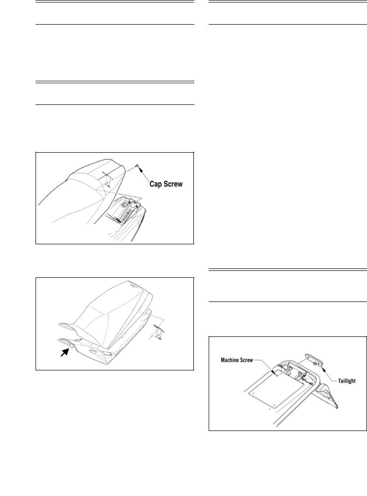
Seat Assembly
NOTE: On models with heated seats, be sure to disconnect the seat heater harness before removing the seat.
1.Remove the cap screw securing the rear of the seat; then remove the seat.
SNO-261A
2.Route the front tab on the seat through the seat-base hold-down bracket; then install the seat and secure using the cap screw.
SNO-227A
NOTE: On models with heated seats prior to lowering and securing the seat, connect the seat heater harness connector.
Seat Cushion
REMOVING
1.Remove the seat assembly.
2.Using a sharp tool, pry out all staples securing the seat cover to the plastic seat base.
3.From beneath the seat foam, remove the seat wire from the two elastic loops; then remove the cover from the seat base and seat foam.
INSTALLING
1.Position the cover over the seat foam and seat base; then pull the two elastic loops through the slots in the seat foam and secure with the seat wire. Check to make sure it is positioned straight.
2.Fold the rear edge of the cushion down and around the plastic base. Using a staple gun and 1/4 in. staples, staple the rear flap of the cushion to the plastic base in the same areas as the original staples were located. Position staples 1 in. (2.54 cm) apart.
3.Fold the sides of the cushion down around the bottom edge of the plastic seat base. Position the staples in the same area as the original staples were located.
NOTE: Note the cushion fit. If any wrinkles are noted, remove by pulling the cushion material in the appropriate direction before securing with staples.
4.Fold the front cushion material back and onto the plastic seat base. Check for wrinkles and secure with staples and two screws.
5.Install the seat assembly.
Taillight/Brake Light
Assembly
1.Remove the two machine screws securing the taillight to the taillight support; then disconnect the taillight harness connector.
SNO-511
2.Connect the taillight harness connector; then secure the taillight to the taillight support with the two machine screws. Tighten to 48 in.-lb (5.4 N-m).
18
Rear Bumper/Snowflap
REMOVING BUMPER
1.Remove and retain only the two machine screws securing the rear of the skid frame assembly.
2.Place cardboard or a suitable substitute on the floor to protect the snowmobile from being scratched; then install Steering Post Stand for the standard steering models or Handlebar Stand for the adjustable steering models into the lower holes in the handlebar riser (from the left-side) and tip the snowmobile onto its left side.
3.Swing the skid frame assembly away from the chassis; then using a 3/16-in. drill bit, remove all rivets securing the left-side of the bumper; then repeat for opposite side.
4.Remove and retain the two machine screws and nuts securing the front of the existing bumper to the chassis.
5.Remove the two rivets securing the snowflap to the bumper. Remove the bumper.
INSTALLING BUMPER
1.Align the holes in the bumper with the existing holes in the tunnel; then using new rivets, secure rear bumper to the tunnel; then secure the snowflap to the rear bumper using new rivets.
2.Secure the front of the bumper to the chassis using the existing machine screws and nuts. Tighten securely.
3.Install skid frame assembly using two existing machine screws. Tighten securely.
REMOVING SNOWFLAP
1.Drill out the rivets securing the snowflap to the tunnel; then remove the snowflap.
INSTALLING SNOWFLAP
1.Secure the snowflap to the tunnel using the appropriate rivets.
Windshield/Console/
Headlight
REMOVING
1.Remove and retain all machine screws securing the hood; then disconnect the console harness and remove the hood assembly.
2.Remove the eight screws securing the windshield to the console; then remove the windshield.
3.Remove the four screws securing the console.
0753-033
4.Disconnect the gauge, electrical accessory wires, and the ignition switch.
5.Remove the two screws securing the rear of the console to the hood (on the underside of the hood).
6.Loosen the two side headlight assembly screws; then remove the two front headlight assembly screws.
0753-034
7. Remove the headlight assembly.
INSTALLING
1.With the headlight assembly in position, install the front headlight assembly screws. Engage the side headlight screws in the slots and tighten until snug.
2.Engage the side console tabs on the headlight assembly; then place the front of the console over the headlight assembly and press down until it snaps in place.
3.Install the two screws securing the rear of the console to the hood. Tighten only until snug.
4.Place the windshield brace assembly into position and secure to the console with the four screws. Tighten until snug.
5.Connect the gauge; then connect the electrical accessory wires and the ignition switch.
6.With the windshield in position, secure the windshield to the frame using the four screws. Tighten securely.
7.Connect the console harness; then install the hood assembly and secure with the screws.
19
Adjusting Headlight Aim
The headlight can be adjusted for vertical aim of the HIGH/LOW beam. The geometric center of LOW beam zone is to be used for vertical aiming.
1.Position the snowmobile on a level floor so the headlight is approximately 25 ft (7.62 m) from an aiming surface (wall or similar surface).
NOTE: There should be an “average” operating load on the snowmobile when adjusting headlight aim.
2.Measure the distance from the floor to midpoint of the headlight.
3.Using the measurement obtained in step 2, make a horizontal mark on the aiming surface.
4.Make a vertical mark intersecting the horizontal mark on the aiming surface directly in front of the headlight.
5.Engage the brake lever lock and start the engine. Select the headlight dimmer switch LOW beam position. DO NOT USE HIGH BEAM.
6.Observe the headlight beam aim. Proper aim is when the most intense beam is centered on the vertical mark 5 cm (2 in.) below the horizontal mark on the aiming surface.
7.Adjust the headlight using the adjusting screw on the backside of the headlight housing until correct aim is obtained. Shut the engine off; then disengage the brake lever lock.
0750-309
20
Engine
NOTE: Whenever a part is worn excessively, cracked, or damaged in any way, replacement is necessary.
SPECIAL TOOLS
A number of special tools must be available to the technician when performing service procedures in this engine section.
NOTE: When indicated for use, each special tool will be identified by its specific name, as shown in the chart below, and capitalized.
Description |
p/n |
Drive Clutch Bolt Tool |
0644-281 |
Drive Clutch Puller |
0744-062 |
Drive Clutch Spanner Wrench |
0644-136 |
Engine Lift Plate |
0744-073 |
Hood Harness Extension |
1686-659 |
NOTE: Special tools are available from the Arctic
Cat Service Parts Department.
CAUTION
Never attempt to substitute any other drive clutch puller for the recommended puller or severe clutch or crankshaft damage will occur.
Engine Removing/Installing
This engine sub-section has been organized to show a progression for the removing/installing the Arctic Cat 9000 engine. For consistency purposes, this sub-section shows a complete and thorough progression; however, for efficiency it may be preferable to remove only those components needing to be addressed. Also, some components may vary from model to model. The technician should use discretion and sound judgment.
Removing
NOTE: While removing the engine, note all cable tie locations.
1.Remove both access panels; then loosen the two quarter-turns securing the hood. Disconnect the hood harness and pull the hood forward and off of the snowmobile.
2.Remove the seat; then remove the gas cap and retaining nut from the neck of the gas tank. Remove the eight screws securing the console. Remove the console.
YM-176A
3.Remove the gas tank assembly.
4.Remove the cap screw from the secondary sheave and slide the secondary sheave (along with the drive belt) off the driven shaft. Account for alignment washers and sheave adjuster.
5.Remove the cap screw and washer securing the primary sheave to the crankshaft.
6.Using Primary Sheave Puller, tighten the puller. Remove the primary sheave.
NOTE: If the primary sheave will not release, sharply strike the head of the puller. Repeat this step until the sheave releases.
7.Remove the Torx-head screws and both access plates from beneath the snowmobile.
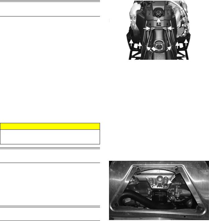
8.Place a drain pan beneath the engine oil drain screw; then remove the screw and allow the oil to drain completely. After the oil has drained, install the drain plug and tighten to 7.2 ft-lb (9.8 N-m).
YM-152A
9.Remove the four Torx-head screws securing the right-side footrest to the tunnel and the support; then with a drain pan in position, remove the drain plug from the oil tank.
21
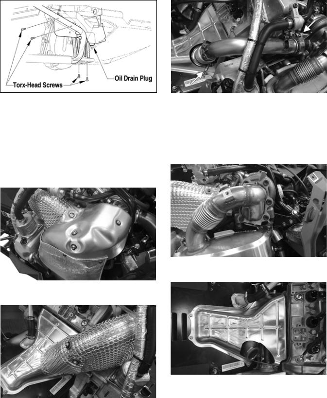
746-121A
NOTE: To aid in draining the oil from the reservoir, position a funnel between the tank and the opening of the tunnel running board.
10.After the oil has drained completely, install the drain plug with a new O-ring and tighten to 16 ft-lb (21.8 N-m).
11.Using a suitable vacuum pump, remove the coolant from the coolant filler neck and the reservoir tank.
12.Remove the five screws and washers securing the turbo heat shield to the turbo. Remove the shield.
YM-181
13.Remove the cap screws and washers securing the heat shield to the manifold.
YM-155
14.Apply a small amount of penetrating lubricant to the threads of the two clamp threads; then remove the two nuts securing the exhaust pipe clamps. Remove the clamps and the pipe.
YM-182A
15.Remove the six Torx screws securing the resonator to the turbo; then remove the spring securing the resonator. Remove the resonator and account for a gasket.
NOTE: Apply a small amount of penetrating oil to the Torx screws before removing the screws. Disassemble with hand tools and T50 ball head Torx bit (p/n 0644-623).
YM-154
16.Remove the screws and washers securing the exhaust heat shield to the tunnel.
YM-157
17.Remove the hose clamps securing hoses to the turbo, intake manifold, intercooler, and the air bypass valve. Remove both hoses.
22
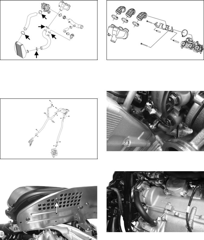
SNO-835A
18.Remove the steering post assembly; then remove the two cap screws and nuts securing the vapor tank to the right-side support.
19.Remove the cap screws securing the front spars to the chassis; then remove the cap screws and nuts securing the right-side support to the chassis. Remove the steering support as an assembly.
SNO-836
20.Remove the screws securing the air silencer to the clutch guard; then disconnect the hose from the top of the engine and the waste gate hose. Remove the air silencer assembly.
YM-185A
21.Remove the two cap screws and spacers securing the intake manifold and throttle body to the engine; then remove the three clamps securing the intake boots to the throttle body. Remove the intake manifold.
SNO-837
22.Remove the clamp securing the intake duct to the PTO-side of the turbo.
23.Remove the hose clamp securing the coolant hose to the vapor tank; then remove the hose clamp securing the coolant hose from the bottom of the turbo.
YM-164
24.Remove the clamp securing the oil return hose to the crankcase; then remove the oil delivery hose to the cylinder. Account for two washers.
YM-165A
23
YM-163
25.Remove the four cap screws and four nuts securing the right-side chassis support to the chassis. Remove the turbo and support assembly.
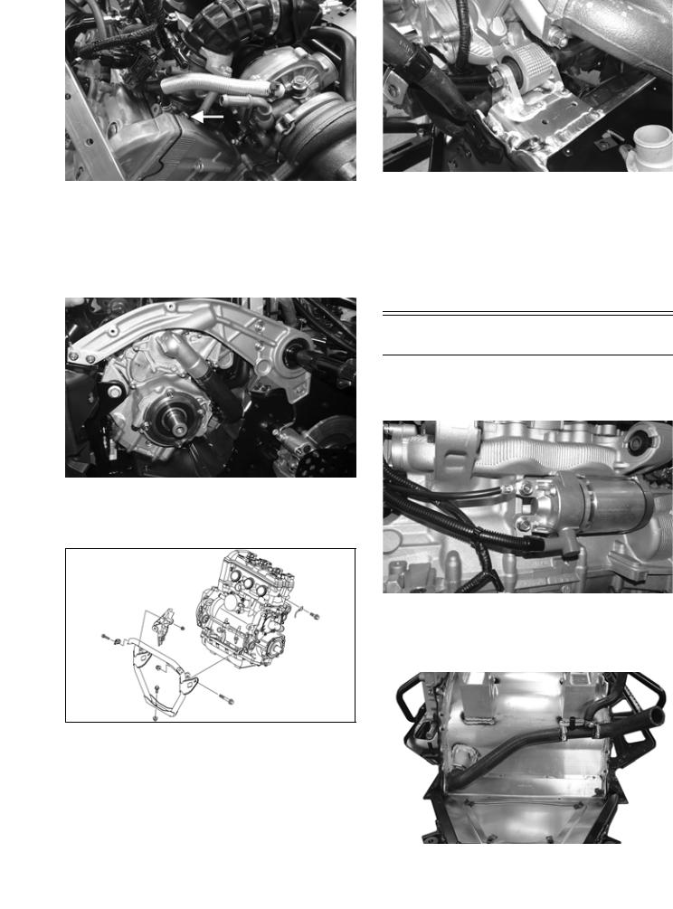
26.Remove the three screws and one nut securing the clutch guard; then remove the screws and nuts securing the left-side chassis support. Rotate the support up to gain access to the rear engine cap screw.
YM-160
29.Remove the clamp securing the MAG-side coolant hose to the engine; then disconnect the oil pressure switch and the oil pressure sensor.
30.With all hoses and wires disconnected from the engine, move the engine forward and out the right-side of the chassis.
31.Remove the throttle body assembly once the engine is removed.
YM-186
27.Remove all six cap screws and nuts securing the front engine bracket; then remove the bracket. Remove the cap screw securing the ground wire to the engine.
ONS-030
28.Remove the cap screw and nut securing the rear of the engine to the chassis.
Installing
NOTE: Before installing the engine, be sure the starter motor and cables are installed and secured to the engine.
YM-162
NOTE: If the thermostat-to-heat exchanger coolant hose was removed, make sure it is properly routed and installed onto the heat exchanger. Tighten to 35 in.-lb (4 N-m).
YM-159
24
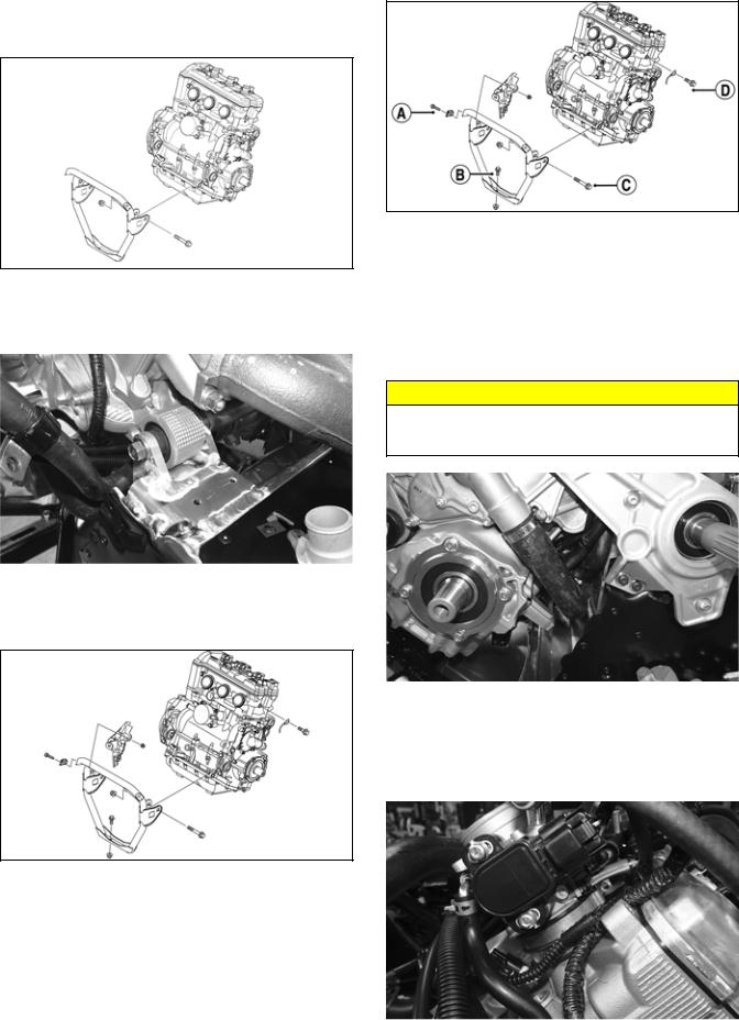
1.Position the front engine bracket with the front engine mounts; then loosely secure using the existing cap screws and new nuts.
SNO-365
2.Carefully lower the engine into the chassis aligning the rear engine mounts with the chassis mounts; then loosely secure using the existing cap screw and a new nut.
ONS-030A
6.Connect the oil pressure switch and the oil pressure sensor to the main harness.
7.Connect the coolant hose from the heat exchanger to the water pump and secure using the existing hose clamp. Tighten to 35 in.-lb (4 N-m).
NOTE: All wires, cables, and hoses must be installed on the inside of the coolant hose and the PTO-side bracket.
CAUTION
Make sure the top clamp is routed like the image below so the clamp does not come in contact with the primary sheave.
YM-160
3.Loosely secure the front engine mounting bracket to the chassis using the existing cap screws and new nuts; then loosely secure the ground cable to the engine using the existing cap screw and a new nut.
ONS-030
4.Tighten the rear engine cap screw and nut to 65 ft-lb (88.4 N-m).
5.Tighten the cap screws (A and B) to 25 ft-lb (34 N-m). Tighten cap screw (C) to 65 ft-lb (88.4 N-m). Tighten cap screw (D) to 96 in.-lb (10.8 N-m).
YM-161
NOTE: Route the positive and negative battery cables up and over the engine mounts.
8.Install the throttle body assembly into the three intake boots and secure using the existing clamps. Tighten to 26 in.-lb (2.9 N-m).
YM-168
25
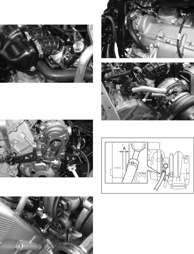
9.Install the throttle body coolant hoses to the engine and the water pump. Secure using the existing clamps.
10.Install the intake manifold assembly onto the throttle body assembly and secure using the existing clamps. Tighten to 20 in.-lb (2.3 N-m).
11.Secure the manifold bracket to the engine using the existing cap screws and spacers. Tighten to 7.2 ft-lb (9.8 N-m).
YM-169
12.Position the right-side rear spar with the chain case assembly; then install the existing cap screws through the chain case and the spar.
13.With the turbo installed onto the MAG-side mounting bracket; secure the assembly to the chassis using the existing screws and nuts. Tighten to 20 ft-lb (27.2 N-m).
YM-163
14.Connect the lower coolant hose on the backside of the turbo to the oil cooler. Secure using the existing hose clamp. Tighten to 35 in.-lb (4 N-m).
YM-164
15.Secure the oil return hose to the crankcase using the existing clamp; then secure the oil delivery hose to the cylinder using the existing banjo bolt and new washers. Tighten to 7.2 ft-lb (9.8 N-m).
YM-165A
YM-163
NOTE: Make sure the distance (A) between the oil delivery hose and the turbo is 3.0 mm (0.12 in.).
SNO-821
16.Install the front two spars to the chassis and loosely secure using the existing cap screws and nuts; then position the steering support over all four spars and loosely secure using the existing cap screws and nuts. Tighten all cap screws to 25 ft-lb (34 N-m).
26
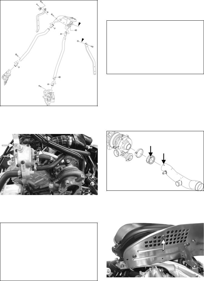
SNO-828
17.Secure the vapor tank assembly to the right-side rear spar using the existing cap screws and nuts; then connect the coolant hose to the turbo fitting and oil tank breather line to the air intake tube. Tighten the hose clamps to 35 in.-lb (4 N-m).
YM-167A
18.Install steering post through the intake manifold and into position. Secure to the steering stop bracket with a new M10 nut. Be sure to align the steering post ball joint alignment tab with the steering stop bracket. Tighten to 55 ft-lb (74.8 N-m).
SNO-2218
19.Secure the tie rod assembly to the steering post using a new M10 nut. Be sure to align the tie rod ball joint alignment tab with the steering post. Tighten to 55 ft-lb (74.8 N-m).
SNO-2219
20.Secure the right-side steering boot to the chassis using the existing push rivets.
21.Secure the top of the steering post to the steering support using the existing retaining plate and nuts making sure the throttle cable is routed between the steering bushings. Tighten to 96 in.-lb (10.8 N-m).
22.Install the intake duct to the turbo and secure using the existing clamp and boot making sure to align the alignment marks. Tighten the hose clamp to 35 in.-lb (4 N-m).
SNO-879A
23.Install the air silencer onto the air duct; then install the hoses from the air bypass valve and the hose from the top of the engine into the air silencer. Secure the silencer using the existing screws. Tighten securely.
YM-185A
27
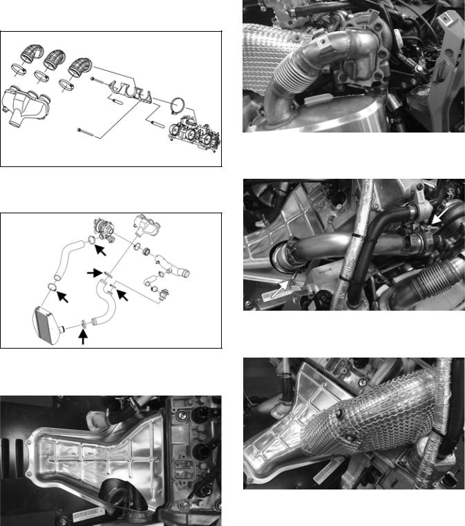
24.Install the intake manifold assembly onto the throttle body and secure using the existing clamps. Tighten to 1.7 ft-lb (2.3 N-m).
25.Using the long (PTO-side) and the short (MAG-side) spacers, secure the intake manifold assembly to the engine using the existing cap screws. Tighten to 7.2 ft-lb (9.8 N-m).
SNO-837
26.Install the hoses to the intercooler, turbo, intake manifold, and air bypass valve using the existing clamps. Tighten to 35 in.-lb (4 N-m).
SNO-835A
27.Install the exhaust heat shield onto the tunnel and secure using the screws and washers. Tighten securely.
YM-157
28.Position the exhaust gasket between the turbo and the resonator; then using the long T50 ball head Torx bit, secure the resonator to the turbo using the existing screws. Tighten the screws to 9 ft-lb (12.2 N-m) then to 18 ft-lb (24.5 N-m) in a crisscross pattern.
NOTE: Apply a small amount of C5-A copper based anti-seize lubricant to the threads of the screws. Hand tools should be used when installing the six Torx screws.
YM-154
29.Install the exhaust pipe onto the exhaust manifold and the turbo and secure using the existing clamps. Tighten to 6.1 ft-lb (8.3 N-m).
YM-182A
30.Install the exhaust heat shield to the exhaust pipe using the existing cap screws and washers. Tighten securely.
YM-155
31.Install the turbo heat shield and secure using the existing cap screws and washers. Tighten securely.
28
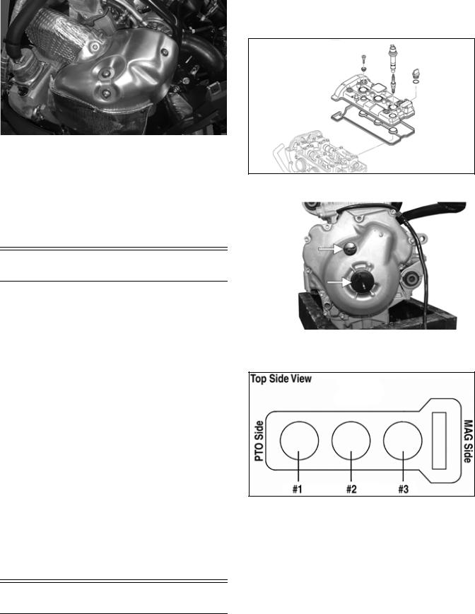
YM-251
32.Install the gas tank assembly and connect the battery; then install the console making sure to connect the reverse alarm and heated seat switch.
33.Install the drive clutch, drive belt, and driven clutch.
34.Install the seat and secure using the screw. On models with a seat heater, connect the seat heater harness connector.
35.Install the hood and both access panels.
Engine Servicing
This engine sub-section has been organized to show a progression for servicing the Arctic Cat 9000 engine. For consistency purposes, this sub-section shows a complete and thorough progression; however, for efficiency it may be preferable to disassemble only those components needing to be addressed. Also, some components may vary from model to model. The technician should use discretion and sound judgment.
SPECIAL TOOLS
A number of special tools must be available to the technician when performing service procedures in this engine section.
NOTE: When indicated for use, each special tool will be identified by its specific name, as shown in the chart below, and capitalized.
Description |
p/n |
Ball Hone |
0644-532 |
Flywheel Puller Kit |
0744-083 |
Piston Pin Puller |
0644-328 |
V Blocks |
0644-535 |
Drive Clutch Spanner Wrench |
0644-136 |
Ring Compressor |
0644-378 |
NOTE: Special tools are available from the Arctic
Cat Service Parts Department.
Disassembling
1.With the engine secured to a suitable engine stand, remove the ignition coils from the cylinder head cover; then remove the spark plugs.
2.Remove the four Allen-head screws securing the cylinder head cover to the cylinder head; then remove the cover. Account for the gasket.
SNO-621
3. Remove both plastic plugs from the MAG cover.
YM-003A
NOTE: The engine cylinders are numbered #1, #2, and #3 from the PTO to the MAG.
SNO-318A
4.Obtain top-dead-center (TDC) by rotating the crankshaft (clockwise) until the mark on the magneto rotor is aligned with the pointer on the magneto cover and the #3 piston is at TDC.
29
Loading...