

Arc Machines 415 WDR User Manual

Docume
Revision N
nt No. 740084
MODEL 415
OPERATION MANUAL

Model 415
Operation Manual
NOTICE
This document and the information contained herein is the property of Arc Machines, Inc. It is proprietary
and submitted and received in confidence. It shall be used only for the purpose for which it is submitted and
shall not be copied in whole or in part without the prior express written permission of Arc Machines, Inc.
The information in this document has been carefully reviewed and is believed to be accurate. However, no
responsibility is assumed for inaccuracies.
Information and instructions in this document are subject to change and Arc Machines, Inc. reserves the right
to change specifications and data without notice.
WARNING
The nature of the GTAW process creates some POTENTIAL HAZARDS. In accordance with international
safety regulations the EXCLAMATION SYMBOL indicates that this equipment is considered HAZARDOUS
until an operator has been made aware of these POTENTIAL HAZARDS by READING THIS MANUAL. The
LIGHTNING FLASH SYMBOL indicates that there are potential electrical hazards. The use and display of
these symbols make it the OPERATOR’S RESPONSIBILITY TO INSURE THAT HE HAS READ AND/OR
BEEN MADE AWARE OF ALL OF THE SAFETY-RELATED ITEMS CONTAINED IN THIS MANUAL.
Publication date : First Edition - 1 July 1997
Copyright 1997 by Arc Machines, Inc.
All rights reserved
REV DCO # CHANGE DESCRIPTION DATE APR
A 3228 Revised pg. iv,2.1,2.2,3.2,3.5,Sect. 5 Add 3.11 1/27/99 GPE
B 3304 Revised pages iv, 2.1, 2.2, 3.5, 5.10 thru 5.20 4/20/99 GPE
C 3518 Revised Sec 5.6, corrected sec # error, added sec
5.18, 5.19, 5.20 updated Index page numbers
D 3548 Revised pages i, 2.1, 2.2 2/08/00 GPE
E 3632 Revised pages 3.2 and 3.3 5/18/00 GPE
F 3749 Revised page 2.5 Removed algaecide requirement 10/17/00 GPE
G 3779 Revised pages 5.1 to 5.11, Cal clarification 11/28/00 GPE
H 3829 Revised pages 5.1 to 5.8. change volt tolerance 03/15/01 LEC II
J 5229 Replace floppy drive with USB, update Section 3.3,
Remove Section 5.18, 5.19, 5.20
K 5097 Correct Terminal Jumper Settings on page 3.5 12/18/08 BF
L 5450 Correct typo’s per BPMI-RS-P-02745, Update Input
Power Detail Section 2.0
M 6245 Removed description of Neutral Overload (4.4.6) 2/7/12 SM
N 6412 Add CMOS battery replacement procedure section
5.18, reformat pagination
Docume
Revision N
nt No. 740084
i
12/07/99 GPE
12/10/08 BF
9/29/09 BF
11/05/12 DC

Model 415
Operation Manual
EFFECTIVITY
Features and operation of the Model 415 are derived mostly from SOFTWARE. This document is
based on the latest STANDARD version of SOFTWARE at the time of last revision (see revision
page).
Some deviations in actual operation, from this document, are possible depending on the software
version of a particular machine. Please feel free to contact Arc Machines Service Department for
documentation or information on how software updates affect this document.
Docume
Revision N
nt No. 740084
ii

Model 415
Operation Manual
TABLE OF CONTENTS
SECTION DESCRIPTION PAGE
SECTION I INTRODUCTION
1.0 Introduction 1
1.1 Safety Precautions 1
1.2 Operational Precautions 3
1.3 RF and EMI emissions 4
1.4 Shock Hazard Warning 5
SECTION II SPECIFICATIONS
2.0 Electrical 6
2.1 Physical Construction 7
2.2 Current Output 8
2.3 Arc Voltage and Arc Voltage Control Servo 8
2.4 Travel Servo 8
2.5 Wire Feed Servo 8
2.6 Torch Oscillation and Cross-seam Steering Servo 9
2.7 Timing Functions 9
2.8 Arc Starting 9
2.9 Torch Cooling Unit 10
SECTION III INSTALLATION
3.0 Installation, General 11
3.1 Training 11
3.2 Inspection 11
3.3 Torch Cooling System Preparation 12
3.4 Primary Power Connection 13
3.5 Operators Pendant Connection 16
3.6 Inert Gas Connection 16
3.7 Weld Head Installation 16
3.8 Initial Turn On 17
SECTION IV SYSTEM FUNCTIONS
4.0 Introduction 21
4.1 Multi-Level Functions and Modes 21
4.2 Single Level Functions and Modes 22
4.3 Miscellaneous Non-Programmable Functions 22
4.4 Sensors and Faults 23
4.5 Pendant Controls 23
4.6 Other System Features 24
4.7 Weld Sequence 25
Docume
nt No. 740084
Revision N
iii

Model 415
Operation Manual
TABLE OF CONTENTS
SECTION DESCRIPTION PAGE
SECTION V OPERATION
5.0 Introduction 30
5.1 Initial Power-On 30
5.2 Power Supply Calibration Introduction 30
5.3 Required Equipment For Calibration 31
5.4 Main Reference Voltage Calibration 31
5.5 Position Feedback Voltage Calibration 32
5.6 Current Calibration 32
5.7 Arc Voltage Calibration 35
5.8 Weld Head Travel Calibration Introduction 36
5.9 Weld Head Travel Calibration 37
5.10 Weld Head Wire Feed Calibration 38
5.11 System Security 39
5.12 Project Data Recording 40
5.13 General Maintenance 40
5.14 System Fault Corrections 41
5.15 Re-Shipping 42
5.16 Selecting and Creating Languages 43
5.17 Creating and Editing Weld Head Templates 45
5.18 CMOS Battery Replacement 47
LIST OF ILLUSTRATIONS
NUMBER DESCRIPTION PAGE
Figure 1 System Configuration 14
Figure 2 AC Power Set Up (Transformer jumpers - International) 15
Figure 2A AC Power Set Up (Transformer jumpers - Domestic) 18
Figure 3 Cable Connections 19
Figure 4 Status Screen/Initial Turn-On 20
Figure 5 Sequence Timing Chart 29
Figure 6 CMOS battery location on EP811 motherboard 47
Figure 7 CMOS battery location on SBC84710 motherboard 48
Document No. 740084
Revision N
iv
Model 415
Operation Manual
SECTION I - INTRODUCTION
1.0 INTRODUCTION
This manual is intended to assist users of this equipment in set-up and basic operation. Automated
welding requires a good deal of operator expertise which also requires AMI supplied, hands-on
training. THIS MANUAL IS NOT INTENDED AS A SUBSTITUTE FOR THAT TRAINING.
The Model 415 (M-415) welding power supply is part of a complete welding system intended for the
welding of tubes, pipes and fittings (see figure 1). The complete system consists of the M-415
power supply, adapter cable, gas lines and a variety of different AMI Welding Heads or Torch Fixture
devices (Heads and Fixtures are sold separately).
The standard version of the M-415 power supply provides GTAW current with pulsation controls,
high frequency arc starting, purge gas controls, weld head arc rotation, cold wire feed, Arc Voltage
Control, Torch Weave/Steering (Oscillation) and automatic timing functions. The M-415 includes an
Operators Pendant and comes ready to weld. Users need only to supply input AC power,
regulated gas source with flow meter and the appropriate weld head or manual torch.
The M-415 family of options also includes PC or Laptop operation for Remote Welding and a
variety of quality assurance options such as project and function data acquisition.
The system can also be used as a manual welding power source using an optional manual torch
with a variety of manual welding options such as a variable current foot controller with remote
start/stop switch.
In-depth weld development instructions, weld head set-up, maintenance and troubleshooting are
contained in other manuals, documents and training classes and are not included in this manual.
Contact your AMI representative for more information about these items.
1.1 SAFETY PRECAUTIONS
This section contains cautions and warnings concerning the operation of this equipment and
welding equipment in general. However, in addition to reading this manual and before
operating this or any welding equipment, users should reference and be familiar with “ANSI-
49.1 Safety in Welding and Cutting”. This standard is published by the American National
Standards Institute and the American Welding Society.
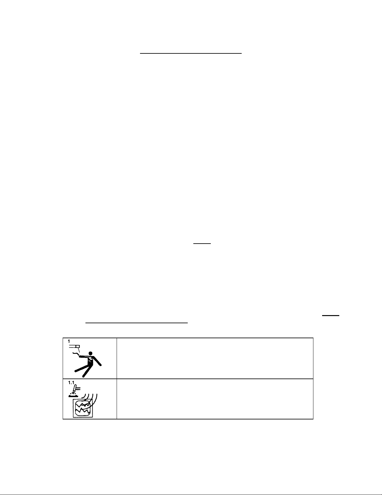
WARNING: Touching energized electrical parts can cause fatal
shocks and burns. When in weld sequence the electrode and work
are electrically energized. Incorrectly installed or improperly
grounded equipment is a hazard.
NOTE
Docume
Revision N
nt No. 740084
WARNING: This equipment is authorized to use a type of arc starter
that produces a High Frequency Radio Wave (sometimes called HF
and/or RF Starting). It can cause interference and sometimes even
damage to nearby electronic equipment (such as computers) that
are un-protected or poorly protected against such interference.
1

Model 415
Operation Manual
WARNING: Magnetic Fields from High Currents can affect
pacemakers. PACEMAKER WEARERS KEEP AWAY UNTIL
CONSULTING YOUR DOCTOR.
WARNING: Disconnect the input power to the machine before
opening or servicing. Discharge all circuits that store high voltage
such as capacitor packs. Only QUALIFIED service personnel should
open this equipment.
WARNING: Welding can cause fires or explosions. Do not weld
near FLAMMABLE or EXPLOSIVE MATERIALS. Watch for fire.
Have the proper type of extinguisher in your work area.
WARNING: Welding Operators should wear non-flammable
protective clothing, footwear and head gear.
WARNING: Never weld on sealed containers or pipes. This may
result in an EXPLOSION.
WARNING: Welding produces high temperatures in both the
welded components and the welding equipment. Both can cause
severe burns. Do not touch recently welded components. Avoid
touching internal components of the welding system soon after use.
Avoid touching torch components and welding fixtures soon after
welding.
WARNING: The welding arc emits ultra-violet (UV) radiation and the
molten weld gives off infra-red (IR). Both can burn eyes and skin if
unprotected. Suitable eye and skin protection must be worn.
WARNING: Weld materials can emit toxic fumes during welding.
WELD ONLY IN AREAS WITH ADEQUATE VENTILATION.
WARNING: Most GTAW gases like Argon are non-toxic, however,
Argon is heavier than air and will displace the normal atmosphere in
enclosed areas. DO NOT WELD IN ENCLOSED AREAS WITH
OUT PROPER VENTILATION OR RESPIRATORS.
e
Docum
Revision N
nt No. 740084
2
Model 415
Operation Manual
WARNING: AMI factory training is essential for all Welding
Operators and Maintenance Technicians who operate AMI
equipment.
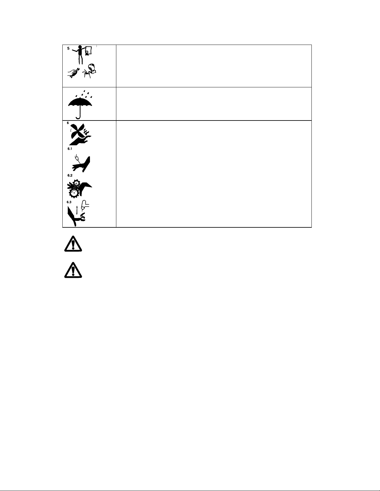
WARNING: Before operating, storing or handling, always make sure
that the M-415, M-415 Pendant, weld heads and cables are not
exposed to rain or standing water. SYSTEM COMPONENTS ARE
NOT WEATHER-PROOF.
WARNING: Keep hands and fingers clear from moving parts such
as fans, gears rotors, Wire Feed, Rotation and AVC Mechanisms.
WARNING: The M-415 Power Supply is not intended for pipe thawing or heating in any
form.
WARNING: The M-415 Power Supply weighs in excess of 700 lb. (317.5 kg). Be sure to
follow your local, OSHA, international and employer guidelines for proper methods of handling and
re-locating this equipment.
1.2 OPERATIONAL PRECAUTIONS
The following is a check list for operating personnel to follow to insure minimum system down-time
due to improper operation and handling:
1. To AVOID severe equipment damage VERIFY that the M-415 is connected to the correct
Input AC power (see section 3.4).
2. Before operating, check all fittings and connectors for proper seating and that all protective
boots are in place. If not properly seated or protected, short circuits, poor connections or
inert gas leaks could occur.
3. The M-415 is intended for typical GTAW gases ONLY. NEVER CONNECT OXYGEN OR
ACETYLENE TO THE M-415.
4. Before operating, insure that all cables are routed or protected in such a way that they will
not be subject to heat, equipment and/or personnel traffic. Insure that the cables DO NOT
come in contact with HOT PIPE.
5. When storing or handling cables, always keep the protective boots and dust caps on all
connectors and fittings until ready to install. A major cause of downtime in any automatic
welding system is improper care and use of cables.
e
Docum
nt No. 740084
Revision N
3

Model 415
Operation Manual
6. Before operating, insure that the M-415 has adequate air flow. Do not restrict the intakes or
exhaust vents of the power supply.
7. Before operating, always insure that there is bare metal contact between the weld head
components which connect to GROUND (clamp inserts, etc.) and the tube or pipe to be
welded.
8. When storing or handling weld heads, always keep them in the protective containers they are
shipped in, or optional carrying case, until ready to install.
9. When operating, storing or handling, insure that the system is protected against dirt, dust,
etc. NEVER GRIND NEAR AN EXPOSED WELD HEAD OR THE M-415.
10. Do not use acid, corrosives, liquid “Easy Out” or any liquid substance on the M-415 or any
AMI weld head. When cleaning, use only a light solution of Isopropyl alcohol on a soft cloth .
11. When handling, take extreme care to avoid dropping the M-415, weld heads, cables or any
accessories.
12. Do not attempt to move tube end into position using the weld head as a lever.
13. Do not add any lubrication like graphite, oil or grease to the weld heads or power supply
unless it is specified in the operation or maintenance manual for that equipment.
1.3 RF AND EMI EMISSIONS
1. WHY RF?
“It has long been recognized that in the practice of welding and cutting, there are
circumstances where it is required to assist the process using radio frequency voltage. In
order to arc weld an electric arc must be created, because of safety and economic concerns,
the no load voltage of arc power sources is kept as low as practical. Thus, a source of high
voltage with a high safety factor must be utilized. Radio Frequency voltage is the best
method of meeting these criteria for many reasons” (quoted from CISPR/B/63).
2. RF REGULATION
The FCC regulates the RF emission limitations for welding equipment by the use of an IEC
(international) regulation created by the Special Committee on Radio Interference (known
as CISPR) subcommittee B. The regulation of record is: CISPR/B/63
“CODE OF PRACTICE FOR THE USE OF WELDING AND CUTTING POWER SOURCES
UTILIZING RADIO FREQUENCY VOLTAGE FOR STARTING OR STABILIZING THE
ARC.”
The regulation states that due to the variety of work requirements and conditions it is
virtually impossible to establish fixed, normalized and predictable tests and test setups for
RF limits that would actually mean something. Instead of limits they state the following:
“The manufacturer must design and produce equipment that is functional but at the same
time, design this equipment to keep electromagnetic radiation at a minimum.”
“The user has the responsibility to install and use the power source per the instructions of
the manufacturer. Through this practice, it is reasonable to assume that the probability of
electromagnetic disturbances will be significantly reduced. However, if some electromagnetic
disturbances are felt, then it is the responsibility of the USER of the equipment to resolve
the situation.”
Docume
Revision N
nt No. 740084
4

Model 415
Operation Manual
3. RF PROTECTION
AMI policy is to comply with the IEC (and thus FCC) regulations. Our design rules and
procedures include testing and observing this area. We can assure our customers that
every effort has been made to reduce RF emissions to the absolute minimum from our power
sources.
However, this does not mean that a user will not have occasional problems with RF
interference with other equipment due to the use of our equipment. This is the nature of RF
starting.
Most RF noise interference problems are going to be either set-up related or caused by poor
or no filtering on the behalf of the equipment that is being disrupted. Most interference
problems are easily correctable but each one must be looked at on a “case by case basis.”
The M-415 is equipped with a heavy-duty Pi-Network filter, connected to the input power
line, to prevent propagation of EMI either into or out of the M-415. The all-metal enclosures
and internal shields prevent radiated EMI.
1.4 SHOCK HAZARD WARNING
As already stated in this manual “High Voltage” is present on exposed internal terminals. The
ELECTRODE (tungsten) and tube weld head rotors (M-8, M-9) are also an “exposed terminal” and
by its nature the GTAW process requires electrical potential to be present on the electrode during
arc starting and of course during the welding.
All AMI Power Supplies contain a “bleeder” circuit to ground any residual potential after welding or
after an aborted or bad “arc start” attempt. However, these circuits take a few seconds to operate
or COULD FAIL. Do not depend on them to prevent electrical shock.
“THE ELECTRODE SHOULD ALWAYS BE CONSIDERED A POSSIBLE SHOCK HAZARD”.
This is especially true when ever the system is in “weld sequence” ready to weld, is welding, or
has just finished welding. However, equipment/component failure, system abuse, or improper
maintenance could result in electrical potential at the weld head “even when not in weld sequence”.
The users/operators of this equipment must take all precautions necessary to avoid contact with
the ELECTRODE at “ALL TIMES”. The only exception is when actually replacing or adjusting the
electrode and this should be done “WITH THE POWER TURNED OFF”.
If performed with the power “ON” the system must be in test mode out of weld sequence and the
USER MUST OBSERVE COMMON SAFETY PRACTICES such as grounding the electrode to
insure discharge before actually touching it. REMEMBER, there is a “POSSIBLE” shock hazard in
all welding power supplies at “ALL” times.
Most AMI Power Supplies feature High Frequency (HF) Arc Starting. This is a High Voltage/High
Frequency electrical transmission process. To eliminate any HF shock possibility “AVOID ALL
CONTACT” with the Welding WORK (ground), the ELECTRODE or the WELD HEAD during arc
start.
4. EMI SUPPRESSION
Docume
nt No. 740084
Revision N
5
Model 415
Operation Manual
SECTION II - SPECIFICATION
The following contains only general specifications about the M-415 Power Supply. More detailed
information is available in AMI Specification No. 415.
2.0 ELECTRICAL
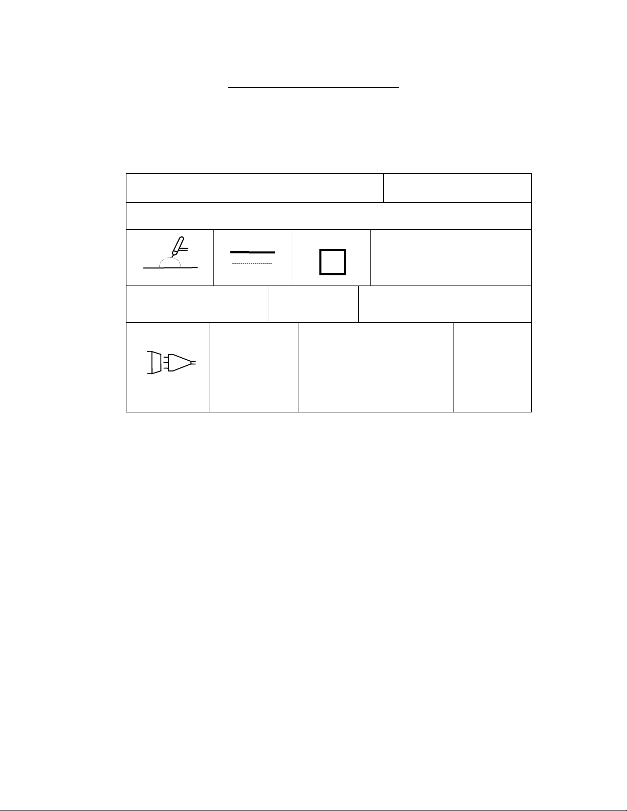
1. RATING PLATE DEFINITIONS
1) Company: Country:
ARC MACHINES, INC. USA
4)
3) Model:
Model 415
S/N: DATE:
8) Process:
G.T.A.W.
9) Output:
Minimum Maximum
5A / 5V 400A / 30V
15) Input:
3~ 50/60 HZ
1) - Manufacturer and Country of Origin.
3) - Model Number Rating Plate applies to.
4) - Serial Number and Date of Manufacture.
6) - International and USA Standards that the equipment meets.
8) - Weld Process symbol for GTAW welding.
9) - Rated MIN and MAX Outputs at Continuous Current with no pulsation.
Rated MIN and MAX Outputs when current is pulsing.
10) - Symbol that output is Direct Current (DC) only.
11) - Rated No Load Output Voltage (open circuit voltage) is 61 volts.
12) - The M-415 is a 100 % Duty Cycle for the rated outputs (9).
15) - Input Voltage type contains symbol for three (3) phase Alternating
Current (AC) input at 50 or 60 Hz frequency.
18) - Nominal Input Voltage value is dependent on Transformer type.
M-415s manufactured before January 1999 are listed as: Domestic, or International.
After January 1999 the Universal transformer was released for use in all countries.
19) - Rated maximum current required from the AC supply. Given for both
I
transformer. Consult the rating plate on your Power Supply for actual number.
21) - International Protection (IP) rating. The M-415 is rated IP21 which includes protection
against a limited amount of exposure to rain (does not make it weather proof or
intended for all weather usage).
22)- The M-415 is rated as class I. No symbol is used for class I equipment.
23)- “S” Symbol indicates a welding power source which is suitable for an environment with an
1 maximum (I1max) and I1 effective (I1eff). Plate shown above is for the Universal
increased electric shock hazard.
18) Voltage:
10) Type:
DC
U1 = 200V
U1 = 240V
U1 = 400V
U1 = 440V
U1 = 480V
U
= 575V
1
23) Shock Rating:
S
11) No-load Voltage:
U
= 61V
0
19) Input Current:
I
= 49A I
1max
I
= 44A I
1max
I
= 25A I
1max
I
= 25A I
1max
I
= 20A I
1max
I
= 20A I
1max
6) Standards:
NEMA EW1 IEC 974-1
12) Duty Cycle:
X = 100% ALL RATED OUTPUTS
21) Rating:
= 49A
1eff
= 44A
1eff
= 25A
1eff
= 25A
1eff
= 20A
1eff
= 20A
1eff
IP21
22) Rating:
nt No. 740084
e
Docum
Revision N
6

Model 415
Operation Manual
2. INPUT POWER, DETAIL - The M-415 can have 1 of 3 operating ranges:
Voltage Phase - Freq.
Max Input Current
Required
200 VAC 3 - 50/60 Hz 50 amperes Service
240 VAC 3 - 50/60 Hz 45 amperes Service
400 VAC 3 - 50/60 Hz 25 amperes Service
440 VAC 3 - 50/60 Hz 25 amperes Service
480 VAC 3 - 50/60 Hz 20 amperes Service
575 VAC 3 - 50/60 Hz 20 amperes Service
FOR POWER SUPPLIES MADE BEFORE JANUARY 1999
200 VAC 3 - 50/60 Hz 60 amperes Service
220 VAC 3 - 50/60 Hz 60 amperes Service
380 VAC 3 - 50/60 Hz 40 amperes Service
415 VAC 3 - 50/60 Hz 40 amperes Service
FOR POWER SUPPLIES MADE BEFORE JANUARY 1999
230 VAC 3 - 50/60 Hz 50 amperes Service
240 VAC 3 - 50/60 Hz 40 amperes Service
440 VAC 3 - 50/60 Hz 40 amperes Service
480 VAC 3 - 50/60 Hz 40 amperes Service
3. OUTPUT POWER - Straight polarity, constant current DC regulation intended for GTAW
welding only.
Minimum current Output all cases .................... = 5 Amperes DC
Maximum current Output ................................. = 400 Amperes DC continuous or peak pulse
4. CIRCUIT BREAKER – Also used as ON/OFF switch, is a 60 Amp 3 phase Auto-Trip, with
electrical Emergency Stop function available on the Power Supply, Operators Pendant and
from an Optional External Hard Wire Command.
5. POWER CABLE -25 foot (7.6 m) Neoprene jacketed harmonized CE approved 4 conductor 8
AWG (10mm²) cordage, rated voltage: 500V.
6. STANDARDS - The M-415 is designed and maintained to meet all applicable IEC and ISO
standards as well as all applicable EC Directives.
7. RATED CONDITIONS - The system will meet or exceed the functional ranges and
tolerances stated, provided that the following conditions exist:
1. Input Voltage does not deviate greater than +/- 10% from normal voltage.
2. Ambient operating temperature range is between 0 degree C (32° F) and 40° C (105° F)
3. Arc Voltage at the power supply terminals is equal to or less than 30 volts.
4. All electrical performance is based on maximum weld head distance of 200 feet (61 m)
from the M-415
2.1 PHYSICAL CONSTRUCTION
1. Cabinet material - aluminum and steel
2. Dimensions (basic Power Supply):
Height: 39 inches (990.6 mm)
Width: 26 inches (660.4 mm)
Depth: 36 inches (914.4 mm)
3. Weight: Less than 700 lb. (317.5 kg) depending on configuration
Transformer Type Model 415
Main Circuit Breaker
Universal 60 Ampere-600 VAC
60 Ampere-600 VAC
60 Ampere-600 VAC
60 Ampere-600 VAC
60 Ampere-600 VAC
60 Ampere-600 VAC
International 60 Ampere-415 VAC
60 Ampere-415 VAC
60 Ampere-415 VAC
60 Ampere-415 VAC
Domestic USA 50 Ampere-600 VAC
50 Ampere-600 VAC
50 Ampere-600 VAC
50 Ampere-600 VAC
Docume
nt No. 740084
Revision N
7

Model 415
Operation Manual
2.2 CURRENT OUTPUT
NOTE
The following specifications will, in many cases, reference “User Defined”. User defined means
that the user can set up the actual programmable ranges and functionality of any given function.
For specification purposes this means that no actual function range can be given. Where
applicable only an absolute maximum or minimum are given.
1. Range - 5 to 400 Amperes programmable. Programmable increments can be user
defined in units of 1 or 0.1 amperes.
2. Type - Continuous or pulsed output DC Straight Polarity for GTAW (TIG) welding only.
3. Regulation - Constant Current closed loop servo using second generation high frequency
(60 KHz) series switching regulation.
4. Regulation Response - Response time for correction of current deviation is less than 500
microseconds. Pulsed mode rise time from background current to primary is 1.2 ampere
per microsecond.
5. Regulation Tolerance - +/- 0.5% of programmed setting or +/- 1.0 ampere whichever is
greater.
2.3 ARC VOLTAGE and ARC VOLTAGE CONTROLLER SERVO
1. Open Circuit Output Voltage - 61 VDC
2. Maximum Output Voltage under load - 30 volts (measured at power supply, not at torch)
3. Arc Voltage Controller Range - (measured at the torch)
Minimum - 5 VDC
Maximum - 25 VDC
Actual programmable range is user defined.
4. AVC Motor Output Current Limit - User defined by weld head type in increments of
0.1 Amperes up to a maximum motor drive current limit of 4.0 Amperes.
5. AVC Motor Output Voltage Limit - 35 VDC
6. Regulation - Closed Loop position servo using arc voltage measured at the torch. Intended
for DC permanent magnet type motors only.
7. Regulation Tolerance - +/- 1% of program value or 0.1 VDC, whichever is greater.
Based on primary current only with no current pulsation. Measurable accuracy with the
current pulsing can be affected by the puddle growth and shrinkage.
8. Regulation Response - Variable and programmable.
9. Jogs - Motor servo provides for UP and DOWN motor jogs. Jog speeds are adjustable.
2.4 TRAVEL (torch rotation) SERVO
1. Range - Programmable range is User defined by weld head type. Unit of measure (IPM or
RPM) and increments is user defined by weld head type.
2. Regulation - Closed loop velocity servo using, as standard, analog tachometer feedback
of 0 to 5 VDC. Can be set up to regulate using digital tachometer or digital encoder
feedback. Intended for DC permanent magnet type motors only.
3. Motor Output Current Limit - User defined by weld head type in increments of
0.1 Amperes up to a maximum motor drive current limit of 4.0 Amperes.
4. Motor Output Voltage Limit - 35 VDC
5. Regulation Tolerance - +/- 1% of program value or +/- 0.1 IPM or RPM whichever is
greater. Based on maximum range being at least 10 IPM or RPM.
6. Jogs - Motor servo provides for bi-directional (CW and CCW) motor jogs. Jog speeds are
adjustable.
2.5 WIRE FEED SERVO
1. Range - Programmable range is User defined by weld head type. Unit of measure (IPM or
mm/min) also user defined by weld head type.
2. Regulation - Closed loop velocity servo using, as standard, analog tachometer feedback
of 0 to 5 VDC. Can be set up to regulate using digital tachometer or digital encoder
feedback. Intended for DC permanent magnet type motors only.
Docume
nt No. 740084
Revision N
8

Model 415
Operation Manual
3. Motor Output Current Limit - User defined by weld head type in increments of
0.1 Amperes up to a maximum motor drive current limit of 4.0 Amperes.
4. Motor Output Voltage Limit - 35 VDC
5. Regulation Tolerance - +/- 2% of program value or +/- 1 inch, whichever is
greater. Based on maximum range being at least 100 IPM.
6. Jogs - Motor servo provides for bi-directional (FEED and RETRACT) motor jogs. Jog
speeds are Adjustable.
2.6 TORCH OSCILLATION and CROSS-SEAM STEERING SERVO
1. Range - User Defined by weld head type as to maximum programmable amplitude.
2. Regulation - Closed loop position servo using +/- 5 VDC feedback voltage for
position information. Feedback device varies with weld head model. Intended for DC
permanent magnet type motors only.
3. Motor Output Current Limit - User defined by weld head type in increments of
0.1 Amperes up to a maximum motor drive current limit of 4.0 Amperes.
4. Motor Output Voltage Limit - 35 VDC
5. Regulation Tolerance - +/- 1% of program value or 0.010 inches, whichever is greater.
Based solely on M-415 servo specification. Actual response speed and tolerance
performance can vary depending on the dynamic loads on the weld head. Consult the
weld head specification for each weld head tolerance.
6. Jogs - No jogs are provided. Oscillator is continually seeking desired position. Position
is based on input (steering) commands from steering devices (on Pendant and Display).
2.7 TIMING FUNCTIONS
1. Purge Time Range (pre and post) -
000 to 1000 seconds. User can define minimum programmable time.
2. Start Delay Time Range (Travel, Wire, AVC) -
00.0 to 100 seconds in increments of 0.1 seconds.
3. Stop Delay Time Range (Travel, Wire, AVC) -
00 to 100 seconds.
4. Upslope Time Range -
00.0 to 100 seconds. User can define minimum programmable time
5. Downslope Time Range -
00 to 100 seconds. In increments of 1 second
6. Weld Level Time Range (up to 99 levels) -
0000 to 10000 seconds.
7. Pulse Timing Range (Primary/Background) -
0.00 to 100 seconds in increments of 0.01 seconds.
8. Oscillator Timing Range (Dwells and Excursion) -
0.00 to 100 seconds in increments of 0.01 seconds.
9. Primary WF pulse delay -
0.00 to 100 seconds in increments of 0.01 seconds.
10. Timing Resolution -
+/- 0.01 seconds (all timing functions)
2.8 ARC STARTING
1. Starting Methods - Touch or RF (radio frequency)
2. Touch Start provides a smooth, consistent and tungsten inclusion free start with any weld
head that has an AVC. Touch and Retract speeds are user defined. User can set up for
single start attempt or multiple start attempt.
3. RF Starting provides a method of arc starting without the electrode touching the weld
surface. System is designed for best performance under the following conditions:
1. Minimum first level primary current - 5 Amperes (in Argon only)
2. Gases - Argon, 95/5 Argon/Hydrogen, Helium or Helium/Argon Mixes.
3. 1 atmosphere pressure. Consult factory for operation in pressure chambers.
4. Maximum arc gap - 0.156 inch (4 mm)
Docume
nt No. 740084
Revision N
9

Model 415
Operation Manual
5. Cerriated or Thoriated Electrodes with conventional grinds.
6. Cable lengths up to 200 feet.
7. Multiple arc strike attempts.
2.9 TORCH COOLING UNIT - Liquid cooled, forced air heat exchanger with coolant reservoir.
1. Reservoir Capacity - 2.5 gallons (9.46 liters)
2. Maximum Pressure - 60 PSI
3. Flow - 0.3 GPM for 400 Ampere Torches.
0.2 GPM for 300 or less Ampere Torches
4. Head - Up to 100 feet with 200 feet of cable.
5. Duty Cycle - 100 %
6. Distilled or Demineralized Water coolant, (see section 3.3 for use where freezing may occur).
7. Replaceable coolant filter
8. Pressure relief valve and by-pass built-in
2.10 GAS DISTRIBUTION SYSTEM
1. Control - Electrical Solenoid valve.
2. Pressure - Maximum 50 PSI
3. Flow - 5 to 100 CFH
Docume
nt No. 740084
Revision N
10

Model 415
Operation Manual
3.0 INSTALLATION, GENERAL
The Model 415 Power Supply is designed to provide reliable and repeatable performance within its
specified limits. The Model 415 is also, by its nature, something that must be relocated from time to
time and be installed, by the user, without Factory Service being required. Because of this,
assurance that the Model 415 is working within its specified limits is a “user
begins with INSTALLATION.
This Section of the Operation Manual provides the requirements and procedures for the proper
installation and initial turn on of the Model 415.
3.1 TRAINING
The Model 415 is designed to be as easy as possible to install and operate. The instruction of this
manual should, in most cases, supply the user with the information needed for Installation and
Operation. However, automatic welding systems can be complicated and Arc Machines, Inc.
“STRESSES
” the need for complete FACTORY training involving Installation, Operation,
Programming and Maintenance.
This manual does not attempt to cover all possible problems, deviations or usage of the Model
415. In this Manual, where these items might occur, a general instruction is given to consult a
Factory Representative.
3.2 INSPECTION
The M-415 is shipped new, in a re-usable and factory approved shipping container. This container
should be retained and stored carefully in order to re-use in case of a need to re-ship the M-415 to
another location.
1. After unpacking, inspect all items for obvious physical damage and loose parts. If damage is
evident, contact a factory representative before using. If water condensation is apparent, dry
the unit before using.
2. All M-415’s are shipped with a variety of peripheral equipment such as gas hoses, fittings,
manuals (including this one) and electrical drawings. An exact list of these items is included
with each power supply shipment. This manual will reference some of those items, so before
beginning installation, these items should be located and be available.
3. Inspect the Power Supply Cabinet (See Figure 1, Item 1)
1. Perform an exterior visual inspection looking for obvious physical problems such as
broken connectors, dents or loose components.
2. There are two Connect Panels on the left side of the Cabinet. These are the Electrical
- I/O Connect Panel (left side upper) and the Weld Head Connect Panel (left side rear).
Insure that all Protective Dust Covers and Retaining Chains are installed on all electrical
multi-pin Connectors (See Figure 1, Item 2).
3. Remove both the left and right hand SIDE PANEL Retaining Screws and remove the
SIDE PANELS (see Figure 1, Item 3, 13). Leave the SIDE PANELS off until the end of
Section Step 3.4.
4. Visually inspect the interior for obvious physical problems such as loose components,
dangling wires, foreign (loose) objects, excessive dirt or any standing water,
condensation or moisture.
5. Note the location of the main transformer and tap setting Terminal Strip (See Figure 1,
Item 4). This will be set up in Section 3.4.
SECTION III - INSTALLATION
NOTE
” responsibility and it
Docume
nt No. 740084
Revision N
11
 Loading...