


205 WDR

Model 205 Tube Welding Power Supply
Part No. 740108
Revision J
Operator’s Manual

M O D E L 2 0 5
T
O P E R A T O R ’ S M A N U A L
INTRODUCTION
he Model 205 is a power source and controller for automatic orbital tube welding. It is
intended to be used only in conjunction with AMI or EXEL orbital tube weldheads.
The Model 205 power supply provides GTAW (Gas Tungsten Arc Welding) current
with pulsation controls, high frequency arc starting, purge gas controls, weldhead arc
rotation and automatic timing functions. Users need only to supply input AC power, a
regulated gas source with flow meter and the appropriate weldhead.
NOTICE
This document and the information contained herein is the property of Arc Machines, Inc. It
is proprietary and submitted and received in confidence. It shall be used only for the
purpose for which it is submitted and shall not be copied in whole or in part without the prior
express written permission of Arc Machines, Inc. The information in this document has
been carefully reviewed and is believed to be accurate. However, no responsibility is
assumed for inaccuracies.
Information and instructions in this document are subject to change and Arc Machines, Inc.
reserves the right to change specifications and data without notice.
i

M O D E L 2 0 5
O P E R A T O R ’ S M A N U A L
Revision History
Rev ECO No.
Change Description Date Appr.
A N/A Initial release 3/10/09 B.F.
B 5355 Update sections 2.0, 3.0, 4.0, 5.0 & 6.0; delete Glossary 5/14/09 B.F.
C 5411 Update section 4.10.9 Performing a Weld 07/06/09 B.F.
D 5447 CE changes 12/30/09 D.C.
E 5713 Correct table in Section 6.1.2 with correct weight 06/16/10 D.C.
F 5817 Incorporate S/W v1.5, corrections for CE changes, add
12/08/10 D.C.
power grounded to section 2.0, update obsolete data
G 6346 Incorporate M21 W/H information, add changes to Run
06/15/12 D.C.
screen, add Associated Data look-up tables, add
information on system initiate 0.5 second delay, add
information on +1%/-1% buttons, update UK address.
H 6518 Section 6.2, changed picture of Remote Pendant (pg51) 3/20/13 BL
J 6646 Add Weld Data Recording functionality and update
2/25/14 W.O.
applicable screens
ii
ii
iiii

M O D E L 2 0 5
O P E R A T O R ’ S M A N U A L
Table of Contents
Table of Contents
Table of ContentsTable of Contents
INTRODUCTION.................................................................................................... i
NOTICE..............................................................................................................i
Revision History ............................................................................................ii
Table of Contents .........................................................................................iii
1.0 SAFETY PRECAUTIONS...................................................................... 1
1.1 SHOCK HAZARD WARNING................................................................ 1
1.2 WARNING LABEL DEFINITIONS ......................................................... 3
2.0 SPECIFICATIONS .................................................................................5
2.1 ELECTRICAL ........................................................................................ 5
2.2 ELECTICAL SERVICE GUIDE .............................................................. 6
2.3 PHYSICAL DIMENSIONS .....................................................................6
2.4 PROGRAMMABLE AND OPERATIONAL FUNCTIONS ...................... 7
3.0 INITIAL SETUP......................................................................................8
3.1 SYSTEM SYMBOLS..............................................................................8
3.2 INSPECTION .......................................................................................10
3.3 POWER CONNECTION....................................................................... 11
3.4 WELDING GAS CONNECTIONS ........................................................ 11
3.5 MODEL 205 TO M8 / M9 WELDHEAD HOOK UP ..............................12
3.6 MODEL 205 TO EXEL ROTOR DRIVER HOOK UP........................... 16
3.7 MODEL 205 TO M21 WELDHEAD HOOK UP ....................................17
4.0 OPERATION........................................................................................ 18
4.1 SYSTEM FUNCTIONS......................................................................... 18
4.2 INITIAL POWER ON............................................................................20
4.3 SET-UP FUNCTIONS ..........................................................................21
4.4 OPENING THE LAST WELD SCHEDULE ..........................................25
4.5 SELECTING A WELD SCHEDULE FROM THE LIBRARY ................25
4.6 MODIFY A WELD SCHEDULE ...........................................................26
4.7 COPY A WELD SCHEDULE ...............................................................30
4.8 CREATE A WELD SCHEDULE........................................................... 33
4.9 WELDHEAD CALIBRATION...............................................................35
4.10 PERFORMING A WELD.....................................................................36
4.11 WELD DATA RECORDING................................................................40
5.0 MAINTENANCE AND TROUBLE-SHOOTING ................................... 43
6.0 OPTIONS.............................................................................................52
iii
iii
iiiiii
M O D E L 2 0 5
Hazard
Chapter
1
O P E R A T O R ’ S M A N U A L
1.0 SAFETY PRECAUTIONS
The Model 205 is intended to be used only with AMI or EXEL weldheads for the purpose of
GTAW welding of metal tube. The system is not to be used for any other purpose, specifically
heating or cutting.
WARNING
I C O N K E Y
Warning
Electrical
THAT HE HAS READ AND/OR BEEN MADE AWARE OF ALL OF THE SAFETY-RELATED
ITEMS CONTAINED IN THIS MANUAL.
The nature of the GTAW process creates some POTENTIAL
HAZARDS. In accordance with international safety regulations the
EXCLAMATION SYMBOL indicates that this equipment is considered
HAZARDOUS. The LIGHTNING FLASH SYMBOL indicates that
there are potential electrical hazards. The use and display of these
symbols make it the OPERATOR’S RESPONSIBILITY TO ENSURE
1.1 SHOCK HAZARD WARNING
HIGH VOLTAGE is present on exposed internal terminals. The ELECTRODE (tungsten /
weldhead rotor) is also an EXPOSED TERMINAL and by its nature the GTAW process requires
electrical potential to be present on the electrode during arc starting and during welding.
1
M O D E L 2 0 5
O P E R A T O R ’ S M A N U A L
All AMI Power Supplies contain a “bleeder” circuit to ground any residual potential
after welding or after an aborted or bad arc start attempt. These circuits take a few seconds
to operate or could fail.
The electrode should always be considered a possible shock hazard. This is
especially true when the system is in “weld sequence”, ready to weld, is welding or has just
finished welding. Equipment/component failure, system abuse or improper maintenance
could result in electrical potential at the weldhead even when not in “weld sequence”.
The users/operators of this equipment must take all precautions necessary to avoid
contact with the ELECTRODE at “ALL TIMES”. The only exception is when actually
replacing or adjusting the electrode and this should be done WITH THE POWER TURNED
OFF.
If performed with the power “ON” the system must be in “TEST” mode out of weld
sequence and the USER MUST OBSERVE COMMON SAFETY PRACTICES such as
grounding the electrode to ensure discharge before actually touching it.
Most AMI Power Supplies feature High Frequency (HF) Arc Starting. This is a High
Voltage/High Frequency electrical transmission process. To eliminate any HF shock
possibility “AVOID ALL CONTACT” with the Welding WORK (ground), the ELECTRODE or
the WELDHEAD during arc start.
Remember, there is a possible shock hazard in all welding power supplies at
ALL times.
2222
M O D E L 2 0 5
O P E R A T O R ’ S M A N U A L
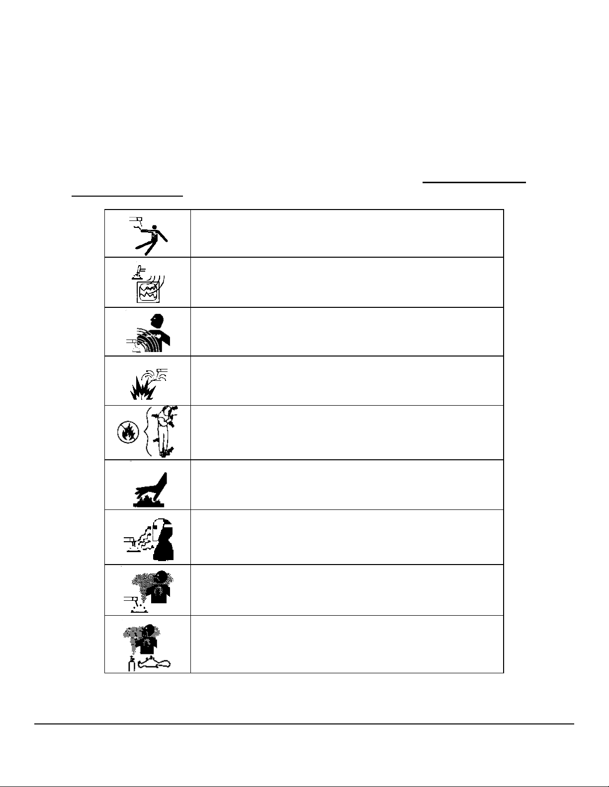
1.2 WARNING LABEL DEFINITIONS
The table below contains caution and warning labels for the operation of this equipment. Before
operating this or any welding equipment users should be familiar with ANSI-49.1 Safety in
Welding and Cutting.
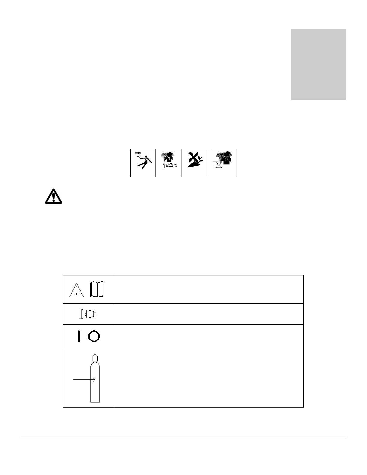
ELECTRIC SHOCK from welding electrode or wiring can kill.
HIGH FREQUENCY RADIO WAVES can cause interference and
sometimes even damage to nearby electronic equipment (such
as computers) that are un-protected.
MAGNETIC FIELDS can affect implanted medical devices.
Wearers of pacemakers should keep away until consulting their
doctor.
Welding can cause FIRE OR EXPLOSIONS. Do not weld near
FLAMMABLE or EXPLOSIVE MATERIALS. Have the proper
type of extinguisher in the work area.
WEAR NON-FLAMMABLE protective clothing, footwear and
head gear at all times.
HOT PARTS can cause severe burns. Do not touch recently
welded components. Avoid touching torch components and
welding fixtures soon after welding.
ARC RAYS can burn the eyes and skin. The welding arc emits
ultra-violet (UV) radiation and the molten weld gives off infra-red.
Both can burn eyes and skin if unprotected. Suitable eye and skin
protection must be worn.
BUILD UP OF GAS can injure or kill. Weld materials can emit
toxic fumes during welding. WELD ONLY IN AREAS WITH
ADEQUATE VENTILATION.
FUMES AND GASES can be hazardous. Welding produces
fumes and gases. Breathing these fumes and gases can be
hazardous to your health. DO NOT weld in enclosed areas
without proper ventilation or respirators.
3333
M O D E L 2 0 5
O P E R A T O R ’ S M A N U A L
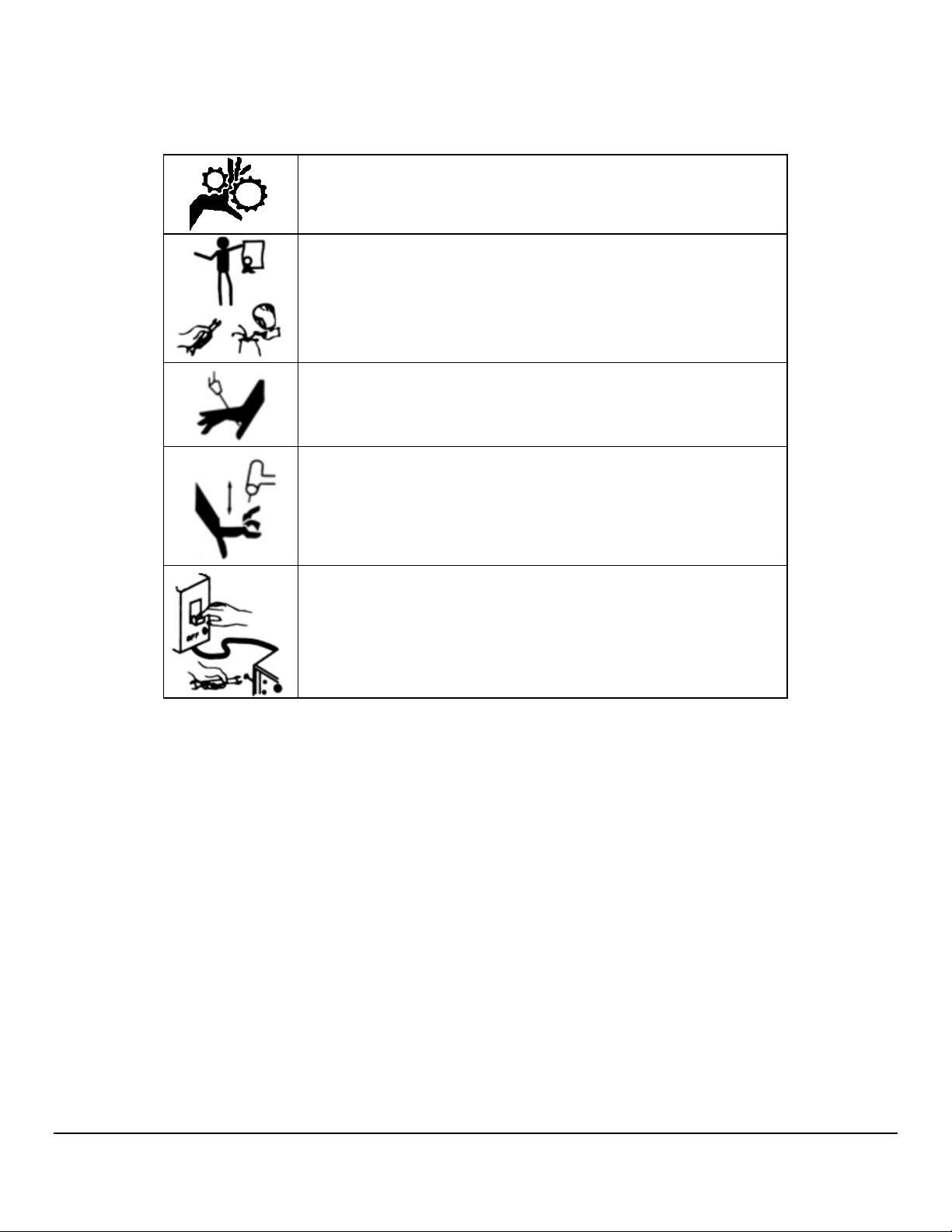
MOVING PARTS - Keep hands and fingers clear of fans,
gears, rotors, wire feed, rotation and AVC mechanisms
WARNING: AMI factory training is essential for all Welding
Operators and Maintenance Technicians who operate AMI
equipment.
WELDING WIRE and ELECTRODES are sharp and can cause
injury.
MOVING PARTS may cause crush or pinch points.
WARNING: Disconnect the input power to the machine before
opening or servicing. Discharge all circuits that store high
voltage such as capacitor packs. Only AUTHORIZED and
QUALIFIED service personnel should open this equipment.
4444

M O D E L 2 0 5
90V
90V
90V
90V
Chapter
2
O P E R A T O R ’ S M A N U A L
2.0 SPECIFICATIONS
These specifications pertain the to Model 205 power supply only. For weldheads, refer to the
specification sheet of each particular model. For non-AMI supplied equipment such as gas
tanks and regulators, refer to the original manufacturer’s documentation.
The Model 205 is a mobile system that is intended be hand carried. The supporting equipment
such as weldheads, water coolers, gas regulators, remote controls and extension cables can
also be hand carried. Items such as gas tanks and welding fixtures should be moved with
appropriate equipment and safety precautions. Gas tanks should be securely anchored to
prevent toppling over.
2.1 ELECTRICAL
INPUT POWER DETAIL
The Model 205 can operate on the following Auto Adjusting for Single Phase AC input:
Input Power
Single-Phase
AC
115 Volts TIG
20A
230 Volts TIG
20A
Rated Welding
Output
100A @ 14.0
Volts DC, 100%
Duty Cycle
150A @ 16.0
Volts DC, 30%
Duty Cycle
100A @ 14.0
Volts DC, 100%
Duty Cycle
150A @ 16.0
Volts DC, 30%
Duty Cycle
Welding
Amperage
Range
5 - 150A
5 - 150A
5 - 150A
5 - 150A
Max OCV
DC (Up)
12-16
12-16
12-16
12-16
Rated Peak
Starting
Voltage (Up)
15 KV 18.4 2.1 2.1
15 KV 28 3.4 3.1
15 KV 8.3 2 1.9
15 KV 14.2 3.2 3.1
Amperes Input
At Rated Load
Output, 50/60Hz,
Single-Phase
KVA
@
Duty
Cycle
KW
Input power must be grounded.
5555

M O D E L 2 0 5
O P E R A T O R ’ S M A N U A L
OUTPUT POWER
Straight polarity, constant current DC regulation intended for GTAW welding only. Static
characteristic of all power supplies is flat.
5 to 150 amperes DC using 100 to 120 VAC input.
5 to 150 amperes DC using 200 to 240 VAC input.
CIRCUIT BREAKER – ON/OFF, two pole, 20 Ampere at 250 VAC.
DUTY CYCLE – determined by the AC input voltage and the required output current. The
Model 205 system has an internal thermal sensor that will limit operation should the
temperature exceed the safe operating parameters.
2.2 ELECTICAL SERVICE GUIDE
FUNCTION RANGE
INPUT VOLTAGE 115/230
INPUT AMPERES AT RATED OUTPUT 13.1
MAX RECOMMENDED STD FUSE RATING IN AMPERES
• CIRCUIT BREAKER, TIME DELAY
• NORMAL OPERATING
15
20
MIN INPUT CONDUCTOR SIZE IN AWG 14
MAX RECOMMENDED INPUT CONDUCTOR
LENGTH IN FEET (METERS)
91 (28)
MIN GROUNDING CONDUCTOR SIZE IN AWG 14
2.3 PHYSICAL DIMENSIONS
POWER SUPPLY HEIGHT 18” (457mm)
POWER SUPPLY WIDTH 19” (483mm)
POWER SUPPLY DEPTH 14” (356mm)
POWER SUPPLY WEIGHT 51 lbs (22 kg)
6666

M O D E L 2 0 5
O P E R A T O R ’ S M A N U A L
2.4 PROGRAMMABLE AND OPERATIONAL FUNCTIONS
SINGLE ENTRY FUNCTIONS
FUNCTION RANGE
PREPURGE 5.0 – 999.0 seconds
POSTPURGE 5.0 – 999.0 seconds
UPSLOPE 0.0 – 99.9 seconds
START LEVEL 5.0 – 150.0 amps
DOWNSLOPE 00.0 – 99.9 seconds
LEVEL ADVANCE TIME / POSITION
TRAVEL START DELAY 00.0 – 99.9 seconds
TRAVEL DIRECTION CW / CCW
MULTI-LEVEL FUNCTIONS
The following functions can be programmed at each level to change value during a
given weld sequence.
FUNCTION RANGE
LEVEL POSITION 0 – 9999 degrees
LEVEL DEGREES 0 – 9999 degrees
SLOPE DEGREES 0 – 9999 degrees
TIME 0.1 – 999.9 seconds
SLOPE TIME 0.0 – 999.9 seconds
PRIMARY AMPS * 5.0 – 150.0 amps
BACKGROUND AMPS 5.0 – 150.0 amps
PRIMARY TRAVEL As defined by Weldhead **
BACKGROUND TRAVEL As defined by Weldhead **
PRIMARY PULSE 0.01 – 9.99 seconds
BACKGROUND PULSE 0.01 – 9.99 seconds
PULSE MODE ON / OFF
TRAVEL MODE ON / STEP / CONT
* For single level schedules the PRIMARY AMPS function is replaced by START AMPS and
END AMPS functions
** TRAVEL functions are in 0.01 RPM increments
7777
M O D E L 2 0 5
Chapter
3
O P E R A T O R ’ S M A N U A L
3.0 INITIAL SETUP
This manual is intended to assist users of this equipment in set up and basic
operation. It is NOT INTENDED AS A SUBSTITUTE FOR FACTORY TRAINING.
3.1 SYSTEM SYMBOLS
The following symbols are present on the Model 205 version 13B050100-02
Revision NC and up:
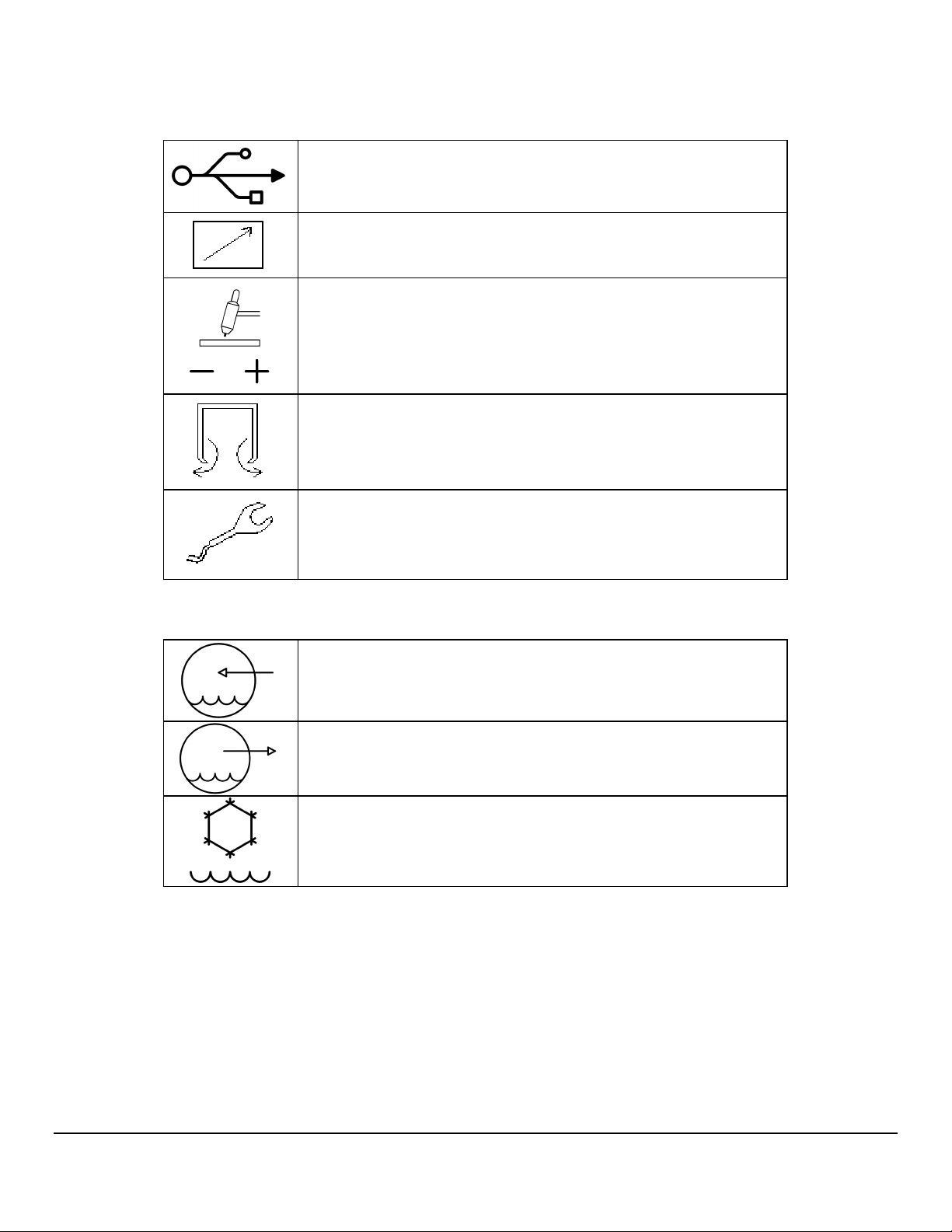
WARNING: Read this manual! This document contains
information that could help prevent injury or damage to the
equipment.
115/230 VAC INPUT - AC mains input, 100-240 volts AC,
50/60 Hz.
ON OFF - On/Off switch (circuit breaker).
ARC GAS INPUT - input for the arc shielding gas. An external
regulator and flow indicator must be used.
8888
M O D E L 2 0 5
O P E R A T O R ’ S M A N U A L
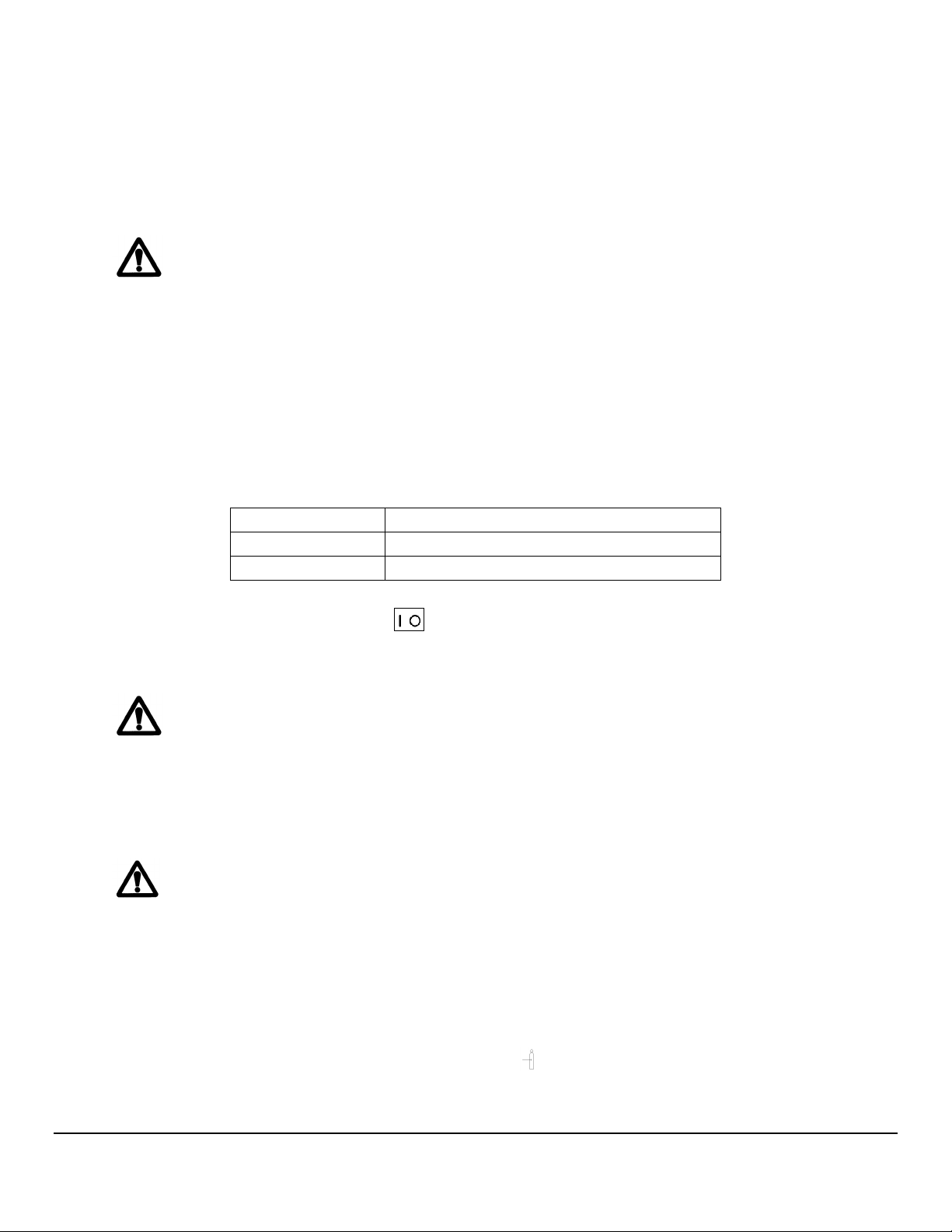
USB - USB port. Devices should not be left plugged in while
welding.
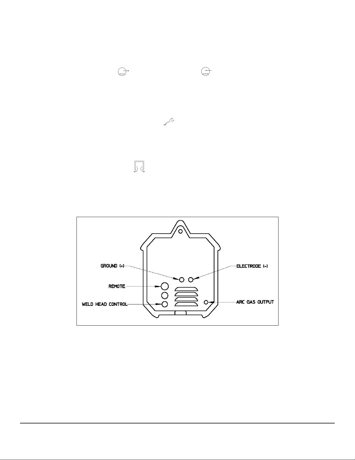
REMOTE - Remote control connection
GROUND(+) ELECTRODE(-) - weldhead ground and electrode
connections.
ARC GAS OUTPUT - output for the arc shielding gas connection.
WELDHEAD CONTROL - weldhead motor control. Intended for
AMI and EXEL weldheads only.
The optional water cooler M205-CW is marked with the following symbols:
WATER RETURN - cooling water input.
WATER OUT - cooling water output.
Cooling liquid tank fill opening.
9999

M O D E L 2 0 5
O P E R A T O R ’ S M A N U A L
3.2 INSPECTION
The Model 205 is shipped with a variety of peripheral equipment such as gas hoses, fittings and
cables. An exact list of these items is included with each power supply shipment and should be
located prior to setup.
• After unpacking, inspect all items for obvious physical damage and loose parts. If
damage is evident, contact a factory representative before using. If water
condensation is apparent, dry the unit before using.
• Check all fittings and connectors for proper seating and ensure that all protective
boots are in place. If the unit is not properly seated or protected short circuits, poor
connections or inert gas leaks could occur.
• Ensure that all cables are routed and protected in such a way that they will not be
subject to heat or equipment / personnel traffic. Ensure that the cables DO NOT
come in contact with HOT PIPE.
• For operation the Model 205 must be placed on a flat level surface capable of
supporting the weight of the unit, cables, and any other options. The Model 205
can be mounted on top of the optional water cooler provided the installation will
not cause the unit to topple over.
• Check the gas and coolant hoses (if used) to ensure that they are not pinched or
bent as this will restrict flow.
• Ensure that the Model 205 has adequate air flow and the intakes and exhaust vents
are not restricted.
• Ensure that there is bare metal contact between the weldhead components which
connect to GROUND (clamp inserts, etc.) and the tube to be welded.
10
10
1010
M O D E L 2 0 5
O P E R A T O R ’ S M A N U A L
3.3 POWER CONNECTION
To avoid severe equipment damage ensure that the Model 205 power supply is
connected to the correct input AC power as listed in Section 2.0 Specifications.
The Model 205 can operate on any single phase voltage from 100V AC to 240V AC.
Provided the input voltage is within this range, the unit will automatically adjust for the input
voltage.
1. The Model 205 is supplied with a 15 foot power cord. A suitable AC line connector
matching the input power must be supplied and installed by the user. Color coding of
the power cord is as follows:
Green/Yellow: Equipment grounding conductor
White/Gray: Grounded circuit conductor, Neutral
Black: Ungrounded circuit conductor, Line
2. Ensure that the circuit breaker is in the down or OFF position.
3. Connect the AC line connector to the power cord.
Do not connect the Model 205 to the AC power source until all installation
steps are complete
3.4 WELDING GAS CONNECTIONS
The Model 205 is intended for typical GTAW gases ONLY. NEVER CONNECT
OXYGEN OR ACETYLENE TO THE MODEL 205.
1. The Arc Gas hose is supplied with the Model 205. This hose is made of material
selected specifically for automatic welding. HOSES MADE FROM OTHER
MATERIAL ARE NOT RECOMMENDED (especially rubber, nylon, or tygon).
2. This 10 foot (3 meter) hose should be installed from the gas regulator/flow meter
(user supplied) to the ARC GAS INPUT fitting on the Model 205. The hose is
supplied with the fittings required to mate with the Model 205 and most domestic
(USA) inert gas flow meters.
11
11
1111
M O D E L 2 0 5
O P E R A T O R ’ S M A N U A L
3. The arc gas is controlled by a solenoid and flow sensor in the Model 205. Attach the
input gas line to ARC GAS INPUT fitting on the Model 205, NOT DIRECTLY TO
THE WELDHEAD.
4. Attach the other end of the input gas hose to the gas regulator/flow meter. Fitting it
loosely by hand, tighten the nut slightly with a wrench to ensure there are no leaks.
DO NOT OVER TIGHTEN. The use of plumbers tape or grease is NOT
RECOMMENDED.
The Model 205 arc gas solenoid valve is rated at 50 PSI (345 kPa) maximum
pressure, DO NOT EXCEED THIS RATING.
3.5 MODEL 205 TO M8 / M9 WELDHEAD HOOK UP
Always turn the power supply off before making any cable or connection
changes to the power supply.
Non-liquid-cooled weldheads (Models 9-250 and 9-500) connect directly to the Model
205. Liquid-cooled weldheads connect to the Model 205 via a short pig-tail or via an
adapter cable. If needed an extension cable can be used. The extension cable
connects to the Model 205, then to the weldhead for non liquid-cooled weldheads or to
the adapter cable for liquid-cooled weldheads.
Pig-tail Connections
1. Connect the ground and electrode brass quick-disconnect fittings on the pig-tail to
the mating fittings on the weldhead. Pull the knurled ring on the female fitting back
and fully insert the male fitting. These connectors are fully seated when the ring will
spring back to its original position. Slide the rubber boots together and secure them
in place, being careful not to dislodge the connectors. Male boots should cover the
connection first. The boots protect the connectors and prevent shorting to ground.
2. Attach the ground and electrode connectors on the pig-tail to their respective
GROUND(+) and ELECTRODE(-) terminals on the Model 205. Align the
keyways, push in and turn clockwise until fully locked.
12
12
1212

M O D E L 2 0 5
O P E R A T O R ’ S M A N U A L
3. Insert the two coolant line quick-disconnect fittings on the pig-tail into the mating
WATER OUT and WATER RETURN connectors on the Model 205-CW.
These connectors are interchangeable so either connector may be connected to
either mating fitting. To prevent accidental disconnection after making the
connection, finger-tighten the lock screw on the male connectors.
4. Attach the weldhead control male connector on the weldhead to the WELDHEAD
CONTROL connector on the Model 205. Note the positioning keyway and
NEVER FORCE or use tools on the cable connectors. Hand-tighten the connecting
ring being careful not to cross-thread the ring.
5. Insert the male gas quick-disconnect fitting on the weldhead to the mating ARC GAS
OUTPUT connector on the Model 205 and hand-tighten the lock screw to
prevent accidental disconnection. Slide the rubber boot over the connection.
Adapter Cable Connections
1. Connect the ground and electrode brass quick-disconnect fittings on the adapter
cable to the mating fittings on the weldhead. Pull the knurled ring on the female
fitting back and fully insert the male fitting. These connectors are fully seated when
the ring will spring back to its original position. Slide the rubber boots together and
secure them in place, being careful not to dislodge the connectors. Male boots
should cover the connection first. The boots protect the connectors and prevent
shorting to ground.
2. Attach the weldhead control male connector on the weldhead to the mating
weldhead control female connector on the adapter cable. Align the keyways and
carefully screw the retaining ring in place. DO NOT use tools and be careful not to
cross-thread the fitting. To help prevent damage screw the connector dust caps to
each other.
3. Insert the male gas quick-disconnect fitting on the weldhead to the mating female
fitting on the adapter cable. Hand-tighten the lock screw to prevent accidental
disconnection. Slide the rubber boots over the connection and secure them
together.
4. Attach the ground and electrode connectors on the adapter cable to their respective
GROUND(+) and ELECTRODE(-) terminals on the Model 205. Align the
keyways, push in and turn clockwise until fully locked.
13
13
1313
M O D E L 2 0 5
O P E R A T O R ’ S M A N U A L
5. Insert the two coolant line quick-disconnect fittings on the adapter cable into the
mating WATER OUT and WATER RETURN connectors on the Model 205-
CW. These connectors are interchangeable so either connector may be connected
to either mating fitting. To prevent accidental disconnection after making the
connection, finger-tighten the lock screw on the male connectors.
6. Attach the weldhead control male connector on the adapter cable to the
WELDHEAD CONTROL connector on the Model 205. Note the positioning
keyway and NEVER FORCE or use tools on the cable connectors. Hand-tighten the
connecting ring being careful not to cross-thread the ring.
7. Insert the male gas quick-disconnect fitting on the adapter cable to the mating ARC
GAS OUTPUT connector on the Model 205 and hand-tighten the lock screw to
prevent accidental disconnection. Slide the rubber boot over the connection.
Fig. 1
Hookups for Non-Liquid Cooled Weldheads
14
14
1414
 Loading...