


Model 217 WDR Tube Welding Power Supply
Operator’s Manual
Part No. 740126
Revision A

M O D E L 2 1 7 W D R
O P E R A T O R ’ S M A N U A L
|
INTRODUCTION |
T |
he Model 217 WDR is a power source and controller for automatic orbital tube |
welding. It is intended to be used only in conjunction with AMI and EXEL by AMI |
|
orbital tube welding heads and accessories. The Model 217 WDR power supply |
|
|
provides GTAW (Gas Tungsten Arc Welding) current with pulsation controls, high |
frequency arc starting, purge gas controls, weld head arc rotation and automatic timing functions. Users need only to supply input A.C. power, a regulated inert gas source with flow meter, and the appropriate weld head or accessories.
NOTICE
This document and the information contained herein is the property of Arc Machines, Inc. It is proprietary and submitted and received in confidence. It shall be used only for the purpose for which it is submitted and shall not be copied in whole or in part without the prior expressed written permission of Arc Machines, Inc. The information in this document has been carefully reviewed and is believed to be accurate. However, no responsibility is assumed for inaccuracies. Information and instructions in this document are subject to change and Arc Machines, Inc. reserves the right to change specifications and data without notice.
Revision History
|
Revision |
|
|
ECO No. |
|
|
Change Description |
|
|
Date |
|
|
Appr. |
|
|
|
|
|
|
|
|
|
|
|
|||||
|
|
|
|
|
|
|
|
|
|
|
|
|
|
|
|
A |
|
1190150 |
|
|
Initial release |
04/03/14 |
|
|
RG |
||||
|
|
|
|
|
|
|
|
|
|
|
|
|
|
|
i

M O D E L 2 1 7 W D R |
|
|
O P E R A T O R ’ S M A N U A L |
|
|
Table of Contents |
|
|
INTRODUCTION, NOTICE, Revision History ................................................................ |
i |
|
Table of Contents .......................................................................................................... |
ii |
|
1.0 |
SAFETY PRECAUTIONS .................................................................................. |
1 |
1.1 |
SHOCK HAZARD WARNING............................................................................ |
1 |
1.2 |
WARNING LABEL DEFINITIONS .................................................................... |
.3 |
1.3 |
SYSTEM SYMBOLS.......................................................................................... |
5 |
2.0 |
SPECIFICATIONS ............................................................................................. |
6 |
2.1 |
ELECTRICAL .................................................................................................... |
6 |
2.2 |
ELECTRICAL SERVICE GUIDE ....................................................................... |
7 |
2.3 |
PHYSICAL DIMENSIONS ................................................................................. |
7 |
2.4 |
PROGRAMMABLE AND OPERATIONAL FUNCTIONS .................................. |
8 |
3.0 |
START UP ....................................................................................................... |
10 |
3.1 |
REQUIRED PERIFERALS............................................................................... |
10 |
3.2 |
OPTIONAL PERIFERALS ............................................................................... |
11 |
3.3 |
POWER SUPPLY CONNECTION ................................................................... |
12 |
3.4 |
POWER UP...................................................................................................... |
13 |
4.0 |
LIBRARY AND MEMORY ............................................................................... |
14 |
4.1LOADING A WELD SCHEDULE FROM THE MODEL 217 WDR LIBRARY . 15
4.2COPYING WELD SCHEDULES FROM THE MODEL 217 WDR TO AN
EXTERNAL MEMORY DEVICE ...................................................................... |
18 |
4.3COPYING WELD SCHEDULES FROM AN EXTERNAL MEMORY DEVICE
|
TO THE MODEL 217 WDR LIBRARY............................................................. |
21 |
5.0 |
CREATING WELD SCHEDULES.................................................................... |
24 |
5.1 |
CREATING A MANUAL 4 LEVEL WELD SCHEDULE................................... |
24 |
5.2 |
CREATING AN AUTO 4 LEVEL WELD SCHEDULE ..................................... |
27 |
5.3 |
CREATING AN AUTO STEP WELD SCHEDULE........................................... |
29 |
5.4 |
CREATING AN AUTO TACK WELD SCHEDULE .......................................... |
31 |
5.5 |
CREATING AN AUTO S^3 WELD SCHEDULE ............................................. |
33 |
6.0 |
SETUP ............................................................................................................. |
36 |
6.1 |
PROGRAM BASIC SETUP FEATURES ......................................................... |
36 |
6.2 |
PROGRAM THE LANGUAGE FEATURES..................................................... |
37 |
6.3 |
PROGRAM THE PASSWORD FEATURES .................................................... |
38 |
7.0 |
ALARMS AND FAULTS .................................................................................. |
39 |
7.1 |
PROGRAMMING ALARM SETTINGS ............................................................ |
39 |
7.2 |
ALARM SETTINGS ......................................................................................... |
41 |
7.3 |
ALARMS AND FAULTS .................................................................................. |
41 |
7.4 |
PRINTING ........................................................................................................ |
42 |
7.5 |
PROPER SHUTDOWN OF THE MODEL 217 WDR ....................................... |
43 |
|
ii |
|

M O D E L 2 1 7 W D R |
|
|
O P E R A T O R ’ S M A N U A L |
|
|
8.0 |
MAINTENANCE AND TROUBLESHOOTING................................................. |
44 |
8.1 |
GENERAL MAINTENANCE ............................................................................ |
44 |
8.2 |
TROUBLESHOOTING..................................................................................... |
45 |
|
AMI OFFICES .................................................................................................. |
47 |
iii
M O D E L 2 1 7
O P E R A T O R ’ S M A N U A L
1Chapter
1.0 SAFETY PRECAUTIONS
The Model 217 WDR is intended to be used only with AMI or EXEL by AMI weld heads for the purpose of GTAW welding of metal tube. The system is not to be used for any other purpose, specifically heating or cutting.
1.1 SHOCK HAZARD WARNING
I C O N K E Y
Warning
Electrical
Hazard
WARNING
The nature of the GTAW process creates POTENTIAL HAZARDS. In accordance with international safety regulations the EXCLAMATION SYMBOL indicates that this equipment is considered HAZARDOUS. The LIGHTNING FLASH SYMBOL indicates that there are potential electrical hazards. The use and display of these symbols make it the
OPERATOR’S RESPONSIBILITY TO ENSURE THAT HE HAS READ AND/OR BEEN MADE AWARE OF ALL OF THE SAFETY-RELATED ITEMS CONTAINED IN THIS MANUAL.
HIGH VOLTAGE is present on exposed terminals. The ELECTRODE (tungsten/rotor) is also an EXPOSED TERMINAL and by its nature the GTAW process requires electrical potential to be present on the electrode during arc starting and during welding.
 This manual is intended to assist users of this equipment in set up and basic operation, it is NOT INTENDED AS A SUBSTITUTE FOR FACTORY TRAINING.
1

M O D E L 2 1 7 W D R
O P E R A T O R ’ S M A N U A L
 The Model 217 WDR is intended to be used only with AMI and EXEL by AMI weld heads for the purpose of GTAW welding of metal tube or pipe. The system is not to be used for any other purpose, specifically heating or cutting.
 The Model 217 WDR is intended for typical GTAW shielding gases ONLY. NEVER CONNECT OXYGEN OR ACETYLENE to the Model 217 WDR or weld head.
 All Power Supplies contain a “bleeder” circuit to ground any residual potential after welding or after an aborted or bad arc start attempt. These circuits take a few seconds to operate or could fail.
 The electrode should always be considered a possible shock hazard. This is especially true when the system is in “weld sequence”, ready to weld, is welding or has just finished welding. Equipment/component failure, system abuse or improper maintenance could result in electrical potential at the weld head even when not in “weld sequence”.
 The users/operators of this equipment must take all precautions necessary to avoid contact with the ELECTRODE at “ALL TIMES”. The only exception is when actually replacing or adjusting the electrode and this should be done WITH THE POWER TURNED OFF.
 If performed with the power “ON” the system must be in “TEST” mode out of weld sequence and the USER MUST OBSERVE COMMON SAFETY PRACTICES such as grounding the electrode to ensure discharge before actually touching it.
 Most AMI Power Supplies feature High Frequency (HF) Arc Starting. This is a High Voltage/High Frequency electrical transmission process. To eliminate any HF shock possibility “AVOID ALL CONTACT” with the Welding WORK (ground), the ELECTRODE or the WELD HEAD during arc start.
 Remember, there is a possible shock hazard in all welding power supplies at ALL times.
2
M O D E L 2 1 7 W D R
O P E R A T O R ’ S M A N U A L
1.2 WARNING LABEL DEFINITIONS
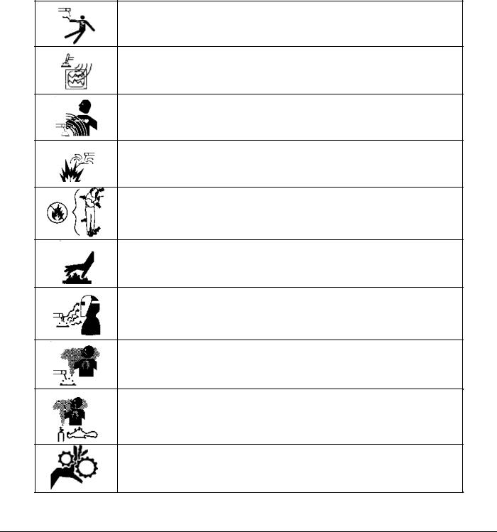
The table below contains caution and warning labels for the operation of this equipment. Before operating this or any welding equipment users should be familiar with “ANSI-49.1 Safety in Welding and Cutting”.
ELECTRIC SHOCK from welding electrode or wiring can kill.
HIGH FREQUENCY RADIO WAVE can cause interference and sometimes even damage to nearby electronic equipment (such as computers) that are un-protected.
MAGNETIC FIELDS can affect implanted medical devices. Wearers of pacemakers should keep away until consulting their doctor.
Welding can cause FIRE OR EXPLOSIONS. Do not weld near FLAMMABLE or EXPLOSIVE MATERIALS. Have proper type of extinguisher in work area.
WEAR NON-FLAMMABLE protective clothing, footwear and head gear at all times.
HOT PARTS can cause severe burns. Do not touch recently welded components. Avoid touching torch components and welding fixtures soon after welding.
ARC RAYS can burn the eyes and skin. The welding arc emits ultra-violet (UV) radiation and the molten weld gives off infrared. Both can burn eyes and skin if unprotected. Suitable eye and skin protection must be worn.
BUILD UP OF GAS can injure or kill. Weld materials can emit toxic fumes during welding. WELD ONLY IN AREAS WITH ADEQUATE VENTILATION.
FUMES AND GASES can be hazardous. Welding produces fumes and gases. Breathing these fumes and gases can be hazardous to your health. DO NOT weld in enclosed areas without proper ventilation or respirators.
MOVING PARTS - Keep hands and fingers clear from fans, gears, rotors, wire feed, rotation mechanisms.
3
M O D E L 2 1 7 W D R
O P E R A T O R ’ S M A N U A L
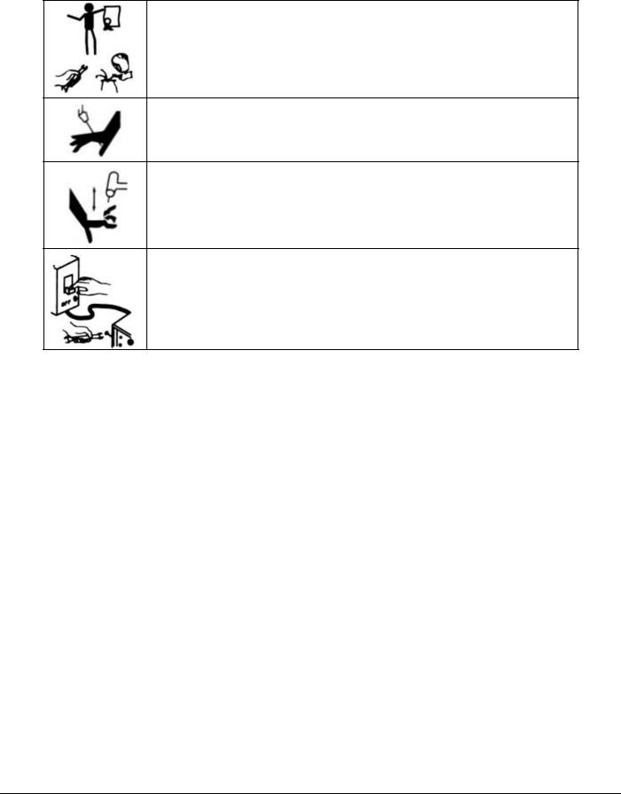
WARNING: Exel factory training is essential for all Welding
Operators and Maintenance Technicians who operate AMI or
EXEL by AMI equipment.
WELDING WIRE and ELECTRODES are sharp and can cause injury.
MOVING PARTS may cause crush or pinch points.
WARNING: Disconnect the input power to the machine before opening or servicing. Discharge all circuits that store high voltage such as capacitor packs. Only AUTHORIZED and QUALIFIED service personnel should open this equipment.
4
M O D E L 2 1 7 W D R
O P E R A T O R ’ S M A N U A L
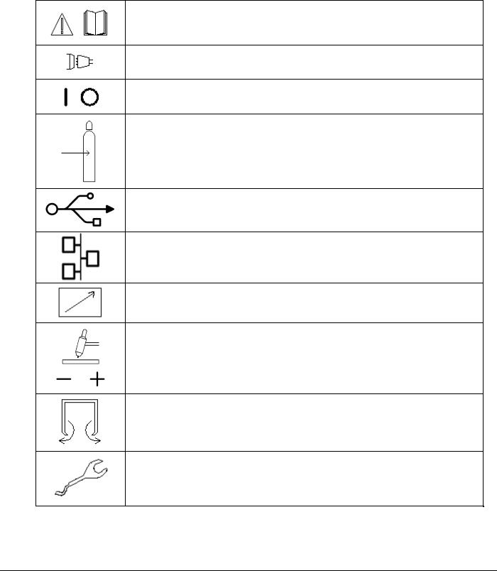
1.3 SYSTEM SYMBOLS
The following symbols are present on the Model 217 WDR:
WARNING: Read this manual! This document contains information that could help prevent injury or damage to the equipment.
AC main input, 115/230 volts AC, 50/60 Hz.
On / Off switch (CB-1 main circuit breaker).
Input for the arc shielding gas. An external regulator and flow indicator must be used.
USB port. For importing and exporting weld schedules from an external storage device. Devices should not be left plugged in while welding.
Ethernet port. For networking capability. Devices should not be left plugged in while welding.
Remote control connection.
Weld head electrode and ground connections.
Output for the arc shielding gas connection.
Weld head control. Intended for AMI and EXEL by AMI weld heads only.
5

M O D E L 2 1 7 W D R
O P E R A T O R ’ S M A N U A L
2Chapter
2.0 SPECIFICATIONS
These specifications pertain to the Model 217 WDR power supply only. For weld heads, refer to the specification sheet of each particular model. For non-AMI supplied equipment such as gas tanks and regulators, refer to the original manufacturer’s documentation. The Model 217 WDR is a mobile system that is intended to be hand carried. The supporting equipment such as weld heads, water coolers, gas regulators, remote controls and extension cables can also be hand carried. Items such as gas tanks and welding fixtures should be moved with appropriate equipment and safety precautions. Gas tanks should be securely anchored to prevent toppling over.
2.1 ELECTRICAL
INPUT POWER DETAIL
The Model 217 WDR can operate on the following Single Phase Auto Adjusting AC inputs:
Input Power |
|
Welding |
|
Rated Peak |
Amperes Input |
KVA |
|
Rated Welding |
Max OCV |
@ |
|||||
Single-Phase |
Amperage |
Starting |
At Rated Load |
||||
Output |
DC (Uo) |
Duty |
|||||
AC |
Range |
Voltage (Up) |
Output, 50/60Hz, |
||||
|
|
Cycle |
|||||
|
|
|
|
|
Single-Phase |
||
|
|
|
|
|
|
||
|
|
|
|
|
|
|
|
|
100A@11.0 |
|
59V |
|
|
|
|
115V/15A |
Volts DC, 100% |
5 – 100A |
15KV |
12A |
1.4 |
||
11-16 |
|||||||
|
Duty Cycle* |
|
|
|
|
||
|
|
|
|
|
|
||
|
|
|
|
|
|
|
|
|
150A/12.0 |
|
59V |
|
|
|
|
230V/30A |
Volts DC, 100% |
5 – 150A |
15KV |
11A |
2.4 |
||
11-16 |
|||||||
|
Duty Cycle* |
|
|
|
|
||
|
|
|
|
|
|
||
|
|
|
|
|
|
|
*DUTY CYCLE is percentage of 10 minutes that unit can weld at rated load without overheating.
Input power must be grounded.
6
M O D E L 2 1 7 W D R
O P E R A T O R ’ S M A N U A L
OUPUT POWER DETAIL
Straight polarity, constant current DC regulation intended for GTAW welding only. Static characteristic of all power supplies is flat.
5 to 100 amperes DC using 100 to120 VAC input (15 Ampere service).
5 to 150 amperes DC using 200 to 240 VAC input (30 Ampere service).
CIRCUIT BREAKER –ON/OFF, two pole, 30 Ampere at 250 VAC.
DUTY CYCLE – determined by the AC input voltage and the required output current. The Model 217 WDR system has an internal thermal sensor that will limit operation should the temperature exceed the safe operating parameters.
2.2 ELECTRICAL SERVICE GUIDE
FUNCTION |
RANGE |
|
|
INPUT VOLTAGE |
115/230 |
|
|
INPUT AMPERE AT RATED OUTPUT |
12A/11A |
|
|
MAX RECOMMENDED STD. FUSE RATING IN AMPERES |
|
CIRCUIT BREAKER, TIME DELAY |
15A |
NORMAL OPERATING |
20A |
MIN. INPUT CONDUCTOR SIZE (AWG) |
14 |
|
|
MAX. RECOMMENDED INPUT CONDUCTOR |
|
LENGTH IN FEET (METERS) |
91 (28) |
MIN. GROUNDING CONDUCTOR SIZE (AWG) |
14 |
|
|
2.3 PHYSICAL DIMENSIONS |
|
|
|
POWER SUPPLY HEIGHT |
10.5” (267mm) |
|
|
POWER SUPPLY WIDTH |
22.75” (578mm) |
|
|
POWER SUPPLY DEPTH |
18.75” (476mm) |
|
|
POWER SUPPLY WEIGHT |
70 lbs (32 kg) |
|
|
7

M O D E L 2 1 7 W D R
O P E R A T O R ’ S M A N U A L
2.4 PROGRAMMABLE AND OPERATIONAL FUNCTIONS
SINGLE ENTRY PARAMETERS AND FUNCTIONS
FUNCTION |
RANGE |
|
|
|
|
WELD TYPE (PULSED, NON-PULSED, STEP, |
SELECTABLE |
|
TACK, S^3) |
||
|
||
NUMBER OF LEVELS |
1 - 99 LEVELS |
|
|
|
|
START CURRENT |
5 - 150 AMPS |
|
|
|
|
PREPURGE |
10 - 1000 SECONDS |
|
|
|
|
POSTPURGE |
10 - 1000 SECONDS |
|
|
|
|
TRAVEL START DELAY |
0.0 - 100 SECONDS |
|
|
|
|
TRAVEL DIRECTION |
CW or CCW |
|
|
|
MULTI-LEVEL PARAMETERS AND FUNCTIONS
The following parameters and functions can be programmed in each level to change value during a weld sequence.
DOWN SLOPE |
0.0 – 99.9 SECONDS |
|
|
LEVEL TIME |
0.0 – 999.9 SECONDS |
|
|
PRIMARY (HIGH) AMPS* |
5 – 150 AMPS |
|
|
BACKGROUND (LOW) AMPS |
5 – 150 AMPS |
|
|
SLOPE TIME |
CANNOT EXCEED LEVEL TIME |
|
|
PRIMARY SPEED (RPM) |
0.0 RPM TO WELD HEAD MAX.** |
|
|
PRIMARY SURFACE SPEED (INCHES PER MINUTE) |
CALCULATED |
|
|
AVERAGE AMPS |
CALCULATED |
|
|
FREQUENCY (Hz.) |
CALCULATED |
|
|
% PRIMARY AMPS |
1% – 100% |
|
|
PRIMARY (HIGH) PULSE TIME |
0.01 – 9.99 SECONDS |
|
|
BACKGROUND (LOW) PULSE TIME |
0.01 – 99.9 SECONDS |
|
|
8

M O D E L 2 1 7 W D R
O P E R A T O R ’ S M A N U A L
MULTI-LEVEL PARAMETERS AND FUNCTIONS (con’t)
BACKGROUND SPEED (RPM) |
0.0 RPM TO WELD HEAD MAX.** |
|
|
BACKGROUND SURFACE SPEED |
CALCULATED |
|
|
AVERAGE SPEED |
CALCULATED |
|
|
*For S^3 schedules the PRIMARY AMPS parameter is replaced by START AMPS and END AMPS parameters.
**TRAVEL parameters are in 0.01 RPM increments.
9
M O D E L 2 1 7 W D R
O P E R A T O R ’ S M A N U A L
3Chapter
3.0START-UP
3.1REQUIRED PERIPHERALS
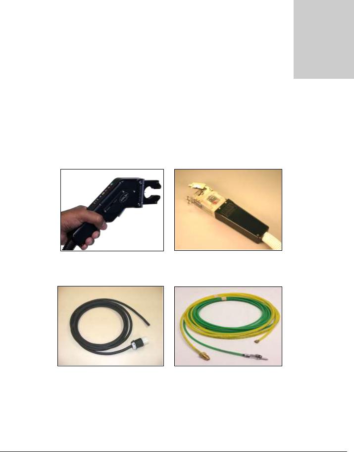
1.An orbital weld head is required to weld with the Model 217 WDR. Shown below is the EXEL by AMI RDR-05 Rotor Driver and an AMI Model 9-750 orbital weld head.
2.An A.C. power cord rated for 600 VAC service (below left) and gas purge lines are provided to connect power and inert gas to the power supply.
Note:
A.C. input power cords are shipped WITHOUT an attached utility plug. The customer must supply their own plug to connect to the main input power source.
10

M O D E L 2 1 7 W D R
O P E R A T O R ’ S M A N U A L
3.2 OPTIONAL PERIPHERALS
All AMI power supplies have their own respective optional remote pendant. This gives the operator remote welding functions of the Model 217 WDR power supply itself. The optional cooling unit is recommended for high production or heavy walled (.109”-.154”) welding applications.
Model 217 WDR Remote Pendant Model 217 WDR with optional Cooling Unit
24 inch “Cheaters” |
15 foot “Adapter” cable |
Note:
For available options such as remote pendants, water cooling units, longer adapter cables or extension cables, and more, contact Arc Machines, Inc.
11
M O D E L 2 1 7 W D R
O P E R A T O R ’ S M A N U A L
3.3 POWER SUPPLY CONNECTION
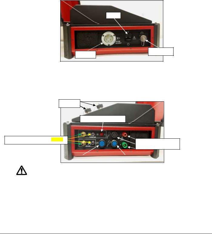
1.Below is a view of the input and output sides of the Model 217 WDR Power Supply with all connectors visible. Connect the A.C. power cord into a utility power source ranging from 115/230 volts, 50/60 hertz single phase.
CB-1
Ethernet port
Input A.C.
2.Connect Argon (or mixed gas) from an external source to the Model 217 WDR ARC GAS INPUT connector (I.D. Purge Gas optional), the ARC GAS is monitored by the computer and MUST be run through the power supply to avoid a FAULT. Connect the weld head electrode, ground, motor control, and gas line via the 24 inch cheaters or 15 foot adapter cable to the power supply.
USB ports
ID Purge-Manual ON/OFF
Arc Gas/ ID Purge Gas Inputs/Outputs
AMI/EXEL by AMI
Weld Head Connections
Remote Pendant |
|
SWAGELOK Weld Heads |
|
|
|
The Model 217 WDR is intended for typical GTAW gases ONLY. NEVER CONNECT OXYGEN OR ACETYLENE to the Model 217 WDR or weld head.
NOTE:
It is recommended to connect the Model 217 WDR to a dedicated A.C. circuit.
Power Input: 115/230 VAC, 50/60 hertz
Purge Input: 5 to 50 psi or 34 to 344 kPa.
12
 Loading...