

10500 Orbital Way
Pacoima, California 91331 U.S.A.
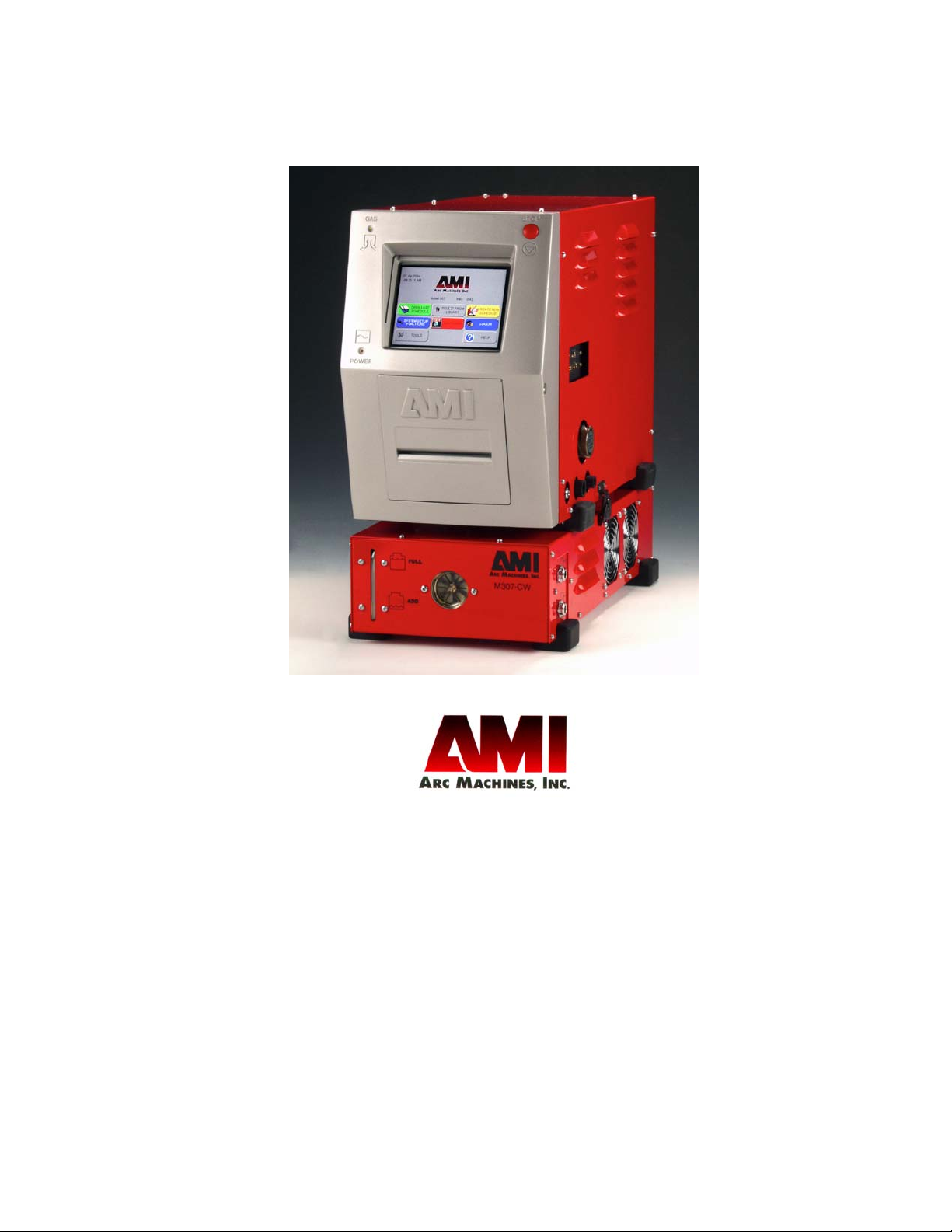
MODEL 307 POWER SUPPLY
OPERATOR TRAINING GUIDELINES
Document No. 740096
Doc. Rev. A
HEADQUARTERS
Arc Machines, Inc.
10500 Orbital Way
Pacoima, CA 91331 U.S.A.
Tel.: 1- 818 896-9556
Fax: 1-818 890-3724
sales@arcmachines.com
GERMAN OFFICE
Arc Machines GmbH
Markelsbach 2
D-53804 Much, Germany
Tel.: 02245 / 91680
Fax: 02245 / 916868
sales@arcmachines.de
EUROPEAN OFFICE
Arc Machines, Inc.
Chemin du Lavasson 2
CH-1196 Gland
Switzerland
Tel.: +41 / 22 / 995.00.51
Fax: +41 / 22/ 995.00.59
sales@arcmachines.ch
www.arcmachines.com
Document No. 740096
Rev. A
UK OFFICE
Arc Machines UK Limited
Unit 4, Raynesway Park Drive
Derby, DE21 7BH England
Tel.: 01332 / 574000
Fax: 01332 / 757757
sales@arcmachines.co.uk

MODEL 307
Operator Training Guidelines
Arc Machines, Inc.
General Guidelines for Orbital Tube and Pipe Welding
The Arc Machines Model 307 is designed to be a versatile orbital
welding control and power supply system. The Windows™-basedModel 307 features the absolute latest state-of
-the art technology,
from its 200 ampere second-generat
its color VGA display with touch screen. The Windows™ environment makes the Model 307 uniquely suited for weld logging and
weld documentation. The basic Model 307 features a complete complement of controls including gas flow and available water cooling
necessary to oper
ing tasks ranging from small diameter fusion tube welds to welding
thin-
Effective Date: September 1, 2004
Copyright 2005, Arc Machines, Inc.
wall piping with filler wire addition.
ate AMI orbital weld heads for in-place field weld-
ion solid state power supply to
Arc Machines, Inc. Model 307 Orbital Welder Training
A 5917 Correct output tolerance on pg 36 3/24/11 D.C.
Model 307 Operator Training Guidelines
Notice
This document and the information contained herein is the property of Arc
Machines, Inc. It is proprietary and submitted and received in confidence. It
shall be used only for the purpose for which it is submitted and shall not be
copied in whole or in part without the prior express written permission of Arc
Machines, Inc.
The information in this document has been carefully reviewed and is believed
to be accurate. However, no responsibility is assumed for inaccuracies.
Information and instructions in this document are subject to change and Arc
Machines, Inc. reserves the right to change specifications and data without
notice.
WARNING!
The nature of the GTAW process creates some POTENTIAL HAZARDS. In
accordance with international safety regulations the EXCLAMATION SYMBOL
indicates that this equipment is considered HAZARDOUS until an operator has
been made aware of these POTENTIAL HAZARDS by READING THIS MAN-
UAL. The LIGHTNING FLASH SYMBOL indicates that there are potential electrical hazards. The use and display of these symbols make it the OPERATOR’S
RESPONSIBILITY TO INSURE THAT HE HAS READ AND/OR BEEN MADE
AWARE OF ALL SAFETY-RELATED ITEMS CONTAINED IN THIS MANUAL.
Publication date: First Edition - September 2004
Copyright 2005 by Arc Machines, Inc.
All rights reserved.
REV DCO# CHANGE DESCRIPTION DATE APR
Document No. 740096 i.
Rev. A

Arc Machines, Inc. Model 307 Orbital Welder Training
MODEL 307 OPERATOR TRAINING GUIDELINES
EFFECTIVITY
Features and operation of the Model 307 are derived mostly from SOFTWARE.
This document is based on the latest STANDARD version of SOFTWARE at the
time of last revision (see revision page).
Some deviations in actual operation, from this document, are possible
depending on the software version of a particular machine. Please feel free to
contact Arc Machines Service Department for documentataion or information
on how software updates effect this document.
Document No. 740096 ii.
Rev. A

Table of Contents
1
INTRODUCTION
MODEL 307
OPERATOR TRAINING
GUIDELINES
2
3
4
5
6
7
8
9
10
11
SAFE OPERATION
ICONS, BUTTONS, SYMBOLS
MODEL 307 INSTALLATION
SEQUENCE OF EVENTS/
WELD PARAMETERS
POWER SUPPLY OPERATION
& FUNCTIONS
MODEL 307 LIBRARY
AUTOGENERATION OF WELD
SCHEDULES
MANUAL CREATION OF
WELD SCHEDULES
ASSOCIATED DATA
WELDING WITH THE 307
General Guidelines for
Orbital Welding of Tube
& Thin-Wall Pipe
Document No. 740096
Effective Date: September 1, 2004
Draft May 2005
12
13
14
15
16
17
18
19
20
WELD PROCEDURE
OPTIMIZATION
WELD HEAD CALIBRATION
& OPERATION
END-PREPARATION FOR
ORBITAL WELDING
TUNGSTEN
SPECIFICATIONS
PURGE GASES AND PURGE
PARAMETERS
WELD CRITERIA/WELD
QUALIFICATION
DATA ACQUISITION/
ADVANCED FUNCTIONS
APPENDICES
INDEX
Arc Machines, Inc. Model 307 Orbital Tube Welder Training
Chapter 1. Introduction to Orbital Welding with
the Model 307 Power Supply
rc Machines’
A
based Model 307 Power
Supply is designed for
autogenous orbital GTA
welding. In addition to
the standard tube-welding functions it also has
wire feed capabilities.
The Model 307 was
developed for economy
and ease of use and will
automatically generate a
weld schedule or program when the Arc
Machines weld head and
weld component dimensions are entered. To
meet the Industry’s demands for quality assurance (QA) and weld data
collection, the Model 307 has extensive capabilities to store and transmit
detailed weld documentation and historical data.
new Windows™-
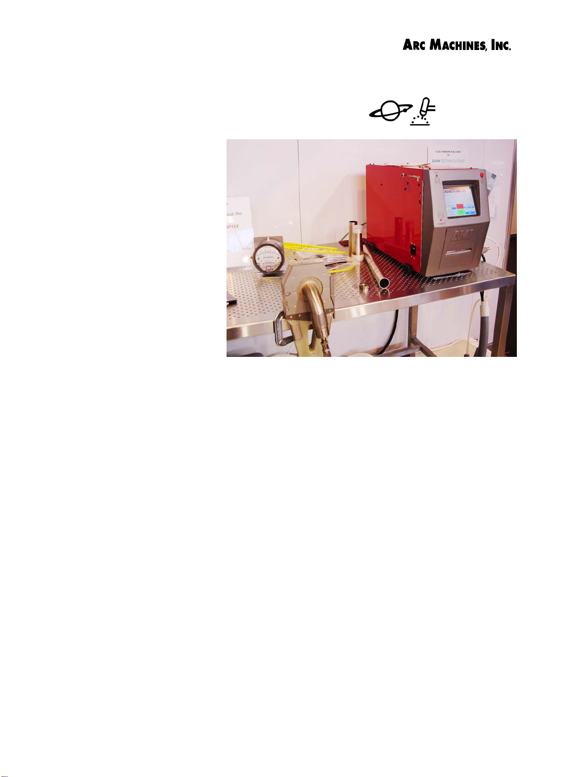
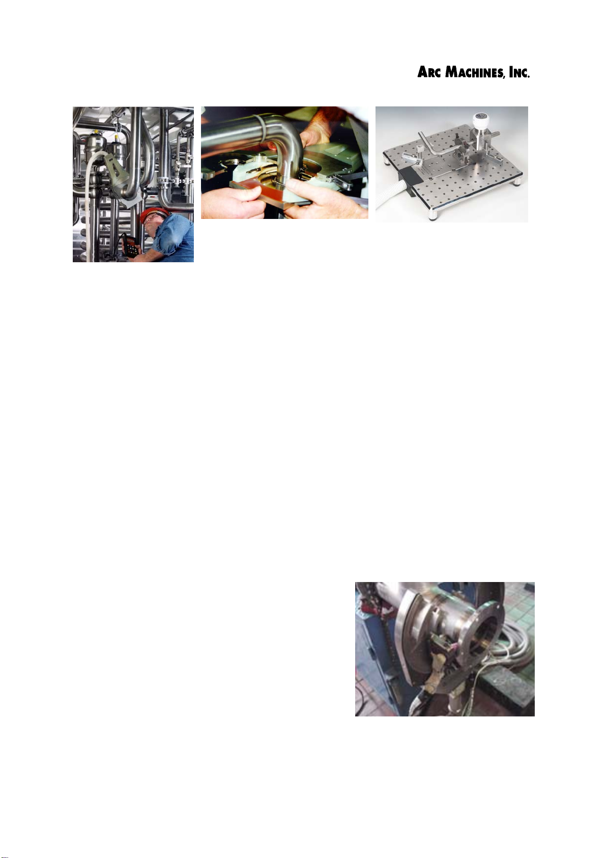
Arc Machines’ Model 307 Power Supply and Model 8-2000 weld
head on a cleanroom bench at the WELDEX show in the UK.
Welding personnel can program the Model 307 in time per level or simply
enter the desired weld head position in rotational degrees for the end of
each level, and time required to complete the level will be entered automatically. Weld parameters are clearly visible on the 307’s touch screen
and can easily be modified by the operator if changes should be necessary.
Input Power. The Model 307 Power Supply operates on 110 to 240 VAC,
50/60 Hz, single phase only, without reconnection.
Weld Current. The Model 307 has a programma
amperes of primary welding current, while av
ited to 150 amps or less. The Model 307 will warn users if programmed
current v
Weld Heads. The Model 307 operates all standard AMI fusion weld heads
includin
It can also operate the Model 95 series of wire-feed weld heads. The motor
controls can accept DC tachometer velocity feedback, or quadrature-encoder position and velocity information.
alues exceed recommendations for particular weld heads.
g the Model 8 and Model 9 series, Model 4, Model 85, and Model 96.
ble range of 5 to 200
erage current is software-lim-
Document No. 740096 Chapter 1. Page 1.
Rev. A
Arc Machines, Inc. Model 307 Orbital Tube Welder Training
Left and above: Welding in a dairy plant with a Model 8-4000 weld head.
Right: A Model 4-500 bench mount weld head.
Real-time digital data acquisition. The Model 307 captures and displays
real-time streaming data for welding current, pulsation, arc voltage and
travel speed during the weld and displays the data in graphical form on the
Model 307 screen at the end of the weld. The power supply can compare
the actual data gathered during the weld and report whether the weld
parameters were performed within pre-set acceptance limits.
Weld Logging. The Model 307’s Intel® Pentium® processor makes this
power supply uniquely suited for weld logging and weld documentation.
Weld records are created by the Model 307 when a weld identification (ID)
number is assigned to the weld. Users can select from a variety of fields of
Associated Data which include weld head and power supply serial numbers; material type and heat numbers of tubing, fittings or other weld components; gas type, flow rates to weld head and weld I.D., dewar serial
number; and electrode type and geometry.
Project management. Rapid retrieval of weld records is import
ant for
users who may be subject to audits from the FDA or other regulatory
agency. Weld records stored in the Model 307 memory can be retrieved by
project, wel
d identification number, date, welding operator, or other field.
Weld records can be downloaded onto electronic media or to a computer for compilation
of records for a particular job thus avoiding
the necessity of re-entering this data manually. Weld I.D. numbers as well as other identifying data may also be printed onto an
adhesive-backed plastic label that can be
used for weld identification purposes.
It should be understood that no welding
machine can unequivocally detect and indicate the quality of a particular weld. The
Model 307 can, however, provide a detailed
Document No. 740096 Chapter 1. Page 2.
Rev. A
Model 95-6625 Weld Head with wireFeed capabilities welding a flange to a
pipe in Guatemala. Photo courtesy of
Alimentos Maravilla S.A.

Arc Machines, Inc. Model 307 Orbital Tube Welder Training
record of each weld, so that if quality questions arise, the process of tracing the root cause of a problem is greatly simplified.
Statement of purpose: This manual is intended for use in an Arc
Machines, Inc. Model 307 Tube Welder Training class taught by a factoryapproved Arc Machines, Inc. Instructor. IT IS NOT A SUBSTITUTE FOR
THAT TRAINING. The purpose of such a class is to enable welding personnel to quickly and easily understand the basic functions and safe operation
of the Model 307 Power Supply and appropriate weld head(s) and to use this
equipment successfully in their application.
Students must be able to correctly set up the power supply and be able to
calibrate and install the weld head with correct tube-clamp inserts and the
correct tungsten type, diameter an
d length. They must understand the
basics of purging and know how to set the correct flow rates for the weld
head they are using.
Hands-On. Students are given sufficient hands-on tr
aining to enable them
to generate weld programs, to make welds, and to evaluate the welds.
Trainees should also be familiar with the end-preparation requirements for
orbital welding. They are expected to recognize an acceptable weld for
their industry or application and be able to make adjustments in the weld
program or procedures in order to produce welds that comply with the
standards of their industry.
Upon successful completion of this course, which is typically comprised of
two 8-hour days and, at the discretion of the instructor, students will
be awarded an Arc Machines, Inc. Certificate of Completion.
Document No. 740096 Chapter 1. Page 3.
Rev. A
Arc Machines, Inc. Model 307 Orbital Tube Welder Training
Chapter 2. Safe Operating Procedure -
S
afety Precautions for Model 307 Operation
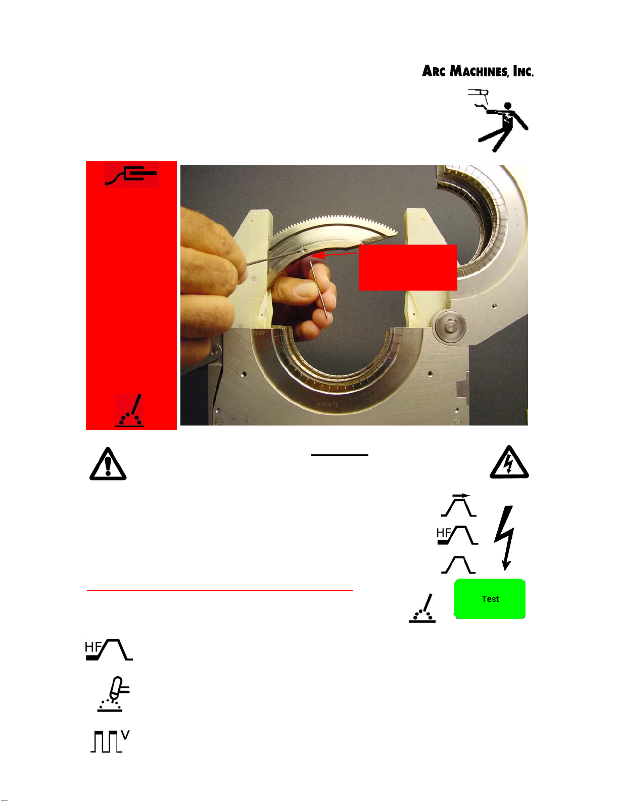
AVOID ALL
CONTACT
WITH THE
WELDING
WORK
(GROUND) OR
ELECTRODE
DURING ARC
START
Electrode installation in a Model 8
weld head.
THE ELECTRODE SHOULD ALWAYS BE
CONSIDERED A POSSIBLE SHOCK HAZARD.
This is especially true whenever the system is:
• IN SEQUENCE
• READY TO WELD,
• IS WELDING,
• OR HAS JUST FINISHED WELDING.
When replacing or adjusting the electrode:
• Set power supply to “TEST” mode
Most AMI Power Supplies feature RF (radio frequency) Arc
Starting. This is a High Voltage/High Frequency electrical transmission process. The GTAW process requires electrical potential
(high voltage) to be present on the electrode and on exposed
internal terminals during arc starting and during welding. ALL
AMI Power Supplies contain a “bleeder” circuit to ground any
residuals or potential after welding or after an aborted or bad
“arc start” attempt. However, these circuits take a few seconds
to operate or could fail.
Document No. 740096 Chapter 2. Page 1.
Rev. A
Arc Machines, Inc. Model 307 Orbital Tube Welder Training
Model 307 Do’s and Don’ts
Safe Use of Orbital Welding Equipment
DO’s
1. Do VERIFY correct AC Power Source (100 or 240 VAC
single phase) before plugging in the Model 307.
2. Do Autocal weld head (or select Manual Option)
each time the Model 307 is connected to a different
weld head. The weld head must be calibrated to the
power supply it is connected to.
3. Do CHECK ALL CABLE AND QUICK-DISCONNECT
FITTINGS
boots are in place.
to insure proper seating and that protective
4. Do check for GAS LEAKS on all external Gas fittings.
5. Do PROTECT WELD HEADS by storing in shipping
container (or otherwise suitably protected) when not in
use.
6. Do
NECTORS when not in use.
7. Do insure that the PROPER ELECTRODE is installed in
the weld head.
8. Do use a REGULATOR AND FLOWMETER designed for the
gas that is being used and suitable for the purity
requirements of the application.
KEEP PROTECTIVE COVERS ON THE MOTOR CABLE CON-
Document No. 740096 Chapter 2. Page 2.
Rev. A
Arc Machines, Inc. Model 307 Orbital Tube Welder Training
DON’TS
1. Don’t GRIND near the Weld Head or Power Supply
without protecting them.
2. Don’t use acid or other corrosives on or near the
Weld Head. A
(IPA) is the only approved liquid for cleaning of weld
heads or the Model 307.
LIGHT APPLICATION OF ISOPROPYL ALCOHOL
3. Don’t attempt to weld without a secure
WORK (GROUND) CONNECTION when using the Manual TIG
BARE METAL
Tor ch .
4. Don’t attempt to weld without PROPER FACING AND
CLEANING OF THE MATERIAL to be welded. Use only
approved cleaning products.
5. Don’t drop the Weld Head, Remote Pendant,
Cables, or Power Supply. Precautions should be taken
to secure this equipment in production situations.
6. Don’t route the cables where they will be
DAMAGE from traffic or equipment.
SUBJECT TO
7. Don’t expose the Weld Head, Remote Pendant,
Cables, or Power Supply to
ING OPERATION. Do not operate equipment when wet.
RAIN OR STANDING WATER DUR-
8. Don’t pull on cables. This will result in
DAMAGE TO THE EQUIPMENT.
Document No. 740096 Chapter 2. Page 3.
Rev. A
Arc Machines, Inc. Model 307 Orbital Tube Welder Training
Don’ts
9. Don’t attempt to move tube end into position using
the Weld Head as an alignment tool. USE PIPE STANDS,
CLAMPS, ALIGNMENT TOOLS, etc. to hold the tube or
pipe in position for welding. Tack welding of components with a weld head or a manual torch prior to
orbital welding may be necessary in some applications.
10. Don’t add oil or grease to the weld head.
11. Don’t increase GAS FLOW RATE (CFH) beyond levels
specified for each particular weld head.
12. Don’t allow TUNGSTEN OR OTHER METAL PARTICLES to
enter the gear train of the weld heads. This will cause
serious (and expensive) damage.
13. Don’t switch the Model 307 Power Supply ON and
OFF rapidly with circuit breaker (CB-1). To do so may
result in loss of stored information or resetting of system functions.
RF and EMI Emissions
Arc Machines’ policy is to comply with the IEC and FCC regulation. Every
t has been made to reduce RF emissions from our power supplies to
effor
the absolute minimum.
Document No. 740096 Chapter 2. Page 4
Rev. A
Arc Machines, Inc. Model 307 Orbital Welder Training
Model 307 Warnings
WARNINGS!
Safety Precautions
This section, concerning safe operating procedures for the
Model 307, should be read and understood before proceeding to
other sections of the training manual. It also contains precautions and warnings for the operation of welding equipment in
general. In addition, users should reference and become familiar
with “ANSI-49.1 Safety in Welding and Cutting
American National Standards Institute.
” published by the
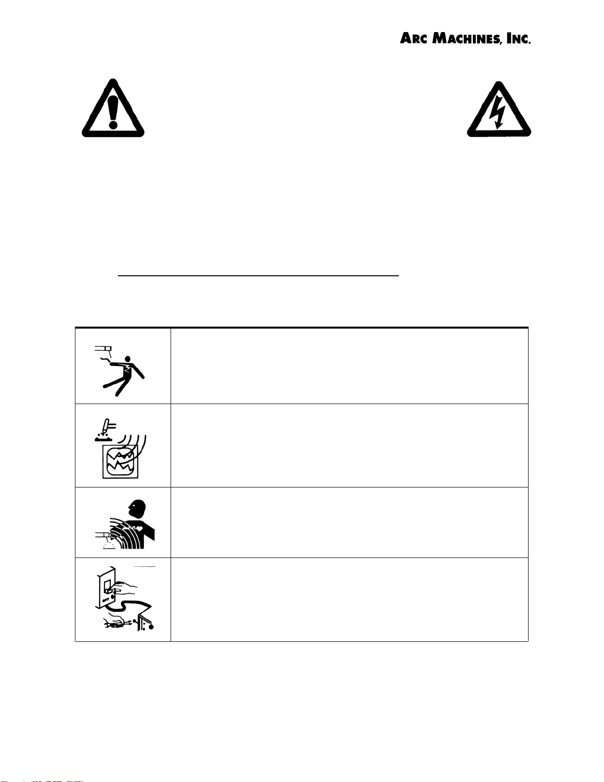
WARNING: Touching energized electrical parts can cause fatal
shocks and burns. When in weld sequence the electrode and work
are electrically energized. Incorrectly installed or improperly
grounded equipment is a hazard.
WARNING: This equipment is authorized to use a type of arc starter
that produces a High Frequency Radio Wave (sometimes called
HF or RF Starting). It can cause interference and sometimes even
damage to nearby electronic equipment (such as computers) that
are unprotected or poorly protected against such interference.
WARNING: Magnetic fields from High Currents can affect pacemakers. Pacemaker wearers should avoid being in close proximity
to welding systems.
WARNING: Disconnect the input power to the machine before
opening or servicing. Discharge all circuits that store high voltage
such as capacitor packs. Only
open this equipment.
QUALIFIED service personnel should
Document No. 740096 Chapter 2. Page 1.
Rev. A

Arc Machines, Inc. Model 307 Orbital Welder Training
MODEL 307 WARNINGS Continued:
WARNING: Welding can cause fires or explosions. Do not weld near
flammable or explosive materials. Watch for fire. Have proper type
of extinguisher in work area.
WARNING: Welding Operators should wear non-flammable protective clothing, footwear and head gear.
WARNING: Never weld on sealed containers or pipes. This may
result in an EXPLOSION.
WARNING: Welding produces high temperatures in both the
welded components and the welding equipment. Both can cause
severe burns. Do not touch recently welded components. Avoid
touching internal components of the welding system soon after use.
Avoid touching torch components and welding fixtures soon after
welding.
WARNING: The welding arc emits ultra-violet (UV) radiation and the
molten weld gives off infra-red. Both can burn eyes and skin if
unprotected. Suitable eye and skin protection must be worn.
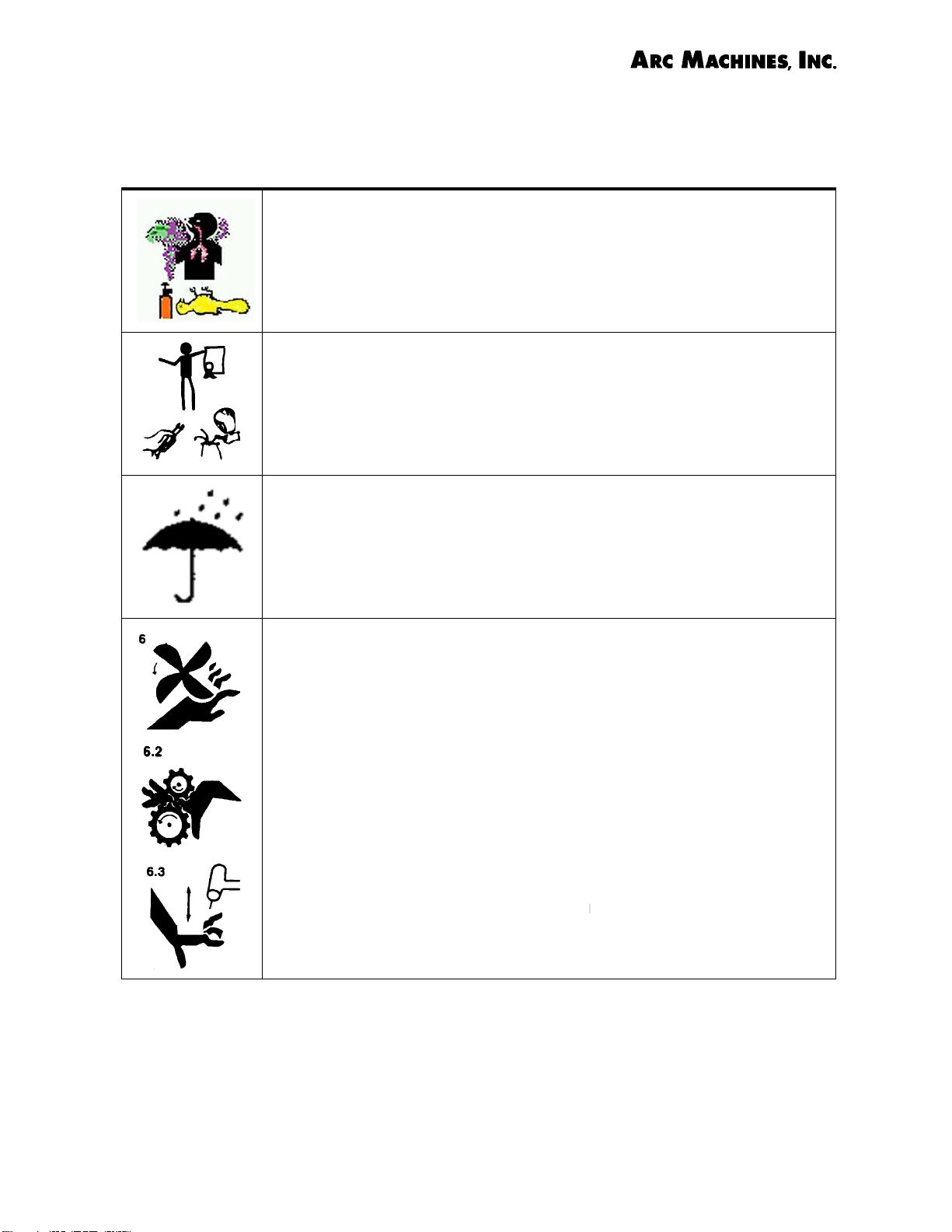
WARNING: Weld materials can emit toxic fumes during welding.
HEXAVALENT CHROMIUM, which is given off when stainless steel is
welded, causes lung cancer in humans. See Semi F79-0703
Appendix- HEXAVALENT CHROMIUM ALERT. WELD ONLY IN
AREAS WITH ADEQUATE VENTILATION.
Document No. 740096 Chapter 2. Page 2.
Rev. A
Arc Machines, Inc. Model 307 Orbital Welder Training
MODEL 307 WARNINGS Continued:
WARNING: Most GTAW gases like argon are non-toxic, however,
argon is heavier than air and will displace the normal atmosphere in
enclosed areas. DO NOT WELD IN ENCLOSED AREAS WITHOUT PROPER VENTILATION OR RESPIRATORS.
WARNING: AMI factory training is essential for all Welding Operators and Maintenance Technicians who operate AMI equipment.
Consult factory for dates of training classes and other training
information.
WARNING: Some systems, such as the M-307 Power Supply are
intended solely for indoor use and must be kept dry. Before operating, storing, or handling, always make sure that the M-307, M-307RP Pendant, weld heads and cables are not exposed to rain or
standing water. SYSTEM COMPONENTS ARE NOT WATER
PROOF.
WARNING: Keep hands and fingers clear from moving parts such
as fans, gears, rotors, and Rotation Mechanisms.
Document No. 740096 Chapter 2. Page 3.
Rev. A
Arc Machines, Inc. Model 307 Orbital Tube Welder Training
Chapter 3. Model 307 Icons, Buttons, and Symbols
Symbols and Icons have been used throughout this manual to illustrate key
points. It is hoped that this will make the manual easier to understand and to
translate for non-English-speaking people. The Windows™ operating system
uses icons as buttons that must be touched or clicked on with a mouse to
perform certain functions.
Table 1. Toolbar Icons.
Table 2. Computer buttons which appear on the touch
USER
screen and open screens or perform fu
307 are shown in Table 2.
nctions on the Model
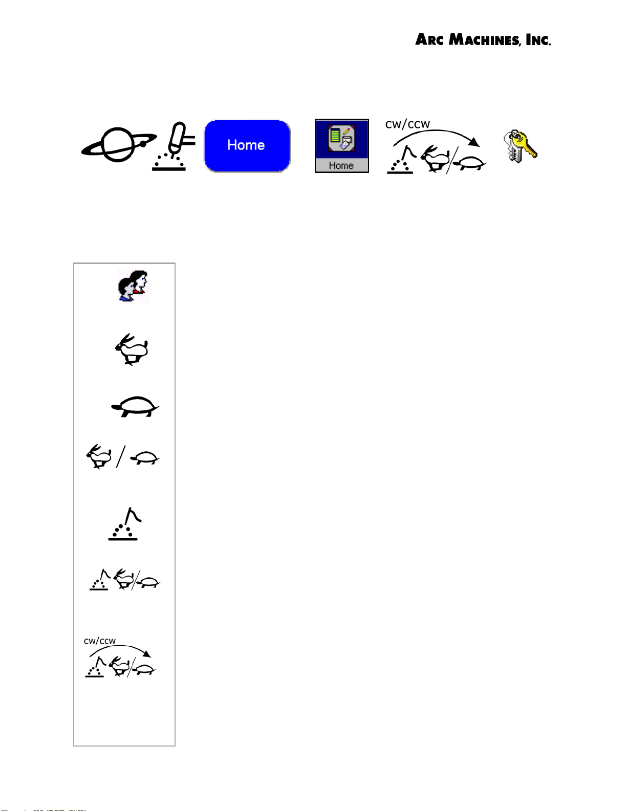
FAST
SLOW
RUN/IDLE
OR SPEED
ELECTRODE
ELECTRODE
TRAVEL SPEED
ELECTRODE
TRAVEL
DIRECTION
Table 3. Windows™- based Computer Icons used on
the Model 307 Power Supply.
Table 4. Graphic symbols used in this manual. (Symbols
related to Safety are shown in Chapter 2.) The source of the
original symbols are listed when known. When symbols
have been used in previously unpublished combinations, the
source of the original symbols are given as well as the
designation AMI to show that they have been modified in
some way by Arc Machines, Inc.
Graphic Symbols. Graphic symbols designed for use on
arc welding and cutting apparatu
(1999 revision) by the National Electric Manufacturers
Association (NEMA). While many of these symbols were
shown alone, suggestions for using them in combination to
describe combined functions were presented. In this manual
sever
ways. For example, the rabbit is the symbol for fast, while
the tortoise is the symbol for slow or idle. Together they can
mean run/ idle or speed. When combined with the symbol
for electrode, the combined symbols can be used to signify
electrode travel speed. The addition of the curved arrow,
which is the symbol for direction of rotation, creates a
symbol for the direction of electrode travel.
al of the Graphic symbols have been combined in new
s have been published
Document No. 740096 Chapter 3. Page 1.
Rev. A
Arc Machines, Inc. Model 307 Orbital Tube Welder Training
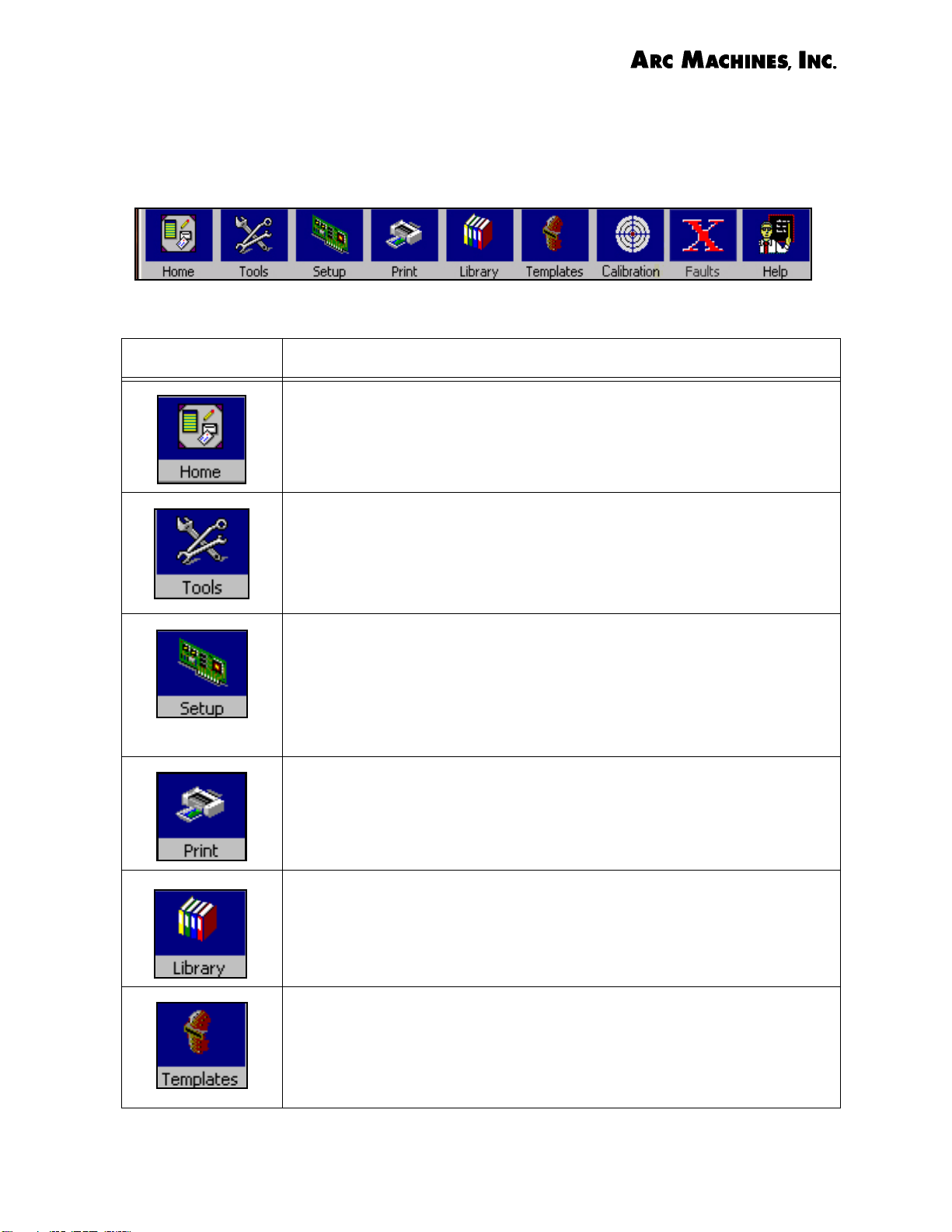
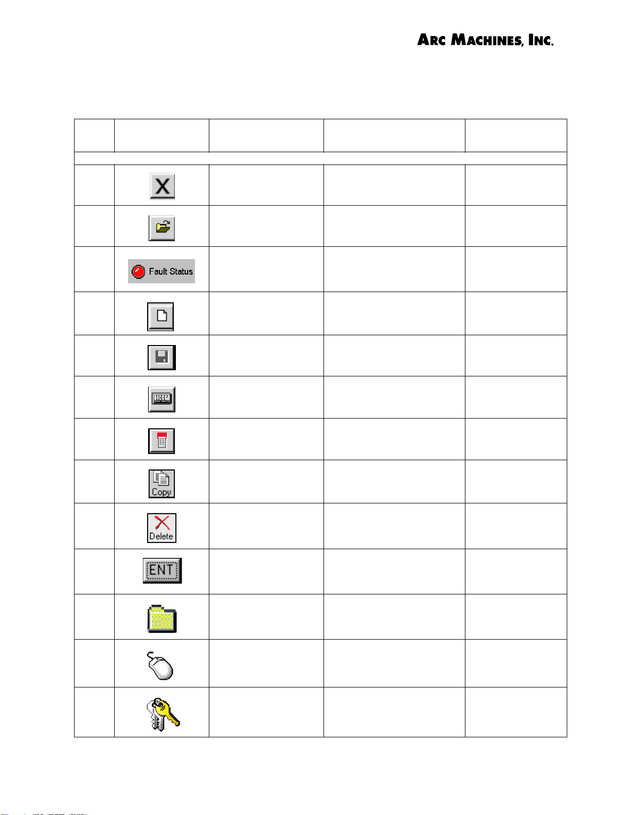
The TOOL BAR at the top of the Model 307 Touch Screen displays icons
which have a variety of functions which are listed below. When an icon is
greyed out, this means that the icon’s function is not available from that
screen.
Table I. Model 307 TOOLBAR ICONS
ICON FUNCTION
Touching the Home icon will return the user to the Model
307 Home (Opening) Screen.
Touching the Tools icon displays a menu for 307 functions for English/Metric conversions, Electrode rotation
IPM/RPM conversions, Backup Gas Pressure conversions,
a Weld Time calculator, an Electrode Calculator and a
regular Calculator.
The Setup icon displays the System Setup screen which
has functions for Backup or Transfer of weld schedules,
Security, Fault Setup, In-Sequence Display, Printer
Setup, Language, Keyboard, Weld Head Data, reset Total
Weld counter, a list of 307 screens, setting of Date or
Time, and Power Supply information.
Touching the Print icon prints a weld schedule or report
if the user is connected to a printer.
Touching the Library icon displays the list of weld programs (schedules) stored in the 307 Memory, external
data storage device, or remote M307 power supply.
Touching the Templates icon from a Weld Schedule
Screen brings up a screen with important data regarding
the weld head specified for the schedule being used.
Document No. 740096 Chapter 3. Page 2.
Rev. A
Arc Machines, Inc. Model 307 Orbital Tube Welder Training
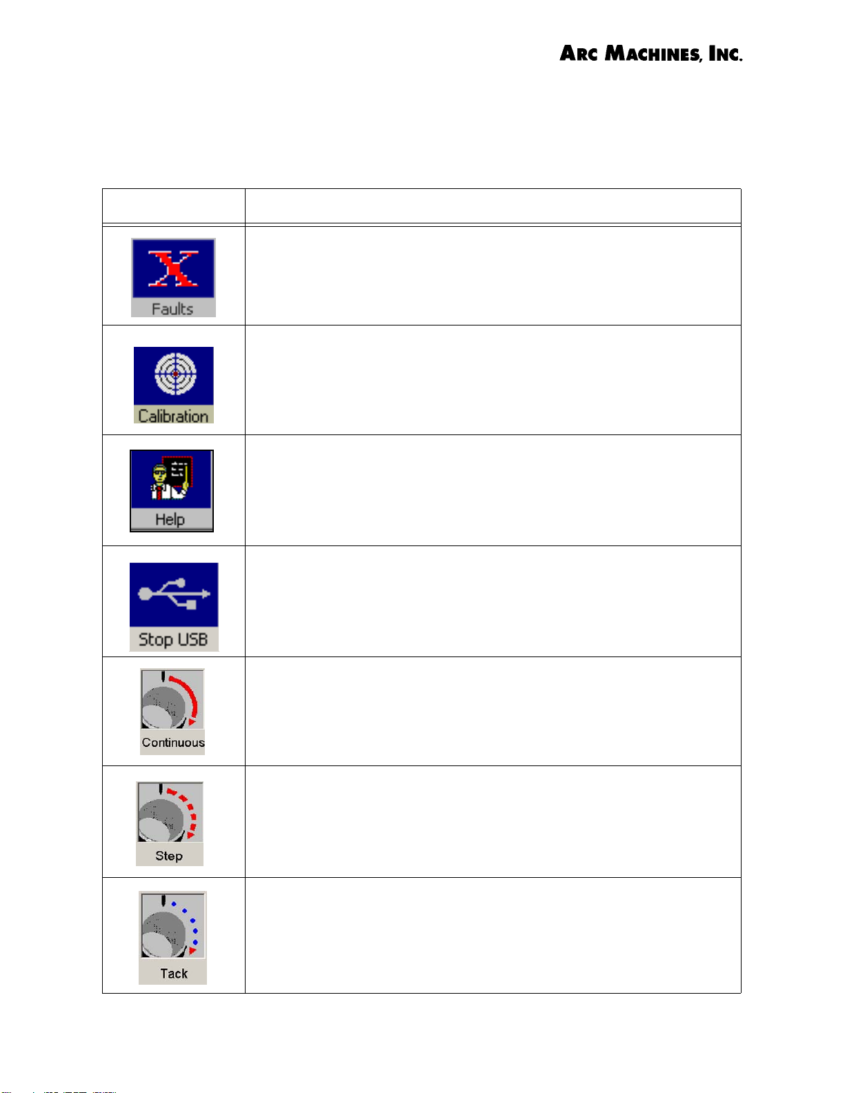
Table I. Model 307 TOOLBAR ICONS
ICON FUNCTION
Touching the Faults icon on the toolbar displays fault
settings.
Touching the Calibration icon brings up a screen with
directions for calibrating the weld head to the Model 307
Power Supply. The Icon will be greyed out if there is no
weld head connected to the power supply.
Touching the Help icon brings up the 307 Help information.
The Stop USB icon is visible from the Weld Schedule
Library screen. Press the Stop USB icon prior to removing
a USB memory stick from the Model 307 or saved files
may be lost.
Touching the Continuous Icon initiates the autogeneration of a weld schedule in which the rotation is continuous
(Primary RPM only).
Touching the Step icon initiates the autogeneration of a
weld schedule with STEP rotation mode in which the electrode moves only during the background current pulse.
Touching the Tack icon initiates the autogeneration of a
weld schedule for making orbital tack welds.
Document No. 740096 Chapter 3. Page 3.
Rev. A
Arc Machines, Inc. Model 307 Orbital Tube Welder Training
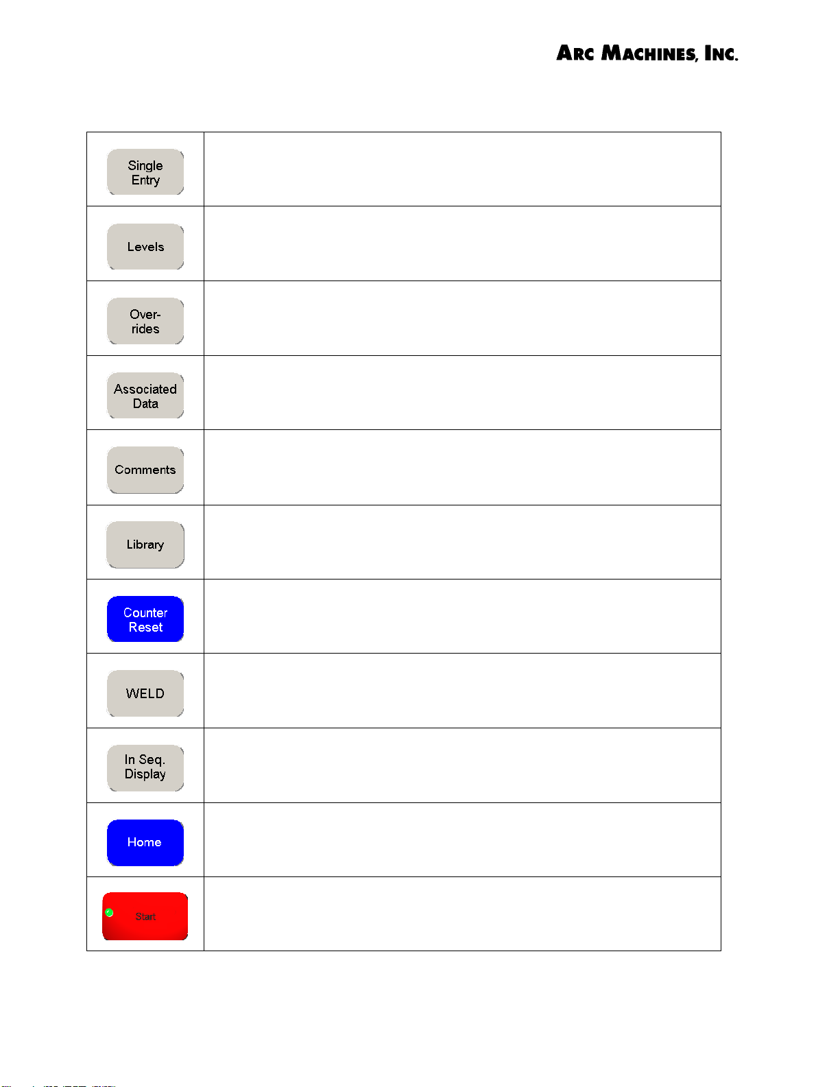
Table 2. Buttons used on the Model 307 Power Supply
Pressing Single Entry displays the Weld Schedule - Single Entry
screen on which weld parameters which apply to all levels of a weld
program are entered.
Pressing the Levels button displays the Weld Schedule - Weld Levels
screen on which weld parameters that can be changed for each level,
such as amperages and pulse times, are entered.
Pressing Overrides opens the Weld Schedule - Overrides screen on
which upper and lower limits for weld schedule parameters may be set.
Pressing Associated Data opens the Associated Data Main Screen
from which other screens are accessible for entering data on Tube,
Equipment, Gas, Electrodes and Comments.
Pressing Comments opens the Associated Data Comments screen
which is a blank screen for writing comments about a particular weld
schedule.
Pressing Library opens the Model 307 Weld Schedule Library in
which weld schedules stored in the Model 307 Library are listed and may
be opened for welding.
Pressing Counter Reset opens the Counter/Alert Indicator screen.
From this screen you may enable, disable, or reset the alert indicator
and weld counter.
Pressing Weld opens the Weld Schedule Weld Screen from which the
weld sequence (welding) can be initiated when in Weld Mode.
Pressing In Seq. Display opens the In-Sequence Display Selection
Screen which allows the user to select data for display during the weld
sequence.
Pressing Home returns the user to the Model 307 Opening Screen (1).
Pressing the Start button in Weld Mode initiates the Weld Sequence.
Pressing Start from Test Mode initiates a weld sequence in which an arc
is not struck.
Document No. 740096 Chapter 3. Page 4
Rev. A

Arc Machines, Inc. Model 307 Orbital Tube Welder Training
Table 2. Buttons used on the Model 307 Power Supply
Pressing the Test button on the Weld Schedule Weld Screen puts the
Model 307 into Weld Mode.
Pressing the red WELD button on the Weld Schedule Weld screen puts
the Model 307 into Test Mode.
Touching the Data Acquistion button opens the Weld Identification
Information screen. Weld Data Recording may be enabled or disabled
from this screen.
Touching the Weld Main button opens the Weld Schedule Main screen
of the open weld schedule.
Library Buttons
Create Folder opens a screen on which the name of the new folder is
entered. This folder may be used for storing a user-defined group of
weld schedules.
Rename Folder opens a screen on which the name of a specified folder
appears. A new name may be assigned to the folder.
Delete Folder opens a screen asking whether the user truly wants to
delete the selected folder. To delete the folder touch YES. To cancel
choose NO.
Paste Folder will paste a folder that has been copied into the selected
Library.
Copy Folder copies the selected folder which may then be pasted into a
remote machine.
Open Schedule. When a weld schedule is selected in the Library, this
button will open the schedule to the Main Weld Schedule Screen.
Copy Schedule copies the selected schedule so that it may be pasted
into another folder or to the Library of a remote machine.
Delete Schedule will ask the user if he truly wishes to delete a selected
schedule. When the user touches YES, the schedule will be deleted.
Document No. 740096 Chapter 3. Page 5
Rev. A
Arc Machines, Inc. Model 307 Orbital Tube Welder Training
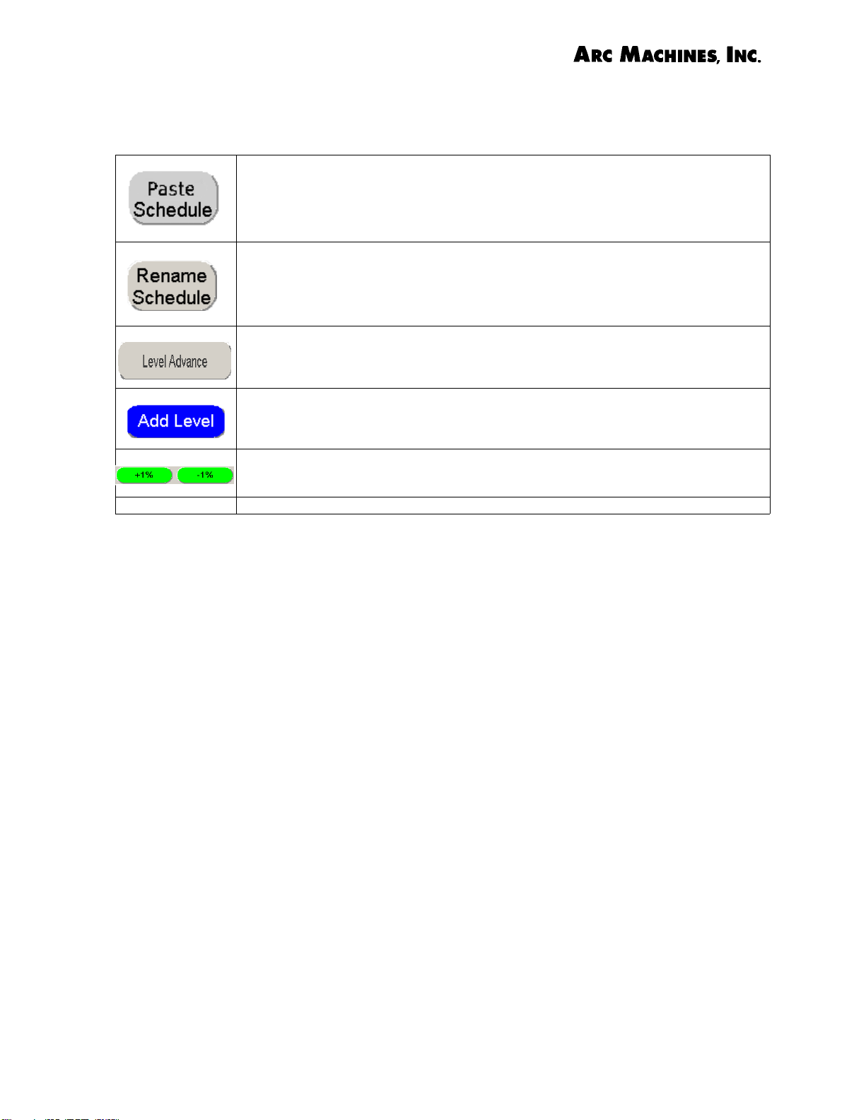
Table 2. Buttons used on the Model 307 Power Supply
Paste Schedule inserts a copied schedule into another folder of the
same power supply or into a folder in a Library in remote power supply.
Rename Schedule allows the user to change the name of a selected
schedule by typing in the new name from the keyboard.
Level Advance. Touching the Level Advance button on the touch screen
or on the remote pendant during the weld sequence advances the
program to the next level.
Add Level. When the Levels screen of a weld schedule is visible additional Levels may be added to the schedule by touching this button.
Plus or Minus 1%. Both Primary and Background Amps of a weld
schedule are changed 1% up or down by touching one of these buttons.
Document No. 740096 Chapter 3. Page 6
Rev. A
Arc Machines, Inc. Model 307 Orbital Tube Welder Training
Table 3. Computer Icons used on Model 307
NO. Symbol
1
2
3
4
5
6
Function, Keyword or Phrase
Close - At upper
right of screen
Open To S i gn i fy O pen i ng o f a
Fault Status
Indicator - Red or
Green
New To S ign i fy C rea tin g a
Save To Signify Saving a File Microsoft
Keyboard To Signify a Computer
Application Source
To S i gn i fy C los i ng o f a
Computer file
Computer File
Red Si
Condition - Green is OK
New File
Keyboard
gnifies a 307 Fault
Microsoft
Microsoft
AMI
Microsoft
Microsoft
7
8
9
10
11
12
13
307 RP Symbol To Signify the 307
Remote Pendant
Copy To Signify Copying or
Duplicating a File
Delete To Signify Deleting a File Microsoft
ENT Button used to Signify
the Enter Key on a Keyboard
Folder To Signify File Folder for
Weld Schedules
Mouse To S ign ify u se o f a
Mouse, Mouse Click, or
Software
Password To S ign i fy u se o f a
Password to Access a
Program or Syste
m
AMI
Microsoft
Microsoft
Microsoft
AMI
Microsoft
Microsoft
Document No. 740096 Chapter 3. Page 7
Rev. A
Arc Machines, Inc. Model 307 Orbital Tube Welder Training
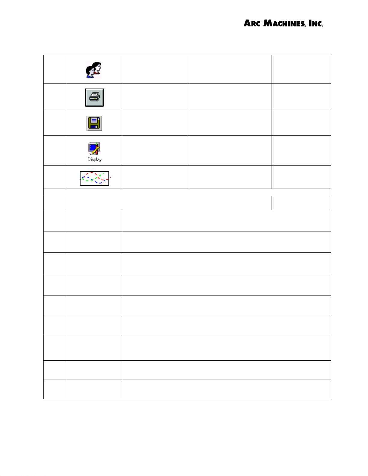
Table 3. Computer Icons used on Model 307
14
15
16
17
18
1 Touch
Screen
Users To S i gn i fy U ser s (o r
Classification of User
such as Supervisor, etc.)
Printer To Signify a Printer or to
Print a File
Floppy disk To Signify a File or Data
such as a Weld
Record(s)
Display To Signify a Computer
Monitor Screen
Streaming Data To S i gn i fy Re al T ime
Digital Data Output
Windows® Functions and Definitions
A Computer Screen that Accepts Commands by Touch
Microsoft
Microsoft
Microsoft/AMI
Microsoft
AMI
2 Too lb ar
3 Pull-Down
Menu
4 Left or Right
Click
5 Double Click
6 Check Boxes
Scroll Bar
Drag
Drop
Windows® places toolbars across the tops of programs with buttons for various tasks such as copy, cut, paste, etc.
A list of options that appears when choosing a selection from the
Menu Bar or other feature.
To push and release the right or left button on the mouse. These
have separate functions.
To push and release the left mouse button twice in rapid succession.
Clicking in a box next to an option places a check in the box and
changes its setting.
Box at right hand side of screen that when moved vertically up or
down moves the viewing window up or down. A similar scroll bar at
the bottom of the screen moves the view from side to side.
A four-step process that moves an object across your desktop.
First touch the object and drag the object to the new location.
(Used after Drag) Letting go of the mouse (or releasing your finger) allows the object to remain at the new location.
Document No. 740096 Chapter 3. Page 8
Rev. A
Arc Machines, Inc. Model 307 Orbital Tube Welder Training
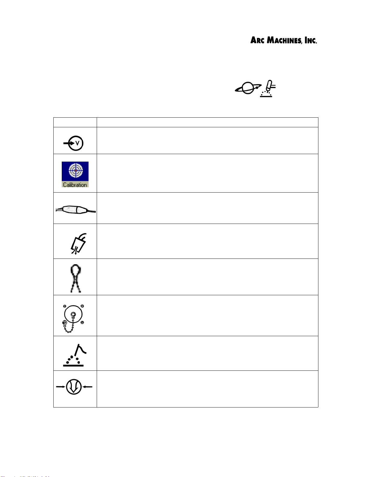
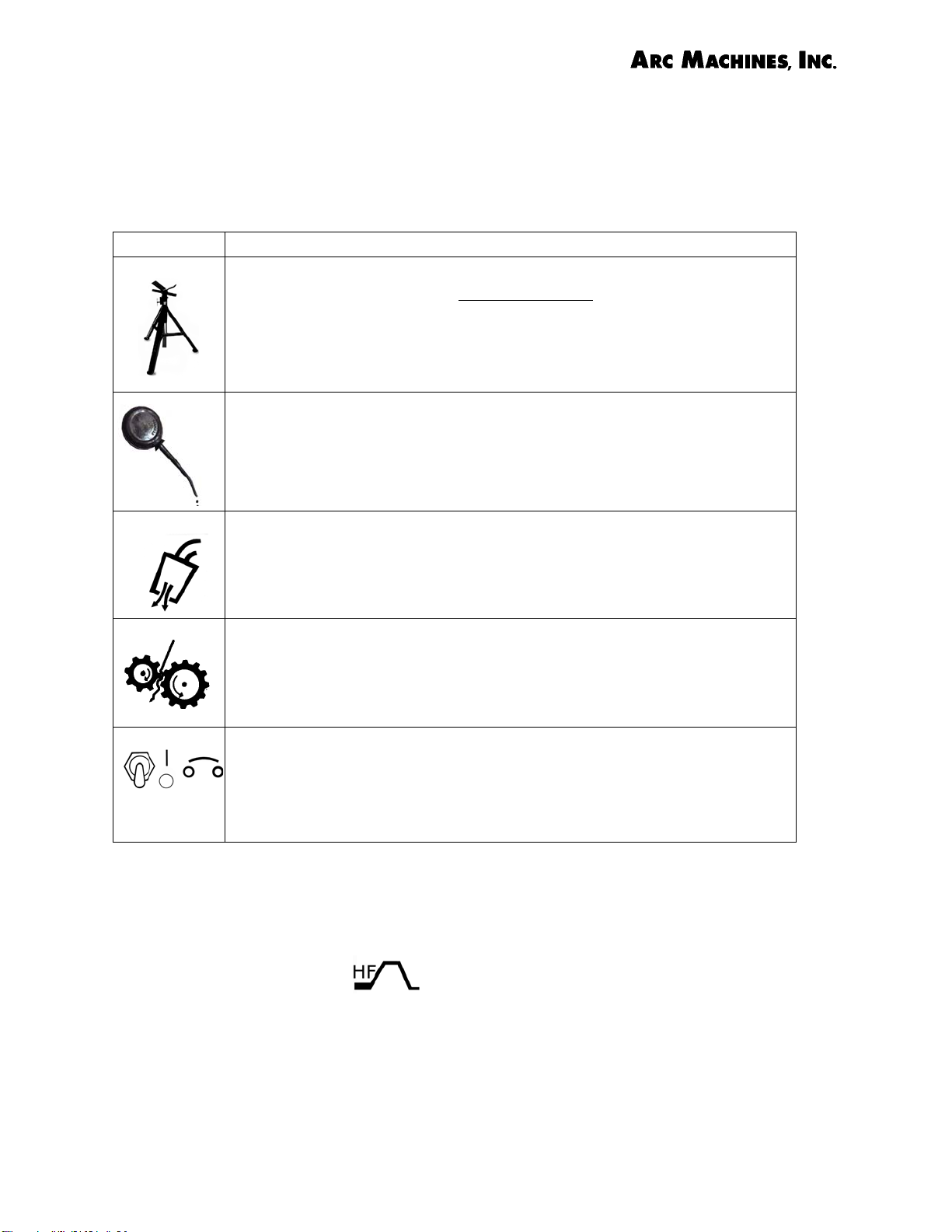
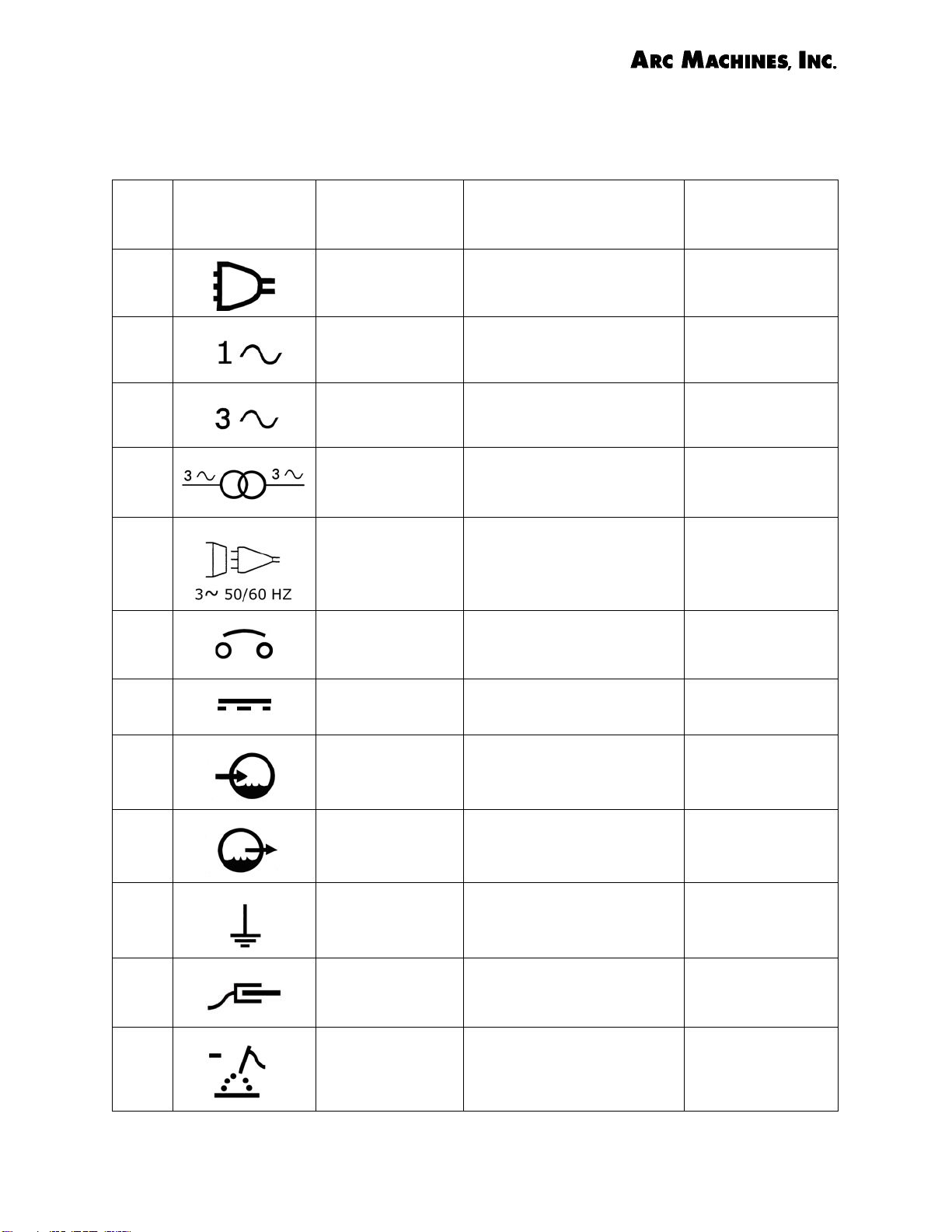
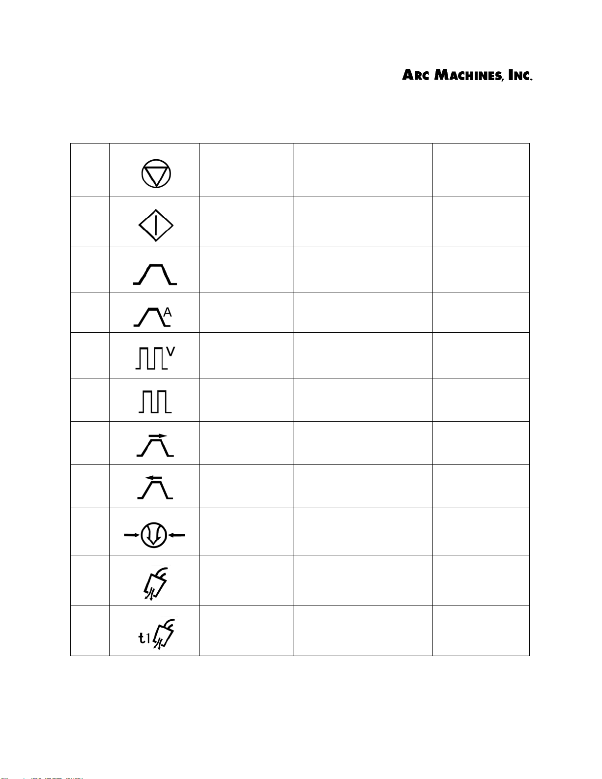
Table 4. Graphical Symbols used in this Manual
NO. Symbol
1
2
3
4
5
6
Function, Keyword or
Phrase
Line To Signify a Power Line or
Single Phase To Signify Single Phase IEC 974
Three Phase To Signify Three Phase IEC 974
Three Phase
Trans f orme r
Line Connection
(Three Phase at
50 to 60 Hertz)
Circuit Breaker To S ign i fy a Ci r cui t
Application Source
ANSI/NEMA
Cord
Signifies Three Phase
Trans f orme r
gn i fy a Li n e Co nne c-
To S i
tion
Breaker in an Electrical
Circuit
IEC
974
IEC 974
ANSI/NEMA
7
8
9
10
11
12
Direct Current
(DC)
Water
Coolant Input
Water Coolant
Output
Earth (Ground) To S ign i fy t he E art h
Work Connection
Electrode Negative
Signifies Direct Current IEC 417
To S i gn i fy Wa t er
(Coolant) Input
To S i gn i fy Wa t er
(Coolant) Output
(Ground) Connection
To Signify a Work Piece
Connection
To S i gn i fy E lec t ro d e N e gative Connection or
Switch P
osition
5031
ANSI/NEMA
ANSI/NEMA
IEC 417
5017
ISO 7000-0453
ANSI/NEMA
Document No. 740096 Chapter 3. Page 9
Rev. A

Arc Machines, Inc. Model 307 Orbital Tube Welder Training
Table 4. Graphical Symbols used in this Manual
13
14
15
16
17
18
Electrode To S ign ify a n E l ect rod e ANSI/NEMA
Electrode
generic
Gas Type To Signify the Type of
Gas Supply To Signify a Gas Supply ANSI/NEMA
Gas Input To Signify Gas Input ANSI/NEMA
Ventilating and
Air Circulating
Fan
Signifies a generic electrode
Gas Such As Argon, CO
To Signify a Ventilating
Fan or Air Circulating
ANSI/NEMA
ANSI/NEMA
2
ISO 7000-0089
19
20
21
Document No. 740096 Chapter 3. Page 10
Rev. A
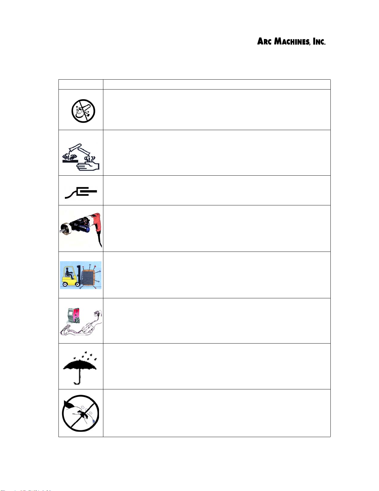
Grinder To Signify not to grind in
certain areas - contamination caused by grinding
Protective Boots
over Cable
Connector
Exclamation
Point
To Signify Secure Connection with Protective
Boots
To Signify Warning, Danger, Caution
AMI
AMI
IEC 417
5036A
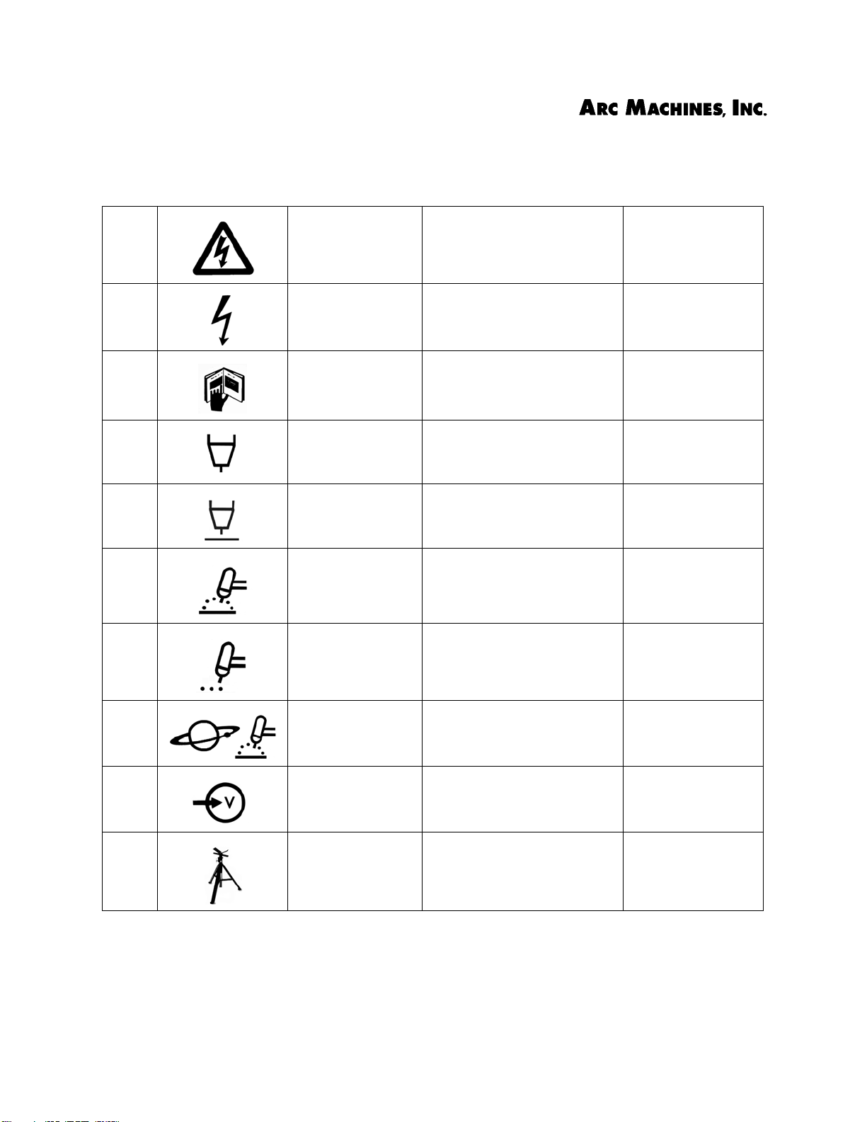
Arc Machines, Inc. Model 307 Orbital Tube Welder Training
Table 4. Graphical Symbols used in this Manual
22
23
24
25
26
27
Lightning Symbol for Severe Elec-
trical Shock Hazard
Dangerous Voltage
Read Operator’s Manual
Tor c h Signifies a Welding or
Arc Gap or Arc
Voltage Control
(AVC)
Gas Tungsten
Arc Welding
(GTAW) Torch
To S i gn i fy D ang e ro u s
Voltage
To Signify that the Operator’s Manual Should be
Read
Cutting Torch
Signifies Arc Gap or Arc
Voltage Control (AVC)
To S ign i fy a GTA W Tor c h ISO 7000-0465
IEC 417
5036A
IEC 417
5036A
SAE
ANSI/NEMA
ANSI/NEMA
AMI
28
29
30
V
31
Document No. 740096 Chapter 3. Page 11
Rev.A
Ta c k We ld i ng
(GTAW)
Orbital GTAW To Signify the Orbital
Input Voltage/
Power
Pipestand To S ig n ify use o f a
To Signify Tack Welds
with a GTAW Torch
GTAW Process
To Signify Input Voltage
(Power)
Pipestand
ISO 7000-0465
ISO 7000-0465
AMI
IEC 417
5034
ANSI/NEMA
AMI
Arc Machines, Inc. Model 307 Orbital Tube Welder Training
Table 4. Graphical Symbols used in this Manual
32
33
34
35
36
37
38
Stop of Action To Signify the Stop (of
Action) Function or Control
Start To Signify the Start (of
Action) Function or Control
Process Cycle To Signify One Complete
Process Cycle
(Weld Sequence)
Weld Current To Signify Welding Amps
During Process Cycle
Arc Volts To Signify Arc Volts Dur-
ing Process Cycle
Pulse Signifies Pulse Function
or Control
Sequence
Advance
To Signify Advancing to
the Next Sequence Event
(Level)
ANSI/NEMA
ANSI/NEMA
ANSI/NEMA
ANSI/NEMA
ANSI/NEMA
ANSI/NEMA
ANSI/NEMA
39
40
41
42
Document No. 740096 Chapter 3. Page 12
Rev. A
Sequence
Deadvance
Air (Gas) Pressure
Purge by Gas To Signify Purging of Air
Gas Preflow To Signify Gas Preflow
To Signify Returning to
the Previous Sequence
Event (Level)
To Signify Air (or Gas)
Pressure Function or Control
(by Gas)
Time (PREPURGE)
ANSI/NEMA
ANSI/NEMA
ISO
7000-0474
ISO 7000-0474
ANSI/NEMA
Arc Machines, Inc. Model 307 Orbital Tube Welder Training
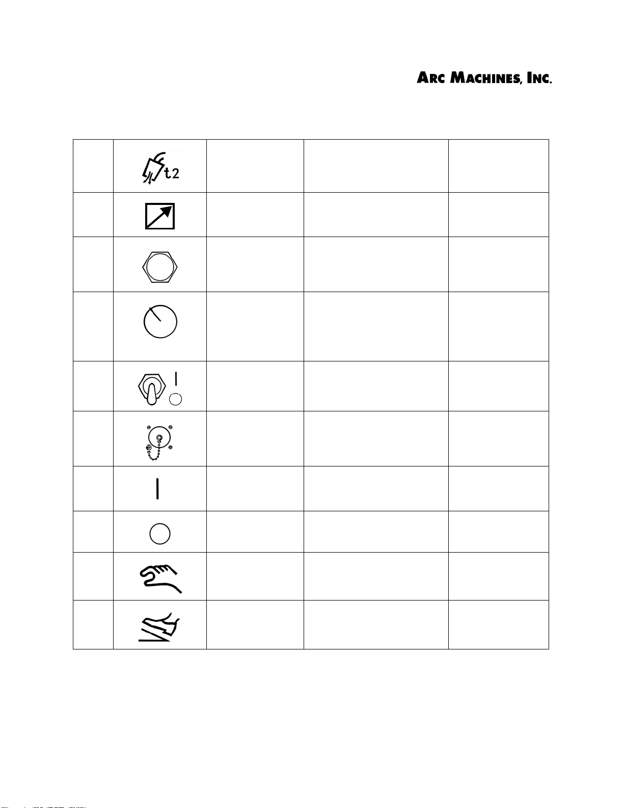
Table 4. Graphical Symbols used in this Manual
43
44
45
46
47
48
Gas Postflow To Signify Gas Postflow
(POSTPURGE) Flow
Remote Signifies Remote Opera-
tion or Control
Pushbutton To Signify a Pushbutton
Switch used to Start or
Stop a Function
Panel/LOCAL To Signify Panel/Local
Function or Switch such
as a Switch to Change
Between a Local Control
and a Remote Control
ON-OFF Switch To S ign i fy a n ON -OF F
Switch
Receptacle To Signify a Receptacle
Type Connector
ISO 7000-0474
ANSI/NEMA
ANSI/NEMA
ANSI/NEMA
ANSI/NEMA
ANSI/NEMA
ANSI/NEMA
49
50
51
52
Document No. 740096 Chapter 3. Page 13
Rev. A
ON
(Enable)
OFF
(Disable)
Hand To S i gn i fy M anu al
Foot Control To Signify a Foot Control
To Signify the ON or
Enabled State of a
Function
To Signify the OFF or Disabled State of a Function
Control of a Function or
Tool
Device, Function, Connection or Control
ANSI/NEMA
ANSI/NEMA
ANSI/NEMA
ANSI/NEMA
Arc Machines, Inc. Model 307 Orbital Tube Welder Training
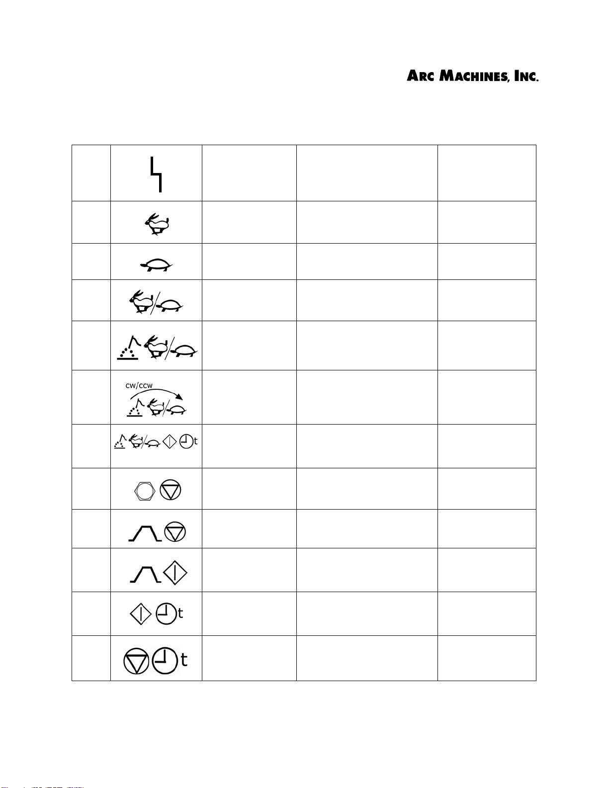
Table 4. Graphical Symbols used in this Manual
53
54
55
56
57
58
59
Disturbance (or
change)
Fast To Signify Fast Action or
Slow To Signify Slow Action or
Travel Speed To S ign ify Trav e l or Run
Electrode Travel
Speed
Direction of
electrode travel
Electrode Travel
Start Delay
To S ign i fy a Di s tur ban ce
in the Proper Run of a
Procedure, or Fault Condition
Operation
Operation
Speed
To Signify Travel Speed
of the Electrode or Torch
To S ign i fy D ire cti o n o f
Electrode Travel
To Signify the Time after
Arc Start that the Electrode Begins to Move
ISO 7000-0228
SAE
SAE
SAE
SAE
ANSI/NEMA
AMI
ANSI/NEMA
/AMI
ANSI/NEMA
/AMI
60
61
62
63
64
Document No. 740096 Chapter 3. Page 14
Rev.A
ALL STOP To S ign i fy s hut dow n of
Power Supply
Sequence STOP To Signify stopping of the
weld sequence
START
Sequence
Start Delay
Time
Stop Delay Time To Signify a Timed Delay
To Signify initiation of
weld sequence
To Signify a Timed Delay
in Starting a Function
in Stopping a Function
ANSI/NEMA
AMI
ANSI/NEMA
AMI
ANSI/NEMA
AMI
ANSI/NEMA
AMI
ANSI/NEMA
AMI
 Loading...