

Model 217 WDR Tube Welding Power Supply
Part No. 740126
Revision A
Operator’s Manual

M O D E L 2 1 7 W D R
Change Description
A
1190150
Initial release
T
O P E R A T O R ’ S M A N U A L
INTRODUCTION
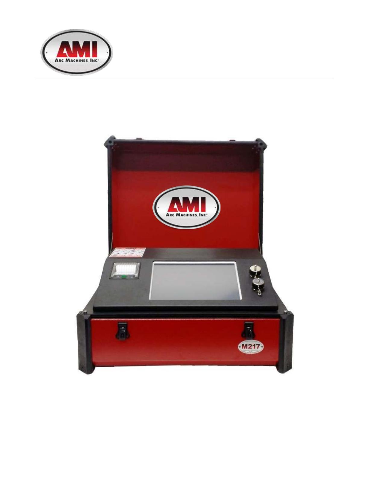
he Model 217 WDR is a power source and controller for automatic orbital tube
welding. It is intended to be used only in conjunction with AMI and EXEL by AMI
orbital tube welding heads and accessories. The Model 217 WDR power supply
provides GTAW (Gas Tungsten Arc Welding) current with pulsation controls, high
frequency arc starting, purge gas controls, weld head arc rotation and automatic timing
functions. Users need only to supply input A.C. power, a regulated inert gas source with flow
meter, and the appropriate weld head or accessories.
NOTICE
This document and the information contained herein is the property of Arc Machines,
Inc. It is proprietary and submitted and received in confidence. It shall be used only for
the purpose for which it is submitted and shall not be copied in whole or in part without
the prior expressed written permission of Arc Machines, Inc. The information in this
document has been carefully reviewed and is believed to be accurate. However, no
responsibility is assumed for inaccuracies. Information and instructions in this document
are subject to change and Arc Machines, Inc. reserves the right to change specifications
and data without notice.
Revision History
i

M O D E L 2 1 7 W D R
O P E R A T O R ’ S M A N U A L
Table of Contents
INTRODUCTION, NOTICE, Revision History ................................................................ i
Table of Contents .......................................................................................................... ii
1.0 SAFETY PRECAUTIONS .................................................................................. 1
1.1 SHOCK HAZARD WARNING ............................................................................ 1
1.2 WARNING LABEL DEFINITIONS .................................................................... .3
1.3 SYSTEM SYMBOLS .......................................................................................... 5
2.0 SPECIFICATIONS ............................................................................................. 6
2.1 ELECTRICAL .................................................................................................... 6
2.2 ELECTRICAL SERVICE GUIDE ....................................................................... 7
2.3 PHYSICAL DIMENSIONS ................................................................................. 7
2.4 PROGRAMMABLE AND OPERATIONAL FUNCTIONS .................................. 8
3.0 START UP ....................................................................................................... 10
3.1 REQUIRED PERIFERALS ............................................................................... 10
3.2 OPTIONAL PERIFERALS ............................................................................... 11
3.3 POWER SUPPLY CONNECTION ................................................................... 12
3.4 POWER UP ...................................................................................................... 13
4.0 LIBRARY AND MEMORY ............................................................................... 14
4.1 LOADING A WELD SCHEDULE FROM THE MODEL 217 WDR LIBRARY . 15
4.2 COPYING WELD SCHEDULES FROM THE MODEL 217 WDR TO AN
EXTERNAL MEMORY DEVICE ...................................................................... 18
4.3 COPYING WELD SCHEDULES FROM AN EXTERNAL MEMORY DEVICE
TO THE MODEL 217 WDR LIBRARY ............................................................. 21
5.0 CREATING WELD SCHEDULES .................................................................... 24
5.1 CREATING A MANUAL 4 LEVEL WELD SCHEDULE ................................... 24
5.2 CREATING AN AUTO 4 LEVEL WELD SCHEDULE ..................................... 27
5.3 CREATING AN AUTO STEP WELD SCHEDULE ........................................... 29
5.4 CREATING AN AUTO TACK WELD SCHEDULE .......................................... 31
5.5 CREATING AN AUTO S^3 WELD SCHEDULE ............................................. 33
6.0 SETUP ............................................................................................................. 36
6.1 PROGRAM BASIC SETUP FEATURES ......................................................... 36
6.2 PROGRAM THE LANGUAGE FEATURES ..................................................... 37
6.3 PROGRAM THE PASSWORD FEATURES .................................................... 38
7.0 ALARMS AND FAULTS .................................................................................. 39
7.1 PROGRAMMING ALARM SETTINGS ............................................................ 39
7.2 ALARM SETTINGS ......................................................................................... 41
7.3 ALARMS AND FAULTS .................................................................................. 41
7.4 PRINTING ........................................................................................................ 42
7.5 PROPER SHUTDOWN OF THE MODEL 217 WDR ....................................... 43
ii

M O D E L 2 1 7 W D R
O P E R A T O R ’ S M A N U A L
8.0 MAINTENANCE AND TROUBLESHOOTING ................................................. 44
8.1 GENERAL MAINTENANCE ............................................................................ 44
8.2 TROUBLESHOOTING ..................................................................................... 45
AMI OFFICES .................................................................................................. 47
iii
M O D E L 2 1 7
Electrical
Hazard
Chapter
1
I C O N K E Y
Warning
O P E R A T O R ’ S M A N U A L
1.0 SAFETY PRECAUTIONS
The Model 217 WDR is intended to be used only with AMI or EXEL by AMI weld heads for
the purpose of GTAW welding of metal tube. The system is not to be used for any other
purpose, specifically heating or cutting.
1.1 SHOCK HAZARD WARNING
WARNING
The nature of the GTAW process creates POTENTIAL HAZARDS. In accordance with
international safety regulations the EXCLAMATION SYMBOL indicates that this
equipment is considered HAZARDOUS. The LIGHTNING FLASH SYMBOL indicates that
there are potential electrical hazards. The use and display of these symbols make it the
OPERATOR’S RESPONSIBILITY TO ENSURE THAT HE HAS READ AND/OR BEEN
MADE AWARE OF ALL OF THE SAFETY-RELATED ITEMS CONTAINED IN THIS
MANUAL.
HIGH VOLTAGE is present on exposed terminals. The ELECTRODE (tungsten/rotor) is
also an EXPOSED TERMINAL and by its nature the GTAW process requires electrical
potential to be present on the electrode during arc starting and during welding.
This manual is intended to assist users of this equipment in set up and basic
operation, it is NOT INTENDED AS A SUBSTITUTE FOR FACTORY TRAINING.
1
M O D E L 2 1 7 W D R
O P E R A T O R ’ S M A N U A L
The Model 217 WDR is intended to be used only with AMI and EXEL by AMI
weld heads for the purpose of GTAW welding of metal tube or pipe. The system is
not to be used for any other purpose, specifically heating or cutting.
The Model 217 WDR is intended for typical GTAW shielding gases ONLY. NEVER
CONNECT OXYGEN OR ACETYLENE to the Model 217 WDR or weld head.
All Power Supplies contain a “bleeder” circuit to ground any residual potential
after welding or after an aborted or bad arc start attempt. These circuits take a few
seconds to operate or could fail.
The electrode should always be considered a possible shock hazard. This is
especially true when the system is in “weld sequence”, ready to weld, is welding or has
just finished welding. Equipment/component failure, system abuse or improper
maintenance could result in electrical potential at the weld head even when not in “weld
sequence”.
The users/operators of this equipment must take all precautions necessary to
avoid contact with the ELECTRODE at “ALL TIMES”. The only exception is when
actually replacing or adjusting the electrode and this should be done WITH THE POWER
TURNED OFF.
If performed with the power “ON” the system must be in “TEST” mode out of weld
sequence and the USER MUST OBSERVE COMMON SAFETY PRACTICES such as
grounding the electrode to ensure discharge before actually touching it.
Most AMI Power Supplies feature High Frequency (HF) Arc Starting. This is a High
Voltage/High Frequency electrical transmission process. To eliminate any HF shock
possibility “AVOID ALL CONTACT” with the Welding WORK (ground), the ELECTRODE
or the WELD HEAD during arc start.
Remember, there is a possible shock hazard in all welding power supplies
at ALL times.
2
M O D E L 2 1 7 W D R
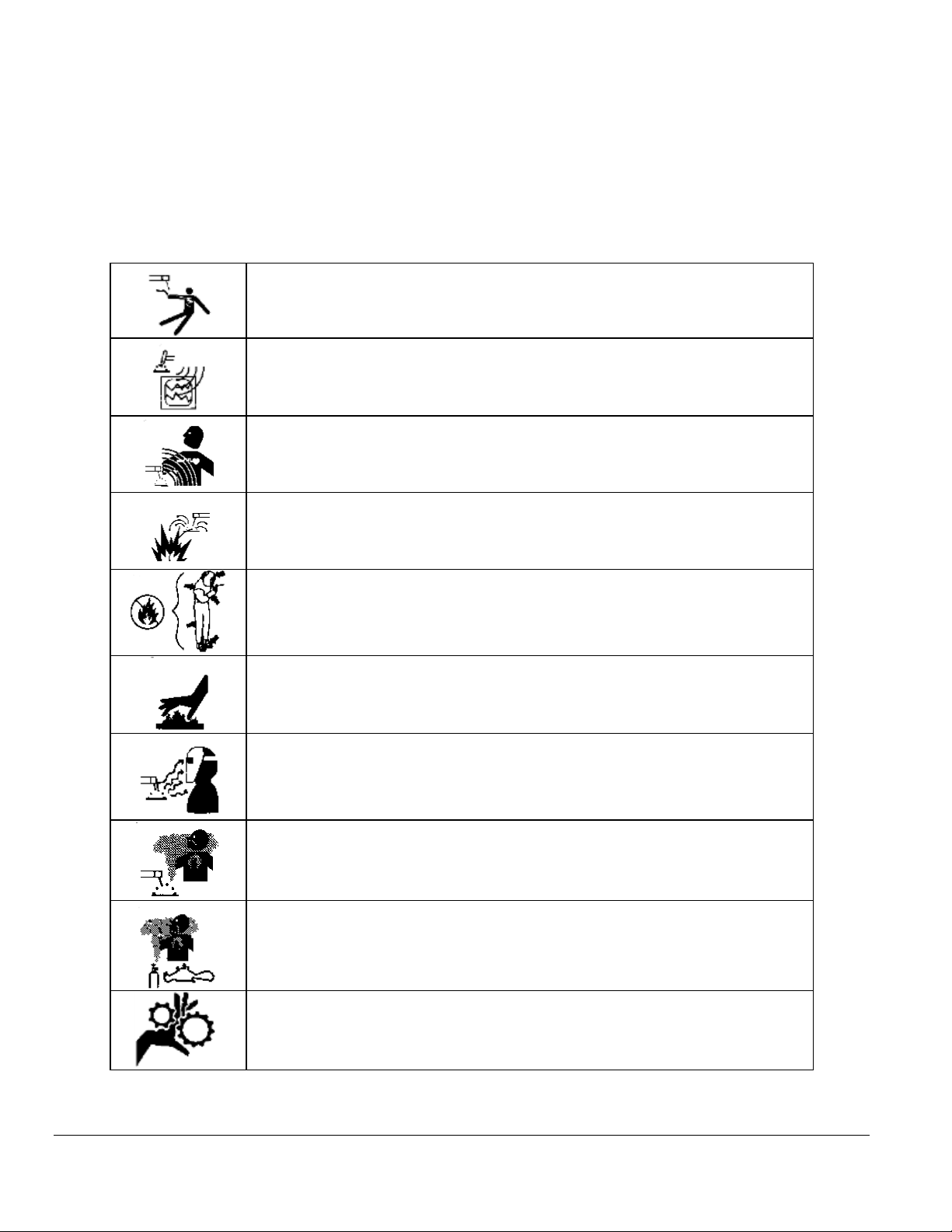
ELECTRIC SHOCK from welding electrode or wiring can kill.
HIGH FREQUENCY RADIO WAVE can cause interference and
sometimes even damage to nearby electronic equipment (such
as computers) that are un-protected.
MAGNETIC FIELDS can affect implanted medical devices.
Wearers of pacemakers should keep away until consulting their
doctor.
Welding can cause FIRE OR EXPLOSIONS. Do not weld near
FLAMMABLE or EXPLOSIVE MATERIALS. Have proper type
of extinguisher in work area.
WEAR NON-FLAMMABLE protective clothing, footwear and
head gear at all times.
HOT PARTS can cause severe burns. Do not touch recently
welded components. Avoid touching torch components and
welding fixtures soon after welding.
ARC RAYS can burn the eyes and skin. The welding arc emits
ultra-violet (UV) radiation and the molten weld gives off infra-
red. Both can burn eyes and skin if unprotected. Suitable eye
and skin protection must be worn.
BUILD UP OF GAS can injure or kill. Weld materials can emit
toxic fumes during welding. WELD ONLY IN AREAS WITH
ADEQUATE VENTILATION.
FUMES AND GASES can be hazardous. Welding produces
fumes and gases. Breathing these fumes and gases can be
hazardous to your health. DO NOT weld in enclosed areas
without proper ventilation or respirators.
MOVING PARTS - Keep hands and fingers clear from fans,
gears, rotors, wire feed, rotation mechanisms.
O P E R A T O R ’ S M A N U A L
1.2 WARNING LABEL DEFINITIONS
The table below contains caution and warning labels for the operation of this equipment.
Before operating this or any welding equipment users should be familiar with “ANSI-49.1
Safety in Welding and Cutting”.
3
M O D E L 2 1 7 W D R
WARNING: Exel factory training is essential for all Welding
Operators and Maintenance Technicians who operate AMI or
EXEL by AMI equipment.
WELDING WIRE and ELECTRODES are sharp and can cause
injury.
MOVING PARTS may cause crush or pinch points.
WARNING: Disconnect the input power to the machine before
opening or servicing. Discharge all circuits that store high
voltage such as capacitor packs. Only AUTHORIZED and
QUALIFIED service personnel should open this equipment.
O P E R A T O R ’ S M A N U A L
4
M O D E L 2 1 7 W D R
WARNING: Read this manual! This document contains information
that could help prevent injury or damage to the equipment.
AC main input, 115/230 volts AC, 50/60 Hz.
On / Off switch (CB-1 main circuit breaker).
Input for the arc shielding gas. An external regulator and flow
indicator must be used.
USB port. For importing and exporting weld schedules from an
external storage device. Devices should not be left plugged in while
welding.
Ethernet port. For networking capability. Devices should not be left
plugged in while welding.
Remote control connection.
Weld head electrode and ground connections.
Output for the arc shielding gas connection.
Weld head control. Intended for AMI and EXEL by AMI weld heads
only.
O P E R A T O R ’ S M A N U A L
1.3 SYSTEM SYMBOLS
The following symbols are present on the Model 217 WDR:
5

M O D E L 2 1 7 W D R
Input Power
Single-Phase
AC
Rated Welding
Output
Welding
Amperage
Range
Max OCV
DC (Uo)
Rated Peak
Starting
Voltage (Up)
Amperes Input
At Rated Load
Output, 50/60Hz,
Single-Phase
KVA
@
Duty
Cycle
59V
15KV
12A
59V
15KV
11A
Chapter
2
O P E R A T O R ’ S M A N U A L
2.0 SPECIFICATIONS
These specifications pertain to the Model 217 WDR power supply only. For weld heads,
refer to the specification sheet of each particular model. For non-AMI supplied equipment
such as gas tanks and regulators, refer to the original manufacturer’s documentation. The
Model 217 WDR is a mobile system that is intended to be hand carried. The supporting
equipment such as weld heads, water coolers, gas regulators, remote controls and
extension cables can also be hand carried. Items such as gas tanks and welding fixtures
should be moved with appropriate equipment and safety precautions. Gas tanks should be
securely anchored to prevent toppling over.
2.1 ELECTRICAL
INPUT POWER DETAIL
The Model 217 WDR can operate on the following Single Phase Auto Adjusting AC inputs:
*DUTY CYCLE is percentage of 10 minutes that unit can weld at rated load without overheating.
Input power must be grounded.
6
M O D E L 2 1 7 W D R
FUNCTION
RANGE
INPUT VOLTAGE
115/230
INPUT AMPERE AT RATED OUTPUT
12A/11A
MAX RECOMMENDED STD. FUSE RATING IN AMPERES
CIRCUIT BREAKER, TIME DELAY
NORMAL OPERATING
15A
20A
MIN. INPUT CONDUCTOR SIZE (AWG)
14
MAX. RECOMMENDED INPUT CONDUCTOR
LENGTH IN FEET (METERS)
91 (28)
MIN. GROUNDING CONDUCTOR SIZE (AWG)
14
POWER SUPPLY HEIGHT
10.5” (267mm)
POWER SUPPLY WIDTH
22.75” (578mm)
POWER SUPPLY DEPTH
18.75” (476mm)
POWER SUPPLY WEIGHT
70 lbs (32 kg)
O P E R A T O R ’ S M A N U A L
OUPUT POWER DETAIL
Straight polarity, constant current DC regulation intended for GTAW welding only. Static
characteristic of all power supplies is flat.
5 to 100 amperes DC using 100 to120 VAC input (15 Ampere service).
5 to 150 amperes DC using 200 to 240 VAC input (30 Ampere service).
CIRCUIT BREAKER – ON/OFF, two pole, 30 Ampere at 250 VAC.
DUTY CYCLE – determined by the AC input voltage and the required output current. The
Model 217 WDR system has an internal thermal sensor that will limit operation should the
temperature exceed the safe operating parameters.
2.2 ELECTRICAL SERVICE GUIDE
2.3 PHYSICAL DIMENSIONS
7

M O D E L 2 1 7 W D R
FUNCTION
RANGE
WELD TYPE (PULSED, NON-PULSED, STEP,
TACK, S^3)
SELECTABLE
NUMBER OF LEVELS
1 - 99 LEVELS
START CURRENT
5 - 150 AMPS
PREPURGE
10 - 1000 SECONDS
POSTPURGE
10 - 1000 SECONDS
TRAVEL START DELAY
0.0 - 100 SECONDS
TRAVEL DIRECTION
CW or CCW
DOWN SLOPE
0.0 – 99.9 SECONDS
LEVEL TIME
0.0 – 999.9 SECONDS
PRIMARY (HIGH) AMPS*
5 – 150 AMPS
BACKGROUND (LOW) AMPS
5 – 150 AMPS
SLOPE TIME
CANNOT EXCEED LEVEL TIME
PRIMARY SPEED (RPM)
0.0 RPM TO WELD HEAD MAX.**
PRIMARY SURFACE SPEED (INCHES PER MINUTE)
CALCULATED
AVERAGE AMPS
CALCULATED
FREQUENCY (Hz.)
CALCULATED
% PRIMARY AMPS
1% – 100%
PRIMARY (HIGH) PULSE TIME
0.01 – 9.99 SECONDS
BACKGROUND (LOW) PULSE TIME
0.01 – 99.9 SECONDS
O P E R A T O R ’ S M A N U A L
2.4 PROGRAMMABLE AND OPERATIONAL FUNCTIONS
SINGLE ENTRY PARAMETERS AND FUNCTIONS
MULTI-LEVEL PARAMETERS AND FUNCTIONS
The following parameters and functions can be programmed in each level to change
value during a weld sequence.
8

M O D E L 2 1 7 W D R
BACKGROUND SPEED (RPM)
0.0 RPM TO WELD HEAD MAX.**
BACKGROUND SURFACE SPEED
CALCULATED
AVERAGE SPEED
CALCULATED
O P E R A T O R ’ S M A N U A L
MULTI-LEVEL PARAMETERS AND FUNCTIONS (con’t)
* For S^3 schedules the PRIMARY AMPS parameter is replaced by START AMPS and
END AMPS parameters.
** TRAVEL parameters are in 0.01 RPM increments.
9
M O D E L 2 1 7 W D R
Chapter
3
O P E R A T O R ’ S M A N U A L
3.0 START-UP
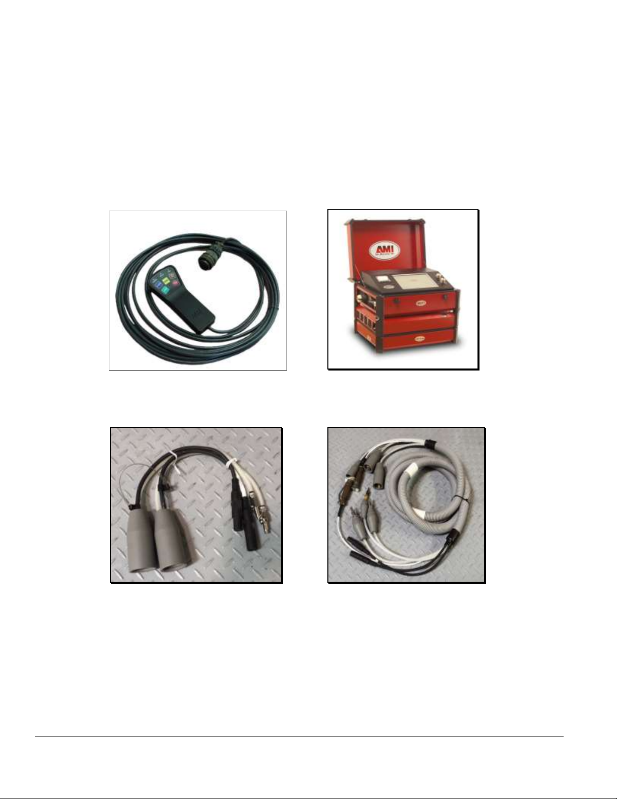
3.1 REQUIRED PERIPHERALS
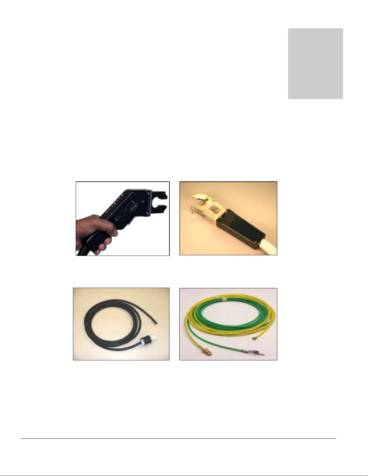
1. An orbital weld head is required to weld with the Model 217 WDR. Shown below is
the EXEL by AMI RDR-05 Rotor Driver and an AMI Model 9-750 orbital weld head.
2. An A.C. power cord rated for 600 VAC service (below left) and gas purge lines are
provided to connect power and inert gas to the power supply.
Note:
A.C. input power cords are shipped WITHOUT an attached utility plug. The customer must
supply their own plug to connect to the main input power source.
10
M O D E L 2 1 7 W D R
O P E R A T O R ’ S M A N U A L
3.2 OPTIONAL PERIPHERALS
All AMI power supplies have their own respective optional remote pendant. This gives the
operator remote welding functions of the Model 217 WDR power supply itself. The optional
cooling unit is recommended for high production or heavy walled (.109”-.154”) welding
applications.
Model 217 WDR Remote Pendant Model 217 WDR with optional Cooling Unit
24 inch “Cheaters” 15 foot “Adapter” cable
Note:
For available options such as remote pendants, water cooling units, longer adapter
cables or extension cables, and more, contact Arc Machines, Inc.
11
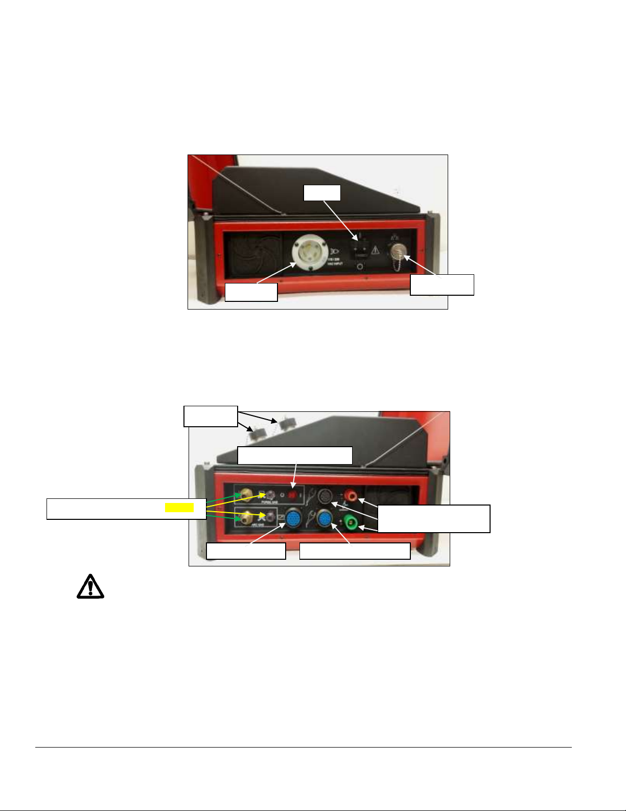
M O D E L 2 1 7 W D R
CB-1
Input A.C.
Arc Gas/ ID Purge Gas Inputs/Outputs
AMI/EXEL by AMI
Weld Head Connections
ID Purge-Manual ON/OFF
Remote Pendant
SWAGELOK Weld Heads
Ethernet port
USB ports
O P E R A T O R ’ S M A N U A L
3.3 POWER SUPPLY CONNECTION
1. Below is a view of the input and output sides of the Model 217 WDR Power Supply with
all connectors visible. Connect the A.C. power cord into a utility power source ranging
from 115/230 volts, 50/60 hertz single phase.
2. Connect Argon (or mixed gas) from an external source to the Model 217 WDR ARC
GAS INPUT connector (I.D. Purge Gas optional), the ARC GAS is monitored by the
computer and MUST be run through the power supply to avoid a FAULT. Connect
the weld head electrode, ground, motor control, and gas line via the 24 inch cheaters or
15 foot adapter cable to the power supply.
The Model 217 WDR is intended for typical GTAW gases ONLY. NEVER CONNECT
OXYGEN OR ACETYLENE to the Model 217 WDR or weld head.
NOTE:
It is recommended to connect the Model 217 WDR to a dedicated A.C. circuit.
Power Input: 115/230 VAC, 50/60 hertz
Purge Input: 5 to 50 psi or 34 to 344 kPa.
12

M O D E L 2 1 7 W D R
O P E R A T O R ’ S M A N U A L
3.4 POWER-UP
Flip ON the main power switch (CB-1). Once the computer boots up the MAIN SCREEN
will appear on the touch screen. The Main Screen allows the operator to CREATE new
weld schedules, access the LIBRARY, OPEN LAST weld schedule that was used,
select certain SETUP features, display information ABOUT Arc Machines, Inc., and
properly SHUT DOWN the power supply.
MAIN SCREEN
Touch LIBRARY pad to open the Model 217 WDR’s internal library which can store over
1,000 complete weld schedules. Each schedule having up to 100 individual levels allowing
for precise manipulation of weld parameters to achieve optimum results based upon your
particular welding application.
13

M O D E L 2 1 7 W D R
Chapter
4
O P E R A T O R ’ S M A N U A L
4.0 LIBRARY AND MEMORY
Touch the LIBRARY pad on the MAIN SCREEN and the Library will appear. The
operator can select and LOAD a weld schedule (selected to weld), DELETE weld
schedules, and COPY weld schedules to/from an external memory device.
LIBRARY
These modes are enabled and displayed only when a memory storage device is connected to the Model 217 WDR’s USB port(s).
The Model 217 WDR’s Library shows the weld schedules available and displays them by:
Programmed Name.
Programmed Actual Outside Diameter of Tube or Pipe.
Programmed Actual Wall Thickness.
Programmed material.
The Operator can select viewing the contents of the Library by specific:
Outside DIAMETER.
WALL Thickness.
MATERIAL.
Or ALL three variables.
14

M O D E L 2 1 7 W D R
O P E R A T O R ’ S M A N U A L
4.1 LOADING A WELD SCHEDULE FROM THE
MODEL 217 WDR LIBRARY
1. Flip the main power switch (CB-1) of the Model 217 WDR to the ON position.
2. Once the computer boots up touch LIBRARY on the MAIN SCREEN.
3. Peruse the LIBRARY, touch the desired weld schedule on the screen, it will become
highlighted.
4. Touch LOAD SCHEDULE.
5. The selected weld schedule will be loaded and the Weld Screen will appear. (Next page).
15

M O D E L 2 1 7 W D R
O P E R A T O R ’ S M A N U A L
WELD SCREEN
From the Weld Screen the operator has access to all power supply, welding and weld
head functions at a touch of the weld screen:
START: Starts the Weld sequence. (Pre purge, arc start, weld sequence, post purge,
rotor returns home, finish weld).
STOP: Terminates weld sequence. (Arc off/rotation stops, post purge, rotor returns
home, finish).
TEST: Starts Test Run sequence. (No purge, no arc, weld schedule sequence, rotor
returns home, finish).
HOME: Manual rotor Return Home command.
PURGE: Manual ON/OFF override of Arc Gas solenoid. (Command to open and close
gas solenoid for setting initial flow rate or continuous arc gas purge flow).
JOG FWD: Allows manual forward rotation of the rotor. Stops when released.
JOG REV: Allows manual reverse rotation of the rotor. Stops when released.
PRINT SCHEDULE: Provides printout of entire weld schedule parameters.
CALIBRATE: If weld heads differ when changing weld schedules, provides automatic
weld head calibration to power supply. Follow on screen prompts to perform calibration.
16

M O D E L 2 1 7 W D R
O P E R A T O R ’ S M A N U A L
POWER ADJUST: This value establishes the min/max % adjustment that the operator
can make to the welding current. On the Weld screen the operator can then adjust the
welding current up or down in 0.1% increments to this value. Once this adjustment is
made and the operator presses the SAVE button, the Power Adjust value will be reset to
0 on the Weld screen and the High and Low current values on the Schedule Screen will
be recalculated to the adjusted value.
ELECTRODE COUNT: Keeps a running count of how many arc starts a particular
electrode has provided. For applications that require electrode change after a specified
amount of arc starts.
WDR: (Weld Data Recording) Samples “real time data” during the weld sequence and
stores weld data (Time, Amps, Arc Volts, RPM) in memory under a programmable weld
identification name. For future export to an EXCEL format and retrieval of data for
identification, documentation and traceability.
SAVE: Offers the operator the ability to overwrite a weld schedule being used using the
same name or copying and renaming the weld schedule being used when a change is
made to the original weld schedule.
SCHEDULE SCREEN: Displays all pertinent data for that particular weld schedule.
Page 1: Tube/Pipe information, Weld Head information, and Electrode data.
Page 2. Weld Schedule Associated Data.
Page 3. Weld Parameters.
HOME: Exits Weld Schedule and returns to MAIN SCREEN.
CURRENT OUTPUT SCREEN: Linear graph displays the AVERAGE current output
throughout the entire weld sequence.
HOME SCREEN: Radial graph displaying relative electrode position from ARC START
throughout the entire weld sequence.
ANALOG METERS:
CURRENT: Analog and numeric display of average current output.
VOLTAGE: Analog and numeric display of ARC VOLTAGE.
PRESSURE: Analog and numeric display of ARC GAS and PURGE GAS
pressure. (dual meter).
ASSOCIATED DATA: Quick reference information of certain parameters and other
pertinent data relevant to that particular weld schedule.
17

M O D E L 2 1 7 W D R
O P E R A T O R ’ S M A N U A L
4.2 COPYING WELD SCHEDULES FROM THE MODEL 217
WDR LIBRARY TO AN EXTERNAL MEMORY DEVICE
1. Open LIBRARY. Insert the external memory device into the Model 217 WDR USB port.
2. Select (highlight) one weld schedule to be copied to the external memory device.
3.Touch COPY TO EXTERNAL MEMORY to copy that one weld schedule, or touch
COPY ALL TO EXTERNAL MEMORY if you want the entire Model 217 WDR
library copied to the external memory device.
Note: Should the weld schedule(s) you are trying to copy from the Model 217 WDR library
already exist in the external memory device the following screen be displayed:
18

M O D E L 2 1 7 W D R
O P E R A T O R ’ S M A N U A L
4. The screen below will be displayed to verify if one weld schedule was copied successfully
to the external memory device.
5. OR the screen below will be displayed to verify if the entire Model 217 WDR
library has been copied successfully to the external memory device.
19

M O D E L 2 1 7 W D R
O P E R A T O R ’ S M A N U A L
6. Touch OK to clear verification screen. Touch EXTERNAL MEMORY display.
7. Verify that the weld schedule or schedules have been copied to the external memory
device.
8. Remove external memory device.
20

M O D E L 2 1 7 W D R
O P E R A T O R ’ S M A N U A L
4.3 COPYING WELD SCHEDULES FROM AN EXTERNAL
MEMORY DEVICE TO THE MODEL 217 WDR LIBRARY
1. Open LIBRARY. Insert external memory device in the Model 217 WDR USB port.
2. Touch EXTERNAL MEMORY to open and display external memory device library.
3. Select (highlight) one weld schedule to be copied to the Model 217 WDR library.
4. Touch COPY TO M217 WDR to copy that one weld schedule, or touch COPY ALL
TO M217 WDR if you want the entire external memory library copied to the Model
217 WDR library.
Note: Should the weld schedule(s) you are trying to copy from the external memory device
already exist in the Model 217 WDR library the following screen be displayed:
21

M O D E L 2 1 7 W D R
ALL SCHEDULES COPIED TO M217.
O P E R A T O R ’ S M A N U A L
5. The screen below will be displayed to verify if one weld schedule was copied
successfully to the Model 217 WDR library.
6. OR the screen below will be displayed to verify if the entire external memory
library has been copied successfully to the Model 217 WDR library.
22

M O D E L 2 1 7 W D R
O P E R A T O R ’ S M A N U A L
7. Touch OK to clear verification screen. Touch M217 WDR display.
8. Verify that the weld schedule or schedules have been copied to the Model 217 WDR
library.
9. Remove external memory device.
23

M O D E L 2 1 7 W D R
Chapter
5
O P E R A T O R ’ S M A N U A L
5.0 CREATING WELD SCHEDULES
5.1 CREATING A MANUAL 4 LEVEL WELD SCHEDULE
1. From the MAIN SCREEN touch the CREATE SCHEDULE pad and the create schedule
menu will be displayed. Select MANUAL SCHEDULE.
2. Page 1 of the SCHEDULE SCREEN will be displayed. Select and enter all required
MATERIAL, WELD HEAD and ELECTRODE parameters using the numerical key pad.
24
M O D E L 2 1 7 W D R
O P E R A T O R ’ S M A N U A L
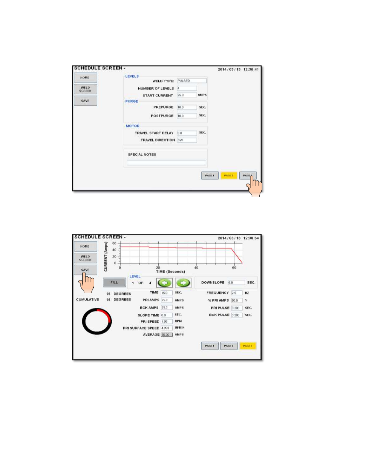
3. Press Page 2. Select and enter all required LEVELS, PURGE and MOTOR
parameters. You may also enter any SPECIAL NOTES that you may have.
4. Press Page 3. Select and enter all required WELDING parameters for all 4 levels.
5. Press SAVE.
25

M O D E L 2 1 7 W D R
O P E R A T O R ’ S M A N U A L
6. The SCHEDULE NAME screen will be displayed. The default schedule name is based on
the tube O.D., wall thickness and material you entered when creating this weld schedule.
You may save it as is or use the keypad to assign your own personal weld schedule name.
Press SAVE when finished.
7. Pressing SAVE will store all data in the library under the SCHEDULE NAME you selected
and the WELD SCREEN will be displayed with the schedule name on top.
8. The Model 217 WDR is now loaded with the weld schedule and is in STANDBY mode,
ready to weld.
26

M O D E L 2 1 7 W D R
O P E R A T O R ’ S M A N U A L
5.2 CREATING AN AUTOMATIC 4 LEVEL WELD SCHEDULE
1. From the MAIN SCREEN touch the CREATE SCHEDULE pad and the create schedule
menu will be displayed. Select AUTO SCHEDULE.
2. The AUTO SCHEDULE screen will be displayed. Select and enter all required O.D., WALL,
MATERIAL and WELD HEAD parameters using the numerical key pad.
3. Press the AUTO PULSED pad.
27

M O D E L 2 1 7 W D R
O P E R A T O R ’ S M A N U A L
4. The AUTO SCHEDULE NAME screen will be displayed. The default schedule name is
based on the tube O.D., wall thickness and material you entered when creating this weld
schedule. You may save it as is or use the keypad to assign your own personal weld
schedule name. Press SAVE when finished.
5. Pressing SAVE will store all data in the library under the SCHEDULE NAME you
selected and the WELD SCREEN will be displayed with the schedule name on top.
6. The Model 217 WDR is now loaded with the weld schedule and is in STANDBY mode,
ready to weld.
28

M O D E L 2 1 7 W D R
O P E R A T O R ’ S M A N U A L
5.3 CREATING AN AUTO STEP WELD SCHEDULE
1. From the MAIN SCREEN touch the CREATE SCHEDULE pad and the create schedule
menu will be displayed. Select AUTO SCHEDULE.
2. The AUTO SCHEDULE screen will be displayed. Select and enter all required O.D., WALL,
MATERIAL and WELD HEAD parameters using the numerical key pad.
3. Press the AUTO STEP pad.
29

M O D E L 2 1 7 W D R
O P E R A T O R ’ S M A N U A L
4. The AUTO SCHEDULE NAME screen will be displayed. The default schedule name is
based on the tube O.D., wall thickness and material you entered when creating this weld
schedule. You may save it as is or use the keypad to assign your own personal weld
schedule name. Press SAVE when finished.
5. Pressing SAVE will store all data in the library under the SCHEDULE NAME you
selected and the WELD SCREEN will be displayed with the schedule name on top.
6. The Model 217 WDR is now loaded with the weld schedule and is in STANDBY mode,
ready to weld.
30

M O D E L 2 1 7 W D R
O P E R A T O R ’ S M A N U A L
5.4 CREATING AN AUTO TACK WELD SCHEDULE
1. From the MAIN SCREEN touch the CREATE SCHEDULE pad and the create schedule
menu will be displayed. Select AUTO SCHEDULE.
2. The AUTO SCHEDULE screen will be displayed. Select and enter all required O.D., WALL,
MATERIAL and WELD HEAD parameters using the numerical key pad.
3. Press the AUTO TACK pad.
31

M O D E L 2 1 7 W D R
O P E R A T O R ’ S M A N U A L
4. The TACK PARAMETERS screen will be displayed. You can select the amount of
PENETRATION PERCENTAGE (0% to 126%) desired, the NUMBER OF TACKS (1 to 40)
desired, and the TACKING PATTERN – SEQUENTIAL (consecutive) or BALANCED (180
degrees opposite each other) desired. Press O.K. when set.
5. The AUTO SCHEDULE NAME screen will be displayed. The default schedule name is
based on the tube O.D., wall thickness and material you entered when creating this weld
schedule. You may save it as is or use the keypad to assign your own personal weld
schedule name. Press SAVE when finished.
32

M O D E L 2 1 7 W D R
O P E R A T O R ’ S M A N U A L
6. Pressing SAVE will store all data in the library under the SCHEDULE NAME you
selected and the WELD SCREEN will be displayed with the schedule name on top.
6. The Model 217 WDR is now loaded with the weld schedule and is in STANDBY mode,
ready to tack.
5.5 CREATING AN AUTO S^3 (S cubed) WELD SCHEDULE
1. From the MAIN SCREEN touch the CREATE SCHEDULE pad and the create schedule
menu will be displayed. Select AUTO SCHEDULE.
2. The AUTO SCHEDULE screen will be displayed. Select and enter all required O.D., WALL,
MATERIAL and WELD HEAD parameters using the numerical key pad.
33

M O D E L 2 1 7 W D R
O P E R A T O R ’ S M A N U A L
3. Press the AUTO PULSED S^3 pad.
4. The AUTO SCHEDULE NAME screen will be displayed. The default schedule name is
based on the tube O.D., wall thickness and material you entered when creating this weld
schedule. You may save it as is or use the keypad to assign your own personal weld
schedule name. Press SAVE when finished.
5. Pressing SAVE will store all data in the library under the SCHEDULE NAME you
selected and the WELD SCREEN will be displayed with the schedule name on top.
34

M O D E L 2 1 7 W D R
O P E R A T O R ’ S M A N U A L
6. The Model 217 WDR is now loaded with the weld schedule and is in STANDBY mode,
ready to weld.
7. Below is an example of an S^3 (pronounced S cubed) weld, it is named for the three S’s
defining the weld (Single Slope, Single pass). It is a linear reduction of current from a
START AMPS to an END AMPS with a LOW AMP PULSATION for an AVERAGE AMP
OUTPUT.
35

M O D E L 2 1 7 W D R
Chapter
6
O P E R A T O R ’ S M A N U A L
6.0 SETUP
6.1 PROGRAMMING BASIC SETUP FEATURES
1. From the MAIN SCREEN touch the SETUP pad.
2. The SETUP screen will be displayed.
3. From the SETUP screen is where the internal CLOCK (local time and year) is set, the
libraries UNITS OF MEASURE (English or Metric) is selected, and the current override
POWER ADJUST minimum and maximum limits are set.
36
M O D E L 2 1 7 W D R
O P E R A T O R ’ S M A N U A L
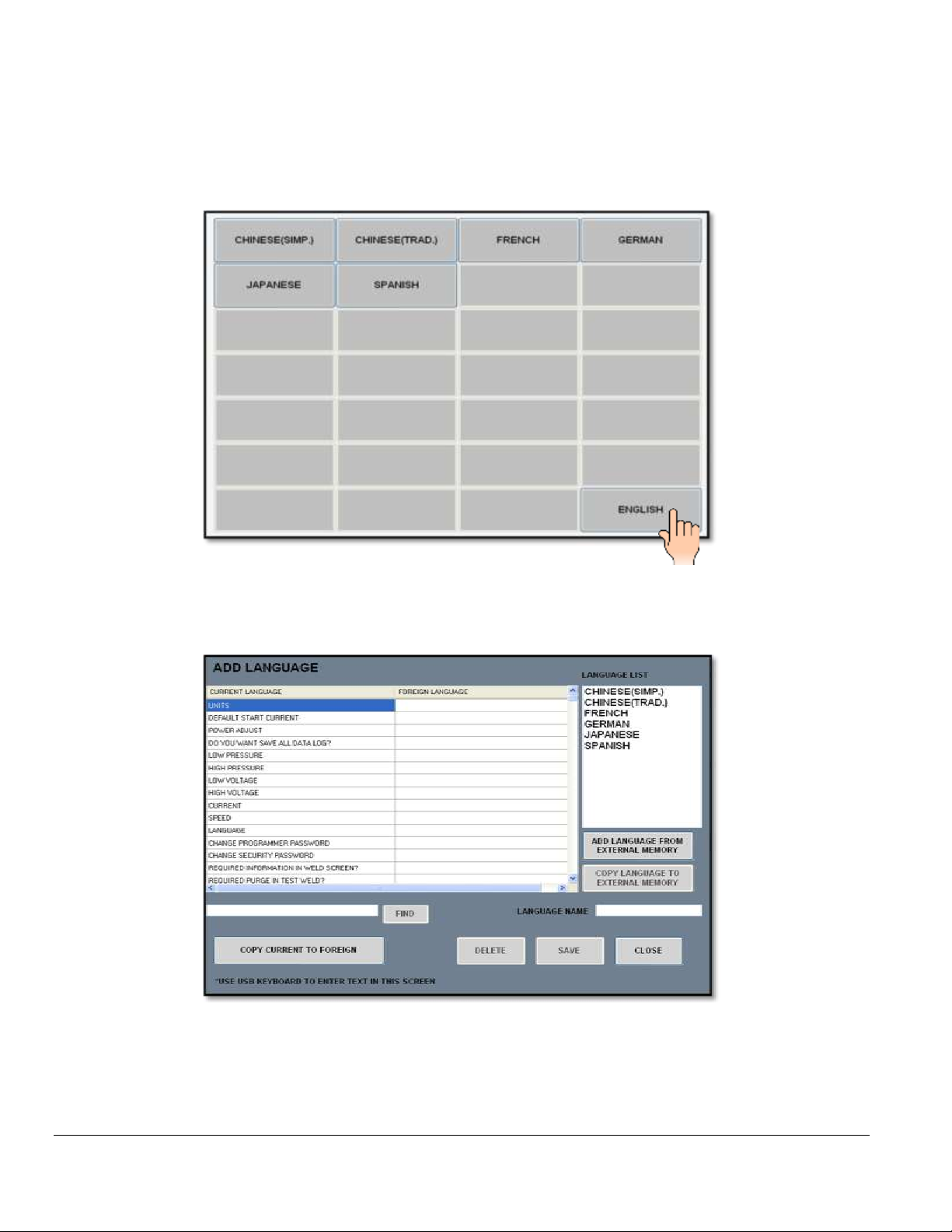
6.2 PROGRAMMING THE LANGUAGE FEATURES
1. The LANUAGE pad displays the current languages available to use in the language
library:
2. Select CHINESE, FRENCH, GERMAN, JAPANESE, SPANISH or ENGLISH.
3. The ADD LANGUAGE pad displays the language menu:
4. The ADD LANGUAGE screen allows IMPORTING and EXPORTING different
languages from an external memory device, MODIFIES selected words to CUSTOM
WORDS, DELETES whole language files, and SAVES any changes made to existing
languages.
37

M O D E L 2 1 7 W D R
O P E R A T O R ’ S M A N U A L
6.3 PROGRAMMING THE PASSWORD FEATURES
The CHANGE PROGRAMMER PASSWORD and CHANGE SECURITY PASSWORD
pads allow management/supervisors to set passwords so as to minimize or limit operator
access to certain screens and operational features of the Model 217. This will determine
what the operator can do, cannot do, or is limited in doing with the Model 217.
! NOTE !
ALL M217 WDR LEAVE THE FACTORY WITH NO PASSWORDS SET (BLANK)!
OPERATORS WILL HAVE ACCESS TO ALL SCREENS, SETTINGS, AND
FUNCTIONS.
SECURITY PASSWORD: Required to unlock limited access to the Model 217 WDR.
Allows access to LIBRARY and OPEN LAST only. Weld schedules may only be loaded
from the LIBRARY and welded with. No permanent program changes are allowed.
PROGRAMMER PASSWORD: Required to unlock entire access to the Model 217
WDR. Allows access to CREATE SCHEDULE, LIBRARY, OPEN LAST and SETUP.
All features are accessible and all functions are available, any and all programmable
changes are allowed and can be permanently saved in the library.
1. To CHANGE SECURITY PASSWORD, enter OLD PASSWORD. (From the factory the
passwords are BLANK, i.e. no numbers).
2. Enter NEW PASSWORD (up to 5 numbers).
3. CONFIRM new password (re-enter same numbers).
4. NEW PASSWORD IS SET will appear on screen if password is set properly.
5. Repeat to set CHANGE PROGRAMMER PASSWORD.
38

M O D E L 2 1 7 W D R
Chapter
7
O P E R A T O R ’ S M A N U A L
7.0 ALARMS AND FAULTS
7.1 PROGRAMMING ALARM SETTINGS
ALARM SETTINGS are only accessible using a 5 digit “1-Day Programmer Password”,
which is only available by calling AMI Technical Support (In USA 818-896-9556).
1. From the MAIN SCREEN touch the SETUP pad. The SETUP SCREEN will be
displayed. Touch the CHANGE PROGRAMMER PASSWORD pad and the password
screen will appear.
2. Enter and confirm the 5 digit 1-Day Programmer Password. NEW PASSWORD IS SET
will appear on the screen if password is set properly.
3. Touch the HOME pad on the SETUP SCREEN to return to the MAIN SCREEN.
4. From the MAIN SCREEN follow standard SHUT DOWN procedure.
5. Once the MAIN SCREEN turns OFF, flip the MAIN POWER SWITCH (CB-1) to the
OFF position.
39

M O D E L 2 1 7 W D R
O P E R A T O R ’ S M A N U A L
6. Wait 10 seconds, flip CB-1 to the ON position, wait for computer to boot up.
7. Once boot up is complete, the MAIN SCREEN will be displayed. On the MAIN SCREEN
touch the SETUP pad.
8. The MAIN SCREEN will prompt you for the PROGRAMMER PASSWORD.
9. ENTER the 5 digit 1-Day Programmer Password.
10. The ALARM SETTINGS will be displayed on SETUP SCREEN.
40

M O D E L 2 1 7 W D R
OK
MOTOR STALL – CHECK
FOR OBSTRUCTION
OK
BAD ARC START – ARC
FAILED TO START.
CHECK EQUIPMENT,
CONNECTIONS AND
ELECTRODE
O P E R A T O R ’ S M A N U A L
7.2 ALARM SETTINGS
LOW PRESSURE: The lowest allowable pressure desired for the purge inlet of the power
supply. Low Pressure value should be set to 0.0. Inadequate flow will trigger a flow
alarm on the touch screen.
HIGH PRESSURE: The highest allowable pressure desired for the purge inlet of the power
supply. The maximum value for this field is 50.0 psi. Over pressure will trigger a flow
alarm on the touch screen.
LOW VOLTAGE: The minimum allowable arc voltage. This setting is often used to
indicate a stub out or insufficient gap between the electrode and work. This value is
defaulted at 4.0 volts.
HIGH VOLTAGE: The maximum allowable arc voltage. This setting is used to indicate
excessive gap between the electrode and work and other anomalies such as insufficient or
missing purge. This value is defaulted at 25.0 volts.
CURRENT: The tolerance in terms of % variation from the average current, as measured
in feedback. This should be set based on the requirements of the welding operation. The
variation is +/- 3%.
SPEED: The tolerance in terms of % variation from the programmed speed, as measured
in feedback. This should be set based on the requirements of the welding operation. The
variation is +/- 3%.
DEFAULTS: On the lower right of the ALARM SETTING SCREEN there is a DEFAULTS
pad. Touching this pad allows the user to quickly re-populate the ALARM SETTING
values with the factory defaults.
7.3 ALARMS AND FAULTS
The following FAULT SCREENS appear when the value of the welding parameter
has been exceeded, as programmed in the ALARM SETTING screen.
1. The message below left will appear if the arc fails to start. The message below
right will appear if the weld head fails to rotate and/or is jammed.
41

M O D E L 2 1 7 W D R
UNIT OVERHEATED
PURGE PRESSURE IS
NOT RECOMMENDED
VALUE
GAS FAULT
VOLTAGE IS BELOW
RECOMMENDED VALUE
VOLTAGE IS ABOVE
RECOMMENDED VALUE
O P E R A T O R ’ S M A N U A L
2. The message below left will appear if arc voltage goes above the set value. The
message below right will appear if arc voltage goes below the set value.
3. The message below left will appear if the gas fails to flow to the weld head. The
message below right will appear if the input gas pressure is below minimum
requirement.
4. The message below will appear if the internal temperature of the unit rises above
maximum value as registered by the thermocouple.
7.4 PRINTING
To print from the power supply, touch PRINT SCHEDULE on the WELD SCREEN.
The onboard printer will print the weld schedule and applicable associated data.
42

M O D E L 2 1 7 W D R
O P E R A T O R ’ S M A N U A L
7.5 PROPER SHUTDOWN OF THE MODEL 217 WDR
1. Touch HOME from whatever screen you are on to return to the MAIN SCREEN.
2. Touch SHUT DOWN.
3. The screen above will appear to CONFIRM SHUT DOWN. Touch SHUT DOWN.
4. The MAIN SCREEN will reappear for approximately 5 seconds before screen turns BLACK
(computer turns OFF).
5. Flip the MAIN POWER SWITCH (CB-1) to the OFF position.
43

M O D E L 2 1 7 W D R
Chapter
8
O P E R A T O R ’ S M A N U A L
8.0 MAINTENANCE AND TROUBLESHOOTING
Always disconnect the AC power cable from the line voltage before
attempting to work on this welding power supply.
There are no user serviceable components located inside the Model 217 WDR. Do not
open the unit in an attempt to repair it. Contact Arc Machines, Inc. if the unit is
malfunctioning, or suspected of being broken. As such, no wiring diagram or internal circuit
drawing is provided.
8.1 GENERAL MAINTENANCE
CLEANING EXTERIOR AND INTERIOR SURFACES - Prolonged use in dusty shop or
outside environments may cause the outside surfaces to accumulate a coating of dirt and
dust. Do not use shop air (usually too wet) to blow dust particles away from the panels.
Use a vacuum cleaner with a soft brush. Where a vacuum brush cannot reach, use a clean,
soft paint brush and then vacuum.
INPUT/OUTPUT PANEL CONNECTIONS - Periodic inspection of the Model 217 WDR
panel and the ground, electrode and gas quick-disconnects on all cables should be
performed. Damaged, dented or deformed connectors may cause poor or unsafe operation
or gas leakage. The O-rings inside the weld head ground, electrode and gas quickdisconnects should be periodically cleaned and re-greased.
Precautions to follow for storing or handling:
Always keep weld heads in the protective containers they are shipped in, or
optional carrying case, until ready for use
44

M O D E L 2 1 7 W D R
O P E R A T O R ’ S M A N U A L
Always keep the protective boots and dust caps on all connectors and fittings
until cables are ready to install. A major cause of downtime in any automatic
welding system is improper care and use of cables.
Take extreme care to avoid dropping the power supply or the weld heads.
Always disconnect the power input cable from the junction box or wall-
plug before cleaning the unit.
DO NOT USE acid, corrosives or any liquid substance on the Model 217 WDR
or any weld head. When cleaning, use only a light solution of isopropyl alcohol on a
soft cloth.
DO NOT ADD lubrication such as graphite, oil or grease to the weld head or
power supply unless it is specified in the operation manual for that equipment.
8.2 TROUBLESHOOTING
The Model 217 WDR has the ability to monitor certain functions. If they are not working
correctly a system fault will alert the operator to the problem.
When a System Fault occurs prior to or during welding it is required for the operator to clear
the fault condition before welding. When a fault occurs during sequence or attempting
sequence the FAULT SCREEN will appear.
Some faults are only temporary and the fault is corrected when the arc goes out. But all
faults will cause the FAULT SCREEN to appear and let the operator know why the
sequence was stopped.
The following is a general description of the cause of each type of fault and some
recommendation for correction. In all cases, when the fault is corrected the operator must
press the OK key to clear the FAULT SCREEN.
1. TEMP - The Model 217 WDR has an internal temperature sensor (thermal switch). If
the power supplies internal temperature rises above the safe limit, a TEMP fault
occurs. This can only occur if there is some type of blockage of air circulation, fan
failure or component failure within the power supply or the system is being operated in
ambient air temps above or below its rating of 0 degrees C (32F) and 45 degrees C
(104F), 95% humidity (non condensing).
45

M O D E L 2 1 7 W D R
O P E R A T O R ’ S M A N U A L
This fault should only occur during an actual weld sequence. If it occurs when the
machine is not welding then a serious internal problem exists. In this case turn the
Power Supply OFF and call an Arc Machines Service representative.
If it occurs during welding, check for blockage of the air intakes and exhaust on the
sides of the machine.
2. GAS - This fault will only occur at the beginning of or during a weld sequence. If the arc
gas flow through the system should stop, or fall below 7 CFH a fault will occur.
Check that the gas source (user supplied) is turned on and that adequate gas is
available. Check all gas hoses and connections for free flow, this is usually the
problem.
If there is no problem with the source or with hoses and connection then an internal
failure of the flow switch, solenoid or internal hosing is possible. Contact an Arc
Machines Service representative.
3. ARC VOLTS (low) or STUB OUT - This fault will only occur when an arc is present
and the electrode gets too close to the work. If the arc voltage gets too low (below 4
volts) or the electrode should touch the weld puddle an ARC VOLT fault will
occur. It creates an ALL STOP and does not actuate the “return to home”
function after POSTPURGE.
4. ARC VOLTS (high) - If the arc voltage is too high (above 25 volts) during a weld
sequence this fault will occur. It usually occurs if a hole should be made in the weld,
causing the arc to wander over to the far side of the hole. The most common causes
of this is either poor fit up or excessive I.D. gas pressure, causing the weld to blow out
from the I.D. and creating a hole.
5. BAD START - If for any reason the Model 217 WDR cannot establish a stable arc (at
the end of PREPURGE) the system will display a BAD START fault. There can be
several reasons for this to occur. The most common are poor ground or electrode
connections, contaminated gas or contaminated electrode. Another common cause of
a BAD START is too short of a PREPURGE time. This is especially true when a
system or weld head is being used for the first time in a shift. While it sits (unused)
atmosphere can propagate into the cables. Before performing the first weld of a shift,
use the manual “PURGE” for a minute or two to initially purge (clear) the gas lines.
Note
Arc Machines recommends 2% Ceriated welding electrodes. They have proven to be
much more effective than Thoriated electrodes for RF transmission and are reported to
have longer life than 2% Thoriated Electrodes.
46

M O D E L 2 1 7 W D R
O P E R A T O R ’ S M A N U A L
47
 Loading...