


MODEL 207A AND 207A-1
DATE
A
N/A
OPERATION MANUAL
NOTICE
This document and the information contained herein is the property of Arc Machines, Inc..
It is proprietary and submitted and received in confidence. It shall be used only for the
purpose for which it is submitted and shall not be copied in whole or in part without the
prior express written permission of Arc Machines, Inc.
The information in this document has been carefully reviewed and is believed to be
accurate. However, no responsibility is assumed for inaccuracies.
Information and instructions in this document are subject to change and Arc Machines, Inc.
reserves the right to change specifications and data without notice.
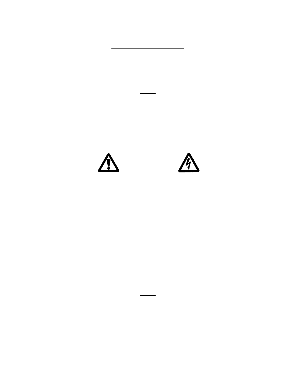
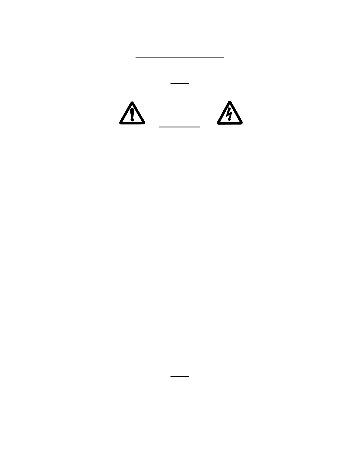
WARNING
The nature of the GTAW process creates some POTENTIAL HAZARDS. In accordance
with international safety regulations the EXCLAMATION SYMBOL indicates that this
equipment is considered HAZARDOUS until an operator has been made aware of these
POTENTIAL HAZARDS by READING THIS MANUAL. The LIGHTNING FLASH
SYMBOL indicates that there are potential electrical hazards. The use and display of these
symbols make it the OPERATOR’S RESPONSIBILITY TO INSURE THAT HE HAS
READ AND/OR BEEN MADE AWARE OF ALL OF THE SAFETY-RELATED ITEMS
CONTAINED IN THIS MANUAL.
Publication date : First Edition - August 15, 1989
Copyright 1989 by Arc Machines, Inc.
All rights reserved
REV. DCO # CHANGE DESCRIPTION
Revised Pg I, ii, iii,iv 9/29/93 GPE
B 2357 Revised to include required IEC-974 information 8/15/96 GPE
C 3059 Added M227/207-CW info: pg. iv, v, 1.1, 3.7, 4.12, 7.5, 7.7,
8.1, 8.2, 8.3.
D 3583 Revised page 7.4 Step 13 add new Current Offset
adj.
E 3684 Removed ref to Miller coolant page 8.2 7/20/00 GPE
04/20/98 GPE
3/20/00 GPE
APR
F 5779 Removed 207A-HP (OBS) 8/10/10 DC
Doc. No. 740044
Rev F
i

MODEL 207A AND 207A-1
OPERATION MANUAL
EFFECTIVITY
Features and operation of the Model 207A, Model 207A-1 are derived mostly from
SOFTWARE. This document is based on the latest STANDARD version of
SOFTWARE at the time of last revision (see revision page).
Some deviations in actual operation, from this document, are possible depending on
the software version of a particular machine. Please feel free to contact Arc Machines
Service Department for documentation or information on how software updates effect
this document.
ii
Doc. No. 740044
Rev F

MODEL 207A AND 207A-1
OPERATION MANUAL
TABLE OF CONTENTS
SECTION DESCRIPTION PAGE
SECTION I INTRODUCTION
1.0 Introduction 1.1
1.1 Safety Precautions 1.2
1.2 Operational Precautions 1.5
1.3 Shock Hazard Warning 1.7
SECTION II SPECIFICATIONS
2.0 Electrical 2.1
2.1 Physical Construction 2.3
2.2 Programmable Functions and Ranges 2.3
2.3 Multi-Level Functions 2.3
2.4 Ambient Temperature Range 2.4
2.5 Cable Operating Length Limits 2.4
SECTION III INSTALLATION
3.0 Inspection 3.1
3.1 Power Connections 3.1
3.2 Welding Gas Connections 3.2
3.3 Adapter Cable to M-207A Installation 3.7
3.4 Weld Head Installation 3.7
SECTION IV SYSTEM FUNCTIONS
4.0 Introduction 4.1
4.1 Functional Description, General 4.1
4.2 Weld Library and Weld Description 4.3
4.3 Weld Sequence 4.3
4.4 Panel Keys 4.9
4.5 Operate Mode Switch 4.11
4.6 Faults 4.12
4.7 Sensor 1,2,3 Faults 4.13
4.8 Set-Up Functions 4.13
4.9 Glossary of Abbreviations 4.15
4.10 Glossary of Terms 4.16
iii
Doc. No. 740044
Rev F

MODEL 207A AND 207A-1
OPERATION MANUAL
TABLE OF CONTENTS
SECTION DESCRIPTION PAGE
SECTION V OPERATION
5.0 Introduction 5.1
5.1 Initial Power On 5.1
5.2 Use of Next/Prev 5.2
5.3 Weld Schedule Selection 5.4
5.4 Viewing Function Values 5.5
5.5 Overriding Function Values Before Seq 5.6
5.6 Overriding Function Values During Seq 5.7
5.7 Set Up Functions 5.7
5.8 Auto Rotation Calibration 5.11
5.9 Manual Rotation Calibration 5.13
5.10 Welding Operation 5.15
5.11 Printer Operation 5.16
SECTION VI PROGRAMMING
6.0 Introduction 6.1
6.1 Create A Weld Schedule 6.1
6.2 Modify A Weld Schedule 6.4
6.3 Copy a Weld Schedule 6.5
6.4 Transfer/Receive A Weld Schedule 6.6
6.5 Delete A Weld Schedule 6.7
SECTION VII CALIBRATION
7.0 Introduction 7.1
7.1 Equipment Required 7.1
7.2 Current Servo 7.2
7.3 General Maintenance 7.5
7.4 System Fault Corrections 7.6
7.5 Error Messages 7.9
7.6 Miscellaneous Maintenance Items 7.10
SECTION VIII OPTIONS
8.0 Introduction 8.1
8.1 M227/207-CW & M207-CW Cooling Unit 8.1
8.2 M-207-RP Remote Pendant 8.3
8.3 M-207-EMM External Memory Module 8.7
iv
Doc. No. 740044
Rev F

MODEL 207A AND 207A-1
OPERATION MANUAL
TABLE OF CONTENTS
LIST OF ILLUSTRATIONS
FIGURE DESCRIPTION PAGE
FIGURE 1 SYSTEM CONFIGURATION 1.4
FIGURE 2 INSTALLATION LOCATIONS 3.3
FIGURE 3 AC POWER SET-UP 3.4
FIGURE 4 CABLE CONNECTIONS 3.5
FIGURE 5 SEQUENCE TIMING CHART 4.7
FIGURE 6 PANEL KEY LOCATIONS 4.8
FIGURE 7 USE OF NEXT/PREV KEYS 5.3
FIGURE 8 M227/207-CW & M207-CW INSTALLATION 8.6
v
Doc. No. 740044
Rev F

MODEL 207A AND 207A-1
OPERATION MANUAL
SECTION I - INTRODUCTION
1.0 INTRODUCTION
This manual is intended to assist users of this equipment in set up and basic
operation. Automatic fusion welding requires a good deal of operator expertise
which requires AMI supplied training. THIS MANUAL IS NOT INTENDED AS
A SUBSTITUTE FOR THAT TRAINING.
The basic Model 207A (M-207A) welding power supply is part of a complete
welding system intended for fusion welding of metal tubes, pipes and fittings (see
Figure 1). The complete system consists of the M-207A power supply, adapter
cable, gas lines and any of the AMI Model 9 (M-9) series of tube welding heads
(M-9 heads sold separately).
The M-207A power supply provides GTAW current with pulsation controls, high
frequency arc starting, purge gas controls, weld head arc rotation and automatic
timing functions. The M-207A is supplied (as standard) ready to weld. Users
need only to supply input AC power, regulated gas source with flow meter and the
appropriate weld head or manual torch.
Some operating conditions may require optional components such as the remote
pendant option (M-207-RP), weld head cooling unit option (M227/207-CW or
M207-CW) and extension cables. The M-207A family of options also includes
quality assurance options such as chart recorders and Weld Data Recording
Software.
The system can also be used as a manual welding power source using an optional
manual torch with a variety of manual welding options such as a variable current
foot controller or a remote start/stop switch.
NOTE
In-depth weld development instructions, weld head set-up, maintenance and
troubleshooting are contained in other manuals, documents and training classes
and are not included in this manual. Contact your AMI representative for more
information about these items.
1.1
Doc. No. 740044
Rev F
MODEL 207A AND 207A-1
OPERATION MANUAL
SECTION I - INTRODUCTION
1.1 SAFETY PRECAUTIONS
This section contains cautions and warnings concerning the operation of this
equipment and welding equipment in general. However, in addition to reading
this manual and before operating this or any welding equipment, users should
reference and be familiar with “ANSI-49.1 Safety in Welding and Cutting”.
This standard is published by the American National Standards Institute and the
American Welding Society.
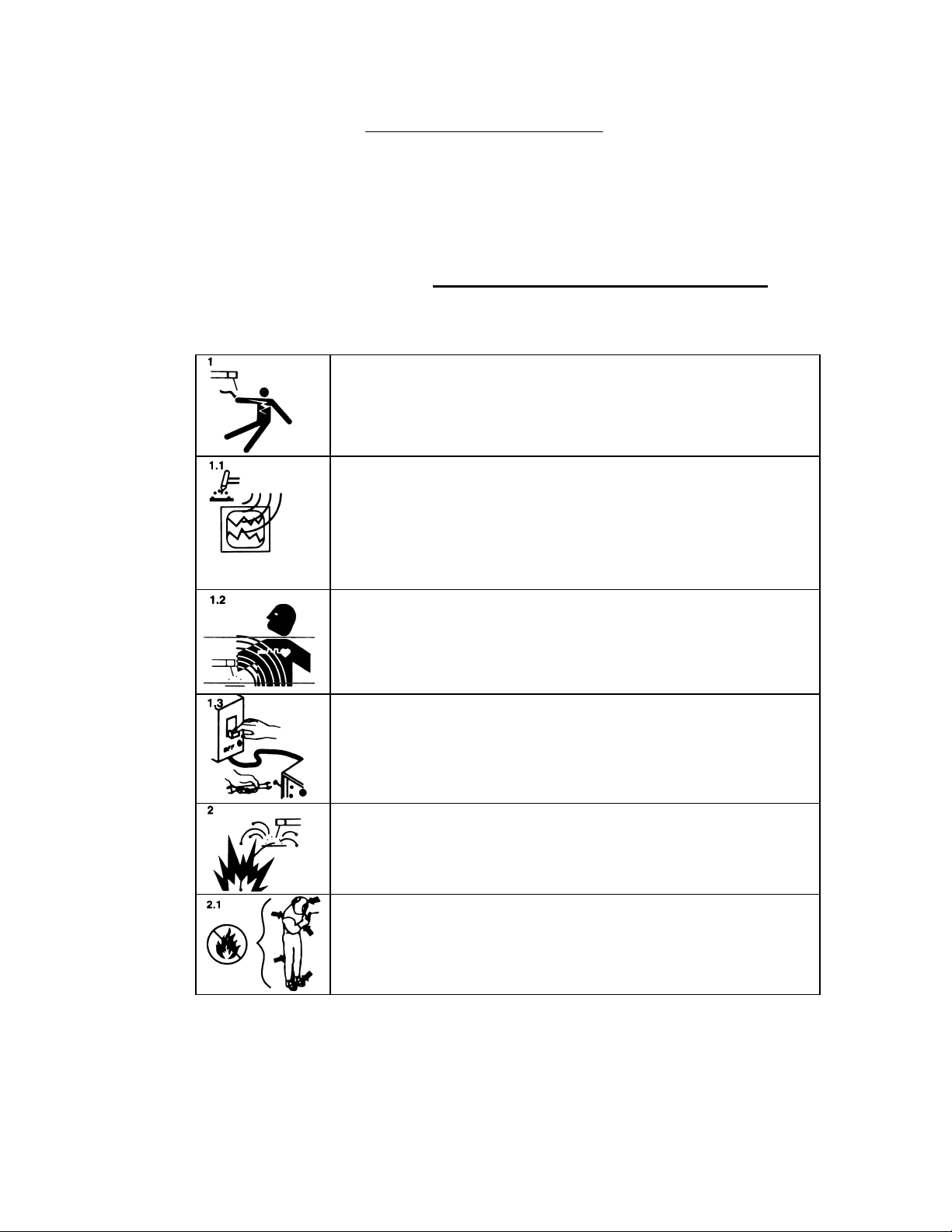
WARNING: Touching energized electrical parts can cause
fatal shocks and burns. When in weld sequence the electrode
and work are electrically energized. Incorrectly installed or
improperly grounded equipment is a hazard.
WARNING: This equipment is authorized to use a type of
arc starter that produces a High Frequency Radio Wave
(sometimes called HF and/or RF Starting). It can cause
interference and sometimes even damage to nearby electronic
equipment (such as computers) that are un-protected or poorly
protected against such interference.
WARNING: Magnetic Fields from High Currents can affect
pacemakers. PACEMAKER WEARERS KEEP AWAY
UNTIL CONSULTING YOUR DOCTOR.
WARNING: Disconnect the input power to the machine
before opening or servicing. Discharge all circuits that store
high voltage such as capacitor packs. Only QUALIFIED
service personnel should open this equipment.
WARNING: Welding can cause fires or explosions. Do not
weld near FLAMMABLE or EXPLOSIVE MATERIALS.
Watch for fire. Have proper type of extinguisher in work area.
WARNING: Welding Operators should wear non-flammable
protective clothing, footwear and head gear.
1.2
Doc. No. 740044
Rev F
MODEL 207A AND 207A-1
cause severe burns. Do not touch recently welded components.
OPERATION MANUAL
SECTION I - INTRODUCTION
1.1 SAFETY PRECAUTIONS
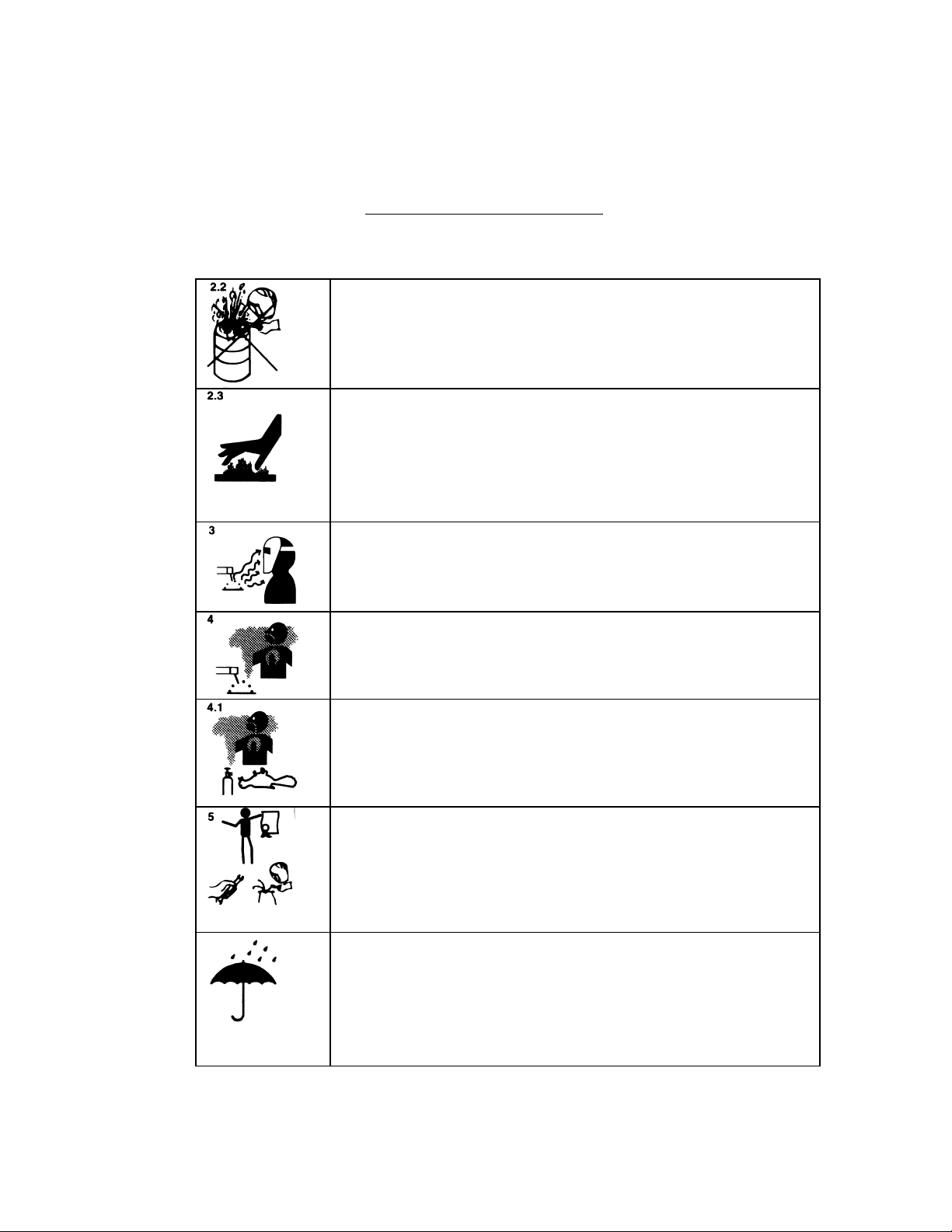
WARNING: Never weld on sealed containers or pipes. This
may result in an EXPLOSION.
WARNING: Welding produces high temperatures in both the
welded components and the welding equipment. Both can
soon after use. Avoid touching torch components and welding
fixtures soon after welding.
WARNING: The welding arc emits ultra-violet (UV) radiation
and the molten weld gives off infra-red. Both can burn eyes
and skin if unprotected. Suitable eye and skin protection must
Avoid touching internal components of the welding system
be worn.
WARNING: Weld materials can emit toxic fumes during
welding. WELD ONLY IN AREAS WITH ADEQUATE
VENTILATION.
WARNING: Most GTAW gases like Argon are non-toxic,
however, Argon is heavier than air and will displace the
normal atmosphere in enclosed areas. DO NOT WELD IN
ENCLOSED AREAS WITH OUT PROPER VENTILATION OR
RESPIRATORS.
WARNING: AMI factory training is essential for all Welding
Operators and Maintenance Technicians who operate AMI
equipment.
WARNING: Some systems, are intended solely for in-door
use and must be kept dry.
Before operating, storing or handling, always make sure that
the M-207A, M-207-RP Pendant, weld heads and cables are
not exposed to rain or standing water. SYSTEM
COMPONENTS ARE NOT WEATHER-PROOF.
1.3
Doc. No. 740044
Rev F
MODEL 207A AND 207A-1
OPERATION MANUAL
SECTION I - INTRODUCTION
1.1 SAFETY PRECAUTIONS
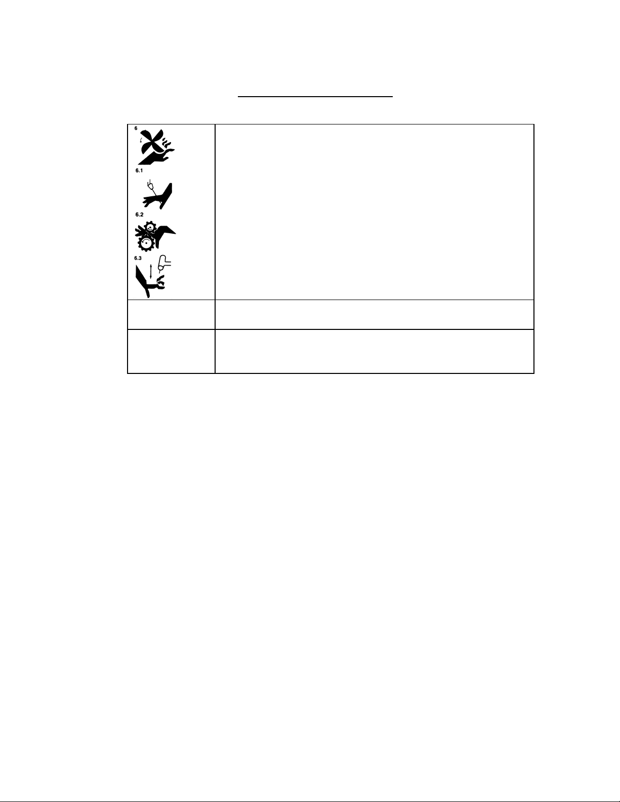
WARNING: Keep hands and fingers clear from moving parts
such as fans, gears rotors, Wire Feed, Rotation and AVC
Mechanisms.
WARNING: The M-207A Power Supply is not intended for
pipe thawing or heating in any form.
WARNING: The M-207A weighs in excess of 75 lbs. Be sure
to follow local, OSHA, International or employers guidelines
for proper methods of lifting and re-locating this equipment.
1.2 OPERATIONAL PRECAUTIONS
The following is a check list for operating personnel to follow to insure minimum
system down-time due to improper operation and handling:
1. TOO AVOID severe equipment damage VERIFY that the M-207A is
connected to the correct Input AC power (see section 3.1).
2. Before operating, check all fittings and connectors for proper seating and that
all protective boots are in place. If not properly seated or protected, short
circuits, poor connections or inert gas leaks could occur.
3. The M-207A is intended for typical GTAW gases ONLY. NEVER CONNECT
OXYGEN OR ACETYLENE TO THE M-207A.
4. Before operating, insure that all cables are routed or protected in such a way
that they will not be subject to heat, equipment and/or personnel traffic. Insure
that the cables DO NOT come in contact with HOT PIPE.
5. When storing or handling cables, always keep the protective boots and dust
caps on all connectors and fittings until ready to install. A major cause of
downtime in any automatic welding system is improper care and use of cables.
1.5
Doc. No. 740044
Rev F

MODEL 207A AND 207A-1
OPERATION MANUAL
SECTION I - INTRODUCTION
1.2 OPERATIONAL PRECAUTIONS
6. Before operating, insure that the M-207 has adequate air flow. Do not restrict
the intakes or exhaust vents of the power supply.
7. Before operating, always insure that there is bare metal contact between the
weld head components which connect to GROUND (clamp inserts, etc.) and
the tube or pipe to be welded.
8. When storing or handling weld heads, always keep them in the protective
containers they are shipped in, or optional carrying case, until ready to install.
9. When operating, storing or handling, insure that the system is protected
against dirt, dust, etc. NEVER GRIND NEAR AN EXPOSED WELD HEAD
OR THE M-207A.
10. Do not use acid, corrosives, liquid “Easy Out” or any liquid substance on the
M- 207A or any AMI weld head. When cleaning, use only a light solution of
Isopropyl alcohol on a soft cloth .
11. When handling, take extreme care to avoid dropping the M-207A, weld heads,
cables or any accessories.
12. Do not attempt to move tube end into position using the weld head as a lever.
13. Do not add any lubrication like graphite, oil or grease to the weld heads or
power supply unless it is specified in the operation or maintenance manual
for that equipment.
1.6
Doc. No. 740044
Rev F

MODEL 207A AND 207A-1
OPERATION MANUAL
SECTION I - INTRODUCTION
1.3 SHOCK HAZARD WARNING
As already stated in this manual “High Voltage” is present on exposed internal
terminals. The ELECTRODE (tungsten and M-9 rotors) is also an “exposed
terminal” and by its nature the GTAW process requires electrical potential to be
present on the electrode during arc starting and of course during the welding.
All AMI Power Supplies contain a “bleeder” circuit to ground any residual
potential after welding or after an aborted or bad “arc start” attempt. However,
these circuits take a few seconds to operate or COULD FAIL.
“THE ELECTRODE SHOULD ALWAYS BE CONSIDERED A POSSIBLE
SHOCK HAZARD”. This is especially true when ever the system is in “weld
sequence” ready to weld, is welding or has just finished welding. However,
equipment/component failure, system abuse, or improper maintenance could
result in electrical potential at the weld head “even when not in weld sequence”.
The users/operators of this equipment must take all precautions necessary to avoid
contact with the ELECTRODE at “ALL TIMES”. The only exception is when
actually replacing or adjusting the electrode and this should be done “WITH THE
POWER TURNED OFF”.
If performed with the power “ON” the system must be in test mode out of weld
sequence and the USER MUST OBSERVE COMMON SAFETY PRACTICES
such as grounding the electrode to insure discharge before actually touching it.
REMEMBER, there is a “POSSIBLE” shock hazard in all welding power supplies
at “ALL” times.
Most AMI Power Supplies feature High Frequency (HF) Arc Starting. This is a
High Voltage/High Frequency electrical transmission process. To eliminate any
HF shock possibility “AVOID ALL CONTACT” with the Welding WORK
(ground), the ELECTRODE or the WELD HEAD during arc start.
1.7
Doc. No. 740044
Rev F
MODEL 207A AND 207A-1
S
OPERATION MANUAL
SECTION II - SPECIFICATIONS
The following contains only general specifications about the M-207A Power
Supply. More detailed information is available in AMI Specification No. 207.
2.0 ELECTRICAL
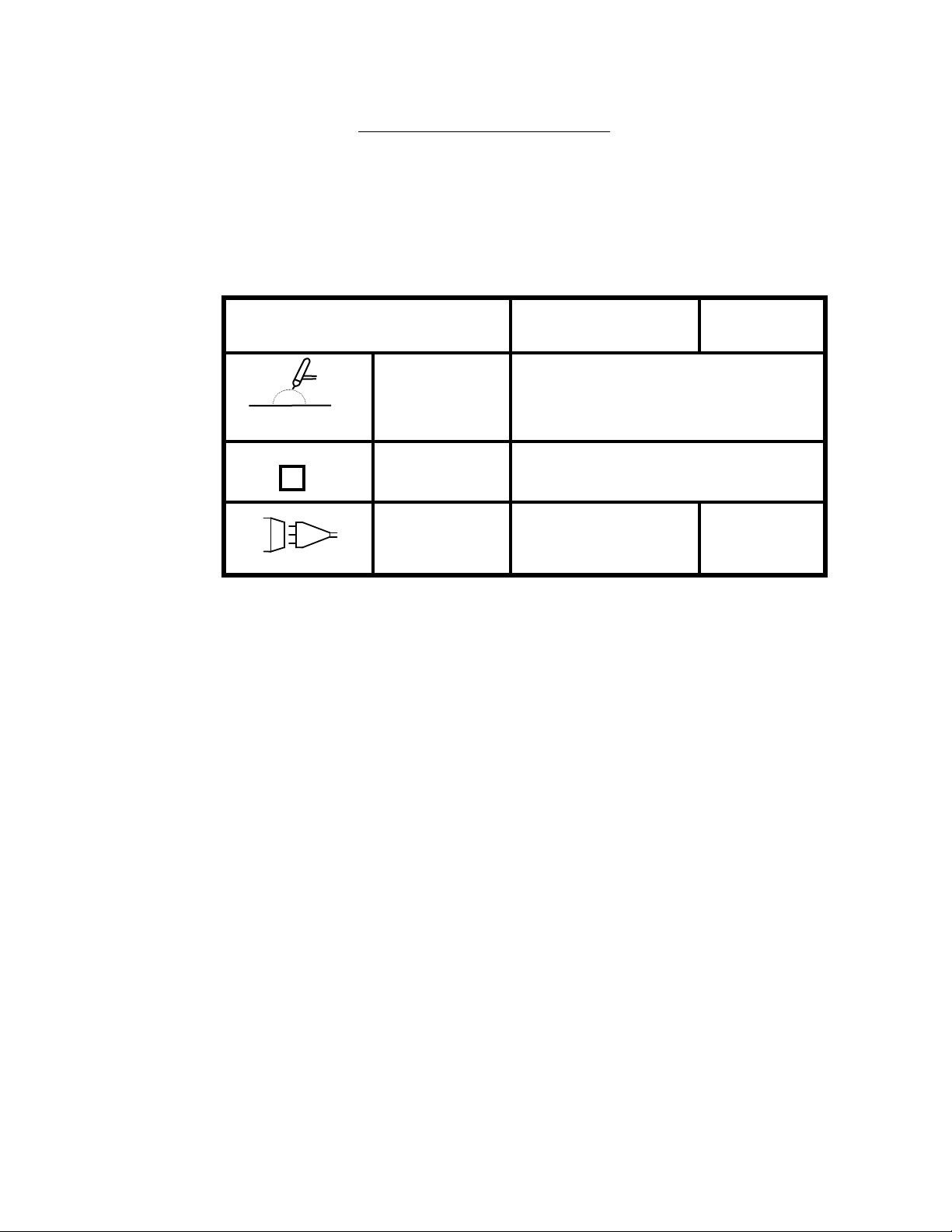
1. RATING PLATE DEFINITIONS
1) Company: Country:
ARC MACHINES, INC. USA
8) Process:
G.T.A.W
10) Type:
___________
_ _ _ _ _ _ _ _ _ _
DC
23) Shock Rating:
15) Input:
1~ 50/60 HZ
11) No-load Voltage:
U
= 59V
0
18) Voltage:
U
= 110V
1
220V
1) - Manufacturer and Country of Origin
3) - Model Number Rating Plate applies to.
4) - Serial Number (located on M-207A Center Plate, not on rating plate).
6) - International and USA Standards that the equipment meets.
8) - Weld Process symbol for GTAW welding.
9) - Rated minimum output amperes and output voltage (same all models).
Rated maximum output amperes and output voltage. M-207A maximum
rated current is 150 amperes at 20 volts and M-207A-1 are
limited to rated maximum of 100 amperes at 20 volts. All Models are
limited to 100 Amperes while connected to 110 VAC.
10) - Symbol that output is Direct Current (DC) only.
11) - Rated No Load Output Voltage (open circuit voltage) is 59 volts for
M-207A 79 volts for M-207A-1.
. 12) - All M-207A models are 100 % Duty Cycle for their rated outputs (9).
15) - Input Voltage type contains symbol for single (1) phase Alternating
Current (AC) input at 50 or 60 Hz frequency.
18) - Nominal Input Voltage value is 110 VAC or 220 VAC
19) - Rated maximum required supply current. Given for both I1 maximum
(I1max) and I1 effective (I1eff). Both are rated at 30 Ampere service for
110 VAC operation and 20 ampere service for 220 VAC operation.
2.1
3) Model:
Model 207A
9) Output:
Minimum Maximum
6) Standards:
NEMA EW1
IEC 974-1
3A / 5V 150A / 20V
12) Duty Cycle:
X = 100% ALL RATED OUTPUTS
19) Input Current:
I
1max
= 30A I
1eff
= 30A
20A 20A
21/22) Rating/Class:
IP21
Doc. No. 740044
Rev F

MODEL 207A AND 207A-1
OPERATION MANUAL
SECTION II - SPECIFICATIONS
2.0 ELECTRICAL
1. RATING PLATE DEFINITIONS
21) - International Protection (IP) rating. M-207A and M-207A-1 are rated
IP21 which includes protection against a limited amount of exposure to
rain (does not make it weather proof or intended for all weather usage).
.
22) - All M-207A models are class I. No symbol is used for class I
equipment.
23) - “S” Symbol indicates a welding power source which is suitable for an
environment with an increased electric shock hazard.
2. INPUT POWER, DETAIL - All M-207A Models, as shipped standard, can
operate on the following Single Phase input AC:
Voltage Tolerance Freq. Max Input Current
100 VAC + 32%, -10% 50/60 Hz 30 amperes
110 VAC + 20%, -18% 50/60 Hz 30 amperes
115 VAC + 15%, -22% 50/60 Hz 30 amperes
120 VAC + 10%, -25% 50/60 Hz 30 amperes
200 VAC + 32%, -10% 50/60 Hz 20 amperes
208 VAC + 27%, -13% 50/60 Hz 20 amperes
220 VAC + 20%, -18% 50/60 Hz 20 amperes
230 VAC +15%, -22% 50/60 Hz 20 amperes
240 VAC + 10%, -25% 50/60 Hz 20 amperes
+/- % indicates the allowable input voltage change to maintain performance as
specified. Maximum input current is based on maximum output current at
maximum arc voltage. See section 3.1 for installation.
3. OUTPUT POWER - Straight polarity, constant current DC regulation intended
for GTAW welding only. Static characteristic of all power supplies is flat.
All Models ................... = 3 to 100 amperes DC using 100 to 120 VAC input.
M-207A-1 = 3 to 100 amperes DC using 200 to 240 VAC input.
M207A ......................... = 3 to 150 amperes DC using 200 to 240 VAC input.
2.2
Doc. No. 740044
Rev F

MODEL 207A AND 207A-1
OPERATION MANUAL
SECTION II - SPECIFICATIONS
2.0 ELECTRICAL
4. CIRCUIT BREAKER - ON/OFF, two pole, 30 Ampere at 250 VAC.
2.1 PHYSICAL CONSTRUCTION - (power supply only)
Cabinet material - aluminum
Height - 10.9 in (276.9 mm) cover closed
- 9.3 in (236.2 mm) cover removed
Width - 22.75 in (577.9 mm)
Depth - 19.25 in (489.0 mm) including handle
Weight - 78 lbs (35.4 kg) (M-207A and M-207A-1)
2.2 PROGRAMMABLE and OPERATIONAL FUNCTIONS
PREPURGE TIME ............................................... = 010 - 999 seconds
POSTPURGE TIME ........................................... = 000 - 999 seconds
UPSLOPE TIME .................................................. = 00.0 - 99.9 seconds
DOWNSLOPE TIME .......................................... = 00.0 - 99.9 seconds
ROTATION START DELAY ............................. = 00.0 - 99.9 seconds
ROTATION MODE SETTINGS ........................ = CONT - STEP - OFF
PRIMARY ROTATION SPEED ........................ = 0.00 - 20.0 RPM
BACKGROUND ROTATION SPEED .............. = 0.00 - 20.0 RPM
PULSE MODE SETTINGS ................................ = ON - OFF
PRIMARY PULSE TIME ................................... = 0.00 - 9.99 seconds
BACKGROUND PULSE TIME .......................... = 0.00 - 9.99 seconds
LEVELS .............................................................. = 1 - 99
LEVEL TIME (each level) ................................... = 000 - 999 seconds*
PRIMARY CURRENT ........................................ = 3 - 150 amperes*
BACKGROUND CURRENT .............................. = 3 - 150 amperes*
* = Can be in increments of 0.1
2.3 MULTI-LEVEL FUNCTIONS - The following functions can be programmed to
change value during a given weld sequence.
FUNCTION POSSIBLE CHANGES
LEVEL TIME ...................................................... = 1 to 99 levels
2.3
Doc. No. 740044
Rev F

MODEL 207A AND 207A-1
OPERATION MANUAL
SECTION II - SPECIFICATIONS
2.3 MULTI-LEVEL FUNCTIONS (continued)
FUNCTION POSSIBLE CHANGES
PRIMARY CURRENT.............................................. = 1 to 99 levels
BACKGROUND CURRENT.................................... = 1 to 99 levels
PRIMARY PULSE TIME.......................................... = 1 to 99 levels
BACKGROUND PULSE TIME................................ = 1 to 99 levels
PULSE MODE (ON/OFF)......................................... = 1 to 99 levels
PRIMARY ROTATION............................................ = 1 to 99 levels
BACKGROUND ROTATION RPM......................... = 1 to 99 levels
ROTATION MODE (CONT/STEP/OFF)................. = 1 to 99 levels
2.4 AMBIENT TEMPERATURE RANGE - 32 F (0 C) to 110 F (45 C).
2.5 CABLE OPERATING DISTANCE LIMITS - Standard = 25’ (7.6 m)
Maximum = 100’ (30.5 m)
The standard distance consists of a 15’ adapter cable and a 10’ weld head cable
combined together. The maximum distance is achieved by adding extension
cables to the standard cables.
The above are considered normal limits. With special options, distances of 500
feet or more can be achieved. Consult an AMI representative for more
information.
2.4
Doc. No. 740044
Rev F
MODEL 207A AND 207A-1
OPERATION MANUAL
SECTION III - INSTALLATION
3.0 INSPECTION
1. After unpacking, inspect all items for obvious physical damage and loose
parts. If damage is evident, contact a factory representative before using.
NOTE
If water condensation is apparent, dry the unit before using.
2. All M-207A models are shipped with a variety of peripheral equipment such as
gas hoses, fittings, manuals (including this one) and electrical drawings. An
exact list of these items is included with each power supply shipment. This
manual will reference some of those items so before beginning installation
these items should be located and be available.
3.1 POWER CONNECTION
WARNING
Do not connect the M-207A power supply to any AC power other than the ones
listed in section 2.0.2.
The M-207A can operate on 9 different input line voltages and must be set up for
the one you are using. Use the following procedure to insure that the M-207A is
set-up for the correct AC power.
1. The M-207A is supplied with a 25’ power cord. One end has a connector on it
that plugs into the side of the M-207A. The wires on the other end are pig-
tailed (no connector). A suitable AC line connector, matching the input
power, must be supplied and installed by the user. Color coding of the
power cord is as follows:
Black ................. = Hot (high line side)
White ................. = Neutral (low line side)
Green/Yellow .... = Ground (protective earth ground)
NOTE
For additional ground reference there is a ground symbol silk-screened next to
the ground pin on the M-207A Input AC connector on the Input Panel.
3.1
Doc. No. 740044
Rev F

MODEL 207A AND 207A-1
OPERATION MANUAL
SECTION III - INSTALLATION
3.1 POWER CONNECTION
2. Install the AC line connector onto the power cord.
NOTE
DO NOT PLUG THE M- 207A INTO THE AC POWER SOURCE UNTIL
ALL INSTALLATION STEPS ARE COMPLETE.
3. Insure that the circuit breaker (CB-1) is in the down or OFF position (see
figure 2 and 3).
4. Using figure 2 and 3 as a reference, locate the power SELECT SWITCH
(next to the input power connector). The switch is concealed by a cover
plate and only the top of the switch handle can be seen through a hole in the
plate. The plate is labeled as to what voltage the switch is currently set for.
5. If the M-207A is to be run on 100, 110, 115 or 120 VAC this switch must be
in the 110 VAC position. If it is to be run on 200, 208, 220, 230 or 240
VAC it must be in the 220 VAC position. If it is in the correct position,
proceed to step 3.2.
6. To change the power select switch position, remove the cover retaining
screws (see figure 3) and remove the cover. Set the switch to the alternate
position and install the cover plate. It must be flipped over so the hole in the
plate will fit over the switch handle in the new position. This will
automatically expose the alternate voltage label on the other side.
3.2 WELDING GAS CONNECTIONS
NOTE
The following instructions are for M-207A
1. Three gas hoses are supplied with M-207A. These hoses are made of
material selected specifically for automatic welding. HOSES MADE FROM
OTHER MATERIAL ARE NOT RECOMMENDED (especially rubber,
nylon or tygon).
2. One 10 foot (3m) hose should be installed from the gas regulator/flowmeter
(user supplied) to the ARC GAS INPUT fitting on the M-207A. This hose is
supplied with all fittings required to mate with the M-207A and most domestic
(USA) inert gas flow meters.
3.2
Doc. No. 740044
Rev F

MODEL 207A AND 207A-1
OPERATION MANUAL
SECTION III - INSTALLATION
3.2 WELDING GAS CONNECTIONS
2. (continued)
NOTE
The arc gas line is controlled by a solenoid and flow sensor in the M-207A
and MUST BE connected to the M-207A (not directly to the weld head or
torch).
After installing the hose and fittings loosely by hand, tighten the retaining
nuts slightly with a wrench to insure there are no leaks, but do not over tighten. The use of plumbers tape or grease is not recommended.
CAUTION
The M-207A arc gas solenoid valve is rated at 50 PSI (345 KPa) maximum
pressure, DO NOT EXCEED THIS RATING.
3. The other 10’ (3 m) hose is intended for I.D. PURGE GAS INPUT and its
connection to and through the M-207A is optional. It is supplied with fittings
to connect from the gas source regulator/flowmeter to the PURGE GAS
input bulkhead fitting on the M-207A.
The M-207A does not supply a solenoid for control of I.D. PURGE GAS.
The line feeds straight through to the output quick-disconnect. If the output
hose is plugged in, gas will flow at all times. This feature is best for bench type weld development but not normally used for field I.D. purging of long
lengths of tube.
If you wish to use this option, install the hose and fittings loosely by hand,
tighten the retaining nuts slightly with a wrench to insure there are no leaks,
but do not over-tighten. The use of plumbers tape or grease is not
recommended (see figure 4).
4. The 25 foot (7.6 m) hose is intended to supply the I.D. purge from the M 207A to the weld. One end has a quick-disconnect on it that mates with the
PURGE GAS output bulkhead fitting on the M-207A. If used, the quick-
disconnect provides a convenient method for starting or stopping the flow of
I.D. purge gas. If you wish to use this option, insert the male quick-
disconnect of the hose into the M-207A connector labeled PURGE OUTPUT
(see Figure 2 and 4).
3.6
Doc. No. 740044
Rev F
MODEL 207A AND 207A-1
OPERATION MANUAL
SECTION III - INSTALLATION
3.3 ADAPTER CABLE TO M-207A INSTALLATION
NOTE
Although the Adapter Cable is used with most M-9 weld heads, some do not use it
(such as the M9-500). Consult your weld head manual for more details.
WARNING
Always turn the power supply off before making any cable or connection
changes to the M-207A power supply.
1. One end of the adapter cable ALWAYS connects to the weld head. The
other end connects to the M-207A or to a weld head extension cable. The
connector types and keyways are different for each item (except gas).
Use the following steps for connection to the M-207A (see figure 2 and 4).
2. Connect the GROUND and ELECTRODE connectors to their respective
terminals on the M-207A. Align the keyways, push in and twist clockwise
until fully locked.
3. Weld head CONTROL connector - Just before installing, unscrew the dust
caps on the cable and M-207A connector labeled WELD HEAD CONTROL.
Insert the cable connector into the M-207A panel connector. Note the
positioning keyway and NEVER FORCE or use tools on the cable
connections. Hand tighten the connecting ring after the pins are firmly seated.
4. Insert the cable male gas quick-disconnect into the M-207A ARC GAS
OUTPUT connector. Do not insert it in the purge gas output connector.
5. If the M227/207-CW or M207-CW optional cooling unit is being used, insert
the two coolant quick-disconnects into the COOLANT IN and COOLANT
OUT connectors on the CW. The cable coolant connectors are interchangeable
and it does not matter which one goes to in or out. See section 8.1 for CW
installation instructions.
3.4 WELD HEAD INSTALLATION - The weld head cable connects to the adapter
cable. Refer to figure 2 and 4 as you perform this installation.
NOTE
Although the Adapter Cable is used with most M-9 weld heads, some do not use it
(such as the M9-500). Consult your weld head manual for more details.
3.7
Doc. No. 740044
Rev F

MODEL 207A AND 207A-1
OPERATION MANUAL
SECTION III - INSTALLATION
3.4 WELD HEAD INSTALLATION (continued)
1. Insert the adapter cable GROUND, ELECTRODE AND GAS connectors
into the mating weld head cable connectors.
2. After the ELECTRODE, GROUND and GAS connectors are secure and
checked, slide the rubber boots on each line together and secure them in
place. These boots provide both a safety factor to prevent shorting to
ground and also act as a retainer to prevent the connectors from coming
apart.
3. Unscrew the CONTROL connector dust caps on both cables just before
installing. Insert the adapter connector into the head connector. Note the
positioning keyway and NEVER FORCE or use tools on the cable
connections. Using just your hand, tighten the connecting ring until the pins
are firmly seated. Screw the two dust caps together to prevent them form
swinging around.
4. Installation is now complete.
CAUTION
Before proceeding with POWER ON it is EXTREMELY important to have a
basic understanding of SYSTEM FUNCTIONS. Read section IV (system
functions) before proceeding with OPERATION (section V) or
PROGRAMMING (section VI).
3.8
Doc. No. 740044
Rev F

MODEL 207A AND 207A-1
OPERATION MANUAL
SECTION IV - SYSTEM FUNCTIONS
4.0 INTRODUCTION
The M-207A is intended for use with AMI orbital welding heads and has functions
designed for these weld heads. This section describes what these functions are
and may, where needed for clarification, indicate how they are commonly (but not
always) used.
Step 4.1 is general description; the remaining steps describe, in more detail, the
items of steps 4.1. Only FUNCTION is discussed here. Details of function
ranges and tolerances can be found in section II of this manual and in AMI
Specification No. 207. Details about operating these functions can be found in
section V.
4.1 FUNCTIONAL DESCRIPTION, GENERAL
1. LIBRARY - The heart of the M-207A is its MEMORY. The values of each
function , for a given weld, are only programmed one time. After that the
M-207A will store the function values (for that weld) by WELD
SCHEDULE NUMBER (#) and description.
When a particular weld type is needed to be made the Operator can locate it
in the WELD SCHEDULE LIBRARY by description or by weld schedule
number (#).
2. WELD SEQUENCE AND LEVELS - Selected weld schedules are started
by manually initiating the SEQUENCE START. Once the sequence is
started the system operation of functions is totally automatic.
In addition to functions to start and stop the weld, the weld sequence
includes the ability to preset changes in function values and modes. These
changes are called LEVELS and as many as 100 levels can be used for each
weld sequence. All weld schedules start with (and must have) Level 1.
If preset changes are desired they will be set in LEVELS 2, 3, etc. The
LEVELS advance from 1 to 2, 2 to 3, etc. automatically as a function of
time.
3. CURRENT SOURCE AND CONTROL - The M-207A is a pulsed, 150
ampere, constant current, straight polarity, GTAW power source. The
current value(s) can be set between 3 and 150 Amps
4.1
Doc. No. 740044
Rev F

MODEL 207A AND 207A-1
OPERATION MANUAL
SECTION IV - SYSTEM FUNCTIONS
4.1 FUNCTIONAL DESCRIPTION, GENERAL
4. TRAVEL FUNCTION - The system is equipped with a motor servo
controller that provides the power and regulation for rotating the arc around
the weld seam. The system controls the movement in revolutions per
minute (RPM).
NOTE
The motor servo can only work properly if the weld head being used is
equipped with a motor assembly designed for operation on the M-207A.
5. PULSATION - The system can rapidly change or PULSE back and forth
between two (2) different values of CURRENT and two different values of
TRAVEL. The normal or HIGH value is designated the PRIMARY value.
The other or LOW value is designated the BACKGROUND value.
This pulsation is done as a function of time by using the PRIMARY and
BACKGROUND PULSE TIMES to set an exact amount of time for each
PRIMARY and BACKGROUND function to occur.
6. OVERRIDES - The weld schedule programmer can set the M-207A to allow
the operator to change the value of some weld schedule functions. The
programmer can also set limits to the amount of changes the operator can
make to each function.
7. FAULT STATUS - The system continuously monitors certain functions
such as gas flow, coolant flow (if used), system temperature and input AC.
If there are any problems the system will alert the operator and in some
cases, where weld quality might be affected, the system will stop the
welding process.
8. GAS FUNCTIONS - As stated, the M-207A is intended for the GTAW
process. This process requires a welding gas (usually inert) for operation,
and the M-207A is equipped with a gas solenoid and input/output connectors
for the control of the welding (arc) gas.
9. PRINT FUNCTIONS - Built into the M-207A is a thermal Printer. The
printer allows copies of the Library and complete weld schedule to be made.
4.2
Doc. No. 740044
Rev F

MODEL 207A AND 207A-1
OPERATION MANUAL
SECTION IV - SYSTEM FUNCTIONS
4.2 WELD LIBRARY AND WELD DESCRIPTION
Each weld schedule programmed into the system memory is identified and
displayed (when selected) with the following information:
1. # = Individual WELD SCHEDULE NUMBER from 001 to 100.
2. OD = Outside diameter in inches or mm of the weld.
3. WALL = Wall thickness in inches or mm of the weld.
4. TYPE = Uses abbreviations to identify the type of weld the schedule is for
(see section 4.9 for list).
5. MAT = Uses abbreviations to identify the base material the schedule is for
(see section 4.9 for list).
6. QTY = Indicates the number of times this weld schedule has been used since
last reset.
4.3 WELD SEQUENCE - Although the M-207A can be used as a manual welding
power source, it is primarily intended to follow an automatic SEQUENCE.
After a weld schedule is selected and the weld is setup, the SEQUENCE will be
manually started by the operator and the following events will occur automatically
(see figure 5 for the timing chart):
1. EVENT 1: PREPURGE - Welding gas will start to flow (for the entire weld)
from the gas source (user supplied) through the power supply to the weld
head. Complete gas coverage should be obtained before the arc is struck.
How long it flows before the arc is struck is called the PREPURGE TIME.
Minimum programmable time is 10 seconds.
2. EVENT 2: ARC START - When PREPURGE time is complete a high
frequency pulse will be generated to establish an arc between the electrode
and the weld joint.
3. EVENT 3: LEVEL 1 TIME, START LEVEL, UPSLOPE, TRAVEL START
DELAY - When the arc starts the following functions all start at the same time:
1. LEVEL 1 TIME - When the arc is established all weld functions are
considered to be in LEVEL 1. The LEVEL 1 Timer will start to count
and the M-207A will stay in LEVEL 1 until this time is complete.
2. WELD CURRENT START LEVEL - As the arc is established the
weld current will jump to a small value. This current is used to stabilize
the arc and is called the START LEVEL. Its value is adjustable and
may need to be changed depending on certain conditions.
4.3
Doc. No. 740044
Rev F

MODEL 207A AND 207A-1
OPERATION MANUAL
SECTION IV - SYSTEM FUNCTIONS
4.3 WELD SEQUENCE
3. EVENT 3: LEVEL 1 TIME, START LEVEL, UPSLOPE, TRAVEL.
START DELAY -
3. WELD CURRENT UPSLOPE - Sometimes it may be necessary to
raise the weld current to full value slowly. This is called UPSLOPE.
When the arc is established the weld current will start to rise to the
PRIMARY and BACKGROUND (if pulsed) value programmed in
LEVEL 1. The time it takes to rise to full value is the UPSLOPE
TIME.
4. PRIMARY and BACKGROUND PULSE TIMES - When the arc is
established and the LEVEL 1 PULSE MODE is programmed to the
ON position, the weld current will be pulsing between the PRIMARY
and BACKGROUND VALUES (it may be upsloping at first). The
amount of time it stays in the PRIMARY is set by the PRIMARY
PULSE TIME; it will be followed by the BACKGROUND PULSE
TIME, then the PRIMARY PULSE TIME and so on.
5. TRAVEL START DELAY - Rotation of the arc should not occur in
most cases until full penetration of the weld has been achieved. When
the arc is established the TRAVEL START DELAY time will begin to
count. When this programmable period of time is complete the weld
head will start to rotate the arc.
4. EVENT 4: FULL LEVEL FUNCTIONS - Sometime after the arc is
established, depending on the weld schedule, the UPSLOPE and TRAVEL
START DELAY will be completed and all of the following functions will
be in effect:
1. LEVEL 1 TIME - Will be counting towards 0. During its count all of
the below functions will be occurring:
2. LEVEL 1 PULSE MODE - Can be programmed to be ON or OFF. If
ON the system will pulse between PRIMARY and BACKGROUND
function values.
3. LEVEL 1 PRIMARY PULSE TIME - If the LEVEL 1 PULSE
MODE is ON this function will operate (see Event 3).
4.4
Doc. No. 740044
Rev F

MODEL 207A AND 207A-1
OPERATION MANUAL
SECTION IV - SYSTEM FUNCTIONS
4.3 WELD SEQUENCE
4. EVENT 4: FULL LEVEL FUNCTIONS -
4. LEVEL 1 BACKGROUND PULSE TIME - If the LEVEL 1 PULSE
MODE is ON this function will operate (see Event 3).
5. LEVEL 1 PRIMARY AMPS - After UPSLOPE the system will be
regulating this programmed value of current.
6. LEVEL 1 BACKGROUND AMPS - If the LEVEL PULSE MODE was
programmed to ON, the system will be pulsing between the PRIMARY
VALUE and the BACKGROUND VALUE.
7. LEVEL 1 TRAVEL MODE - After the TRAVEL START DELAY time
is complete the travel function will be allowed to operate in 1 of 3
programmable modes.
OFF = Will prevent rotation from occurring.
CONTINUOUS = Runs the travel at the PRIMARY-RPM speed
only, regardless of PULSE MODE.
STEP = Will pulse the travel between the PRIMARY RPM and BACKGROUND-RPM speed. If the
TRAVEL MODE is in STEP but the PULSE
MODE is in OFF them only PRIMARY will
occur (without pulsing there are no background
functions).
8. LEVEL 1 PRIMARY-RPMS - After the TRAVEL START DELAY
time is complete the travel function will begin. If the LEVEL 1
TRAVEL MODE is programmed to the CONTINUOUS mode the travel
will be rotating the arc at the PRIMARY-RPM rate. If the mode is in
STEP it will rotate the arc at the PRIMARY-RPM speed each time the
LEVEL 1 PRIMARY PULSE TIME occurs.
9. LEVEL 1 BACKGROUND-RPM - If the LEVEL 1 PULSE MODE is
ON and the TRAVEL MODE is in STEP the system will rotate the arc
at the BACKGROUND-RPM each time the LEVEL 1 BACKGROUND
PULSE TIME occurs.
4.5
Doc. No. 740044
Rev F

MODEL 207A AND 207A-1
OPERATION MANUAL
SECTION IV - SYSTEM FUNCTIONS
4.3 WELD SEQUENCE
4. EVENT 4: FULL LEVEL FUNCTIONS -
NOTE
Travel direction is programmable CLOCKWISE or COUNTER CLOCKWISE. After the TRAVEL START DELAY the arc will
rotate in the programmed direction. The direction is not programmable by
LEVELS. It will rotate the arc in the same direction for the entire WELD
SEQUENCE.
5. EVENT 5: LEVEL 2 TO LAST PROGRAMMED LEVEL - As the arc is
rotated around the weld it is usually necessary to program changes in the
current, pulse times, modes and rotation speed. These changes are called
LEVELS and up to 100 can be programmed for each sequence. Each
LEVEL contains the same functions and options as EVENT 4. Each
LEVEL TIME determines the duration of that level.
6. EVENT 6: DOWNSLOPE - When the last programmed LEVEL is
complete the WELD SEQUENCE will begin the process of stopping. To
avoid cratering and cracking of the weld the current needs to be reduced
slowly. The last LEVEL PRIMARY-AMP value and BACKGROUND AMP value (if pulsed)will start to decrease towards 0. This time is called
DOWNSLOPE and is programmable.
7. EVENT 7: POSTPURGE - At the end of DOWNSLOPE, when the current
is less than 3 amperes, the arc will go out. All functions except gas flow
will stop. The gas should not be stopped until the weld and electrode are
cooled enough to prevent oxidation. How long the gas continues to flow is
programmable and is called the POSTPURGE TIME.
8. EVENT 8: RETURN TO HOME AND RESET - When POSTPURGE is
complete the gas will shut off. The M-9 welding head rotor will usually not
be in the proper position for head removal from the weld. When the gas shuts
off the rotor will return to the open (home) position and the weld head
can be removed from the weld. The system will then reset and be ready to
make another weld sequence.
4.6
Doc. No. 740044
Rev F

MODEL 207A AND 207A-1
OPERATION MANUAL
SECTION IV - SYSTEM FUNCTIONS
4.4 PANEL KEYS - The following are descriptions of all active operating keys
contained on the system (see figure 6).
1. ALL STOP KEY - Active only during weld sequence in test or weld mode.
When pressed it will stop the sequence, turn off the arc with no downslope
and start the postpurge process (see 4.3 event 7).
2. C KEY - Used for screen clear or cancel, it usually will end (without
storing) the screen will prompt the operator to indicate what will happen if
the C key is pressed.
3. CE KEY - The clear entry key is used to clear numbers entered with the
numeric keys before the enter key is pressed. Use this key when a mistake
is make using the numeric keys.
4. ENTER KEY - Used at the end of each step to indicate completion and to
move to the next step or screen.
5. F KEY - These are function keys numbered 1 to 16. Each key is aligned
with a portion of the display and are used to activate, cycle or alter the item
displayed above or below it. Each key will alter different functions
depending on what screen is being displayed. Use of the F keys is always
prompted by the screens.
6. L KEY - The M-207 is multi-lingual. Pressing this key will change the
display from English to French or to German if pressed again or to Swedish
or to Japanese if continued to be pressed.. The L key is always active..
7. LIB KEY - Used to access the LIBRARY (weld schedule memory/storage).
8. MANUAL PURGE KEY - Active at all times. Used for manually turning
on the gas solenoid. When ON, the gas solenoid will be energized and it
will stay ON until this key is manually pressed again.
9. NEXT LEVEL KEY - Active when weld schedules with more than one
level are being displayed. An * will appear on the display to indicate that
more levels are programmed for that weld schedule.
10. NEXT SCREEN KEY - Active when another screen (more data) is available
for a weld schedule or function. An * will appear on the display to indicate
that more data is available on the next screen.
4.9
Doc. No. 740044
Rev F

MODEL 207A AND 207A-1
OPERATION MANUAL
SECTION IV - SYSTEM FUNCTIONS
4.4 PANEL KEYS
11. NUMERIC KEYS - Used to select weld schedule number (#) or to enter
numbers during programming, overriding and set-up functions.
12. PREV LEVEL KEY - Same as NEXT LEVEL but levels appear in reverse
order.
13. PREV SCREEN KEY - Same as NEXT SCREEN but screens appear in
reverse order.
14. PRINT KEY - Only works if the printer option is used. If pressed when the
status is displayed a copy of system hours and software revision will be
printed. If pressed during the library screen a copy of the entire library will
be printed. During a weld schedule screen a copy of that entire weld
schedule will be printed. The key will not be active at any other time. It
cannot be used during an actual weld sequence. The date will be printed on
every copy.
15. PRO KEY - Active only if the OPERATE MODE SWITCH is in the
PROGRAM position. Pressing the pro key from the status screen will
access the programming modes. During programming the PRO key is used
to store information.
16. SEQ START KEY - Active with the schedule screen. When pressed this
key will start the weld sequence (see 4.3).
17. SEQ STOP KEY - Active only during weld sequence screen. When pressed
this key will stop the weld sequence and start the downslope function (4.3
event 6).
18. SET UP KEY - Active at all times except during a weld sequence. When
pressed this key will allow access to various set-up options (see 4.8).
19. TVL CW JOG KEY - Active at all times. When pressed the electrode will
rotate clockwise.
20. TVL CCW JOG KEY - Active at all times. When pressed the weld head
will rotate the electrode in the counterclockwise direction.
4.10
Doc. No. 740044
Rev F

MODEL 207A AND 207A-1
OPERATION MANUAL
SECTION IV - SYSTEM FUNCTIONS
4.4 PANEL KEYS
21. WELD/TEST KEY - At power on the M-207A will always be in the TEST
mode. In TEST mode a weld sequence can be run but NO ARC will be
struck. The user must press this key to initiate WELD mode. Once this is
done the M-207A will stay in WELD mode as long as the same weld
schedule is displayed. Changing schedules will cause the system to return to
the TEST mode.
22. STOP PRINT KEY - This key will allow the user to stop the printing
process for any reason.
23. PAPER FEED KEY - This key allows the user to advance the paper in the
printer.
4.5 OPERATE MODE SWITCH
This is a three position switch with a locking key. When set to the desired
position (mode) the key can be removed to prevent any non-key holder from
changing the mode.
The OPERATE MODE SWITCH sets the M-207A to be run in any of three
separate modes as described below:
1. OPERATE/WELD SELECT POSITION - The OPERATE mode is for
standard welding operations. It allows access to all weld schedules and set up screens. All normal system operations, such as weld sequence, etc. are
performed in this mode. In this mode the operator CANNOT perform any
PROGRAMMING functions or changes to the memory such as creating,
modifying, transferring or deleting.
2. MODE LOCK - After a weld schedule has been selected it may be locked-in
to prevent selection of any other weld schedule. This feature is intended
primarily for when the operator is welding out-of-sight of the M-207A or if a
supervisor wishes to insure that ONLY a particular weld schedule is used.
3. PROGRAM/OPERATE - In order to CREATE, MODIFY, TRANSFER,
COPY or DELETE a weld schedule in the system memory, the mode switch
must be set to this position. All system operations, such as weld sequence,
can also be performed in this mode.
4.11
Doc. No. 740044
Rev F

MODEL 207A AND 207A-1
OPERATION MANUAL
SECTION IV - SYSTEM FUNCTIONS
4.5 OPERATE MODE SWITCH
CAUTION
Authorization and access to the OPERATE MODE KEY should be controlled.
When the switch is set to the PROGRAM mode the operator may permanently
MODIFY (change) or DELETE weld schedule information contained in the
system memory.
4.6 FAULTS
The M-207A has the ability to monitor certain functions. If they are not working
correctly a system fault (FLT) will alert the operator to the problem.
The following is a description of each type of fault (FLT):
1. TEMP FLT - Power supply internal TEMPERATURE IS TOO HIGH.
Creates an ALL STOP condition if the occurs during weld sequence.
2. COOL FLT - Insufficient TORCH COOLANT FLOW. Active only with
the CW option. Creates an ALL STOP condition if it occurs during
weld sequence.
3. LPVS FLT - Problems with the LOW VOLTAGE DC POWER SUPPLIES.
Create SEQ STOP if it occurs during weld sequence.
4. GAS FLT - TORCH GAS FLOW is not detected. Creates an ALL STOP if
it occurs during a weld.
5. INPUTAC FLT - The M-207A cannot achieve desired outputs because of
inadequate AC input. Creates a SEQ STOP if it occurs during a weld.
6. SENSOR 1,2,3 - User defined (see 4.7).
7. BAD START - Indicates that the system was unable to sustain an arc.
8. STUB OUT - If the Arc Voltage gets too low or the electrode should touch
the puddle then a stub out will occur.
9. HIGH VOLTS - If the Arc Voltage gets too high a fault will occur.
4.12
Doc. No. 740044
Rev F

MODEL 207A AND 207A-1
OPERATION MANUAL
SECTION IV - SYSTEM FUNCTIONS
4.6 FAULTS (continued)
The method of alerting the operator depends on what the fault is and when it
occurs. A problem with TEMP, LVPS or INPUTAC when the M-207A is first
turned on will create a FAULT SCREEN and the fault must be corrected before
the M-207A will proceed with any other functions.
A problem with COOL, GAS or SENSOR is common at power on or when
preparing for welding. These items will only create the FAULT SCREEN if they
occur during a weld sequence. BAD START appears only during weld sequence
(after pre-purge) and does not create a fault screen.
STUB OUT and HIGH VOLTS will only occur during a weld and will cause an
ALL STOP condition. After postpurge the normal “return to home” sequence will
also be disabled.
4.7 SENSOR 1, 2, 3 FAULTS
The M-207A has 3 separate inputs that the user can define for creating a fault
condition based on some external problem. The most common would be
connecting a gas analyzer (s) to the M-207A to detect excessive Oxygen in the
I.D. purge of a weld.
The user must make these connections and use the SET-UP screen (see 4.8) to
define what a fault is for this external input.
4.8 SET-UP FUNCTIONS
The following SET-UP functions provide some customizing and calculation
features to enhance system performance:
1. CALCULATE - Calculates TUNGSTEN LENGTH or performs IPM to
RPM conversions or calculates total LEVEL TIME required. All of these
calculations are used during weld procedure development.
2. WELD-SELECT - The optional REMOTE PENDANT may select up to 4
pre-determined weld schedules from memory. This function defines which
of the schedules may be selected.
4.13
Doc. No. 740044
Rev F

MODEL 207A AND 207A-1
OPERATION MANUAL
SECTION IV - SYSTEM FUNCTIONS
4.8 SET-UP FUNCTIONS
3. HEAD-CAL - Provides a method for calibrating a M-9 weld head to the
power supply.
4. REV - Used to display the SOFTWARE REVISION of an M-207A.
Depending on intended use, M-207A’s may have different software revisions.
5. PRINT EMM - Used to print a copy of the EMM memory.
6. ARC V FLT - Used to de-activate STUB OUT and HIGH VOLT faults.
These faults are usually needed to be turned off for manual welding, see
section 7.4.7.
7. AMP - TIME - Used to change the least significant digit of Level Current or
Level Time from whole numbers or tenths (000 or 000.0).
8. SENSORS - Used to activate and define external fault inputs.
9. QTY-RESET - Used to reset the quantity count for each weld schedule or
for the entire library.
10. START LEVEL - Used to set the value of INITIAL current used at arc
start.
11. DATE RESET - Used to reset DATE.
12. CANNED PROG - Used to LOCK or UNLOCK PROGRAM MODE for
canned programs in positions 71 to 100.
13. PRINTER - Used to select AUTO or MANUAL print mode.
14. WELD DATA RECORDING - Used to activate both entry of WELD ID#
before sequence and to activate recording weld information into a memory
card after each sequence.
15. OPERATOR ID/NAME - Used to enter the ID number or name of the
weld operator.
16. SERIAL NUMBER - Used to enter the M-207A Serial Number for Weld
Data Record feature.
4.14
Doc. No. 740044
Rev F

MODEL 207A AND 207A-1
OPERATION MANUAL
SECTION IV - SYSTEM FUNCTIONS
4.9 GLOSSARY OF DISPLAY SYMBOLS AND ABBREVIATIONS - The M-207A
displays contain many abbreviations. The following is an alphabetical listing
(symbols last) of most abbreviations.
AL = Aluminum
AMP = Amperage
AF = Automatic weld fitting
BCK = Background (low value of a function that pulses).
CAL = Calibrate or calibration
CCW = Counterclockwise - looking at M-9 from COVER SIDE.
CONT = Continuous (constant value, no pulsing)
COOL = Coolant flow
CS = Carbon steel
CW = Clockwise - looking at M-9 from COVER SIDE.
DLY = Delay time
EXT = External input or function
FLT = Fault
FTG = Fitting other than AF
HAS = Hastaloy
INC = Inconel
INPUTAC = In put power AC voltage check
IPM = Inches per minute
LIB = Library, listing of programmed weld schedules
LVL = Level or levels
LVPS = Low voltage DC power supply check
MAT = Material
MNL = Monel
OD = Outside diameter
OK = Means monitored function is operating properly.
PRE-PURGE-POST = Prepurge, postpurge columns.
PRI = Primary function value
PRI-AMP-BCK = Primary speed, background amp columns
PRI-PULSE-BCK = Primary time, background speed columns
PRI-RPM-BCK = Primary speed, background speed columns
PRO = Program mode
QTY = Quantity of weld made since last reset
QTY RESET = Select to reset weld quantity
REV = Software revision
ROT = Rotation or travel start delay time
4.15
Doc. No. 740044
Rev F

MODEL 207A AND 207A-1
OPERATION MANUAL
SECTION IV - SYSTEM FUNCTIONS
4.9 GLOSSARY (continued)
ROT DLY = Rotation or travel start delay time
RPM = Revolutions per minute
SKT = Socket type weld
SP = Special material and weld type.
SS = Stainless steel
SYS HOURS = System hours indicate total power-on time.
TEMP = Power supply internal temperature
TI = Titanium
T/TS = Tube to tubesheet
# = Weld schedule number
* = Indicates that more information is available
4.10 GLOSSARY OF DISPLAY TERMS - The M-207A displays contain many terms
that do not relate directly to a function or sequence. The following is a listing of
those terms:
AMIWELD = Name, type and revision of software
ARC GAP = Distance needed between electrode and weld
ARC HOURS = Total hours system has been welding
BAD START = Problem has occurred with RF start.
CALCULATE = Function calculates RPM or tungsten length.
CANCEL = Ends step without storing or completing
COPY = Allows a schedule to be copied with a new #.
CREATE = For creating a new weld schedule
DATE RESET = Resets date function
DELETE = Used to delete a weld schedule from memory
INVALID NUMBER = Can appear under the following conditions:
1. Attempting to CREATE a weld schedule that already
exists.
2. Selecting a weld schedule that does not exist.
MODE LOCK = Screen cannot be changed. Weld schedule (if selected)
will be locked in.
MODIFY = Used to permanently change a weld schedule.
OPERATE/WELD SELECT = Operate mode only, cannot program
OVERRIDES = Ability to change a value temporarily.
PROGRAM/OPERATE = Ability to program or operate.
RING = Insert ring is used for filler material.
4.16
Doc. No. 740044
Rev F

MODEL 207A AND 207A-1
OPERATION MANUAL
SECTION IV - SYSTEM FUNCTIONS
4.10 GLOSSARY OF DISPLAY TERMS (continued)
ROTOR OD = Outside diameter of M-9 rotor.
SENSOR 1, 2, 3 = User defined faults.
STORE = Puts weld information into memory.
TRANSFER = Allows copying of memory to another M-207A or to the
M-207-EMM.
TYPE = Describes the basic type of weld.
WALL = Wall thickness of the weld.
WARNING = Used to indicate that if step is continued a permanent loss
of information will result.
4.17
Doc. No. 740044
Rev F

MODEL 207A AND 207A-1
OPERATION MANUAL
SECTION V - OPERATION
5.0 INTRODUCTION
Operation covers those steps that must be taken to actually perform a weld.
Programming and development of schedules are not covered in this section.
It is very important to insure before operating, that the operator has INSTALLED
the M-207A per section III and has a good understanding of functions from
section IV. Function explanations are not covered in this section.
The M-207A uses two displays to provide information and instructions for use.
For the most part, the information and instructions presented on these displays are
adequate explanation of operation. This section is only intended as a guideline to
get started with, for first-time users, AFTER HAVING ATTENDED AN AMI
M-207A TRAINING CLASS.
5.1 INITIAL POWER ON/STATUS SCREEN
1. Before connecting or energizing the AC power; verify that all input power set
up requirements of step 3.1 have been complied with.
WARNING
Applying the wrong input AC voltage to an M-207A (for how it is set up)
CAN CAUSE THE INPUT VARISTORS TO FAIL. Before turning the
power ON MAKE SURE THE INPUT POWER SET UP IS CORRECT
FOR THE POWER BEING USED.
2. The M-207A can be turned on without the adapter cable, gas hoses or weld
head connected. However, to verify proper operation they must be connected.
Insure that all of these connections are made per steps 3.2, 3.3 and 3.4.
3. Plug in the AC power cable to the AC source. Move the circuit breaker (CB1)
to the ON position.
4. After a few seconds the STATUS SCREEN will appear as shown on the next
page:
5.1
Doc. No. 740044
Rev F

MODEL 207A AND 207A-1
OPERATION MANUAL
5.1 INITIAL POWER ON/STATUS SCREEN
4. (continued)
If the input power is too low it is possible for the screens not to turn on, or to
be scrambled or get a fault screen indicating a LVPS fault. If these conditions
occur recycle CB1. If they continue to occur check the input power and the
power setup of the M-207A
UPPER SCREEN
TO WELD PRESS LIB TO PROGRAM PRESS PRO
SYS HOURS - 00000.0 ARC HOURS - 00000.0
LOWER SCREEN
TEMP-OK INPUTAC-OK GAS-OK LVPS-OK
COOL-OK SENSOR 1-OK 2-OK 3-OK
Actual hours will appear where the above shows 0. COOL, GAS OR
SENSOR 1, 2, 3 may indicate FLT where OK appears. This is considered
normal at power-up.
5.2 USE OF NEXT/PREV SCREENS/LEVELS
Weld schedules contain more data than can be shown at one time. To display this
data the NEXT/PREV SCREEN keys and NEXT/PREV LEVEL keys must be
used. These keys are located at the corners of the lower display. When there is
more data on another screen or level, a flashing * will appear in the appropriate
corner (s) to indicate that more information is available.
Screen/Level keys are used in selection of a weld schedule and all weld schedules
use 4 basic screens that appear in the following order:
1. PROMPT SCREEN - Appears when a weld schedule is called up from
memory.
2. LEVEL 01 AMPS - TIME - PULSE = Displays the value of AMPS, LEVEL
TIME and PULSE TIMES for LEVEL 1.
3. LEVEL 01 RPM - MODES = Displays the value of ROTATION RPM,
PULSE MODE and TRAVEL MODE for LEVEL 1.
4. PURGE - SLOPE - ROT DELAY = Displays the time for PREPURGE,
POSTPURGE, UPSLOPE, DOWNSLOPE and ROTATION START
DELAY.
Pressing the NEXT SCREEN key will advance the display in the above order.
When viewing screen 2, 3 or 4 (above) pressing the PREV SCREEN key will
reverse the order.
Doc. No. 740044
Rev F
SECTION V - OPERATION
NOTE
5.2

MODEL 207A AND 207A-1
OPERATION MANUAL
SECTION V - OPERATION
5.2 USE OF NEXT/PREV SCREENS/LEVELS (continued)
The weld schedule can be programmed to have up to a 100 levels of screen 2 and
3. When viewing screen 2 or 3 the operator can press the NEXT LEVEL key to
view the values for the next level (if programmed). When displaying level 2 or
greater, pressing the PRE LEVEL key will then display the previous level.
Pressing the NEXT SCREEN or PREV SCREEN key after using the NEXT
LEVEL or PREV LEVEL key will display the next screen for that level, except if
the next screen is screen 1 or 4 above, these screens are the same for all levels.
Reference figure 7 for a flow chart on the use of NEXT/PREV SCREEN and
LEVEL keys.
5.3 WELD SCHEDULE SELECTION
The following describes how to select a weld schedule from the library. The
OPERATE MODE switch must be in the OPERATE or PROGRAM position. Be
sure to have read section 5.2, use of NEXT/PREV keys before proceeding.
1. Press the C key until the STATUS screen appears.
2. Press the LIB key and the following display will appear:
USE SCREEN KEYS TO FIND # PRESS ENTER
OR IF # IS KNOWN ENTER #--- PRESS ENTER
# OD WALL TYPE MAT QTY *
001 1.500 .065 TUBE SS 0010*
Instructions are displayed on the upper screen. The first weld schedule in
memory (may not be #001) will be displayed on the lower screen.
3. If you know what weld schedule you want, enter its number using the numeric
keys. The numbers will appear in the --- area as you enter them. If you make
a mistake press CE and start over. When you have entered and verified the
correct number press the ENTER key. After a few seconds your selected weld
schedule will appear on the display. Proceed to step 5 (below).
5.4
Doc. No. 740044
Rev F

MODEL 207A AND 207A-1
OPERATION MANUAL
SECTION V - OPERATION
5.3 WELD SCHEDULE SELECTION
4. To find the weld schedule you want press the NEXT SCREEN key. The next
weld schedule in memory will be displayed. Continue pressing the NEXT
SCREEN key until the desired weld schedule appears. When the desired
schedule appears, press the ENTER key. After a few seconds your selected
weld schedule will appear on the display.
5. When the weld schedule is called up from memory it will appear on the
screens like this:
# OD WALL TYPE MAT QTY READY
001 1.500 .065 TUBE SS 0010 TO TEST
USE NEST SCREEN FOR VALUES THEN F KEYS *
TO CHANGE VALUES - USE SEQ START TO WELD
READY TO TEST may say FAULT ______ with an explanation in the
_______ space as to what the fault is. The fault must be corrected before
proceeding.
5.4 VIEWING FUNCTION VALUES
NOTE
Insure that section 5.2, NEXT/PREV SCREEN/LEVEL has been
reviewed before proceeding.
1. Pressing the NEXT SCREEN key after the weld schedule has been selected
from the library will result in the following screen:
# OD WALL TYPE MAT QTY READY
001 1.500 .065 TUBE SS 0010 TO TEST
*LVL-TIME PRI--AMP--BCK PRI-PULSE-BCK*
01 000 000 000 0.00 0.00*
The above shows amperes, pulse times and level time (duration) for level 1 of
the schedule.
2. After reviewing this information the operator can do one of the following:
1. Make changes to these level 1 functions (see 5.5).
5.5
Doc. No. 740044
Rev F

MODEL 207A AND 207A-1
OPERATION MANUAL
SECTION V - OPERATION
5.4 VIEWING FUNCTION VALUES
2. (continued)
2. Press the NEXT LEVEL or NEXT SCREEN key to review the entire weld
schedule as depicted in figure 7 and make changes if desired (see 5.5).
3. Press the SEQ START key to run this weld sequence. (See 5.9
5.5 OVERRIDING FUNCTION VALUES, BEFORE SEQUENCE START
Each weld schedule in the M-207A library can be programmed to allow unlimited,
limited or NO changes to be made to the function values of the weld schedule. If
the weld schedule allows changes to be made use the following procedure.
1. Use the NEXT SCREEN and/or NEXT LEVEL keys until the function value
to be changed appears on the screen.
2. Directly above and below each function value is an F key. When either one is
pressed the first time, the function to be changed will start to blink.
3. When the function to be changed is blinking, the value can be changed two
ways. A small INCREASE in the value can be made by pressing the UPPER
F key. A DECREASE in the value can be made by pressing the LOWER F
key. Each time the F key is pressed the value will change by the smallest
programmable increment.
Large changes should be done using the numeric keys. With the function
blinking (step 2) enter the new value using the numeric key pad. Verify that
the new value appears on the display. If you make a mistake press the CE key
and try again.
4. When the new value is displayed and verified, press the ENTER key. The
function will stop blinking and the system is ready to change another value or
to operate.
5.6
Doc. No. 740044
Rev F

MODEL 207A AND 207A-1
OPERATION MANUAL
SECTION V - OPERATION
5.6 OVERRIDING FUNCTION VALUES, DURING WELD SEQUENCE
It is possible to over-ride the value of the following functions during Weld
Sequence:
Level Time Primary Amps Background Amps
Primary Pulse Time Background Pulse Time Primary RPM
Prepurge Time Post Purge Time Background RPM
Overrides during sequence can only be done by use of the F KEYS (see in 5.5.3).
The numeric keypad cannot be used.
You cannot override during weld sequence the Pulse Mode, Travel Step Mode,
Upslope Time, Downslope Time or Travel Direction.
5.7 SET UP FUNCTIONS
There are two types of SET UP screens. Both are accessed with the SET UP key.
One type appears when the SYSTEM MODE is set to OPERATE and both appear
when the SYSTEM MODE is set to PROGRAM.
The SET UP screens offer special functions that can ENHANCE or in some cases
CHANGE the way the M-207A operates. It is important for the user to
understand these features. Under some conditions, if not properly set,
undesirable performance can occur.
1. SET UP FUNCTIONS IN OPERATE MODE - Pressing the SET UP key on
the M-207A panel when on the STATUS SCREEN or WELD SCREEN with
the SYSTEM MODE set to OPERATE will access the first of two SET UP
screens that contain the following functions:
1. CALC - Pressing the F key under this choice will access a prompt screen
for either calculating Tungsten Length, converting IPM to RPM or
calculating total Level Time. Select which one you wish to perform and
follow the on screen instructions.
2. WELD SELECT - This feature is used to select up to 4 different weld
schedules to be accessible by the M-207-RP Option. See Section 8.2 for
more details.
Travel Start Delay
NOTE
5.7
Doc. No. 740044
Rev F

MODEL 207A AND 207A-1
OPERATION MANUAL
SECTION V - OPERATION
5.7 SET UP FUNCTIONS
1. SET UP FUNCTIONS IN OPERATE MODE
3. HEAD CAL - This feature is used to calibrate Travel (rotation) speed of
the Weld Heads and MUST BE USED ANY TIME A CHANGE OF
WELD HEADS IS MADE. See Section 5.7 for operation.
4. REV - Pressing the F key under this will show the current software
REVISION installed. This can be important when discussing problems
or features with an AMI representative.
NOTE
The following are on the second SET UP screen and are accessed by pressing
NEXT SCREEN from the first SET UP screen.
5. PRINT EMM - Pressing the F key under this choice will create a Print
out of the LIBRARY contained in M-207-EMM Option (EMM must be
installed, see 8.3).
6. AMP - TIME - This feature allows the user to change the programmable
increments of LEVEL AMPS or LEVEL TIME from 000 (whole
numbers) to 000.0 (tenths).
NOTE
This is not on an individual WELD # basis. All WELD # will be
changed automatically. If a WELD # was originally programmed for
87.7 amperes and this is changed to whole numbers the WELD # when
accessed will then call for 87 amperes (it will drop the digit, not round
off).
7. ARC V FAULT - This feature can turn this FAULT ON or OFF. When
ON a STUB OUT will be created if the ARC VOLTAGE goes below 5V
or a HIGH VOLTS fault if the VOLTAGE goes over 20 V. However, in
manual welding these conditions can occur without anything being
wrong. THIS FEATURE NEEDS TO BE SET TO OFF FOR
MANUAL WELDING.
NOTE
The following are on the third SET UP screen (in operate mode) and are
accessed by pressing NEXT SCREEN from the second SET UP screen.
5.8
Doc. No. 740044
Rev F

MODEL 207A AND 207A-1
OPERATION MANUAL
SECTION V - OPERATION
5.7 SET UP FUNCTIONS
1. SET UP FUNCTIONS IN OPERATE MODE
8. WELD DATA RECORDING (WDR) - Selecting this feature will access
another screen that will allow the user to turn on WDR and/or turn on
WELD ID recording.
From this screen WDR STORAGE can be selected as “NOT SAVED” or
“PCMCIA”. If “NOT SAVED” is selected then WDR is turned OFF and
operation is normal. If “PCMCIA” is selected then the system will request
a WELD ID be entered at the beginning of sequence and will record the
weld data into a PCMCIA card at the end of sequence. This PCMCIA
card can be used in conjunction with AMI OLP PC software to be used for
Weld Record Data keeping.
From the same screen WELD ID can be selected as “NOT PROMPTED”
or “PROMPTED”. It can be set to “PROMPTED” anytime. However,
if WDR STORAGE is set to PCMCIA then WELD ID automatically
defaults to “PROMPTED” and cannot be changed When set to prompted
it will require that the WELD ID be entered at the beginning of sequence.
This weld ID will be recorded in the PCMCIA card (if WDR is on) and
will appear on the Weld Schedule Print if printed at the end of sequence.
9. OPERATOR ID / NAME - This feature will allow the operator to enter his
ID number or name. If entered it will appear on the weld schedule print
out at the end of sequence (if printed) and it will be recorded by Weld
Data Recording onto a PCMCIA card if that feature is being used. Once
entered it will be remembered by the system as the operator until it is
cleared.
10. SERIAL NUMBER - This feature will allow the operator to enter the
Power Supply Serial number. If WDR is being used the Serial Number
information will be recorded in the PCMCIA card for use with OLP.
5.9
Doc. No. 740044
Rev F

MODEL 207A AND 207A-1
OPERATION MANUAL
SECTION V - OPERATION
5.7 SET UP FUNCTIONS
2. SET UP FUNCTIONS IN PROGRAM MODE - If the System Mode is set to
PROGRAM these additional functions can be shown after the first two SET
UP screens.
1. START LEVEL - Right after the arc is struck an initial current is used to
stabilize the arc. This is called START LEVEL and can be programmed
for a value from 5 to 100 amperes. The START LEVEL current is only
used for a very short period of time but can make the difference between
good starts and bad starts. Always set this value as high as possible yet
still make good repeatable welds without excess penetration at the start.
2. SENSORS - The M-207A FAULT detection system (see 7.4) has an
EXTERNAL input feature that allows the user to monitor up to 3 external
functions (such as an Oxygen Analyzer) and create a M-207A FAULT if
that external feature should fail.
Pressing the F key under this will allow the user to turn any or all of the 3
Sensors ON and select whether the FAULT should occur with a LOW
input signal or HIGH input signal. Reference AMI drawing 45B072514
for pin connections and electrical signal information about High and Low.
3. PRINTER MODE - The M-207A can be set up to make a print out of the
Weld # automatically (AUTO) after every Sequence. If set to MANUAL a
print will only be made if the PRINT key is pressed after a weld sequence.
NOTE
The following SET UP functions are accessed, in PROGRAM MODE, by
pressing the NEXT SCREEN key from the third SET UP screen.
Remember they do not appear if the system mode is in OPERATE.
4. CANNED PROGRAMS - WELD #’S 71 to 100 can be LOCKED or
UNLOCKED. If LOCKED they cannot be MODIFIED, DELETED or
have new ones CREATED (even in the program mode). Even if
LOCKED they can still be copied to any available # between 1 and 70.
If UNLOCKED positions 71 to 100 become accessible to anyone with a
key for the MODE switch.
They are called CANNED programs because AMI ships the M-207A with
a few common weld procedures in these positions.
5.10
Doc. No. 740044
Rev F

MODEL 207A AND 207A-1
OPERATION MANUAL
SECTION V - OPERATION
5.7 SET UP FUNCTIONS
2. SET UP FUNCTIONS IN PROGRAM MODE
5. DATE RESET - Prints contain the DATE of print. The DATE can be
RESET by using this feature.
6. QTY - RESET - The M-207A keeps count of how many times an
individual WELD # is successfully run. It also TOTALS this count for the
entire LIBRARY. This information can be viewed on the LIBRARY
Screen and is also printed when a PRINT of the LIBRARY or individual
WELD # is made.
Pressing the F key will access a prompt screen for selecting to reset (to 0)
the Weld Quantity count for an individual WELD # or the TOTAL for the
entire LIBRARY.
5.8 AUTO ROTATION CALIBRATION
NOTICE
For proper operation, weld head rotation speed must be calibrated for the power
supply it is connected to. If weld heads are switched they must be re-calibrated
on the system before welding commences.
Weld Head ROTATION speed can be calibrated AUTOMATICALLY by the M 207A or MANUALLY by the user. See Section 5.9 for MANUAL calibration.
The following procedure applies to the AUTO CAL feature for M-9 and M-96
type welding heads only, any other weld head will probably require MANUAL
calibration:
1. Insure that the weld head is connected per section III and the M-9 manual.
Rotation speed calibration is done automatically by the M-207A by moving
the rotor and measuring actual speed. Before proceeding CHECK THAT
THE ROTOR IS FREE TO ROTATE SAFELY and check that the M-207A
operate mode switch is set to OPERATE or PROGRAM.
2. To use the automatic calibration function press the SET UP key. This can be
done from the STATUS screen or a WELD SCHEDULE screen. Then press
the F key under HEAD CAL and the following screen will appear:
5.11
Doc. No. 740044
Rev F

MODEL 207A AND 207A-1
OPERATION MANUAL
SECTION V - OPERATION
5.8 AUTO ROTATION CALIBRATION
2. (continued)
AUTO TRAVEL SPEED CALIBRATION
WELD HEAD SELECTION MENU
SELECT MAX. RPM (STAMPED ON HEAD TAG)
20.0 2.0 OTHER MANUAL
Read the Serial Number Tag on the Weld Head and note the MAX RPM
rating (a M9-500 is 20 RPM).
3. Use the F key under either 20.0, 2.0 or OTHER (anything in between) (note
that the choice not blinking is the current one selected) and the following
screen will be displayed:
CHECK THAT THE HEAD IS SAFE TO ROTATE
PRESS ENTER TO START CALIBRATION
USE C KEY TO RETURN TO SET UP SCREEN
4. When the ENTER key is pressed the M-207A will proceed to move the rotor
automatically and calibrate it. MAKE SURE IT IS SAFE TO ROTATE
BEFORE STARTING.
5. When calibration is complete the lower display will appear as follows:
USE C KEY TO RETURN TO SET UP SCREEN
CALIBRATION COMPLETE
6. If the system cannot rotate the head or complete the calibration for some
reason (like the head is not connected or it is jammed) the following will
appear:
UNABLE TO CALIBRATE WELD HEAD
Check again that the head is properly connected and free to rotate.
5.12
Doc. No. 740044
Rev F

MODEL 207A AND 207A-1
OPERATION MANUAL
SECTION V - OPERATION
5.8 AUTO ROTATION CALIBRATION
7. For operation on other systems and MANUAL calibration all AMI weld heads
have a Calibration Potentiometer. An exact setting of this POT is not required
for AUTO CAL but if it is set near one end the system may not be able to
accurately calibrate. If this occurs the following screens will appear:
WELD HEAD POT OUT OF AUTO CAL RANGE
PRESS C TO ABORT AUTO CAL
WELD HEAD TRAVEL SPEED TOO SLOW
TURN POT CCW PRESS ENTER TO RECALIBRATE
CW
Before actually turning the POT look again at the MAX RPM of the head and
make sure it was the one you selected in step 2. Selecting the wrong MAX
RPM will make this screen appear. If it was selected correctly adjust the POT
IN THE DIRECTION INDICATED AND PRESS enter again to repeat the
calibration.
5.9 MANUAL ROTATION CALIBRATION
For Weld Heads other than M-9 or M-96 it will be necessary to MANUALLY
calibrate them. If a user does a lot of weld head changes between systems he may
also choose to MANUALLY calibrate his M-9 weld heads as well. Use the
following procedure to manually calibrate rotation speed.
1. To use the MANUAL calibration function press the SET UP key. This can be
done from the STATUS screen or a WELD SCHEDULE screen. Then press
the F key under HEAD CAL and the following screen will appear:
AUTO TRAVEL SPEED CALIBRATION
WELD HEAD SELECTION MENU
SELECT MAX. RPM (STAMPED ON HEAD TAG)
20.0 2.0 OTHER MANUAL
5.13
Doc. No. 740044
Rev F

MODEL 207A AND 207A-1
OPERATION MANUAL
SECTION V - OPERATION
5.9 MANUAL ROTATION CALIBRATION
2. Press the F key under MANUAL. The screen will return to the first SET UP
screen and the system is now set for MANUAL calibration. Press the C key
to return to the STATUS screen.
3. To manually calibrate the user will need to have a Weld Schedule in the
Library programmed in accordance to the Calibration Procedure contained in
the operation manual for the particular Weld Head being used.
A MANUAL calibration schedule will always be run in TEST Mode and
usually contains the following:
PRE-PURGE-POST UP-SLOPE-DOWN ROT-DLY
000 000 00.0 00.0 CCW 00.0
LVL-TIME PRI-AMP-BCK PRI-PULSE-BCK
1 *** 000 000 0.00 0.00
LVL PULSE ROT PRI--RPM--BCK
1 OFF CONT *** ***
LVL-TIME PRI-AMP-BCK PRI-PULSE-BCK
2 005 000 000 0.00 0.00
LVL PULSE ROT PRI--RPM--BCK
2 OFF OFF 0.0 0.0
4. LEVEL 1 TIME needs to be set for the time it will take to rotate ONE
REVOLUTION at the selected LEVEL 1 PRI--RPM rate. The RPM rate is
usually set at a rate that the head is most frequently used at.
LEVEL 2 is added with ROTATION turned OFF. This is to allow the
operator time to see if 1 revolution was completed before the “Return to
Home” functions engages at the end of Sequence.
5. Create the appropriate Weld Schedule and connect the Weld Head to be
calibrated (as in section 5.7). Insure that it is safe to rotate the head and that
the rotor has been JOGGED to the open position. Call up the appropriate
schedule from the Library and press the sequence start. When the first level is
complete check that the rotor has made one revolution (do this before level 2
is complete). If it has not adjust the Trim Potentiometer on the weld head and
repeat until the head does make one revolution.
5.14
Doc. No. 740044
Rev F

MODEL 207A AND 207A-1
OPERATION MANUAL
SECTION V - OPERATION
5.10 WELDING OPERATION
NOTE
Before running a weld schedule the weld head must be calibrated to the M-207A.
When a weld head is switched from one power supply to another it must be re calibrated to the new power supply. If the weld head being used has not been
calibrated, perform the calibration procedure per step 5.8 or 5.9.
All of this step is based on the OPERATE MODE switch being in the OPERATE or
PROGRAM position.
1. Select the desired weld schedule from the library (see 5.3). Entry of weld
schedules into the library is a programming function and not discussed in this
section.
2. Install the weld head per section III and the weld head manual.
3. Install the correct tungsten and the material to be welded into the M-9 weld
head as described in the weld training manual and weld head manual.
4. Turn on the gas source (at the regulator/flowmeter). Press the MANUAL
PURGE key and set the required flow rate for the weld and weld head being
used. Continue manual purge until all lines are filled with the gas and all
moisture and impurities have been removed. How long this takes depends on
the conditions. When this is done, turn the purge OFF by pressing the
MANUAL PURGE key again.
5. When the weld schedule has been selected the upper display will indicate that
the system is in the TEST mode. Pressing the SEQ START key at this time
will run the complete weld schedule without an arc. First-time operation of
the system should be done this way to insure that rotation and all sequence
functions are working properly.
6. When all items are prepared properly for welding (not covered in this manual)
and system operation has been verified, press the WELD/TEST key. The
upper display will now say READY TO WELD. INSURE THAT THE ARC
CAN BE STRUCK SAFELY.
7. Press the SEQ START key. The system will start to purge gas and the display
will appear as follows:
5.15
Doc. No. 740044
Rev F

MODEL 207A AND 207A-1
OPERATION MANUAL
SECTION V - OPERATION
5.10 WELDING OPERATION
7. (continued)
(bar-graph meters will appear here)
PRE-PURGE-POST UP-SLOPE-DOWN ROT-DLY*
60 60 0.0 9.0 CW 1.5
When prepurge starts, the time programmed will start counting down on the
screen. The upper display will be bar graphs that will indicate approximate
value of current, voltage and rotation speed.
8. As the sequence progresses (see 4.3) the screens will change to follow its
progress.
9. When the sequence is complete (end of postpurge) the rotor (on M-9 weld
heads) will return to the open (home) position and the weld head can be
removed from the weld. The system is now ready to make another weld.
5.11 PRINTER OPERATION
1. The printer receives its power form the M-207A and does not require any
external manipulations (other than installing the paper roll).
3. The printer is activated by using the PRINT key on the M-207A panel or the
PRINT key on the M-207-RP remote pendant. The PRINT keys will only
activate the printer under the conditions of step 4.
4. The printer will produce a copy of the following information at the following
times.
1. STATUS SCREEN - When the STATUS screen is displayed and the
PRINT key is pressed a copy of SYSTEM HOURS, ARC HOURS, DATE
and the SOFTWARE REVISION NUMBER will be printed.
5.16
Doc. No. 740044
Rev F

MODEL 207A AND 207A-1
OPERATION MANUAL
SECTION V - OPERATION
5.11 PRINTER OPERATION
4. (continued)
2. LIBRARY SCREEN - When the LIB key is pressed and any of the library
screens are being displayed a copy of the description of ALL WELD
SCHEDULES in memory can be printed. This print out will include each
WELD SCHEDULE NUMBER, OD, WALL, TYPE, MATERIAL,
QUANTITY of the welds performed and the DATE. At the bottom of the
print out will be the total QUANTITY of welds performed by the system.
3. INDIVIDUAL WELD SCHEDULE - When a weld schedule has been
selected from memory a complete copy of all of the function values can be
printed by pressing the PRINT key. This can be done at any time any
portion of a weld schedule is being displayed EXCEPT during an ACTUAL
WELD SEQUENCE.
A statement at the bottom of the print out will show whether ALL
PARAMETERS PERFORMED AS PROGRAMMED the last time the
weld was used. If the PRINT key is pressed after each weld is made, a
hard copy record of performance can be kept. The DATE is also included
on each print out. If Operator ID has been programmed (see SET UP) the
Operators name or ID will be printed. If WELD ID has been selected the
WELD ID will also be printed.
5. An auto-print function can also be set up to have the system automatically
make a print out after each Weld Sequence (in Weld Mode). If this mode is
selected the printer will automatically print out a copy of the complete weld
schedule after the first weld sequence. After each sequence (without changing
weld #) the printer will print the Library Description, Date and the “All
Parameters performed as programmed” statement.
6. There is another print function contained on the Set-Up Screen. This function
is to print a copy of the LIBRARY in the memory of the Optional M207 EMM unit. See SET UP for further information.
5.17
Doc. No. 740044
Rev F

MODEL 207A AND 207A-1
OPERATION MANUAL
SECTION VI -PROGRAMMING
6.0 INTRODUCTION
Programming is simply the name used to describe the process of entering or
changing the values for functions in a particular weld schedule. The PROGRAM
mode may be used to CREATE a new weld schedule or to MODIFY (make
changes) to an existing weld schedule. The PROGRAM mode is also used to
create a new weld schedule by COPYING an existing weld schedule and then
MODIFYING the copy of the original with the desired changes.
In addition to the CREATE, MODIFY AND COPY functions, the PROGRAM
mode also allows the user to make BACK UP copies of the memory to an external
memory device. This function provides both security in case of a failure in system
memory and provides a method to TRANSFER the memory from one system to
another to insure multiple system users of identical weld schedule libraries.
CAUTION
AUTHORIZATION AND ACCESS TO THE “PROGRAM” MODE SHOULD
BE CONTROLLED BECAUSE “DELETION” OF WELD SCHEDULES FROM
MEMORY IS ALSO A FEATURE OF THE MODE.
This section explains very basic operation of each of these programming
functions. For the most part the M-207A is self teaching because of the
instructions on the screen for each type of function; only general information is
given in this section.
To CREATE a weld schedule the OPERATE mode switch must be in the
PROGRAM position. All programming modes start from the STATUS screen.
Before attempting any program functions a complete understanding of system
functions is required. Insure that section IV has been reviewed before proceeding
with this section.
6.1 CREATE A WELD SCHEDULE
1. Press the C key until the STATUS screen appears. Press the PRO key and the
following screen will appear on the displays.
USE F KEYS TO SELECT PROGRAMMING MODE
OR USE C KEY TO RETURN TO STATUS SCREEN
CREATE MODIFY COPY DELETE TRANSFER
*** *** *** *** ***
6.1
Doc. No. 740044
Rev F

MODEL 207A AND 207A-1
OPERATION MANUAL
SECTION VI - PROGRAMMING
6.1 CREATE A WELD SCHEDULE
1. (continued)
NOTE
Use of the C key - Anytime during programming the entire process can be
stopped by pressing the C key. If this is done the M-207A will ask the
programmer to confirm that cancellation of the programming sequence is
desired. If the C key is pressed again, all data ENTERED TO THAT POINT
for THAT weld schedule will be ignored (not put in memory) and the system
will return to the status screen. If the C key is pressed the first time by
accident then press the CE key to continue programming without loss of data.
2. To CREATE a weld schedule press the F key below the word CREATE (step
1); the following screen will appear:
ENTER NEW WELD # - THEN PRESS ENTER KEY
PRESS C KEY TO CANCEL WELD PROGRAMMING
#
001
Enter the number using the numeric keys. Look at the lower screen and
confirm that the numbers entered are correct; if not, press CE and re-enter
the numbers. When correct, press the ENTER key. If the number is already
used the system will reject the number and ask the programmer to try again.
3. The description screen will appear when an acceptable weld schedule number
has been entered:
ENTER WELD OD - THEN PRESS THE ENTER KEY
PRESS C KEY TO CANCEL PROGRAMMING MODE
# OD WALL TYPE MAT
001 0.000 0.00 ---- ---
NOTE
The weld description and all values for LEVEL 1 of the weld schedule must be
entered in the order provided by the M-207A. They cannot be skipped, you
must enter a number (even if it is 0) for each item before progressing to the
next item.
4. Enter the O.D. (in inches or millimeters) using the numeric keys. Verify the
correct number on the screen and then press the ENTER key.
6.2
Doc. No. 740044
Rev F

MODEL 207A AND 207A-1
OPERATION MANUAL
SECTION VI - PROGRAMMING
6.1 CREATE A WELD SCHEDULE
5. After pressing the ENTER key follow the instructions on the screen for
entering the WALL thickness.
6. The M-207A will then give you a choice of 8 TYPES of welds. Use the F keys
to pick the type and then press ENTER. Then use the same method for MAT
(material).
7. Single Level functions will then appear:
ENTER VALUE FOR BLINKING ITEM
THEN PRESS ENTER KEY
PRE-PURGE-POST UP-SLOPE-DOWN ROT--DLY
000 000 00.0 00.0 CCW 00.0
Use the numeric keys to enter the prepurge time; verify and then press the
ENTER key; then use the same method for postpurge, upslope and
downslope; then use the F key to select the direction of rotation; then use the
numeric keys again to enter the rotation start delay time.
The same method of instruction and entering is used for LEVEL 1 values of
pulse mode, rotation mode, primary and background RPM speed, level time,
primary amperes, background amperes, primary pulse time and background
pulse time.
NOTE
If pulse mode is set to OFF the system will not ask for background functions,
backgrounds are only needed when pulsing. However, the M-207A will
automatically default a value for pulse times in case the pulse mode should
be turned to ON later in a MODIFY operation. There must always be a value
for Pulse Times.
8. As noted, the system follows an exact sequence through LEVEL 1. When the
last LEVEL 1 value is entered the screen will ask if you want to create
LEVEL 2; if so press the NEXT LEVEL key. If you are done, press the PRO
key and go to step 9.
If NEXT LEVEL is used the system will copy all values of level 1 and switch
to MODIFY mode. In the MODIFY mode you only have to make changes to
level 2 functions that are different from level 1. See section 6.2 for MODIFY
mode instructions.
6.3
Doc. No. 740044
Rev F

MODEL 207A AND 207A-1
OPERATION MANUAL
SECTION VI - PROGRAMMING
6.1 CREATE A WELD SCHEDULE
9. When the PRO key has been pressed, indicating the end of level
programming, the system will display the OVERRIDE screen:
USE F KEYS TO SELECT ITEM - %
PRESS ENTER KEY WHEN ALL % ARE SET
TIME AMP RPM PRG SLP PLS DLY
100 100 100 100 100 100 100
The system automatically defaults to 100 % override. This means the operator
can make up to a 100 % change to any of these functions.
10. If you wish to limit the amount of change to certain functions then use the F
key for that function and use the numeric keys to enter the desired % of change
to be allowed. When one F key is pressed, pressing another will turn the first
one off and activate the second function. When all OVERRIDE % are set,
press the ENTER key.
11. The system will then ask if you want to STORE the weld schedule in memory
or to MODIFY it. REMEMBER THAT UNTIL IT HAS BEEN STORED IT
DOES NOT EXIST IN MEMORY. It is usually better to STORE at this time
and if changes are needed, recall it from memory using the MODIFY function.
To STORE press the F key under the word STORE and then press ENTER.
To MODIFY press the F key under the word MODIFY and then press
ENTER and go to step 6.2.
6.2 MODIFY A WELD SCHEDULE
The OPERATE mode switch must be in the PROGRAM position to MODIFY.
Modifying an existing weld schedule in memory starts from the STATUS Screen
OR at the end of LEVEL 1 programming in the CREATE mode. If modifying
from the CREATE mode proceed to step 2.
1. Press the PRO key. Use the F key to select MODIFY and then press the
ENTER key. The system will then ask you what weld schedule number
you wish to MODIFY. Use the numeric keys to enter the number, verify and
then press the ENTER key.
6.4
Doc. No. 740044
Rev F

MODEL 207A AND 207A-1
OPERATION MANUAL
SECTION VI - PROGRAMMING
6.2 MODIFY A WELD SCHEDULE
2. Modifying a weld schedule works similar to reviewing a weld schedule in the
operate mode (see section V). Use the NEXT/PREV SCREEN and
NEXT/PREV LEVEL keys to find the function and level to be modified.
3. When the function value or mode to be modified is found use the F key above
or below it to enable it to be modified. Use the numeric keys to enter the new
value, for changes of mode use the F key again.
Verify the correct change and then press the ENTER key. If more changes are
needed, find the next item with SCREEN and LEVEL keys and use the same
method to modify it.
To DELETE a LEVEL use the NEXT/PREV keys to find the Level Time for
the Level to be deleted. Enter 0 time to DELETE the LEVEL. All subsequent
Levels will advance one number.
When all items have been modified press the PRO key. The system will ask if
you want to STORE or continue MODIFYING. Remember, NONE OF THE
CHANGES MADE ARE ENTERED INTO MEMORY UNTIL THEY ARE
STORED.
6.3 COPY A WELD SCHEDULE
To COPY a weld schedule you must start from the STATUS screen and the
OPERATE mode switch must be in the PROGRAM position.
1. Press the PRO key. Then use the appropriate F key to select COPY and then
press the ENTER key.
2. The screen will then ask you what weld schedule number you wish to COPY.
Use the numeric keys, verify and then press the ENTER key. The system will
then ask you what the weld schedule number should be for the COPY. Use
the numeric keys, verify and the press the ENTER key.
3. The system will then proceed to COPY the weld schedule. When it is copied
the program screen will appear and MODIFY can be selected to modify the
COPIED weld schedule.
6.5
Doc. No. 740044
Rev F

MODEL 207A AND 207A-1
OPERATION MANUAL
SECTION VI - PROGRAMMING
6.3 COPY A WELD SCHEDULE
4. If you ask for a weld schedule that does not exist or try to COPY it to an
existing number the system will notify you that it is an INVALID NUMBER
and to press the CE key and try again.
6.4 TRANSFER/RECEIVE WELD SCHEDULE MEMORY
NOTE
The M-207-EMM option is required to perform library TRANSFER. Actual
operation described in this section can change slightly depending on the use of
“canned programs.” Before using this function be sure to have read the operation
section 5.6.2 about the LOCK, UNLOCK feature of Weld #’s 71 to 100.
If a user has more than one M-207A, it is usually a good idea to keep both libraries
identical. This is done by TRANSFERRING a COPY of the LIBRARY of one
system into the M-207-EMM; then taking the M-207-EMM to another M-207A
and TRANSFERRING a COPY of it into that M-207A.
For single-system users it will also be important to have a security copy of the
memory that can be stored separate from the M-207A. If something should happen
to the M-207A memory such as component failure, tampering or accidental
deletion, the M-207-EMM copy can then be used to restore the memory in the M 207A.
1. The TRANSFER function allows the user to perform the following functions:
1. TRANSFER the ENTIRE LIBRARY from the M-207A to the M-207 EMM.
2. RECEIVE the ENTIRE LIBRARY from the M-207-EMM.
3. RECEIVE an individual weld schedule from the M-207-EMM to the M 207A.
2. To perform any of the above, the M-207-EMM must be plugged into the slot
provided on the M-207A upper housing (see figure 2).
3. The TRANSFER function must begin from the STATUS screen and the
OPERATE mode switch must be in PROGRAM.
6.6
Doc. No. 740044
Rev F

MODEL 207A AND 207A-1
OPERATION MANUAL
SECTION VI - PROGRAMMING
6.4 TRANSFER/RECEIVE WELD SCHEDULE MEMORY
4. Press the PRO key, then press the F key above or below the word TRANSFER
The Screen will then ask if you want to TRANSFER THE ENTIRE LIB,
RECEIVE THE ENTIRE LIB or RECEIVE ONE WELD #. Use the
appropriate F key to select your choice and then press the ENTER key.
CAUTION
Prior to TRANSFERRING data from the M-207A to the M-207-EMM the
M-207-EMM memory is erased. Any data stored in the EMM previously will
be LOST. The M-207-EMM is intended to copy the ENTIRE memory of an
M-207A.
Individual weld schedules CANNOT be added one at a time to the M-207 EMM from the M-207A (TRANSFER mode). Individual weld schedules CAN
BE added one at a time to the M-207A from the M-207-EMM (RECEIVE
mode). See section 8.3 for more cautions.
6.5 DELETE A WELD SCHEDULE
CAUTION
USE OF THIS FUNCTION WILL RESULT IN THE LOSS OF A WELD
SCHEDULE IN MEMORY.
1. The DELETE function must start from the STATUS screen and the
OPERATE mode switch must be in the PROGRAM position.
2. Press the PRO key; then press the F key above or below the word DELETE.
Use the numeric keys to enter the weld schedule number to be DELETED. A
WARNING will appear that pressing ENTER will DELETE this Schedule;
VERIFY and then press the ENTER key or press the C key if you change your
mind.
Another WARNING will be given at this time to confirm that you wish to
DELETE this Schedule. Confirm and verify again and then press the ENTER
key again. THE WELD SCHEDULE WILL BE DELETED at this time.
3. Deletion of a Level with in a Schedule is part of the MODIFY option (see
section 6.2.2).
6.7
Doc. No. 740044
Rev F

MODEL 207A AND 207A-1
OPERATION MANUAL
SECTION VII - CALIBRATION
7.0 INTRODUCTION
This procedure is intended for calibration/certification of system performance by
the user. Except for the Current Servo all system functions are controlled by the
processor and no calibration points or steps are required. Rotation calibration is
contained in section 5 and is automatically done by the M-207A. It can be
verified by a physical count of rotation versus time if required.
An examination of internal electronics will find several adjustment points. These
points are “Factory Pre-set” only and ARE NOT to be adjusted by the user.
CAUTION
All personnel attempting to calibrate, trouble-shoot, or repair this system must be
familiar with its operation. They must understand the circuits and have a complete
understanding of the controls and their interrelationships.
WARNING
All personnel must be aware of the location of hazardous voltage--carrying
conductors, terminals, heat sinks, etc., and must employ safety precautions when
working with the welding machine.
Any testing or recording instruments connected to any points in the machine or to
the welding head may be exposed to extremely high transient voltage at the time
the arc starter operates. ENSURE THAT ALL TEST EQUIPMENT IS
DISCONNECTED DURING ARC START.
NOTE
Rotation (Travel) Calibration, in conjunction with a Weld Head, is perfomed on a
frequent basis and is covered as part of Section V (operation).
7.1 EQUIPMENT REQUIRED FOR CALIBRATION
1. Digital Multimeter (DMM), minimum 4 - digit readout. Suggested: Fluke
Model 8060A or equal. The meter must have floating inputs (not connected to
line or chassis ground) of minimum 1 megohm input impedance. Battery
operated devices are recommended.
2. Screwdriver, calibration, small slot with 6” shaft.
3. Hex wrench set
4. M-9 Weld Head rated for 100 amperes and pipe/tube that will not melt away
with 100 amperes or manual torch set up on flat plate (see step 7.2.2).
5 AMI External Shunt, 1 mv/amp, PN 1357238-01 (optional)
6. Argon or other acceptable GTAW gas source.
7.1
Doc. No. 740044
Rev F

MODEL 207A AND 207A-1
OPERATION MANUAL
SECTION VII - CALIBRATION
7.2 CURRENT CALIBRATION
The M-207A contains components for measuring the actual amount of current.
Normal calibration is intended for adjusting the circuitry based on measuring
these devices.
True verification of current output for Quality Control purposes must be done
with an External Calibration Shunt that is calibrated by an independent agency
and controlled by a users QC or QA department. An external shunt adequate for
this use is sold as a M-207A option.
This procedure is written to include both calibration using the internal devices for
measuring and for using the external shunt option provided by AMI.
A weld schedule is required for calibration. The first time calibration is done it
will have to be CREATED. Step 1 below has a place for writing in the Weld #
when it is created.
1. Select Weld Schedule Number _______ and verify that it is programmed as
follows:
PRE-PURGE-POST UP-SLOPE-DOWN ROT--DLY
30 30 1.0 1.0 CW 0.0
LVL PULSE ROT PRI--RPM--BCK
1 OFF OFF 0.00 0.00
LEVEL 1
LVL TIME PRE-AMP-BCK PRI-PULSE-BCK
1 10 100 0 0.00 0.00
LVL PULSE ROT PRI--RPM--BCK
2 OFF OFF 0.00 0.00
LEVEL 2
LVL TIME PRE-AMP-BCK PRI-PULSE-BCK
2 15 10 0 0.00 0.00
The system is calibrated at 100 amps in level 1 and at 10 amps in level 2. To
give yourself enough time to check each value it is suggested that you make at
least 4 levels as above making all odd number levels 100 amp and all even
levels 10 amps.
7.2
Doc. No. 740044
Rev F

MODEL 207A AND 207A-1
OPERATION MANUAL
SECTION VII - CALIBRATION
7.2 CURRENT CALIBRATION
2. Set up a Weld Head rated for 100 amperes continuous duty and insert a tube,
or pipe, or copper rod that can withstand 100 amperes of continuous current
with no rotation. If these items are not available then use a Hand Torch on a
large plate with the torch fixed so it cannot change the gap during calibration.
It is also possible to purchase a Carbon Pile (load bank) that will take the
place of a torch or weld head.
CAUTION
In any case make sure that when an arc is struck nothing will be overheated or
melt.
3. The test points and adjustments for Current Calibration are located on the
Center Plate under the computer cover (front panel housing).
NOTE
To access the adjustment, turn the Power Off and unscrew the two computer
cover retaining screws in the front. Lift up on the cover and expose the center
plate. Prop the cover up so it will not fall but still allow operation.
Locate test points TP-REF and TP-CUR. Locate the Adjustment Screw
labeled “Current Gain”. It will be used during calibration.
4. If an External Shunt is to be used connect it between the Work (ground)
connector on the Power Supply and the Work (ground) connector of the Weld
Head Adapter Cable or manual torch cable. Current is always measured along
the ground return path.
5. Insure everything is ready to strike an arc. Turn M-207A power ON. The
system should return to your calibration weld procedure. Set the Weld/Test
Mode to WELD.
6. Set up the DMM to read on the 200 mv DC scale if you are using the external
shunt. Set it up to read on the 20 VDC scale if you are using the center plate
test points.
7. If you are using the external shunt prepare to insert them into the red and
black test point on the shunt.
8. If you are using the center plate test points prepare to insert them into TP-REF
(black lead) and TP-CUR (red lead).
7.3
Doc. No. 740044
Rev F

MODEL 207A AND 207A-1
OPERATION MANUAL
SECTION VII - CALIBRATION
7.2 CURRENT CALIBRATION
9. DO NOT INSERT THE PROBES UNTIL AFTER THE ARC IS STRUCK.
The high frequency start may damage some meters.
10. Press the SEQ START key.
11. As soon as the arc is struck (after prepurge) insert the Probes into the center
plate test points or into the external shunt if it is being used.
12. During all ODD numbered Levels (100 amperes) the DMM should read as
follows:
Center Plate Test Points.. = 4.00 VDC +/- 0.02 VDC
(3.98 VDC to 4.02 VDC)
AMI External Shunt ....... = 100 mv DC +/- 0.05 mv DC
(99.95 mv to 100.05 mv)
If out of tolerance adjust the “Current Gain” trim resister adjusting screw on
the Center Plate.
13. During all EVEN numbered Levels (10 amperes) the DMM should read as
follows:
Center Plate Test Points.. = 0.400 VDC +/- 0.002 VDC.
(0.398 VDC to 0.402 VDC)
AMI External Shunt ....... = 10 mv DC +/- 0.05 mv DC
(9.95 mv to 10.05 mv)
If out of tolerance adjust the “Current Off Adj” trim resister adjusting screw on
the Center Plate.
NOTE
Repeat Steps 12 and 13 until no adjustment is required.
14. Press the SEQ STOP key.
15. After Postpurge turn the power off, remove all test leads and lower the
computer cover and install the retaining screws.
7.4
Doc. No. 740044
Rev F

MODEL 207A AND 207A-1
OPERATION MANUAL
SECTION VII - CALIBRATION
7.3 GENERAL MAINTENANCE INSTRUCTIONS
Always disconnect the AC power cable from the line voltage before attempting to
work with this welding power supply.
1. AIR FILTER - The M-207A power supply has one (1) foam air filter.
Inspect this air filter regularly. The foam filter may be washed in water and
detergent, dried and reused or replaced. Do not operate unit without filter in
place. There is a similar filter on the Water Cooling Unit that requires the
same inspection and cleaning.
2. COOLANT - The water tank in the optional CW unit holds approximately
three (3) U.S. gallons. Check water level periodically. Using different
weld heads will remove water from tank over a period of time. Fill
the tank per instructions of section VIII.
3. Cleaning exterior and interior surfaces - Prolonged use in dusty shop or
outside environments may cause the outside surfaces to accumulate a coating
of dirt and dust. Do not use shop air (usually too wet) to blow dust particles
away from the panels. Either wipe it off with a damp cloth or use a vacuum
cleaner with a soft brush. Where a vacuum brush can not reach, use a clean,
soft paint brush and then vacuum.
CAUTION
Always disconnect the power input cable from the junction box or wall-plug before
cleaning.
DO NOT USE ANY SOLVENTS, SPRAY-ON CLEANERS OR WATER on any
of the inside parts. All outside surfaces may be cleaned with a soft cloth or sponge,
damp, NOT SOAKED, with a mild detergent solution.
4. INPUT/OUTPUT PANEL CONNECTIONS - Periodic inspection of the M 207A panel and the electrode, gas and water return quick-disconnects on all
cables should be performed. Damaged, dented or deformed connectors may
cause poor or unsafe operation and water or gas leakage. The O-ring inside
the weld head electrode and gas quick-disconnects should be periodically
cleaned and re-greased.
7.5
Doc. No. 740044
Rev F
CAUTION

MODEL 207A AND 207A-1
OPERATION MANUAL
SECTION VII - CALIBRATION
7.4 SYSTEM FAULT CORRECTIONS
When a System Fault occurs prior to or during welding it is required for the
operator to clear the fault condition before welding. When a fault occurs during
sequence or attempting sequence the FAULT SCREEN will appear.
Some faults are only temporary and the fault is corrected when the arc goes out.
But all faults will cause the FAULT SCREEN to appear and let the operator know
why the sequence was stopped.
The following is a general description of the cause of each type of fault and some
recommendation for correction. In all cases, when the fault is corrected the
operator must press the C key to clear the FAULT SCREEN. If the fault is truly
corrected the system will automatically return to the weld schedule it was on when
the fault occurred.
1. TEMP - The M-207A has internal temperature sensors (thermal switches). If
the Power Supply internal temperature rises above safe limits a TEMP fault
occurs. This can only occur if there is some type of blockage of air
circulation, fan failure or component failure within the Power Supply OR THE
SYSTEM IS BEING OPERATED IN AN AMBIENT AIR TEMPERATURE
BEYOND ITS RATED 110 DEGREES F.
This Fault should only occur during an actual weld sequence. If it occurs
when the machine is not welding then a serious internal problem exists. In
this case turn the Power Supply OFF and call an AMI Service representative.
If it occurs during welding, check for blockage of the air intakes on the side of
the machine and for cleanliness of the filters. They may need cleaning. If no
blockage exists and the filters are clean then cease all welding operations and
call an AMI Service representative.
2. INPUTAC - Monitors the available line current. If the system cannot supply
the desired DC amperage of the weld schedule it looks to see if the line
voltage is adequate for that amount of current.
This fault could occur if a weld schedule is asking for 110 amperes or more
and the M-207A is being operated on 120 VAC. The M-207A can only
supply over 100 amperes when operated on 200 VAC or higher.
7.6
Doc. No. 740044
Rev F

MODEL 207A AND 207A-1
OPERATION MANUAL
SECTION VII - CALIBRATION
7.4 SYSTEM FAULT CORRECTIONS
3. GAS - This fault will only occur at the beginning of or during a Weld
Sequence. If the arc gas flow through the system should stop, or be to
low, a fault will occur.
Check that the Gas Source (user supplied) is turned on and that adequate gas is
available. Check all Gas Hoses and connections for free flow, this is usually
the problem.
If there is no problem with the source or with hoses and connection then an
internal failure of the flow switch, solenoid or internal hosing is possible.
Contact an AMI Service representative.
4. LVPS - The system continuously monitors its internal Low Voltage (DC)
Power Supplies. If they are not up to standard then the system may not be
able to perform to specification.
There are several ways this could occur. The most common would be too low
of an AC input voltage. Check the line voltage to see that it is correct and that
the Power Supply is set up for that voltage (see sections 3).
The other reason would be a failure of the LVPS. Always check the AC input
first and if that is O.K. call an AMI Service representative.
4. COOL - Monitors the coolant flow out of the optional cooling unit.
If it is not at least 0.2 GPM a fault will occur. This fault will only exist
if the CW unit is turned ON. If it is off no fault will occur.
Check the hoses and flow path of coolant to and from the weld head, this is
usually the problem. If all looks good then an internal failure of the CW
pump or flow switch is possible, contact an AMI Service representative.
5. SENSOR 1, 2, 3 - These faults must be turned on and set up by the user.
Contact whoever set them up.
7.7
Doc. No. 740044
Rev F

MODEL 207A AND 207A-1
OPERATION MANUAL
SECTION VII - CALIBRATION
7.4 SYSTEM FAULT CORRECTIONS
6. STUB OUT - This fault will only occur when an arc is present and will no
longer exist when the arc goes out. If the arc voltage gets too low or the
electrode should touch the weld puddle then a fault will occur. It creates an
ALL STOP but does not operate the “return to home” function after
Postpurge.
The operator should check to see if the electrode is stuck to the tube being
welded. Clear the obstruction and jog the rotor to the open position.
Remove the tube and replace the electrode, then press the C key to clear the
fault.
Check the required tungsten length and arc gap required for the weld.
Something caused the arc gap to get too small. This FAULT can be “turned
OFF” by use of the SET UP screens, see section 5.6.2. It is recommended to
turn it OFF when MANUALLY welding.
7. HIGH VOLTS - If the arc voltage should get too high during a weld sequence
this fault will occur. It usually occurs if a hole should be made in the weld
and the arc can extend over to the opposite side of the weld. Check the weld
procedure and arc gap required for the weld. This FAULT can be “turned
OFF” by use of the SET UP screens, see section 5.6.2.
It is recommended to turn this OFF when MANUALLY welding or when
using large Arc Gaps (0.050”) and low current in HELIUM or HELIUM
mixed gases. These conditions tend to create very high Arc Voltages and
could cause an undesirable FAULT if this option is left ON.
8. BAD START - If for any reason the M-207A cannot achieve a stable Arc at
the end of PREPURGE the system will display this statement.
There can be several reasons for this to occur. The most common are poor
cable, ground and electrode connections, bad gas, bad tungstens, dirty
tungstens, etc. Another extremely common cause of BAD START is too short
of a PREPURGE time. The RF starter charges during prepurge and too short
a time will cause the RF starter to fire when not fully charged. The RF is
transmitted from the M-207A to the electrode, if anything creates resistance or
an alternate path for the RF the start can be weak.
7.8
Doc. No. 740044
Rev F

MODEL 207A AND 207A-1
OPERATION MANUAL
SECTION VII - CALIBRATION
7.4 SYSTEM FAULT CORRECTIONS
8. BAD START - (continued)
When a BAD START occurs check the electrode connection and electrode
condition first. Also check to insure that CERRIATED electrodes are being
used. They have proven to be much more effective than THORIATED
electrodes for RF transmission and longer life.
BAD STARTS can also be caused by not having the proper START LEVEL
set. See Section 5.6.2 for START LEVEL information.
RF starting problems can be very difficult to solve because of all the items
that can cause problems. If continued RF problems occur call the AMI
Service Dept. for help in finding the problem.
9. NO DISPLAYS/DISPLAYS SCRAMBLED - The LVPS FAULT is meant to
detect Low Voltage. However, if the Voltage is really low the Displays will
not even turn on or the information being displayed can be scrambled.
In these cases check the input AC voltage first and insure that the M-207 is set
for the correct input Voltage.
Another possible reason for no display or scrambled displays is RF
interference. Although the M-207A is protected against this certain conditions
are still possible to occur that can cause this.
Outside RF from another type of source such as a HF welding machine or a
radio transmitter near by could cause a problem. If these conditions continue
contact the AMI Service Dept. for possible solutions.
7.5 ERROR MESSAGES
1. MEMORY CHECK
At Power On the weld schedule memory storage is checked for any type of
corruption. If any of the checks fail the system will display the following:
LIBRARY MEMORY ERROR RELOAD FROM EMM
PRESS PRINT FOR MEMORY STATUS REPORT
7.9
Doc. No. 740044
Rev F

MODEL 207A AND 207A-1
OPERATION MANUAL
SECTION VII - CALIBRATION
7.5 ERROR MESSAGES
1. MEMORY CHECK (continued)
NOTE
When the print key is pressed any weld schedule with a directory or link
error will automatically be “DELETED”. Any schedule with a sum check
error will be flagged corrupted on the print out and the user should call
up that weld schedule and verify the parameter values.
A typical print out could look like this:
ARC MACHINES, INC. COPYRIGHT 1996
AMIWELD 207A 2.1
SYS HOURS - xxxxx.x ARC HOURS - xxxxx.x
15 AUG 1996
SCHEDULE xxx DELETED
SCHEDULE xxx CORRUPTED PLEASE VERIFY
SCHEDULE xxx DELETED
SCHEDULE xxx DELETED
Use the M-207-EMM to restore the deleted schedules.
7.6 MISCELLANEOUS MAINTENANCE ITEMS
1. BATRAM - The system BATRAM has a life of from 2 to 5 years. The
following describes what happens to the BATRAM settings and functions
when the BATRAM is replaced:
1. System Hours and Arc Hours - Will reset to 0.
2. Day/Date information - Will have to be reset.
3. AutoCal Offsets Reset - All Heads calibrated with Auto-Cal will need to
be re-calibrated.
4. Total Weld Count (Schedule and Library) - Will reset to 0.
5. Last Language used - Will default to English until reset.
6. Remote Sensor set ups will have to be reset.
7. Whole or Tenth increments for Amps and Level Time will reset to whole.
8. Canned programs Locked or Un-locked will default to Locked.
9. Operators Name will clear.
10. Power Supply Serial Number will clear.
11. Last Weld ID entered will clear.
12. WDR mode will default to “NOT SAVED”
7.10
Doc. No. 740044
Rev F

MODEL 207A AND 207A-1
OPERATION MANUAL
SECTION VII - CALIBRATION
7.6 MISCELLANEOUS MAINTENANCE ITEMS
1. BATRAM (continued)
Replacing the BATRAM requires accessing the inside of the M-207A. A
complete replacement procedure is available in the M-207A Maintenance
Manual (#740078).
2. RS232 COMMUNICATIONS
The M-207A can shut down the RS232 port on it own if it detects
non-intelligent information on it. This can be caused by ambient
light or improper set up. The RS232 port will not be re-activated
until the power has been re-set. If you are having problems with
RS232 communications, re-set the power and try again.
NOTE
Always keep the plastic dust covers on the RS232 port when not in use.
7.11
Doc. No. 740044
Rev F

MODEL 207A AND 207A-1
OPERATION MANUAL
SECTION VIII - OPTIONS
8.0 INTRODUCTION
The following are installation and operation instructions for M-207A options.
Some options have their own manual and these items are not discussed in this
section.
WARNING
Always turn the power supply OFF before making any cable or connection changes
to the M-207A power supply.
8.1 M227/207-CW & M207-CW COOLING UNIT SPECIFICATIONS/INSTALLATION
1. Specifications -
1. AC Input Power - supplied from the M-207A power supply.
2. Coolant capacity - 3 gallons (11.4 liters).
3. Circulation - 0.3 GPM (1.1 lpm) with most M-9 Heads.
2. Physical Construction -
1. Material - aluminum cabinet/Polyethylene tank.
2. Height - 14.00 inches (355.6 mm)
3. Width - 22.75 inches (577.9 mm)
4. Depth - 19.25 inches (489.0 mm)
5. Weight - 70 lbs. (31.75 kg) M227/207-CW filled
6. Weight - 50 lbs. (22.7 kg) M207-CW filled
3. Pump - Both M227/207-CW & M207-CW water pumps have built-in pressure
regulators set at 60 PSI, and flow rate FAULT detect switches.
4. Installation
1. Insure that the M-207A is OFF, remove the power cable from the M-207A
and set the CW ON/OFF switch to the OFF position (see figure 8).
2. The cooling unit is shipped dry and requires 3 gallons (11.4 liters) of
CLEAN DISTILLED or DE-IONIZED water. In areas where freezing
temperatures are expected, add 2 gallons (7.6 liters) of CLEAN
DISTILLED or DE-IONIZED water and 1 gallon (3.8 liters) of pure
ethylene glycol. DO NOT USE AUTOMOTIVE ANTI-FREEZE!
8.1
Doc. No. 740044
Rev F

MODEL 207A AND 207A-1
OPERATION MANUAL
SECTION VIII - OPTIONS
8.1 M227/207-CW & M207-CW COOLING UNIT SPECIFICATIONS/INSTALLATION
4. Installation
2. (continued)
All cooling systems are subject to problems from mineral buildup, algae
and bacteria. Frequent changes of coolant and flushing of the system are
necessary to keep any cooling system running efficiently. Frequency of
changes is strictly dependent on the environment and quality of coolant
used. Monitor your cooling system carefully and often.
3. Before mounting the CW on to the M-207A remove the fill cap
and add the coolant mixture. Replace the fill cap. Remove the pins
attached to each corner post (see figure 8). First time installers should
find the CW Power Cable location and find the location of the mating
connector on the bottom of the M-207A.
4. Move the M-207A onto the CW unit and insert the corners onto the posts
of the CW Unit. Carefully tilt the front of the M-207A up slightly. With
the M-207A still slightly tilted connect the CW Power Cable to the mating
connector on the bottom of the M-207A (it is keyed and can only be
inserted one way). Lower the M-207A slowly (feed any excess cable back
into the CW unit). Secure the CW unit with the pins that were removed
(figure 8).
5. Install the adapter cable coolant hoses per section III. Re-connect the M 207A power cable.
5. Operation -
1. When all connections have been made per Section III and a coolant flow
path is created, turn the M-207A ON and set the CW ON/OFF
switch to ON. The pump should start circulating coolant.
DO NOT OPERATE the water cooling unit WITHOUT coolant in the tank
OR WITHOUT a water flow path (water OUT to IN through a weld head).
Doc. No. 740044
Rev F
NOTE
WARNING
8.2

MODEL 207A AND 207A-1
OPERATION MANUAL
SECTION VIII - OPTIONS
8.1 M227/207-CW & M207-CW COOLING UNIT SPECIFICATIONS/INSTALLATION
5. Operation -
2. Both M227/207-CW & M207-CW contain flow sensors. Any time the CW
unit is turned ON a signal will be sent to the M-207A that indicates if the
flow is adequate If it is the M-207 STATUS screen (at power up) displays
COOL-OK. If it is not OK the screen will display COOL-FLT. Any time
there is a COOL-FLT the problem must be corrected in order to weld.
3. If coolant is not needed, turning the CW unit OFF will disconnect the fault
function. THE COOLANT FAULT ONLY WORKS IF THE CW IS
TURNED ON.
4. The above is the basic operation. The only decision to be made is whether
COOLANT is required. Some weld heads need it, some do not, depending
on the type of weld and duty cycle. Consult with an AMI representative as
to cooling requirements.
8.2 M-207-RP REMOTE PENDANT
WARNING
Always turn the power supply OFF before making any cable or connection changes
to the M-207A power supply.
1. Installation
1. Insert the M-207-RP cable connector into the M-207A panel connector
labeled REMOTE.
2. If a M-207-RP extension is used, it is installed between the M-207A and the
M-207-RP.
2. Operation
NOTE
A complete understanding of system operation is necessary for proper use of
the RP. Section IV and section V of this manual must be read and understood
before proceeding with RP operation.
8.3
Doc. No. 740044
Rev F

MODEL 207A AND 207A-1
OPERATION MANUAL
SECTION VIII - OPTIONS
8.2 M-207-RP REMOTE PENDANT
2. Operation (continued)
1. The following functions and features are provided by the Remote Pendant:
1. Sequence Start key
2. Sequence Stop key
3. All Stop key
4. Rotation jog CW key
5. Rotation jog CCW key
6. Weld/Test mode key
7. Manual Purge key
8. Print key
9. 8 character digital status display
10. Weld # key
11. Amps Up key
12. Amps Down key
2. Items 1 to 8 above are duplicates of keys contained on the M-207A panel.
They work exactly the same as the keys on the panel. When the RP is
connected these keys and the identical ones on the M-207A panel are active
at the same times. Pressing either key will perform the function desired.
For further information about the use of these keys see section IV and
section V of this manual.
3. The 8-character digital display is used to indicate to the operator what
particular mode or area of a weld schedule the system is in.
When the M-207A is first turned on the RP display will say NO SEQ. This
indicates to the operator that no weld schedule has been selected. When a
schedule is selected the display will show 001 TEST. This indicates the
weld schedule number selected (001) and the system is in TEST mode. It
could indicate WELD or FLT depending on the system status.
When the weld sequence is started the display will indicate progression
through PREPURGE, UPSLOPE, LVL 01 (etc.), DOWNSLOPE and then
POSTPURGE.
8.4
Doc. No. 740044
Rev F

MODEL 207A AND 207A-1
OPERATION MANUAL
SECTION VIII - OPTIONS
8.2 M-207-RP REMOTE PENDANT
2. Operation (continued)
4. As previously noted, the M-207A can store in memory up to 100 weld
schedules. Any 4 of these schedules can be programmed to be selected
from the RP. The Weld # key is used to select one of these 4 weld
schedules.
To initially set up which schedules can be selected from the M-207-RP
press the SET UP key on the M-207A (this operation cannot be done from
the RP). The SET UP screen can be obtained from the STATUS screen or
a Weld Schedule screen.
Press the F key under WELD SELECT and the screen will then ask what
WELD # should be in position 1, then position 2, 3 and 4. You do not
have to select all 4, just the ones you want selectable from the M207-RP.
When all choices (up to 4) are made, go back to the STATUS screen.
The M-207-RP will now be able to select one of the Weld #’s entered.
Press the Weld # key to select the first of the selected schedules. The first
weld the first of the selected schedules. The first Weld # number will be
displayed. Each time the key is pressed the next Weld # selected will be
displayed.
5. The Amps Up and Amps Down keys are used to Override the PRIMARY
CURRENT before welding. They do not work during Sequence and they
do not change Background. The first actuation of either key enables the
function and displays the value of Level 1 Primary Amps. The next time
either key is pressed the value will change (up or down) by the smallest
increment (usually 1 amp).
Each time either key is pressed the current will be changed by one
increment.
The same amount of change will be made to all Levels of Primary Amps.
The amount of change that can be made will be controlled by the Override
limits programmed and the percentage will be based on the smallest value
of Primary Amps in any level.
8.5
Doc. No. 740044
Rev F

MODEL 207A AND 207A-1
OPERATION MANUAL
SECTION VIII - OPTIONS
8.3 M-207-EMM EXTERNAL MEMORY MODULE
1. The M-207-EMM is used to TRANSFER a COPY of the library of one M 207A to another M-207A to maintain identical libraries for multiple system
users. It is also used as a security device to retain a copy of the library which
cannot be changed accidentally.
WARNING
Always turn the power supply OFF before making any cable or connection
changes to the M-207A power supply.
2. To install the EMM, turn the M-207A OFF. The EMM has a connector on
one side of the module. This connector should be inserted into the slot on the
side of the M-207A labeled EMM. It is keyed and can only be inserted one
way. When installed, turn the M-207A ON and perform the desired
TRANSFER or RECEIVE functions as described in Section VI of this manual.
3. When finished with the EMM it should be stored in a secure, dry location away
from any large magnetic or electrical sources.
4. The EMM uses a type of memory that does not require batteries and has an
unlimited shelf life. However, it does have a limited number of erase cycles.
Erasing occurs anytime you are COPYING from a M-207A to the EMM.
Erasing of the EMM memory does not occur when you are TRANSFERRING
from the EMM to the M-207A. Eventually the EMM will require replacement.
However, this is not anything to be particularly concerned with. Even if you
erased the EMM every day (very high usage) it would last 27 years.
5. A copy of the EMM Library can be printed by using the EMM PRINT
function on the SET UP screen, see Section 5.6.1.
CAUTION
The M-227-EMM and the M-207-EMM look alike (although labeled
differently). Do not confuse them and attempt to use an M-227-EMM with a
M-207A.
8.7
Doc. No. 740044
Rev F

MODEL 207A AND 207A-1
OPERATION MANUAL
Doc. No. 740044
Rev F
 Loading...