


Model 205 Tube Welding Power Supply
Part No. 740108
Revision J
Operator’s Manual

M O D E L 2 0 5
T
O P E R A T O R ’ S M A N U A L
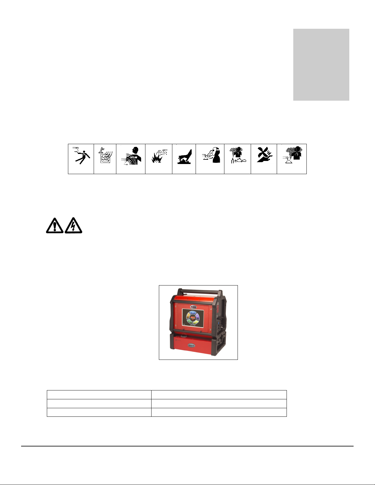
INTRODUCTION
he Model 205 is a power source and controller for automatic orbital tube welding. It is
intended to be used only in conjunction with AMI or EXEL orbital tube weldheads.
The Model 205 power supply provides GTAW (Gas Tungsten Arc Welding) current
with pulsation controls, high frequency arc starting, purge gas controls, weldhead arc
rotation and automatic timing functions. Users need only to supply input AC power, a
regulated gas source with flow meter and the appropriate weldhead.
NOTICE
This document and the information contained herein is the property of Arc Machines, Inc. It
is proprietary and submitted and received in confidence. It shall be used only for the
purpose for which it is submitted and shall not be copied in whole or in part without the prior
express written permission of Arc Machines, Inc. The information in this document has
been carefully reviewed and is believed to be accurate. However, no responsibility is
assumed for inaccuracies.
Information and instructions in this document are subject to change and Arc Machines, Inc.
reserves the right to change specifications and data without notice.
i

M O D E L 2 0 5
O P E R A T O R ’ S M A N U A L
Revision History
Rev ECO No.
Change Description Date Appr.
A N/A Initial release 3/10/09 B.F.
B 5355 Update sections 2.0, 3.0, 4.0, 5.0 & 6.0; delete Glossary 5/14/09 B.F.
C 5411 Update section 4.10.9 Performing a Weld 07/06/09 B.F.
D 5447 CE changes 12/30/09 D.C.
E 5713 Correct table in Section 6.1.2 with correct weight 06/16/10 D.C.
F 5817 Incorporate S/W v1.5, corrections for CE changes, add
12/08/10 D.C.
power grounded to section 2.0, update obsolete data
G 6346 Incorporate M21 W/H information, add changes to Run
06/15/12 D.C.
screen, add Associated Data look-up tables, add
information on system initiate 0.5 second delay, add
information on +1%/-1% buttons, update UK address.
H 6518 Section 6.2, changed picture of Remote Pendant (pg51) 3/20/13 BL
J 6646 Add Weld Data Recording functionality and update
2/25/14 W.O.
applicable screens
ii
ii
iiii

M O D E L 2 0 5
O P E R A T O R ’ S M A N U A L
Table of Contents
Table of Contents
Table of ContentsTable of Contents
INTRODUCTION.................................................................................................... i
NOTICE..............................................................................................................i
Revision History ............................................................................................ii
Table of Contents .........................................................................................iii
1.0 SAFETY PRECAUTIONS...................................................................... 1
1.1 SHOCK HAZARD WARNING................................................................ 1
1.2 WARNING LABEL DEFINITIONS ......................................................... 3
2.0 SPECIFICATIONS .................................................................................5
2.1 ELECTRICAL ........................................................................................ 5
2.2 ELECTICAL SERVICE GUIDE .............................................................. 6
2.3 PHYSICAL DIMENSIONS .....................................................................6
2.4 PROGRAMMABLE AND OPERATIONAL FUNCTIONS ...................... 7
3.0 INITIAL SETUP......................................................................................8
3.1 SYSTEM SYMBOLS..............................................................................8
3.2 INSPECTION .......................................................................................10
3.3 POWER CONNECTION....................................................................... 11
3.4 WELDING GAS CONNECTIONS ........................................................ 11
3.5 MODEL 205 TO M8 / M9 WELDHEAD HOOK UP ..............................12
3.6 MODEL 205 TO EXEL ROTOR DRIVER HOOK UP........................... 16
3.7 MODEL 205 TO M21 WELDHEAD HOOK UP ....................................17
4.0 OPERATION........................................................................................ 18
4.1 SYSTEM FUNCTIONS......................................................................... 18
4.2 INITIAL POWER ON............................................................................20
4.3 SET-UP FUNCTIONS ..........................................................................21
4.4 OPENING THE LAST WELD SCHEDULE ..........................................25
4.5 SELECTING A WELD SCHEDULE FROM THE LIBRARY ................25
4.6 MODIFY A WELD SCHEDULE ...........................................................26
4.7 COPY A WELD SCHEDULE ...............................................................30
4.8 CREATE A WELD SCHEDULE........................................................... 33
4.9 WELDHEAD CALIBRATION...............................................................35
4.10 PERFORMING A WELD.....................................................................36
4.11 WELD DATA RECORDING................................................................40
5.0 MAINTENANCE AND TROUBLE-SHOOTING ................................... 43
6.0 OPTIONS.............................................................................................52
iii
iii
iiiiii

M O D E L 2 0 5
Hazard
Chapter
1
O P E R A T O R ’ S M A N U A L
1.0 SAFETY PRECAUTIONS
The Model 205 is intended to be used only with AMI or EXEL weldheads for the purpose of
GTAW welding of metal tube. The system is not to be used for any other purpose, specifically
heating or cutting.
WARNING
I C O N K E Y
Warning
Electrical
THAT HE HAS READ AND/OR BEEN MADE AWARE OF ALL OF THE SAFETY-RELATED
ITEMS CONTAINED IN THIS MANUAL.
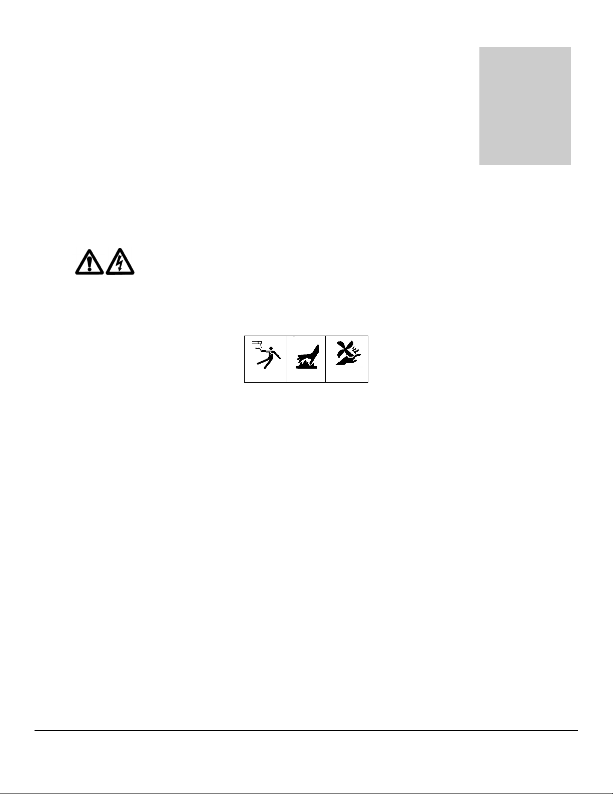
The nature of the GTAW process creates some POTENTIAL
HAZARDS. In accordance with international safety regulations the
EXCLAMATION SYMBOL indicates that this equipment is considered
HAZARDOUS. The LIGHTNING FLASH SYMBOL indicates that
there are potential electrical hazards. The use and display of these
symbols make it the OPERATOR’S RESPONSIBILITY TO ENSURE
1.1 SHOCK HAZARD WARNING
HIGH VOLTAGE is present on exposed internal terminals. The ELECTRODE (tungsten /
weldhead rotor) is also an EXPOSED TERMINAL and by its nature the GTAW process requires
electrical potential to be present on the electrode during arc starting and during welding.
1
M O D E L 2 0 5
O P E R A T O R ’ S M A N U A L
All AMI Power Supplies contain a “bleeder” circuit to ground any residual potential
after welding or after an aborted or bad arc start attempt. These circuits take a few seconds
to operate or could fail.
The electrode should always be considered a possible shock hazard. This is
especially true when the system is in “weld sequence”, ready to weld, is welding or has just
finished welding. Equipment/component failure, system abuse or improper maintenance
could result in electrical potential at the weldhead even when not in “weld sequence”.
The users/operators of this equipment must take all precautions necessary to avoid
contact with the ELECTRODE at “ALL TIMES”. The only exception is when actually
replacing or adjusting the electrode and this should be done WITH THE POWER TURNED
OFF.
If performed with the power “ON” the system must be in “TEST” mode out of weld
sequence and the USER MUST OBSERVE COMMON SAFETY PRACTICES such as
grounding the electrode to ensure discharge before actually touching it.
Most AMI Power Supplies feature High Frequency (HF) Arc Starting. This is a High
Voltage/High Frequency electrical transmission process. To eliminate any HF shock
possibility “AVOID ALL CONTACT” with the Welding WORK (ground), the ELECTRODE or
the WELDHEAD during arc start.
Remember, there is a possible shock hazard in all welding power supplies at
ALL times.
2222
M O D E L 2 0 5
O P E R A T O R ’ S M A N U A L
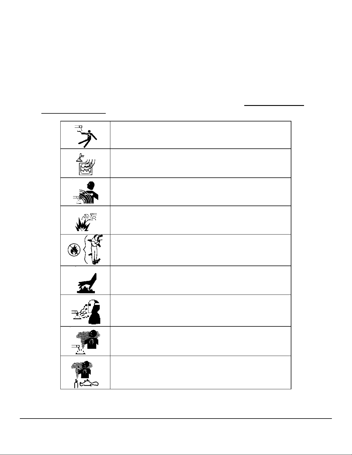
1.2 WARNING LABEL DEFINITIONS
The table below contains caution and warning labels for the operation of this equipment. Before
operating this or any welding equipment users should be familiar with ANSI-49.1 Safety in
Welding and Cutting.
ELECTRIC SHOCK from welding electrode or wiring can kill.
HIGH FREQUENCY RADIO WAVES can cause interference and
sometimes even damage to nearby electronic equipment (such
as computers) that are un-protected.
MAGNETIC FIELDS can affect implanted medical devices.
Wearers of pacemakers should keep away until consulting their
doctor.
Welding can cause FIRE OR EXPLOSIONS. Do not weld near
FLAMMABLE or EXPLOSIVE MATERIALS. Have the proper
type of extinguisher in the work area.
WEAR NON-FLAMMABLE protective clothing, footwear and
head gear at all times.
HOT PARTS can cause severe burns. Do not touch recently
welded components. Avoid touching torch components and
welding fixtures soon after welding.
ARC RAYS can burn the eyes and skin. The welding arc emits
ultra-violet (UV) radiation and the molten weld gives off infra-red.
Both can burn eyes and skin if unprotected. Suitable eye and skin
protection must be worn.
BUILD UP OF GAS can injure or kill. Weld materials can emit
toxic fumes during welding. WELD ONLY IN AREAS WITH
ADEQUATE VENTILATION.
FUMES AND GASES can be hazardous. Welding produces
fumes and gases. Breathing these fumes and gases can be
hazardous to your health. DO NOT weld in enclosed areas
without proper ventilation or respirators.
3333
M O D E L 2 0 5
O P E R A T O R ’ S M A N U A L
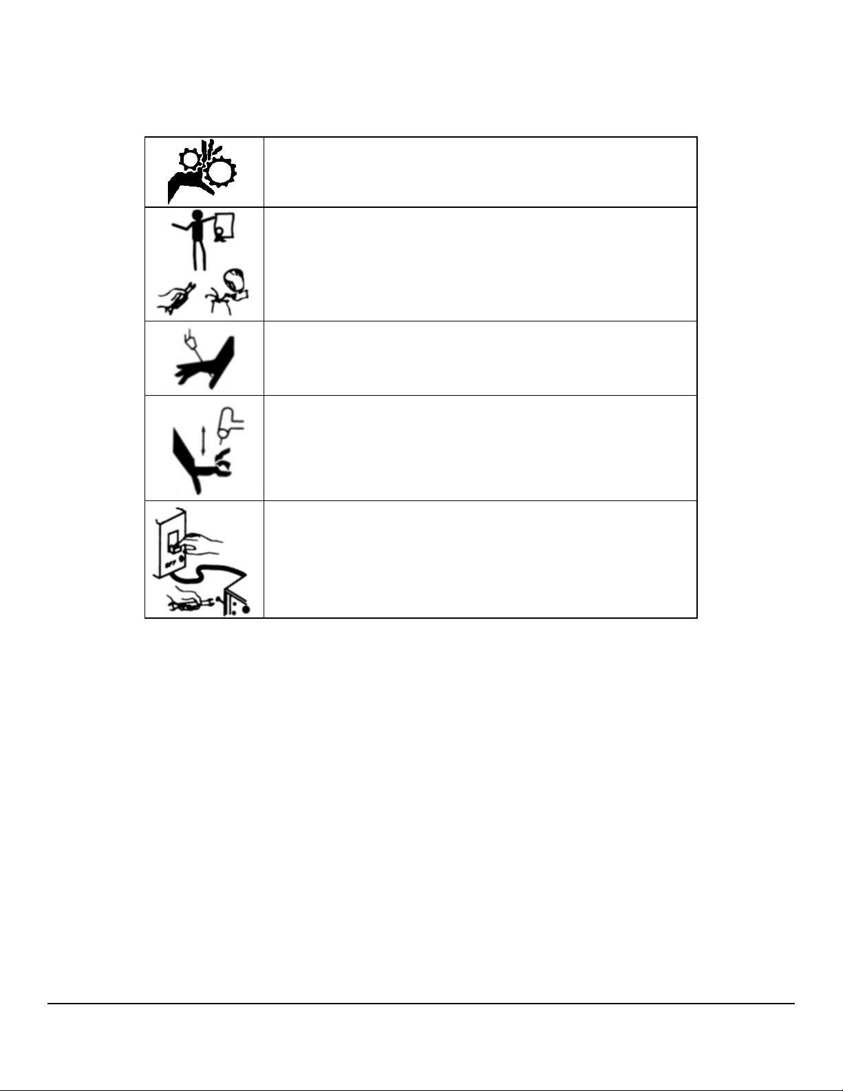
MOVING PARTS - Keep hands and fingers clear of fans,
gears, rotors, wire feed, rotation and AVC mechanisms
WARNING: AMI factory training is essential for all Welding
Operators and Maintenance Technicians who operate AMI
equipment.
WELDING WIRE and ELECTRODES are sharp and can cause
injury.
MOVING PARTS may cause crush or pinch points.
WARNING: Disconnect the input power to the machine before
opening or servicing. Discharge all circuits that store high
voltage such as capacitor packs. Only AUTHORIZED and
QUALIFIED service personnel should open this equipment.
4444

M O D E L 2 0 5
90V
90V
90V
90V
Chapter
2
O P E R A T O R ’ S M A N U A L
2.0 SPECIFICATIONS
These specifications pertain the to Model 205 power supply only. For weldheads, refer to the
specification sheet of each particular model. For non-AMI supplied equipment such as gas
tanks and regulators, refer to the original manufacturer’s documentation.
The Model 205 is a mobile system that is intended be hand carried. The supporting equipment
such as weldheads, water coolers, gas regulators, remote controls and extension cables can
also be hand carried. Items such as gas tanks and welding fixtures should be moved with
appropriate equipment and safety precautions. Gas tanks should be securely anchored to
prevent toppling over.
2.1 ELECTRICAL
INPUT POWER DETAIL
The Model 205 can operate on the following Auto Adjusting for Single Phase AC input:
Input Power
Single-Phase
AC
115 Volts TIG
20A
230 Volts TIG
20A
Rated Welding
Output
100A @ 14.0
Volts DC, 100%
Duty Cycle
150A @ 16.0
Volts DC, 30%
Duty Cycle
100A @ 14.0
Volts DC, 100%
Duty Cycle
150A @ 16.0
Volts DC, 30%
Duty Cycle
Welding
Amperage
Range
5 - 150A
5 - 150A
5 - 150A
5 - 150A
Max OCV
DC (Up)
12-16
12-16
12-16
12-16
Rated Peak
Starting
Voltage (Up)
15 KV 18.4 2.1 2.1
15 KV 28 3.4 3.1
15 KV 8.3 2 1.9
15 KV 14.2 3.2 3.1
Amperes Input
At Rated Load
Output, 50/60Hz,
Single-Phase
KVA
@
Duty
Cycle
KW
Input power must be grounded.
5555

M O D E L 2 0 5
O P E R A T O R ’ S M A N U A L
OUTPUT POWER
Straight polarity, constant current DC regulation intended for GTAW welding only. Static
characteristic of all power supplies is flat.
5 to 150 amperes DC using 100 to 120 VAC input.
5 to 150 amperes DC using 200 to 240 VAC input.
CIRCUIT BREAKER – ON/OFF, two pole, 20 Ampere at 250 VAC.
DUTY CYCLE – determined by the AC input voltage and the required output current. The
Model 205 system has an internal thermal sensor that will limit operation should the
temperature exceed the safe operating parameters.
2.2 ELECTICAL SERVICE GUIDE
FUNCTION RANGE
INPUT VOLTAGE 115/230
INPUT AMPERES AT RATED OUTPUT 13.1
MAX RECOMMENDED STD FUSE RATING IN AMPERES
• CIRCUIT BREAKER, TIME DELAY
• NORMAL OPERATING
15
20
MIN INPUT CONDUCTOR SIZE IN AWG 14
MAX RECOMMENDED INPUT CONDUCTOR
LENGTH IN FEET (METERS)
91 (28)
MIN GROUNDING CONDUCTOR SIZE IN AWG 14
2.3 PHYSICAL DIMENSIONS
POWER SUPPLY HEIGHT 18” (457mm)
POWER SUPPLY WIDTH 19” (483mm)
POWER SUPPLY DEPTH 14” (356mm)
POWER SUPPLY WEIGHT 51 lbs (22 kg)
6666

M O D E L 2 0 5
O P E R A T O R ’ S M A N U A L
2.4 PROGRAMMABLE AND OPERATIONAL FUNCTIONS
SINGLE ENTRY FUNCTIONS
FUNCTION RANGE
PREPURGE 5.0 – 999.0 seconds
POSTPURGE 5.0 – 999.0 seconds
UPSLOPE 0.0 – 99.9 seconds
START LEVEL 5.0 – 150.0 amps
DOWNSLOPE 00.0 – 99.9 seconds
LEVEL ADVANCE TIME / POSITION
TRAVEL START DELAY 00.0 – 99.9 seconds
TRAVEL DIRECTION CW / CCW
MULTI-LEVEL FUNCTIONS
The following functions can be programmed at each level to change value during a
given weld sequence.
FUNCTION RANGE
LEVEL POSITION 0 – 9999 degrees
LEVEL DEGREES 0 – 9999 degrees
SLOPE DEGREES 0 – 9999 degrees
TIME 0.1 – 999.9 seconds
SLOPE TIME 0.0 – 999.9 seconds
PRIMARY AMPS * 5.0 – 150.0 amps
BACKGROUND AMPS 5.0 – 150.0 amps
PRIMARY TRAVEL As defined by Weldhead **
BACKGROUND TRAVEL As defined by Weldhead **
PRIMARY PULSE 0.01 – 9.99 seconds
BACKGROUND PULSE 0.01 – 9.99 seconds
PULSE MODE ON / OFF
TRAVEL MODE ON / STEP / CONT
* For single level schedules the PRIMARY AMPS function is replaced by START AMPS and
END AMPS functions
** TRAVEL functions are in 0.01 RPM increments
7777
M O D E L 2 0 5
Chapter
3
O P E R A T O R ’ S M A N U A L
3.0 INITIAL SETUP
This manual is intended to assist users of this equipment in set up and basic
operation. It is NOT INTENDED AS A SUBSTITUTE FOR FACTORY TRAINING.
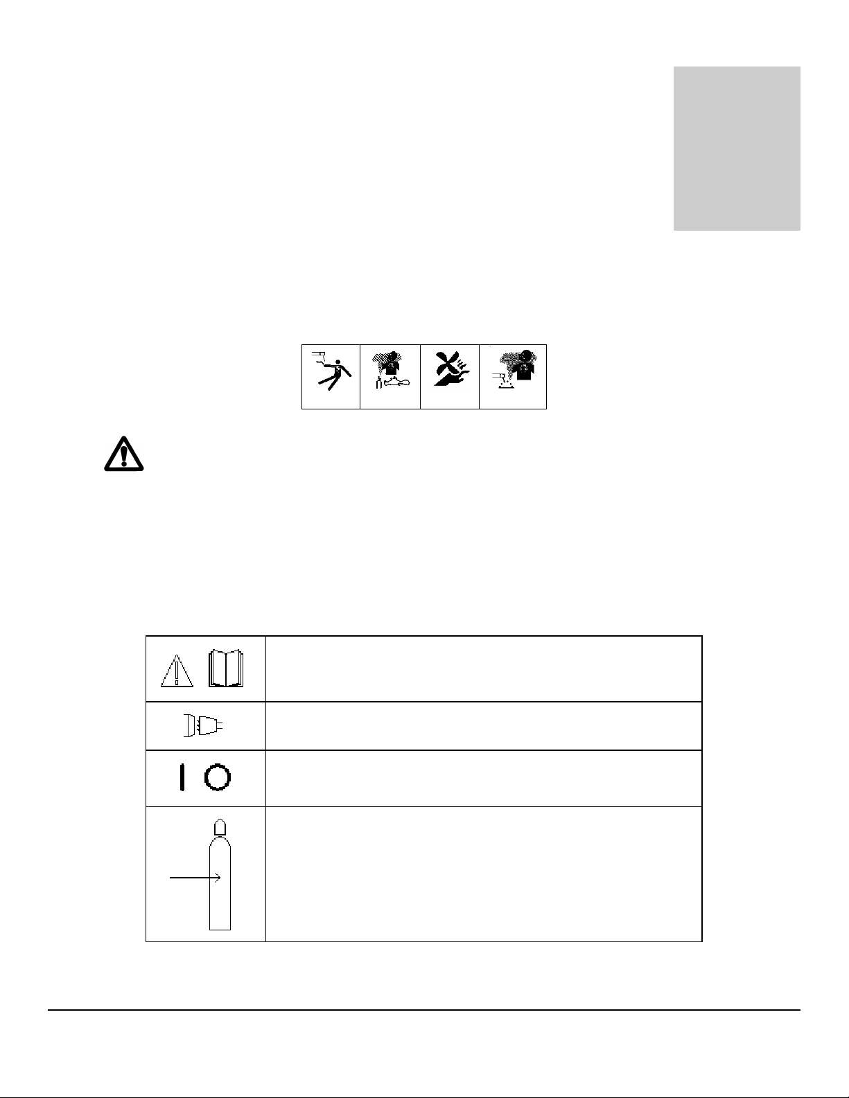
3.1 SYSTEM SYMBOLS
The following symbols are present on the Model 205 version 13B050100-02
Revision NC and up:
WARNING: Read this manual! This document contains
information that could help prevent injury or damage to the
equipment.
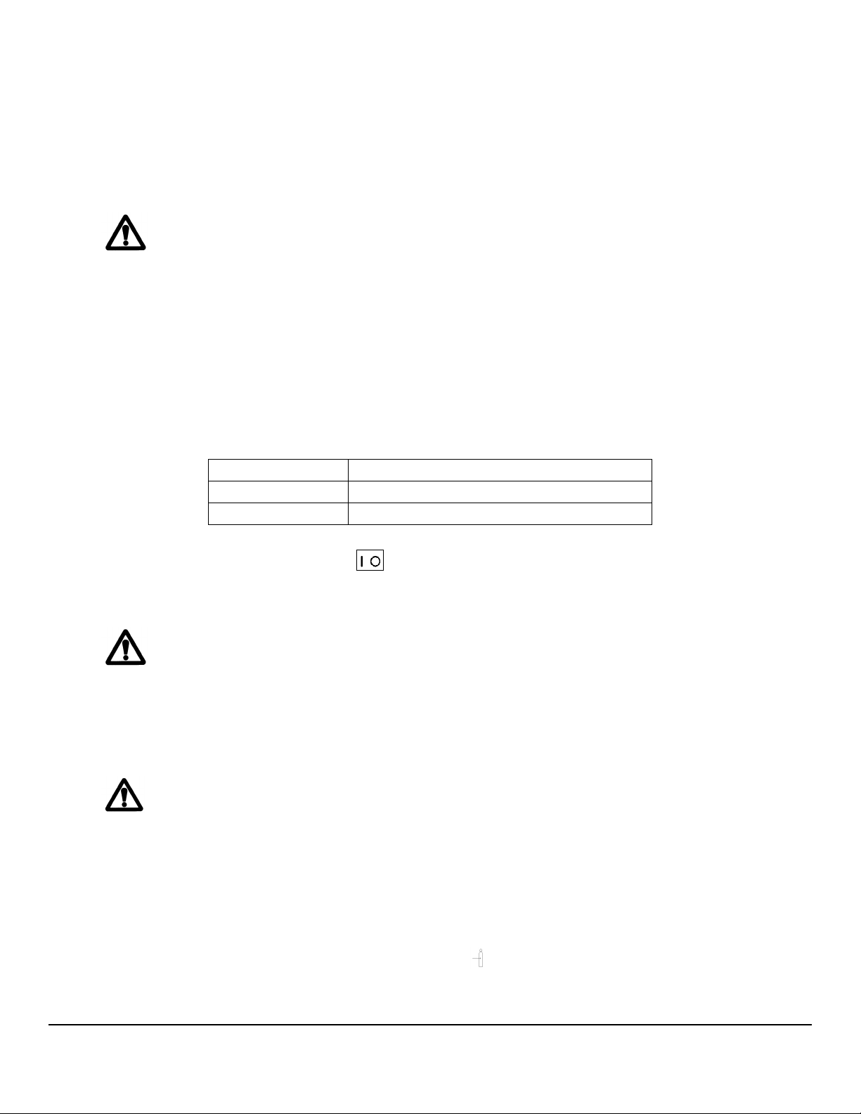
115/230 VAC INPUT - AC mains input, 100-240 volts AC,
50/60 Hz.
ON OFF - On/Off switch (circuit breaker).
ARC GAS INPUT - input for the arc shielding gas. An external
regulator and flow indicator must be used.
8888
M O D E L 2 0 5
O P E R A T O R ’ S M A N U A L
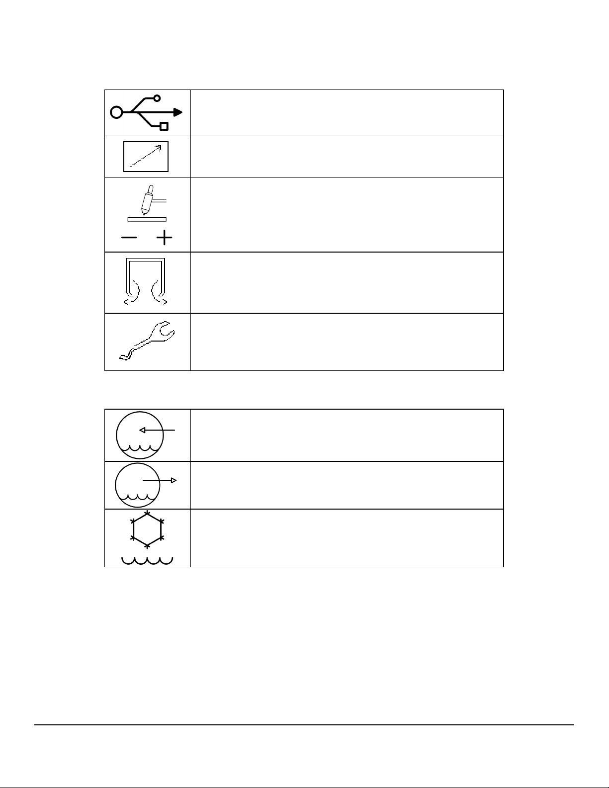
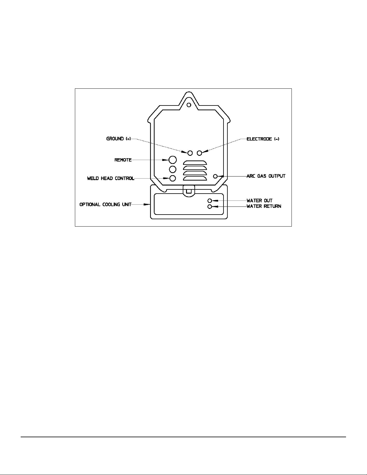
USB - USB port. Devices should not be left plugged in while
welding.
REMOTE - Remote control connection
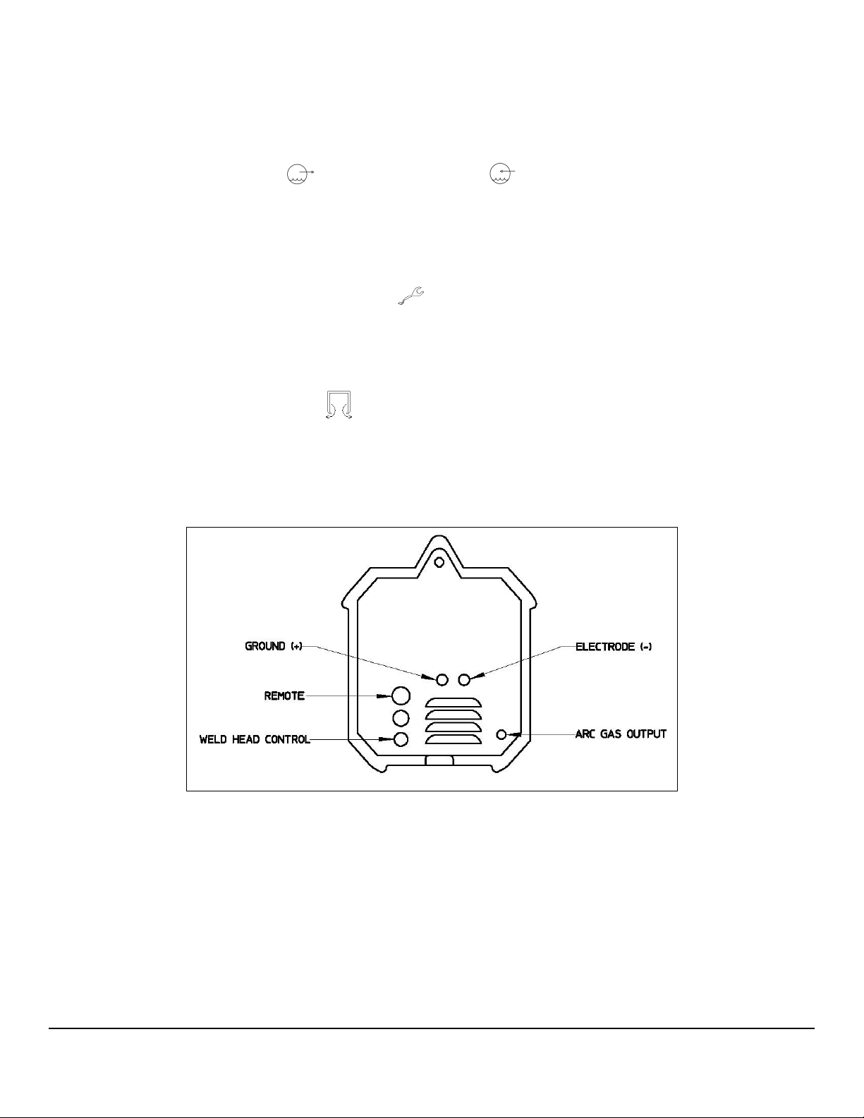
GROUND(+) ELECTRODE(-) - weldhead ground and electrode
connections.
ARC GAS OUTPUT - output for the arc shielding gas connection.
WELDHEAD CONTROL - weldhead motor control. Intended for
AMI and EXEL weldheads only.
The optional water cooler M205-CW is marked with the following symbols:
WATER RETURN - cooling water input.
WATER OUT - cooling water output.
Cooling liquid tank fill opening.
9999

M O D E L 2 0 5
O P E R A T O R ’ S M A N U A L
3.2 INSPECTION
The Model 205 is shipped with a variety of peripheral equipment such as gas hoses, fittings and
cables. An exact list of these items is included with each power supply shipment and should be
located prior to setup.
• After unpacking, inspect all items for obvious physical damage and loose parts. If
damage is evident, contact a factory representative before using. If water
condensation is apparent, dry the unit before using.
• Check all fittings and connectors for proper seating and ensure that all protective
boots are in place. If the unit is not properly seated or protected short circuits, poor
connections or inert gas leaks could occur.
• Ensure that all cables are routed and protected in such a way that they will not be
subject to heat or equipment / personnel traffic. Ensure that the cables DO NOT
come in contact with HOT PIPE.
• For operation the Model 205 must be placed on a flat level surface capable of
supporting the weight of the unit, cables, and any other options. The Model 205
can be mounted on top of the optional water cooler provided the installation will
not cause the unit to topple over.
• Check the gas and coolant hoses (if used) to ensure that they are not pinched or
bent as this will restrict flow.
• Ensure that the Model 205 has adequate air flow and the intakes and exhaust vents
are not restricted.
• Ensure that there is bare metal contact between the weldhead components which
connect to GROUND (clamp inserts, etc.) and the tube to be welded.
10
10
1010
M O D E L 2 0 5
O P E R A T O R ’ S M A N U A L
3.3 POWER CONNECTION
To avoid severe equipment damage ensure that the Model 205 power supply is
connected to the correct input AC power as listed in Section 2.0 Specifications.
The Model 205 can operate on any single phase voltage from 100V AC to 240V AC.
Provided the input voltage is within this range, the unit will automatically adjust for the input
voltage.
1. The Model 205 is supplied with a 15 foot power cord. A suitable AC line connector
matching the input power must be supplied and installed by the user. Color coding of
the power cord is as follows:
Green/Yellow: Equipment grounding conductor
White/Gray: Grounded circuit conductor, Neutral
Black: Ungrounded circuit conductor, Line
2. Ensure that the circuit breaker is in the down or OFF position.
3. Connect the AC line connector to the power cord.
Do not connect the Model 205 to the AC power source until all installation
steps are complete
3.4 WELDING GAS CONNECTIONS
The Model 205 is intended for typical GTAW gases ONLY. NEVER CONNECT
OXYGEN OR ACETYLENE TO THE MODEL 205.
1. The Arc Gas hose is supplied with the Model 205. This hose is made of material
selected specifically for automatic welding. HOSES MADE FROM OTHER
MATERIAL ARE NOT RECOMMENDED (especially rubber, nylon, or tygon).
2. This 10 foot (3 meter) hose should be installed from the gas regulator/flow meter
(user supplied) to the ARC GAS INPUT fitting on the Model 205. The hose is
supplied with the fittings required to mate with the Model 205 and most domestic
(USA) inert gas flow meters.
11
11
1111
M O D E L 2 0 5
O P E R A T O R ’ S M A N U A L
3. The arc gas is controlled by a solenoid and flow sensor in the Model 205. Attach the
input gas line to ARC GAS INPUT fitting on the Model 205, NOT DIRECTLY TO
THE WELDHEAD.
4. Attach the other end of the input gas hose to the gas regulator/flow meter. Fitting it
loosely by hand, tighten the nut slightly with a wrench to ensure there are no leaks.
DO NOT OVER TIGHTEN. The use of plumbers tape or grease is NOT
RECOMMENDED.
The Model 205 arc gas solenoid valve is rated at 50 PSI (345 kPa) maximum
pressure, DO NOT EXCEED THIS RATING.
3.5 MODEL 205 TO M8 / M9 WELDHEAD HOOK UP
Always turn the power supply off before making any cable or connection
changes to the power supply.
Non-liquid-cooled weldheads (Models 9-250 and 9-500) connect directly to the Model
205. Liquid-cooled weldheads connect to the Model 205 via a short pig-tail or via an
adapter cable. If needed an extension cable can be used. The extension cable
connects to the Model 205, then to the weldhead for non liquid-cooled weldheads or to
the adapter cable for liquid-cooled weldheads.
Pig-tail Connections
1. Connect the ground and electrode brass quick-disconnect fittings on the pig-tail to
the mating fittings on the weldhead. Pull the knurled ring on the female fitting back
and fully insert the male fitting. These connectors are fully seated when the ring will
spring back to its original position. Slide the rubber boots together and secure them
in place, being careful not to dislodge the connectors. Male boots should cover the
connection first. The boots protect the connectors and prevent shorting to ground.
2. Attach the ground and electrode connectors on the pig-tail to their respective
GROUND(+) and ELECTRODE(-) terminals on the Model 205. Align the
keyways, push in and turn clockwise until fully locked.
12
12
1212

M O D E L 2 0 5
O P E R A T O R ’ S M A N U A L
3. Insert the two coolant line quick-disconnect fittings on the pig-tail into the mating
WATER OUT and WATER RETURN connectors on the Model 205-CW.
These connectors are interchangeable so either connector may be connected to
either mating fitting. To prevent accidental disconnection after making the
connection, finger-tighten the lock screw on the male connectors.
4. Attach the weldhead control male connector on the weldhead to the WELDHEAD
CONTROL connector on the Model 205. Note the positioning keyway and
NEVER FORCE or use tools on the cable connectors. Hand-tighten the connecting
ring being careful not to cross-thread the ring.
5. Insert the male gas quick-disconnect fitting on the weldhead to the mating ARC GAS
OUTPUT connector on the Model 205 and hand-tighten the lock screw to
prevent accidental disconnection. Slide the rubber boot over the connection.
Adapter Cable Connections
1. Connect the ground and electrode brass quick-disconnect fittings on the adapter
cable to the mating fittings on the weldhead. Pull the knurled ring on the female
fitting back and fully insert the male fitting. These connectors are fully seated when
the ring will spring back to its original position. Slide the rubber boots together and
secure them in place, being careful not to dislodge the connectors. Male boots
should cover the connection first. The boots protect the connectors and prevent
shorting to ground.
2. Attach the weldhead control male connector on the weldhead to the mating
weldhead control female connector on the adapter cable. Align the keyways and
carefully screw the retaining ring in place. DO NOT use tools and be careful not to
cross-thread the fitting. To help prevent damage screw the connector dust caps to
each other.
3. Insert the male gas quick-disconnect fitting on the weldhead to the mating female
fitting on the adapter cable. Hand-tighten the lock screw to prevent accidental
disconnection. Slide the rubber boots over the connection and secure them
together.
4. Attach the ground and electrode connectors on the adapter cable to their respective
GROUND(+) and ELECTRODE(-) terminals on the Model 205. Align the
keyways, push in and turn clockwise until fully locked.
13
13
1313
M O D E L 2 0 5
O P E R A T O R ’ S M A N U A L
5. Insert the two coolant line quick-disconnect fittings on the adapter cable into the
mating WATER OUT and WATER RETURN connectors on the Model 205-
CW. These connectors are interchangeable so either connector may be connected
to either mating fitting. To prevent accidental disconnection after making the
connection, finger-tighten the lock screw on the male connectors.
6. Attach the weldhead control male connector on the adapter cable to the
WELDHEAD CONTROL connector on the Model 205. Note the positioning
keyway and NEVER FORCE or use tools on the cable connectors. Hand-tighten the
connecting ring being careful not to cross-thread the ring.
7. Insert the male gas quick-disconnect fitting on the adapter cable to the mating ARC
GAS OUTPUT connector on the Model 205 and hand-tighten the lock screw to
prevent accidental disconnection. Slide the rubber boot over the connection.
Fig. 1
Hookups for Non-Liquid Cooled Weldheads
14
14
1414
M O D E L 2 0 5
O P E R A T O R ’ S M A N U A L
Hookups for Liquid Cooled Weldheads
Fig. 2
15
15
1515

M O D E L 2 0 5
O P E R A T O R ’ S M A N U A L
3.6 MODEL 205 TO EXEL ROTOR DRIVER HOOK UP
Always turn the power supply off before making any cable or connection
changes to the power supply.
The EXEL rotor driver (Model RDR-005) connects directly to the Model 205. The rotor
driver has NO connections to the M205-CW Cooling Unit.
1. Attach the ground and electrode connectors on the rotor driver to their respective
GROUND(+) and ELECTRODE(-) terminals on the Model 205. Align the
keyways, push in and turn clockwise until fully locked.
2. Attach the weldhead control male connector on the rotor driver to the WELDHEAD
CONTROL connector on the Model 205. Note the positioning keyway and
NEVER FORCE or use tools on the cable connectors. Hand-tighten the connecting
ring being careful not to cross-thread the ring.
3. Insert the male gas quick-disconnect fitting on the rotor driver to the mating ARC
GAS OUTPUT connector on the Model 205 and hand-tighten the lock screw to
prevent accidental disconnection. Slide the rubber boot over the connection.
Note
Note: for installation of the other components of the EXEL weldhead assembly
(rotor unit and fixture) see the Exel Welding System Rotor Units and Rotor Driver
Operation Manual, P/N 740111.
16
16
1616

M O D E L 2 0 5
O P E R A T O R ’ S M A N U A L
3.7 MODEL 205 TO M21 WELDHEAD HOOK UP
Always turn the power supply off before making any cable or connection
changes to the power supply.
Note
Note: for hook up of the M21 weldhead see the Model 21 Weldhead Operation
Manual, P/N 740122.
17
17
1717

M O D E L 2 0 5
Chapter
4
O P E R A T O R ’ S M A N U A L
4.0 OPERATION
Operation covers those steps that must be taken to enter a weld schedule and perform
a weld.
Ensure that the operator has installed the Model 205 per Section 3.0 and has a good
understanding of system functions (Section 4.1).
Ensure that the system is protected against dirt, dust, etc. NEVER GRIND NEAR AN
EXPOSED WELDHEAD OR THE MODEL 205.
Protect the system from water and liquid spray. Do not use the system if excessive
moisture is present.
4.1 SYSTEM FUNCTIONS
The Model 205 is intended for use with AMI or EXEL orbital welding heads and has
functions designed for these weldheads. This section describes what these functions are
and may, where needed for clarification, indicate how they are commonly, but not always,
used.
• LIBRARY - The heart of the Model 205 is its MEMORY. The values of each parameter for a
given weld are only programmed one time. After that the Model 205 will store the parameter
values by schedule NAME, DIAMETER, WALL thickness, and MATERIAL.
The operator may find a particular weld schedule by scrolling through the library listings or
by using the SEARCH feature which can search by DIAMETER, WALL thickness or
MATERIAL.
18
18
1818

M O D E L 2 0 5
O P E R A T O R ’ S M A N U A L
• WELD SEQUENCE AND LEVELS – A weld schedule is started by manually initiating
Sequence Start. Once the sequence is started, the system operation of functions is fully
automatic.
A weld schedule has the ability to change values for most functions as the electrode
traverses around the tube. The weld schedule is broken down into LEVELS and each level
can contain a change to one or more functions. A weld schedule can contain up to 100
levels. The advance from level to level is automatic and can be programmed by time or
degrees.
• TRAVEL FUNCTION – The system is equipped with a motor servo controller that
provides the power and regulation for rotating the electrode around weld seam. The
rotation is programmed in revolutions per minute (RPM) and can be programmed to
rotate continuously or stepped (synchronized with current pulsation).
• PULSATION – The system can rapidly change or pulse back and forth between two
different values of current and two different values of rotation travel. The HIGH value is
designated as the PRIMARY value and the LOW value is designated as the
BACKGROUND value. The pulsation rate is programmed by setting both the PRIMARY
and BACKGROUND PULSE timers.
• FAULT STATUS – The system monitors arc gas flow, arc volts and power supply
temperature. If any of these functions fall outside certain limits the system will alert the
operator and weld schedule will be halted (See Section 5.3).
• GAS FUNCTIONS – As stated, the Model 205 is intended for the GTAW process. This
process requires a welding gas (usually inert) for operation. The Model 205 is equipped
with a gas solenoid and input/output connectors for the control of the welding gas. Flow
rates are not controlled by the power supply and must be set via an external flow meter.
• PRINT FUNCTIONS – A thermal printer is built into the Model 205. It will print the library
of weld schedules as well as the programmed values and associated data of a specific
weld schedule.
• WELD DATA RECORDING – The system has the capability of recording data from the
weld. This data is feedback data from both the Travel and Current servos and is
recorded every 0.1 second. This data is saved to the hard drive of the Model 205 as a
Weld Data Record. The name of the Weld Data Record is a concatenation of the Power
Supply & Power Supply Serial Number & Weld Schedule Name & Weld ID. This record
can be exported to a USB memory stick to be loaded to a PC then viewed / printed.
Note
A Weld Data Record can ONLY be created in Weld Mode and ONLY when Weld Data
Recording is enabled.
19
19
1919

M O D E L 2 0 5
O P E R A T O R ’ S M A N U A L
4.2 INITIAL POWER ON
Before proceeding with POWER ON it is EXTREMELY important to have a basic
understanding of SYSTEM FUNCTIONS. Read Section 4.1 - System Functions before
proceeding.
1. Before connecting or energizing the AC power verify that all input power set up
requirements of Section 3.0 have been complied with.
2. Connect the AC power cable to the AC source and to the 115/230 VAC INPUT
connector on the Model 205. Move the circuit breaker to the ON position.
3. If the Model 205-CW is installed connect the AC cord to 110 or 220 VAC, single phase
power. Set the ON/OFF switch to the ON position.
Note
The Model 205-CW contains a flow sensor. The green lamp indicates that there is
sufficient flow. If this lamp goes out either the water level is too low or there is a
blockage in the line. Add coolant or clear the blockage before continuing to weld.
4. Boot-up and display the HOME screen takes approximately one minute.
20
20
2020

M O D E L 2 0 5
O P E R A T O R ’ S M A N U A L
4.3 SET-UP FUNCTIONS
The SET UP screen is used for the initial configuration of the power supply. Use this
screen to set up the following functions:
Date/Time setting
Password setting
Language selection
Language Update
DATE/TIME SETTING
1. From the HOME screen press SETUP.
2. From the SETUP screen select each Date and Time field to be changed.
Enter the new date and time data on the 10-key pad, then press ENTER.
When all data has been entered press the SET DATE/TIME button to set the
new date and time.
PASSWORD SETTING
The Model 205 can be set up to require a password entry to use the machine.
Your unit is shipped to you with no password requirement.
1. OPERATOR: An Operator may load and run any weld schedule but may
not create, change, delete, or copy a weld schedule.
21
21
2121

M O D E L 2 0 5
O P E R A T O R ’ S M A N U A L
2. SUPERVISOR: A Supervisor may load and run any weld schedule. In
addition, a Supervisor may create, change, delete, or copy a weld schedule.
3. PROGRAMMER: A Programmer has the same level of access as a
Supervisor and in addition can delete or change the Operator, Supervisor
and Programmer passwords, perform all Setup functions, calibrate the
Model 205 and create, change or delete languages.
1. From the Home screen press SETUP.
2. From the ENTER PASSWORD screen enter the Programmer password.
3. Press CHANGE OPERATOR, SUPERVISOR, or PROGRAMMER
PASSWORD.
4. Enter the old password into the OLD PASSWORD field (or leave blank if
no password is assigned).
5. Enter the password into the NEW PASSWORD field.
6. Re-enter the password into the CONFIRM PASSWORD field.
7. Press ENTER.
8. Re-boot the system – from the Home screen press SHUTDOWN then
press YES on the Shut Windows screen. Wait for the screen to go blank
before turning off the circuit breaker.
TO DELETE OR CHANGE A PASSWORD:
1. From the HOME screen press SETUP.
2. From the ENTER PASSWORD screen enter the Programmer password.
3. You may now select which password to delete or change by pressing
CHANGE OPERATOR PASSWORD, CHANGE SUPERVISOR
PASSWORD or CHANGE PROGRAMMER PASSWORD and follow the
steps above. Setting blank fields in the NEW PASSWORD and CONFIRM
NEW PASSWORD fields will delete the password.
TO SETUP A PASSWORD:
TO RESTORE A PASSWORD:
1. If you have lost or forgotten your password contact AMI Service
Department to obtain a one-day password. This will restore access to the
unit and allow you to set up new passwords.
LANGUAGE SELECTION
The Model 205 contains multiple pre-programmed languages. In addition, you may
customize a language or create a new language by replacing existing button names or
data entry titles with your own description.
Selecting one of the pre-programmed languages:
1. From the HOME screen press SETUP.
2. From the SETUP screen press LANGUAGE.
3. Select any of the languages displayed.
22
22
2222

M O D E L 2 0 5
O P E R A T O R ’ S M A N U A L
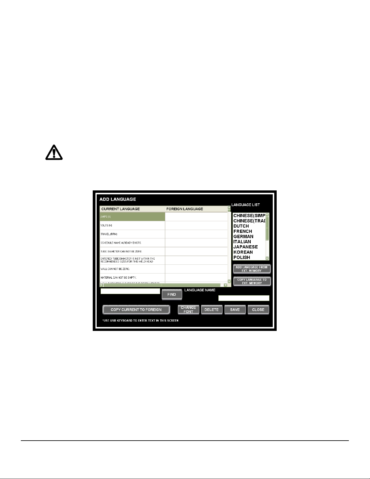
LANGUAGE UPDATE
Customizing a pre-programmed language or creating a language from a
pre-programmed language:
1. Insert a USB memory stick in the Model 205 USB port.
2. From the HOME screen press SETUP.
3. From the SETUP screen press ADD LANGUAGE.
4. Select a language from the list that the new language will be based on.
5. Enter the word to be changed in the textbox and press FIND (note: the
search is case sensitive)
6. Type the new word in the FOREIGN LANGUAGE column.
7. When you are finished making your changes you may overwrite the
existing language and keep the original name or enter a new name in the
LANGUAGE NAME field.
8. Press SAVE.
Changing a language Font, Style and Size:
The words in some languages require more letters than others. To fit additional
characters into all fields the font, style and/or size may need to be changed.
1. From the HOME screen press SETUP.
2. From the SETUP screen press ADD LANGUAGE.
3. Select the language to be changed.
4. Press CHANGE FONT.
5. Select a different Font, Style and/or Size and press OK.
6. Press SAVE to overwrite this language or enter a new name in the LANGUAGE
NAME textbox and press SAVE.
Deleting a language:
1. From the HOME screen press SETUP.
2. From the SETUP screen press ADD LANGUAGE.
3. Select the language to be deleted from the list and press DELETE.
Copy a language to External Memory:
1. Insert a USB memory stick in the Model 205 USB port.
2. From the HOME screen press SETUP.
3. From the SETUP screen press ADD LANGUAGE.
4. Select a language from the LANGUAGE LIST
5. From the ADD LANGUAGE screen press COPY LANGUAGE TO EXT
MEMORY.
6. When the Windows® Browse for Folder screen displays, select the external
memory location: D.
7. Press OK.
23
23
2323
M O D E L 2 0 5
O P E R A T O R ’ S M A N U A L
Add a language from External Memory:
1. Insert a USB memory stick in the Model 205 USB port.
2. From the HOME screen press SETUP.
3. From the SETUP screen press ADD LANGUAGE.
4. From the ADD LANGUAGE screen press ADD LANGUAGE FROM EXT
MEMORY.
5. When the Windows® Open screen displays, select the language file in the
external memory to be added (*.lgv file).
6. Press OK.
When adding a language from external memory the language MUST be formatted for
the Model 205 software otherwise the screens will be corrupted when this language is
selected.
24
24
2424

M O D E L 2 0 5
O P E R A T O R ’ S M A N U A L
4.4
4.4 OPENING THE LAST WELD SCHEDULE
4.44.4
Skip to Step 4.8 if no weld schedules are stored in the library.
1. From the HOME screen, press OPEN LAST.
OPENING THE LAST WELD SCHEDULE
OPENING THE LAST WELD SCHEDULEOPENING THE LAST WELD SCHEDULE
4.5
4.5 SELECTING A WELD SCHEDULE FROM THE LIBRARY
4.54.5
Skip to Step 4.8 if no weld schedules are stored in the library.
1. From the HOME screen, press LIBRARY.
2. Weld schedules will be listed from newest to oldest. Select a weld schedule then
SELECTING A WELD SCHEDULE FROM THE LIBRARY
SELECTING A WELD SCHEDULE FROM THE LIBRARYSELECTING A WELD SCHEDULE FROM THE LIBRARY
press LOAD.
25
25
2525

M O D E L 2 0 5
O P E R A T O R ’ S M A N U A L
Note
Use the UP or DOWN arrows to find additional weld schedules.
Note
You may search for and segregate weld schedules by DIAMETER, WALL or MATERIAL.
Select one or more of these categories from the 3 drop-down lists, select the weld schedule,
then press LOAD.
4.6 MODIFY A WELD SCHEDULE
Skip to Step 4.8 if no weld schedules are stored in the library.
1. From the HOME screen press OPEN LAST (to modify the last weld schedule
loaded) or LIBRARY to select and load a weld schedule from the Library.
26
26
2626

M O D E L 2 0 5
O P E R A T O R ’ S M A N U A L
2. From the RUN screen press SCHEDULE.
3. The first parameters displayed are the SINGLE ENTRY parameters. The MULTI-
LEVEL parameters and ASSOCIATED DATA parameters are accessed by using the
NEXT button on each screen.
Single Entry Parameters:
27
27
2727
M O D E L 2 0 5
O P E R A T O R ’ S M A N U A L
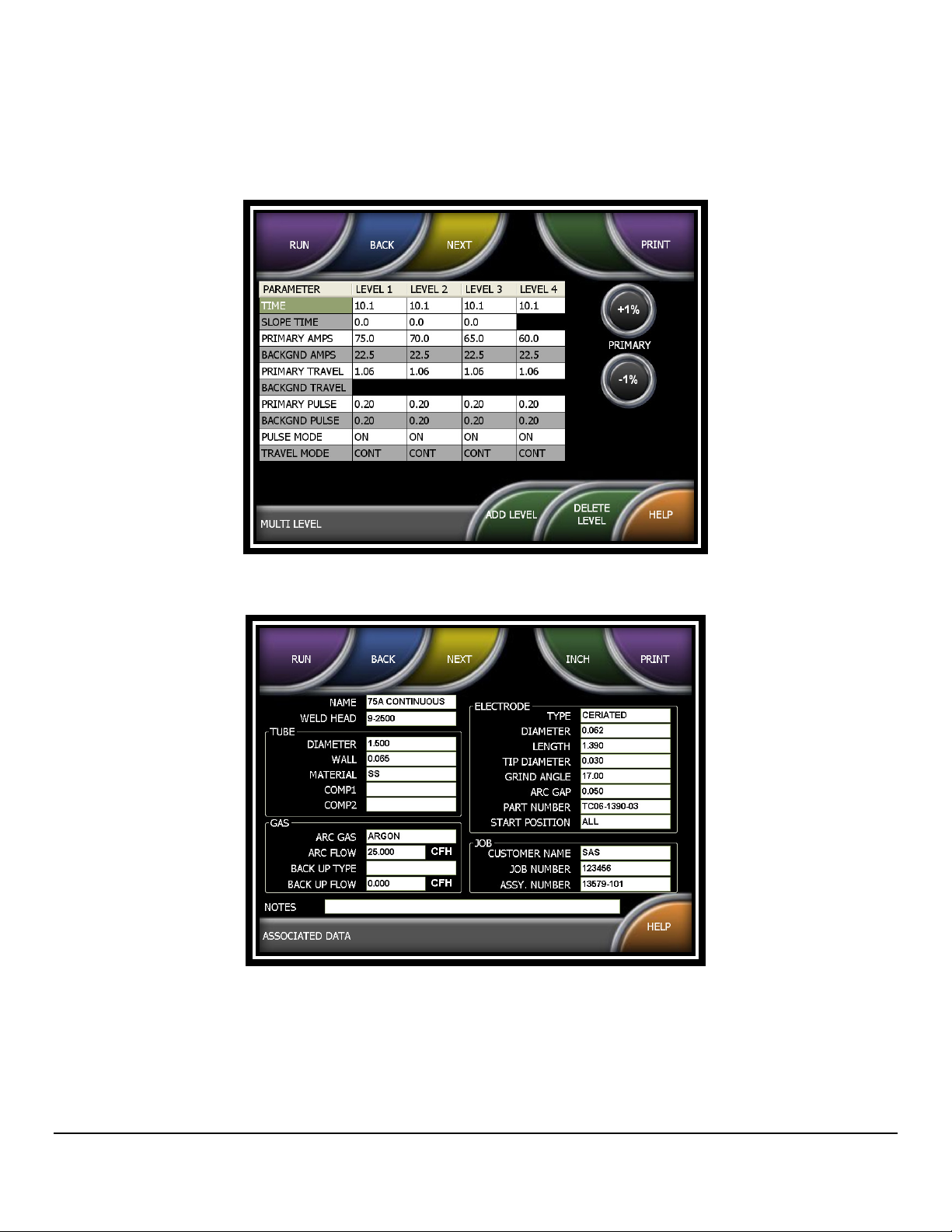
Multi-Level Parameters:
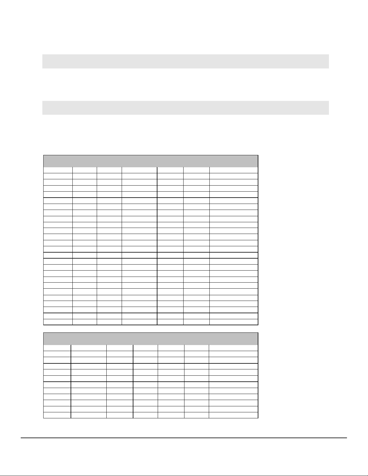
Associated Data Parameters:
4. Select each field to be modified and enter the text or value via the on-screen alpha-
numeric keyboard or 10-key pad, then press the RETURN or ENTER key. The
changes will automatically be saved.
28
28
2828
M O D E L 2 0 5
Length
Diameter
O P E R A T O R ’ S M A N U A L
Note
If the +1% or -1% button is pressed on the Multi Level screen the Primary Amps will
be incremented or decremented by this percentage. This is for the purpose of
‘tweaking’ the current to improve the quality of the weld.
Note
Associated Data parameters are information only. Electrode Diameter, Arc Gap,
Electrode Length and Part Number are calculated for M8 and M9 weldheads. For
EXEL and M21 weldheads these fields are populated from the following look-up
tables:
Rotor Unit Rotor OD Arc Gap Tube OD Electrode
RTU-004 0.796 0.035 0.125 0.301 0.040 TC04-0301-02
0.250 0.238 0.040 TC04-0238-02
RTU-008SL 1.696 0.035 0.125 0.750 0.040 TC04-0750-02
0.250 0.688 0.040 TC04-0688-02
0.375 0.626 0.040 TC04-0626-02
0.500 0.563 0.040 TC04-0563-02
RTU-008 1.814 0.035 0.125 0.809 0.040 TC04-0809-02
0.250 0.746 0.040 TC04-0746-02
0.375 0.685 0.040 TC04-0685-02
0.500 0.622 0.040 TC04-0622-02
0.625 0.560 0.040 TC04-0560-02
RTU-016SL 2.628 0.040 0.500 1.024 0.062 TC06-1024-02
0.750 0.899 0.062 TC06-0899-02
1.000 0.772 0.062 TC06-0772-02
RTU-032 3.75 0.045 0.500 1.580 0.062 TC06-1580-02
0.750 1.456 0.062 TC06-1456-02
1.000 1.331 0.062 TC06-1331-02
1.500 1.081 0.062 TC06-1081-02
2.000 0.830 0.062 TC06-0830-02
Electrode
P/N
Weld Head Tube OD Electrode
Length
M21-500 1/8" 0.395 0.020 0.040 0.005 TC04-0395-005
1/4 " 0.325 0.035 0.040 0.005 TC04-0325-005
3/8" 0.260 0.035 0.040 0.005 TC04-0260-005
1/2" 0.195 0.049 0.040 0.005 TC04-0195-005
M21-1000 1/4" 0.706 0.035 0.062 0.005 TC06-0706-005
3/8" 0.643 0.035 0.062 0.005 TC06-0643-005
1/2" 0.573 0.049 0.062 0.005 TC06-0573-005
3/4" 0.440 0.065 0.062 0.01 TC06-0440-01
1" 0.315 0.065 0.062 0.01 TC06-0315-01
Wall Electrode
Diameter
Diameter
29
29
2929
Tip
P/N

M O D E L 2 0 5
O P E R A T O R ’ S M A N U A L
4.7 COPY A WELD SCHEDULE
The Model 205 has the ability to make a copy of a weld schedule and save it under a
new name in the Model 205 Library.
You may also copy one or all weld schedules stored in the Model 205 Library and save
them to a USB Memory stick, or copy one or all weld schedules on a USB memory stick
and save them to the Model 205 Library.
• Copy a weld schedule in the Model 205 Library
1. From the HOME screen press LIBRARY then select the weld schedule to be
copied.
2. Press COPY. Enter a new schedule name and press either SAVE or
RETURN. The new schedule will be saved to the Library.
30
30
3030

M O D E L 2 0 5
O P E R A T O R ’ S M A N U A L
• View Weld Schedules Stored On a USB Stick
1. Insert a USB memory stick into the USB port on the Model 205.
2. From the HOME screen press LIBRARY.
3. From LIBRARY press VIEW USB.
• Copy one or all weld schedules in the Model205 Library and save to a USB
memory stick.
1. Insert a USB memory stick into the USB port on the Model 205.
2. From the HOME screen press LIBRARY.
3. Select a weld schedule to be copied and press COPY.
4. For copying one weld schedule to a USB stick press COPY TO USB. For
copying ALL weld schedules to a USB stick, press COPY ALL TO USB.
31
31
3131

M O D E L 2 0 5
O P E R A T O R ’ S M A N U A L
• Copy one or all weld schedules from a USB memory stick to the Model 205
Library
1. Insert a USB memory stick into the USB port on the Model 205.
2. From the HOME screen press LIBRARY, then press VIEW USB.
3. Select the weld schedule to be copied and press COPY TO M205. If copying
all weld schedules press COPY ALL TO M205.
32
32
3232

M O D E L 2 0 5
O P E R A T O R ’ S M A N U A L
4.8 CREATE A WELD SCHEDULE
The Model 205 provides two versions of manual weld schedule creation: Manual Multi level
and Manual S3 (Single Level Sloped) and four versions of Automatic weld schedule
generation: Auto Continuous Travel, Auto Stepped Travel, Auto Tack, and Auto S3.
1. From the HOME screen press CREATE NEW.
2. Enter the Weld Schedule NAME.
3. Enter the DIAMETER, WALL and, MATERIAL.
4. Press the WELDHEAD MODEL field and select the weldhead that you will be using.
Note
Use the ENTER key (on the displayed 10-key pad) or the RETURN key (on the
displayed keyboard) to SAVE each entry before making an entry into the next field.
Note
The Name, Diameter, Wall and Material will be displayed in the Library. The Diameter,
Wall, and Weldhead Model will be used for establishing welding parameters for
Automatic Weld Schedule generation.
5. Toggle the INCH key to select inches or millimeters to represent the size of the tube to
be welded.
33
33
3333

M O D E L 2 0 5
O P E R A T O R ’ S M A N U A L
6. The welding parameters may now be entered manually by selecting either MANUAL
MULTI or MANUAL S3, or a weld schedule may be automatically generated by
selecting AUTO CONTINUOUS TRAVEL, AUTO STEPPED TRAVEL, AUTO TACK,
or AUTO S3.
• Manual Multi – this option allows the entry of a multi-level weld schedule. You may
program up to (and not including) 100 levels. Electrode rotation can be either
continuous or stepped (synchronized with current pulsation).
• Manual S3 – this program allows the entry of an S3 weld schedule. An S3 schedule
is a single-level program that ramps the current down over the course of the weld
rather than stepping it down via multiple levels. This ramping is programmed by
selecting a starting amps (START AMPS), a background amps, and an ending amps
(END AMPS). Over the course of the weld the amps will ramp down to the value
programmed into END AMPS while pulsing between the ramping down starting
amps value and the background amps value.
• Auto Continuous Travel – this version of automatic programming will create a 4-
level weld schedule with electrode rotation in the continuous mode.
• Auto Stepped Travel – this version of programming will create a 4-level weld
schedule with electrode rotation in the stepped mode. In this case the electrode
rotation will be synchronized with the current pulsation. The most common method
used rotates the electrode during the background amps and stops the electrode
rotation during the primary amps.
34
34
3434
M O D E L 2 0 5
O P E R A T O R ’ S M A N U A L
• Auto S3 – this version of automatic programming will generate a single-level
program that continually ramps the current down over the course of the weld. This
ramping is established by programming a starting amps (START AMPS) and an
ending amps (END AMPS).
• Auto-Tack – this type of auto programming creates a weld schedule for tacking. You
may specify the approximate depth of tack penetration, the number of tacks, and a
tacking sequence – sequential or balanced.
4.9
4.9 WELDHEAD
4.94.9
Any time a different weldhead or weld schedule is selected the weldhead must be calibrated
to that weldhead and schedule.
1. Load the weld schedule from the Library. When the RUN screen opens press
WELDHEAD CALIBRATION
WELDHEADWELDHEAD
CALIBRATE.
CALIBRATION
CALIBRATION CALIBRATION
2. Check to be sure that it is safe to run the weldhead rotation and press START.
3. The calibration process rotates the electrode twice around at two different speeds.
At the completion of calibration the screen will display CALIBRATION COMPLETED.
If the calibration fails, an adjustment to the weldhead calibration potentiometer is
required.
35
35
3535

M O D E L 2 0 5
O P E R A T O R ’ S M A N U A L
If an adjustment to the weldhead’s calibration potentiometer is required the
screen will display
CALIBRATION FAILED – TURN TRIM POT CCW – TRY AGAIN
or
CALIBRATION FAILED – TURN TRIM POT CW – TRY AGAIN
4. Using the screw driver supplied with the weldhead turn the weldhead’s
potentiometer a few turns in the recommended direction and re-run the calibration
procedure (Steps 1 & 2). Continue these steps until the screen displays
CALIBRATION COMPLETED.
Note
M21 weldheads do NOT have a calibration potentiometer.
To prevent possible injury do not open the weldhead until the calibration process is
complete.
4444.10
.10 PERFORMING A W
.10.10
1. Install the weldhead per Section 3.5 and the specification sheet for the weldhead.
2. From the HOME screen press the LIBRARY key, select a weld schedule and press LOAD,
or use the OPEN LAST key to access the last schedule used.
3. Before performing the weld calibrate the weldhead to the schedule being used per Section 4.9.
This is required when a different schedule and/or weldhead is used.
4. Install the correct tungsten and the material to be welded into the weldhead as described in
the weldhead manual.
5. Turn on the gas source at the regulator/flow meter. Press the PURGE button and set the
required flow rate for the weldhead being used. Continue manual purge until all lines are
filled with the gas and all moisture and impurities have been removed. Turn the purge OFF
by pressing the PURGE button again.
Note
The font on the PURGE button turns red when it is activated.
PERFORMING A WELD
PERFORMING A WPERFORMING A W
ELD
ELDELD
Note
If for any reason the Operator leaves the Weld screen the manual purge will stop.
36
36
3636

M O D E L 2 0 5
O P E R A T O R ’ S M A N U A L
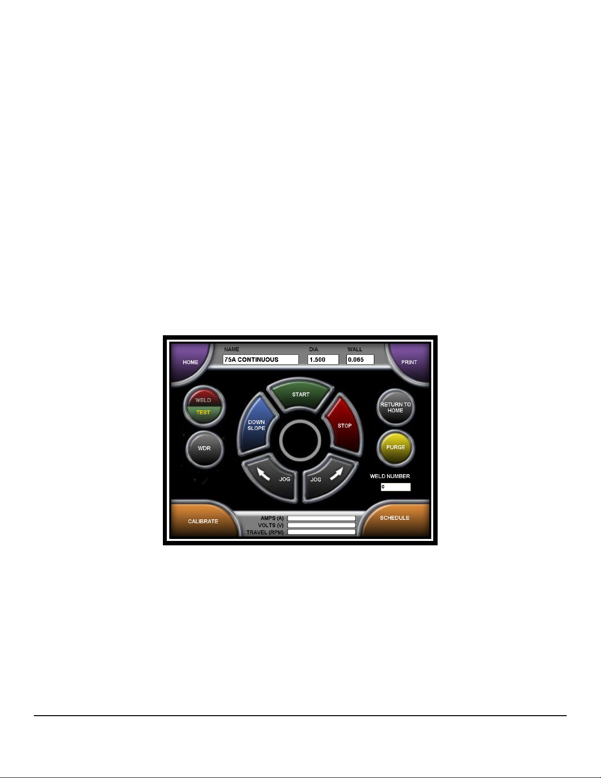
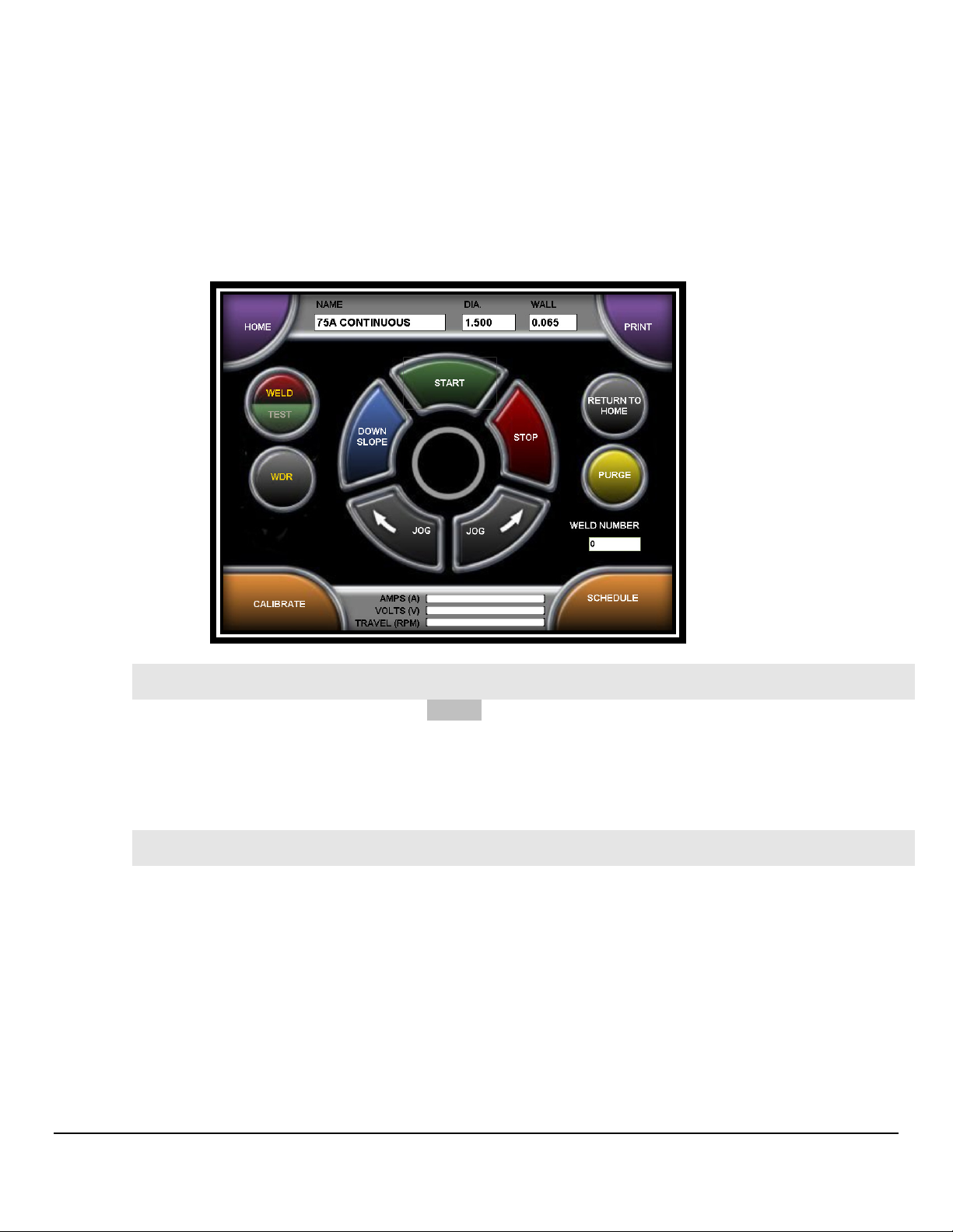
6. The Model 205 features a WELD/TEST button. In the TEST mode the unit will allow for
electrode rotation but will not strike an arc. The WELD or TEST font on the button turns yellow
to indicate which mode the system is set to.
7. When you are ready to start welding press the WELD/TEST button to put the power supply
in WELD mode.
8. Press START to initiate the weld. The center of the RUN screen displays a count-down of
each weld sequence.
Note
For M21 weldheads refer to the Model 21 Weldhead Operation Manual on how to initiate and
stop a weld sequence.
37
37
3737

M O D E L 2 0 5
O P E R A T O R ’ S M A N U A L
9. Once the operator manually presses the START button the following events will
occur automatically:
• EVENT 1: PREPURGE - welding gas will start to flow and continue to flow for the entire
weld sequence from the gas source through the power supply to the weldhead.
Complete gas coverage should be obtained before the arc is struck. How long it flows
before the arc is struck is called the PREPURGE time. Minimum programmable time is
5 seconds. Refer to the on line HELP for minimum recommended PREPURGE time for
each weldhead.
• EVENT 2: ARC START - when PREPURGE time is complete the gas will continue to
flow and a high frequency pulse will be generated to establish an arc between the
electrode and the weld joint.
Note
When the system initiates it waits for 0.5 second for either an arc start or arc fault response.
• EVENT 3: UPSLOPE - when an UPSLOPE is programmed the arc will be initiated at the
programmed START LEVEL amps. As soon as the arc is established the amps will
ramp up to the programmed Level 1 PRIMARY AMPS value. When an UPSLOPE is not
programmed, the arc will be initiated at the Level 1 PRIMARY AMPS value.
Once the arc is established and PULSE MODE programmed to ON the weld current will
pulse between the PRIMARY and BACKGROUND amp values. The amount of time it
remains at these values is determined by the PRIMARY and BACKGROUND PULSE
times.
In most cases, rotation of the arc should not begin until full penetration of the weld has
been achieved. Once the arc is established the TRAVEL START DELAY time will begin
to count. When this time has counted down, the weld schedule will advance to Level 1
and begin rotating the electrode at the Level 1 programmed travel speed for the Level 1
programmed number of seconds or degrees of rotation.
After the TRAVEL START DELAY time is complete, the electrode will begin to travel in
one of the 3 programmable PULSE MODES:
OFF - Prevent rotation from occurring.
CONTINUOUS - Rotates the electrode continuously at the PRIMARY TRAVEL
speed, regardless of PULSE MODE.
STEP - Rotates the electrode, alternating between the PRIMARY TRAVEL speed
and the BACKGROUND TRAVEL speed. This function is synchronized to the
PRIMARY PULSE time and the BACKGROUND PULSE time.
38
38
3838

M O D E L 2 0 5
O P E R A T O R ’ S M A N U A L
Note
The electrode rotation direction is a Single Entry function and cannot be programmed to
change direction during a weld.
• EVENT 4: LEVEL 1 and FOLLOW-ON LEVELS - at the end of TRAVEL START
DELAY the program will automatically advance to Level 1 and then to follow-on
levels.
If programmed by DEGREES the electrode will rotate to position programmed in each
level before advancing to the next level. If programmed by TIME the electrode will rotate
for the amount of time programmed in each level.
• EVENT 5: DOWNSLOPE – at the end of the last level over the course of the
programmed DOWNSLOPE time both primary and background amps will ramp
down while continuing to pulse until the arc is extinguished.
• EVENT 6: POSTPURGE – once the arc is extinguished the POSTPURGE time
begins counting down. During this time the arc gas continues to flow into the
weldhead.
• EVENT 7: RETURN TO HOME – at the end of the POSTPURGE the gas will
shut off, the weldhead rotor will return to its HOME position, and the Weld
Number will update.
• COMPLETE: after the rotor has returned to its HOME position the welded tube
can be removed from the weldhead.
• Press the PRINT button to print the Weld Schedule if desired.
DO NOT attempt to open the weldhead to remove the weld until the rotor has
returned to its home position.
39
39
3939

M O D E L 2 0 5
O P E R A T O R ’ S M A N U A L
4.11
4.11 WELD DATA RECORDING
4.114.11
• Setup and Enable Weld Data Recording
1. Press WDR to open the Weld Data Recording screen.
WELD DATA RECORDING
WELD DATA RECORDINGWELD DATA RECORDING
2. Enter data in each of the fields
Note
Power Supply Model Number, Power Supply Serial Number and Weldhead Model Number
are already stored in the system so these fields are automatically filled.
Note
The ONLY required field is Weld ID and it must be unique. If a non-unique value is entered
(Weld Camino de las Estrellas ID that has already been used) an error message will be
displayed.
3. Press WDR ENABLED to turn on Weld Data Recording.
40
40
4040
M O D E L 2 0 5
O P E R A T O R ’ S M A N U A L
• Record Weld Data
1. Press RUN to return to the Weld screen.
2. Toggle WELD/TEST to WELD.
Note
The font on the WDR button turns yellow if Weld Data Recording is enabled AND Weld/Test
is set to Weld.
3. Press START to start the weld sequence and the Weld Data Recording
Note
The font on the WDR button turns red while the weld data is being recorded.
• Export Weld Data Record
1. Insert a USB memory stick into the USB port on the Model 205.
2. Press WDR to return to the Weld Data Recording screen.
41
41
4141

M O D E L 2 0 5
O P E R A T O R ’ S M A N U A L
3. Press EXPORT WDR FILE to select a WDR file and an export destination.
4. Press OK
Note
The OK button will ONLY be enabled when BOTH the Source and Destination fields are
filled. The Destination will normally be the D:\ drive which is the USB memory stick.
5. Repeat steps 3 and 4 to export additional WDR files.
6. Remove the USB memory stick and load on a PC to view / print the weld data
record(s).
Note
The exported weld data record(s) will be in *.csv format and can be opened in Microsoft
Excelor Notepad.
42
42
4242
M O D E L 2 0 5
Chapter
5
O P E R A T O R ’ S M A N U A L
5.0 MAINTENANCE AND TROUBLE-SHOOTING
Always disconnect the AC power cable from the line voltage before
attempting to work with this welding power supply.
5.1 GENERAL MAINTENANCE
• COOLANT - the water tank in the optional Model 205-CW cooling unit holds
approximately 0.75 gallons (2.8 liters) of fluid. Check the fluid level periodically. The
use of different weldheads will remove fluid from the tank over a period of time. Fill
the tank per instructions in Section 6.1 COOLING UNIT.
• Cleaning exterior and interior surfaces. Prolonged use in dusty shop or outside
environments may cause the outside surfaces to accumulate a coating of dirt and
dust. Do not use shop air to blow dust particles away from the panels since it is
usually too wet. Use a vacuum cleaner with a soft brush. Where a vacuum brush
cannot reach use a clean soft paint brush and then vacuum.
• INPUT/OUTPUT PANEL CONNECTIONS - periodic inspection of the Model 205
panel as well as electrode/gas/water return quick-disconnects on all cables should
be performed. Damaged, dented or deformed connectors may cause poor or unsafe
operation and water or gas leakage. The O-ring inside the weldhead electrode and
gas quick-disconnects should be periodically cleaned and re-greased.
• Precautions to follow for storing or handling:
Always keep weldheads in the protective containers they are shipped in or in an optional
carrying case until ready for use. Residual coolant should be drained from the weldhead
cables to prevent corrosion.
43
43
4343

M O D E L 2 0 5
O P E R A T O R ’ S M A N U A L
Always keep the protective boots and dust caps on all connectors and fittings until cables
are ready to be installed. A major cause of downtime in any automatic welding system is
improper care and use of cables.
Take extreme care to avoid dropping the power supply or the weldheads.
Always disconnect the power input cable from the junction box or wall-plug
before cleaning.
DO NOT USE acid, corrosives or any liquid substance on the Model 205 or any AMI
weldhead. When cleaning use only a light solution of isopropyl alcohol on a soft cloth.
DO NOT ADD lubrication such as graphite, oil, or grease to the weldhead or power
supply unless it is specified in the operation manual for that equipment.
44
44
4444

M O D E L 2 0 5
O P E R A T O R ’ S M A N U A L
5.2 CURRENT OUTPUT CALIBRATION
This procedure is intended for calibration/verification of output current by the user. True
verification of current output for Quality Control purposes must be performed with a calibrated
External Calibration Shunt. This shunt may be obtained from Arc Machines, Inc. (Part Number
13B072511-01).
All personnel attempting to calibrate, trouble-shoot, or repair the Model 205 must be
familiar with its operation. They must understand the circuits and have a complete
understanding of the controls and their relationships.
All personnel must be aware of the location of hazardous voltage-carrying
conductors, terminals, heat sinks, etc. and must employ safety precautions when working
with the Model 205.
EQUIPMENT REQUIRED
• Digital Multimeter (DMM), minimum 4-digit readout. The meter must have
floating inputs (not connected to line or chassis ground) with a minimum of
1 mega ohm input impedance. Battery operated devices are recommend.
Suggested: Fluke Model 8060A or equivalent.
• AMI Fusion Weldhead rated for 150 amperes and a pipe or tube that will
not melt away with 150 amps applied. As an alternative a manual torch
can be set up on a flat plate (refer to Section 5.2.2).
• AMI External Shunt, 1 mV/amp, Part Number 13B072511-01 (optional).
• Argon or other acceptable GTAW gas source.
45
45
4545
M O D E L 2 0 5
O P E R A T O R ’ S M A N U A L
PROCESS
A weld schedule is required for calibration and will need to be created the first time a
calibration is done.
1. Set up a Weldhead rated for 150 amps continuous duty and insert a tube, pipe, or copper
rod that can withstand 150 amps of continuous current with no rotation. If these items are
not available then use a Hand Torch on a large plate with the torch fixed so it cannot
change the gap during calibration.
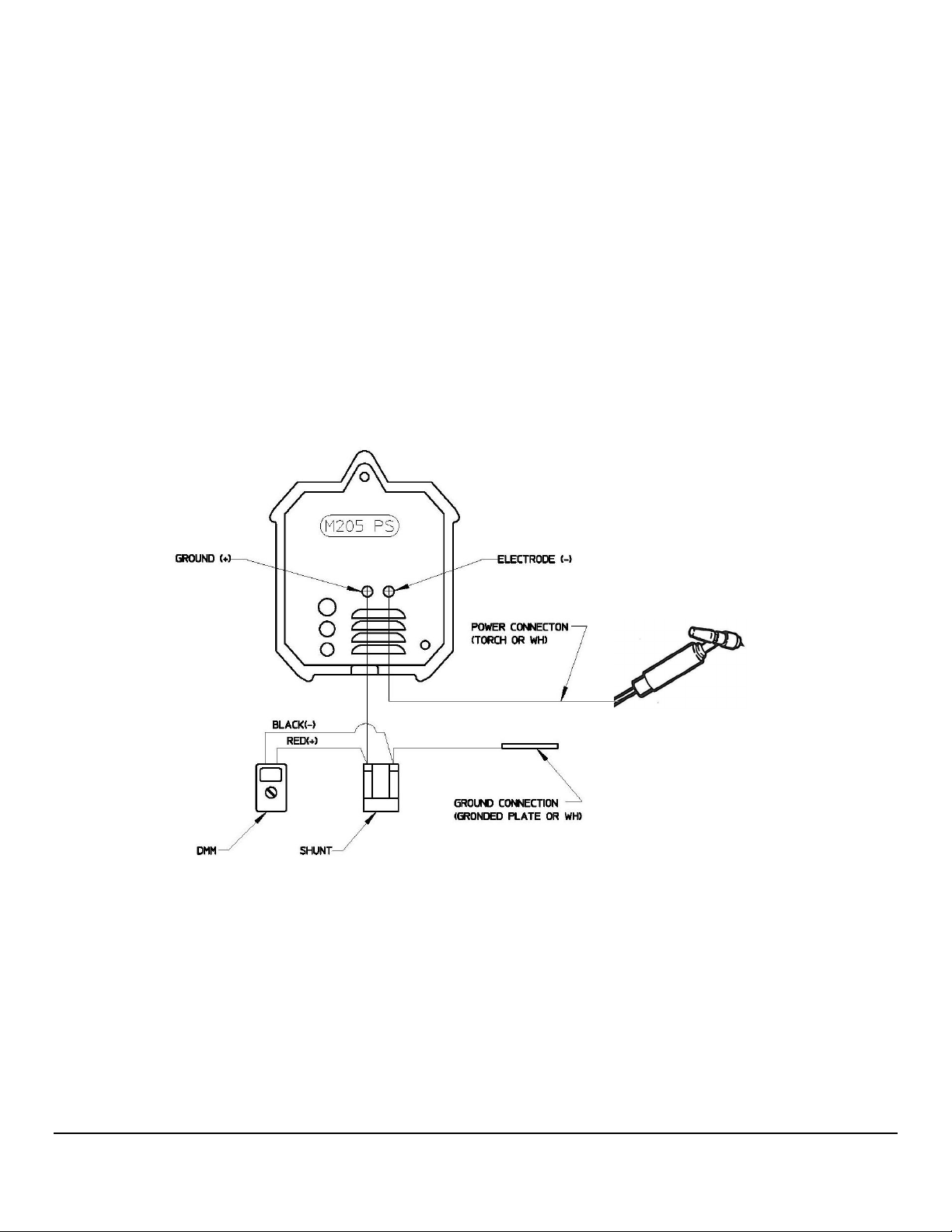
2. Connect the shunt between the ground connection on the power supply and the ground
connection on the weldhead or manual torch. Current is always measured along the return
path (Fig. 3).
Fig. 3
46
46
4646

M O D E L 2 0 5
O P E R A T O R ’ S M A N U A L
3. From the HOME screen press SETUP
4. From the SETUP screen press ADVANCED.
47
47
4747

M O D E L 2 0 5
O P E R A T O R ’ S M A N U A L
Note
To prevent unauthorized personnel from accessing the calibration feature a temporary
one-day password is required. Contact the AMI Service department for this password.
You will need the Power Supply serial number displayed on the HOME screen to obtain
this password.
5. Input the one-day password and press ENTER.
6. Setup the Digital Multimeter to read the 200 mVDC scale.
7. Prepare to insert the test probes into the red and black terminals on the shunt.
Any testing or recording instruments connected to any points in the machine or to the
welding head may be exposed to extremely high transient voltage at the time the arc starter
operates. ENSURE THAT ALL TEST EQUIPMENT IS DISCONNECTED DURING ARC START.
Make sure that when an arc is struck nothing will be overheated or melted.
Note
If an orbital weldhead is used instead of a manual torch you will need to hook up the
weldhead arc gas line to the power supply
48
48
4848

M O D E L 2 0 5
O P E R A T O R ’ S M A N U A L
8. The START button is located in the upper right corner of the screen. Once you have
determined it is safe to initiate an arc press START. After the arc is established connect
the black and red test probes from the DMM to the shunt (Fig. 3).
9. The weld schedule will remain at each Command level for 15 seconds and advance
through all 10 Commands. During this process make note of the DMM mV reading at each
Command.
10. At the conclusion of the weld sequence enter each of the DMM readings into the SHUNT
column.
11. Press HOME to return to the HOME screen
49
49
4949

M O D E L 2 0 5
O P E R A T O R ’ S M A N U A L
5.3 TROUBLESHOOTING
The Model 205 has the ability to monitor certain functions. If they are not working
correctly a system fault will alert the operator to the problem.
SYSTEM FAULT CORRECTIONS
When a System Fault occurs prior to or during welding it is required for the operator to
clear the fault condition before continuing.
Some faults are only temporary and the fault is corrected when the arc goes out. But all
faults will cause the FAULT SCREEN to appear and let the operator know why the
sequence was stopped.
The following is a general description of the cause of each type of fault and some
recommendation for correction. In all cases, when the fault is corrected the operator
must press the OK button to close the FAULT SCREEN.
• TEMPERATURE - the Model 205 has an internal temperature sensor (thermal switch).
If the Power Supply internal temperature rises above the safe limit, a TEMPERATURE
fault occurs. This can only occur if there is some type of blockage of air circulation, fan
failure, component failure within the Power Supply, or that the system is being operated
in ambient air temperatures above or below its rating of 0° C (32° F) and 45° C (104° F)
/ 95% humidity (non-condensing).
This Fault should only occur during an actual weld sequence. If it occurs when the
machine is not welding then a serious internal problem exists. In this case turn the
Power Supply OFF and call an AMI Service representative.
• GAS - this fault will occur at the beginning of a weld sequence or during a weld
sequence. If arc gas flow through the system should stop or fall below 7 CFH, a fault
will occur.
Check that the Gas Source is turned on and that adequate gas is available. Check all
gas hoses and connections for free flow. This is usually the problem.
50
50
5050

M O D E L 2 0 5
O P E R A T O R ’ S M A N U A L
If there is no problem with the source or with the hoses and their connections then an
internal failure of the flow switch, solenoid or internal hosing is possible. Contact an
AMI Service representative.
• ARC VOLTS LOW or STUB OUT - this fault will only occur when an arc is present and
will no longer exist when the arc goes out. If the arc voltage gets too low (below 5 volts)
or the electrode should touch the weld puddle an ARC VOLT fault will occur. This
creates an ALL STOP condition and does not actuate the RETURN TO HOME function
after Postpurge.
• ARC VOLTS HIGH - if the arc voltage is too high (above 20 volts) during a weld
sequence this fault will occur. It usually occurs if a hole is made in the weld, causing
the arc to wander over to the far side of the hole. The most common cause of this is
either poor tube fit-up or excessive gas pressure inside the tube causing the weld to
blow out and create a hole.
• BAD START - if for any reason the Model 205 cannot establish a stable arc at the end
of Prepurge the system will display a BAD START fault. There can be several reasons
for this to occur. The most common are poor ground or electrode connections,
contaminated gas or a contaminated electrode. Another common cause of a BAD
START is too short of a Prepurge time. This is especially true when a system or
weldhead is being used for the first time in a shift. While it sits unused atmosphere can
propagate into the cables. Before performing the first weld of a shift, use the Manual
Purge for a minute or two to initially clear the gas lines.
Note
AMI recommends 2% Ceriated welding electrodes. They have proven to be much
more effective than 2% Thoriated electrodes for RF transmission and are reported to
have longer life than 2% Thoriated Electrodes.
Note
There are no user serviceable components located inside the Model 205. Do not open
the unit in an attempt to repair it. Contact Arc Machines if the unit is malfunctioning or
suspected of being broken. As such no wiring diagram or internal circuit drawing is
provided.
51
51
5151
M O D E L 2 0 5
Chapter
6
O P E R A T O R ’ S M A N U A L
6.0 OPTIONS
The following are installation and operation instructions for Model 205 options. Some
options have their own manuals and these are not discussed in this section.
Always turn the power supply OFF before making any cable or connection
changes to the Model 205 power supply.
6.1 COOLING UNIT (Model 205-CW)
SPECIFICATIONS
AC INPUT POWER 90–260 VAC 1 Phase, 4 amps max.
COOLANT CAPACITY 0.75 gallons (2.8 liters)
CIRCULATION 0.5 GPM (2.8 LPM)
52
52
5252
M O D E L 2 0 5
O P E R A T O R ’ S M A N U A L
PHYSICAL CONSTRUCTION
MATERIAL Aluminum cabinet/Polyethylene tank
HEIGHT 6.25 inches (159 mm)
WIDTH 19.0 inches (483 mm)
DEPTH 14.0 inches (356 mm)
WEIGHT (with water) 27 lbs (12.3 kg)
WEIGHT (without water) 21.5 lbs (9.8 kg)
PUMP 60 PSI (413 kPa)
INSTALLATION
1. The cooling unit is shipped dry and requires 0.75 gallons (2.8 liters) of either:
• CLEAN DISTILLED or DE-IONIZED water
• CLEAN DISTILLED or DE-IONIZED water and OPTISHIELD® 'Plus' (mix per
manufacturer’s instructions)
• A 50/50 mixture of ethylene glycol and CLEAN DISTILLED or DE-IONIZED water
DO NOT USE automotive antifreeze or STOP-LEAK type antifreeze
2. Before mounting the Model 205-CW Cooling Unit to the Model 205 remove the fill cap
and add the coolant mixture. Replace the fill cap.
3. Place the Model 205 onto the Model 205-CW Cooling Unit and close the latches on each
end.
4. For connections to the weldhead see Section 3.5.
5. The Model 205-CW contains a flow sensor. The green lamp indicates that there is
sufficient flow. If this lamp goes out either the water level is too low or there is a
blockage in the line. Add coolant or clear the blockage before continuing to weld.
DO NOT OPERATE the water cooling unit WITHOUT coolant in the tank OR
WITHOUT a water flow path (water OUT to IN through a weldhead).
53
53
5353

M O D E L 2 0 5
O P E R A T O R ’ S M A N U A L
6.2 OPTIONAL REMOTE PENDANT
• Allows for the remote START/STOP of a weld sequence, JOG of the weldhead rotor,
manual gas PURGE, and return to HOME of the weldhead rotor.
• Attach the remote pendant connector to the REMOTE connector on the Model
205. Note the positioning keyway and NEVER FORCE or use tools on the cable
connectors. Hand-tighten the connecting ring being careful not to cross-thread the
ring.
Note
The EXEL RDR-005 rotor driver contains a built-in remote pendant which is fully
functional with the Model 205.
Note
The remote pendant cannot be connected if an M21 weldhead is being used.
Note
For additional available options, such as extension cables contact Arc Machines, Inc.
54
54
5454

M O D E L 2 0 5
O P E R A T O R ’ S M A N U A L
55
55
5555
 Loading...