

Page 1

Arcam T31 AM/FM tuner
Tuner FM/PO Arcam T31
Arcam AM/FM-Tuner T31
Page 2

3
Engl i s h
Safety guidelines
RISQUE DE CHOC ELECTRIQUE
NE PAS OUVRIR
ATTENTION
CAUTION
RISK OF ELECTRIC
SHOCK DO NOT OPEN
CAUTION: To reduce the risk of electric shock, do not
remove cover (or back). No user serviceable parts inside.
Refer servicing to qualified service personnel.
WARNING: To reduce the risk of fire or electric shock, do
not expose this apparatus to rain or moisture.
The lightning flash with an arrowhead symbol within an equilateral triangle,
is intended to alert the user to the presence of uninsulated ‘dangerous
voltage’ within the product’s enclosure that may be of sufficient magnitude to
constitute a risk of electric shock to persons.
The exclamation point within an equilateral triangle is intended to alert the
user to the presence of important operating and maintenance (servicing)
instructions in the literature accompanying the product.
CAUTION: In Canada and the USA, to prevent electric
shock, match the wide blade of the plug to the wide slot in
the socket and insert the plug fully into the socket.
IMPORTANT SAFETY INSTRUCTIONS
This product is designed and manufactured to meet strict quality
and safety standards. However, you should be aware of the following
installation and operation precautions:
1. Take heed of warnings and instructions
You should read all the safety and operating instructions before
operating this appliance. Retain this handbook for future reference
and adhere to all warnings in the handbook or on the appliance.
2. Water and moisture
The presence of electricity near water can be dangerous. Do not use
the appliance near water – for example next to a bathtub, washbowl,
kitchen sink, in a wet basement or near a swimming pool, etc.
3. Object or liquid entry
Take care that objects do not fall and liquids are not spilled into the
enclosure through any openings. Liquid filled objects such as vases
should not be placed on the equipment.
4. Ventilation
Do not place the equipment on a bed, sofa, rug or similar soft surface,
or in an enclosed bookcase or cabinet, since ventilation may be
impeded. We recommend a minimum distance of 50mm (2 inches)
around the sides and top of the appliance to provide adequate
ventilation.
5. Heat
Locate the appliance away from naked flames or heat producing
equipment such as radiators, stoves or other appliances (including
other amplifiers) that produce heat.
6. Climate
The appliance has been designed for use in moderate climates.
7. Racks and stands
Only use a rack or stand that is recommended for use with audio
equipment. If the equipment is on a portable rack it should be moved
with great care, to avoid overturning the combination.
8. Cleaning
Unplug the unit from the mains supply before cleaning.
The case should normally only require a wipe with a soft, damp, lint-
free cloth. Do not use paint thinners or other chemical solvents for
cleaning.
We do not advise the use of furniture cleaning sprays or polishes as
they can cause indelible white marks if the unit is subsequently wiped
with a damp cloth.
9. Power sources
Only connect the appliance to a power supply of the type described in
the operating instructions or as marked on the appliance.
10. Power-cord protection
Power supply cords should be routed so that they are not likely to be
walked on or pinched by items placed upon or against them, paying
particular attention to cords and plugs, and the point where they exit
from the appliance.
11. Grounding
Ensure that the grounding means of the appliance is not defeated.
12. Power lines
Locate any outdoor antenna/aerial away from power lines.
13. Non-use periods
If the unit has a standby function, a small amount of current will
continue to flow into the equipment in this mode. Unplug the power
cord of the appliance from the outlet if left unused for a long period
of time.
14. Abnormal smell
If an abnormal smell or smoke is detected from the appliance, turn
the power off immediately and unplug the unit from the wall outlet.
Contact your dealer immediately.
15. Servicing
You should not attempt to service the appliance beyond that
described in this handbook. All other servicing should be referred to
qualified service personnel.
16. Damage requiring service
The appliance should be serviced by qualified service personnel
when:
A. the power-supply cord or the plug has been damaged, or
B. objects have fallen, or liquid has spilled into the appliance, or
C. the appliance has been exposed to rain, or
D. the appliance does not appear to operate normally or exhibits
a marked change in performance, or
E. the appliance has been dropped or the enclosure damaged.
SAFETY COMPLIANCE
This product has been designed to meet the IEC 60065 international
electrical safety standard.
2
Page 3

Using this handbook
This handbook has been designed to give you all the information
you need to install, connect, set up and use the Arcam T31 tuner. The
CR-389 remote control handset supplied with this equipment is also
described.
SAFETY
Safety guidelines are set out on the inside front cover of this
handbook.
Many of these items are common sense precautions, but for your own
safety, and to ensure that you do not damage the unit, we strongly
recommend that you read them.
RADIO INTERFERENCE
All Arcam products have been designed to very high standards of
electromagnetic compatibility.
However, both CD players and DVD players generate RF (radio
frequency) energy. In some cases this can cause interference with FM
and AM radio reception. If this is the case, switch the player off or keep
the player and its connecting cables as far from the tuner and its aerials
as possible. Connecting the player and the tuner/amplifier to different
mains sockets can also help to reduce interference.
EU COUNTRIES
This product has been designed to comply with directive 89/336/EEC.
USA
This product complies with FCC requirements. If the equipment causes
interference to radio/television reception, which can be determined by
switching the equipment off and on, the following measures should
be taken: Re-orientate the receiving antenna or route the antenna
cable of the receiver as far as possible from this appliance and its
cabling. Relocate the receiver with respect to this appliance. Connect
the receiver and this appliance to different mains power outlets. If
the problem persists contact your Arcam dealer or Arcam Customer
Support on +44 (0)1223 203203.
CONTENTSCONTENTS
Safety guidelines............................................................................. 2
Important safety instructions........................................................... 2
Safety compliance...................................................................................2
Using this handbook...................................................................... 3
Safety ............................................................................................................. 3
Information on radio transmissions..............................................3
Contents......................................................................................................3
Installation ....................................................................................... 4
Positioning the unit................................................................................4
Setting up the tuner..............................................................................4
Connecting to other equipment....................................................5
Connecting your tuner to your amplier..................................5
Connecting to a power supply.......................................................5
Custom installation features.............................................................5
Infrared (IR) remote commands....................................................5
Using your tuner............................................................................ 6
Front panel controls..............................................................................6
Operation ...................................................................................................6
Storing a preset .......................................................................................7
Deleting an unused preset................................................................ 7
RDS: Radio Data System....................................................................7
Entering station names manually....................................................7
Using the CR-389 remote control ............................................ 8
Technical specications................................................................. 9
Table of IR commands ...................................................................... 10
Guarantee......................................................................................11
On line registration............................................................................. 11
OTHER LANGUAGES
Check the Arcam website (www.arcam.co.uk) for further languages.
Engl i s h
INFORMATION ON RADIO TRANSMISSIONS
A free booklet (number 004-000-00345-4) is available from the
U.S. Government called ‘How to Identify and Resolve Radio-TV
Interference Problems’ by writing to:
The U.S. Government Printing Office, Washington, D.C. 20402.
The British Broadcasting Corporation publishes a booklet
entitled ‘Radio Transmitting Stations’ which contains details of all
BBC transmitters in the UK together with other useful hints and tips.
This booklet can be obtained on request by sending a large stamped
addressed envelope to:
Engineers Dept.
BBC Radio
201 Wood Lane
LONDON W12 7TS
Telephone: 08700 100 123
Internet: www.bbc.co.uk/enginfo/fm_recep
The UK Radio Authority publishes ‘The Radio Authority Pocket
Book’ which contains details of all independent radio stations. This
booklet can be obtained on request by sending a large stamped
addressed envelope to:
Holbrook House
14 Great Queen Street
Holborn
LONDON
WC2B 5DG
Telephone: 0207 430 2724
Fax: 0207 405 7062
E-mail: info@radioauthority.org.uk
Internet: www.radioauthority.org.uk
3
Page 4
5
Engl i s h
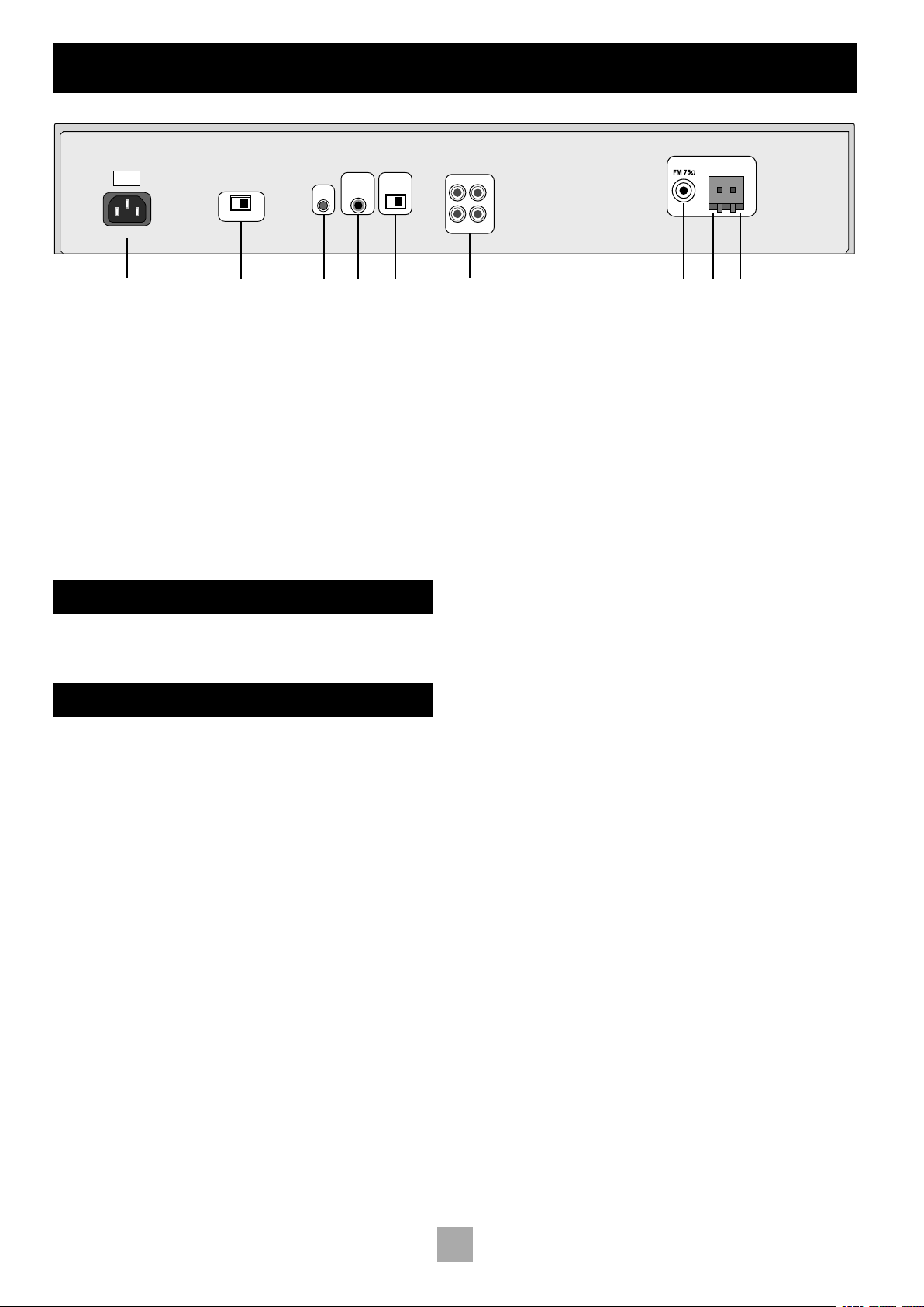
Installation
POWER INLET
230V
1
2 3 654
AERIALS
GND AM
7 8 9
AUDIO OUTPUTS
1 2
L
R
REMOTE
IN
115V 230V
12V
TRIGGER
IN
AM STEP
T31 REAR PANEL
Socket for IEC power inlet line
1
Voltage selector switch
2
Remote control input
3
Power On/Standby trigger in
4
AM step switch
5
POSITIONING THE UNIT
Always place the tuner on a level, firm surface.
SETTING UP THE TUNER
AM STEP SWITCH
The AM tuning ‘step size’ needs to be set according to your location.
This is done using the switch on the rear panel: set it to 10kHz if you
are in North America, or 9kHz anywhere else. This switch also ensures
correct reproduction of FM broadcasts for your location.
AM AERIAL
An AM aerial is required to receive AM/Medium Wave radio signals.
An external AM loop aerial is supplied as an accessory. This should be
attached to the AM Antenna inputs with one end connected to AM
and the other to Ground 8. It does not matter which way round
9
this aerial is fitted. Rotate the aerial to discover which position gives
the best reception.
In areas of weak reception or when the receiver is used inside a steel
framed building (such as an apartment building) you can use a wire
between 3 and 5 metres long to strengthen reception. Mount this high
up outside the building, if possible, and connect one end of this wire
to the AM antenna input 9 as well as the loop aerial supplied. DO
NOT DISCONNECT THE LOOP AERIAL.
5
Audio output phono sockets, two
6
pairs
FM coaxial plug
7
Ground socket (for AM loop aerial)
8
AM socket (for AM loop aerial)
9
FM AERIAL
An FM aerial is required to receive VHF radio signals. An external FM
ribbon aerial is supplied as an accessory.
For optimal FM radio reception a roof or loft mounted aerial is advised.
For your own safety it is recommended that a roof top aerial is fitted
by an experienced contractor. Your Arcam dealer should be able to put
you in contact with an aerial installer. A contractor will be able to tune
your aerial to the nearest FM transmitter. In an apartment building an
aerial system may already be installed. If this is the case you should have
sockets in your home marked FM or VHF (do not use those marked
TV).
The ‘T’ shaped wire aerial (dipole design) supplied should give
reasonably good reception. Mount this aerial as high up as possible on
a wall with the elements positioned horizontally. Try each usable wall
of the room to see which gives best reception. Use tacks or adhesive
tape to secure the aerial in a T-shape. The tacks should not come into
contact with the internal wire of the aerial.
Whether you decide to get an aerial professionally installed or opt
to use the supplied aerial it should be connected to the FM Antenna
input 7 on the rear of the unit.
For use in North America, use an F-type antenna connector; for Europe
and other areas, use a female Belling Lee-type coaxial connector.
4
Page 5

CONNECTING TO OTHER EQUIPMENT
INTERCONNECT CABLES
Interconnecting cables are not supplied with this tuner. We recommend
high quality cables as inferior quality cables will degrade the sound
quality of your system. Please contact your Arcam dealer for details
of suitable cables. Arcam do not recommend any particular type or
brand of interconnect cable.
CONNECTING YOUR TUNER TO YOUR AMPLIFIER
AUDIO OUTPUTS
Two pairs of identical outputs are provided.
Connect one set to your amplifier’s tuner input or any other line-level
input using suitable high quality interconnect cables. Ensure that the left
and right audio outputs from the tuner are connected to the same left
and right inputs on your amplifier.
The second set of audio outputs can be used to connect to a second
amplifier set up for ‘multiroom’ use, or routed to a tape recorder for
‘off air’ recording.
6
CUSTOM INSTALLATION FEATURES
The T31 has a number of useful features that make it ideal for a
custom installation, where the tuner is fully integrated with a specialist
control system or operated by a programmable remote control.
REMOTE CONTROL INPUT
A rear panel input that receives modulated carrier-based infrared (IR)
commands in RC5 format. The input is suitable for connection to a
simple IR eye or to an external controller.
Use of this socket disables the front panel IR eye.
TRIGGER INPUT
The trigger socket allows the tuner to be remotely switched in and
out of standby. The primary front panel POWER switch must be in,
‘on’, for this mode.
Apply a +12V DC voltage for ‘on’, the power indicator glows green; 0V
for ‘standby’, the power indicator glows red.
Note that use of this socket requires a 12V signal before the tuner can
be switched fully on.
4
3
INFRARED (IR) REMOTE COMMANDS
Engl i s h
CONNECTING TO A POWER SUPPLY
WRONG PLUG?
Check that the plug supplied with the unit fits your supply and that
your mains supply voltage agrees with the voltage setting switch (115V
or 230V) indicated on the rear panel of the unit 2.
If your mains supply voltage is different, switch the voltage selector
across using a small screwdriver.
MAINS LEAD
The appliance is normally supplied with a moulded mains plug already
fitted to the lead. If for any reason the plug needs to be removed, it
must be disposed of immediately and securely, as it is a potential shock
hazard when inserted into the mains socket. Should you require a new
mains lead, contact your Arcam dealer.
PLUGGING IN
Push the plug (IEC line socket) of the power cable supplied with the
unit into the POWER INLET socket 1 in the back of the unit. Make
sure it is pushed in firmly.
Put the plug on the other end of the cable into your power supply
socket and switch the socket on.
The T31 responds to a set of Philips RC-5 codes in addition to those
available on the supplied handset, which is kept simple for ease of
use.
Advanced programmable control devices, such as the Philips ‘Pronto’
and other system controllers, can be set up to use the additional codes.
Refer to the instructions for your programmable device for details.
A table of IR commands is provided on page 10 of this Handbook.
5
Page 6
7
Engl i s h
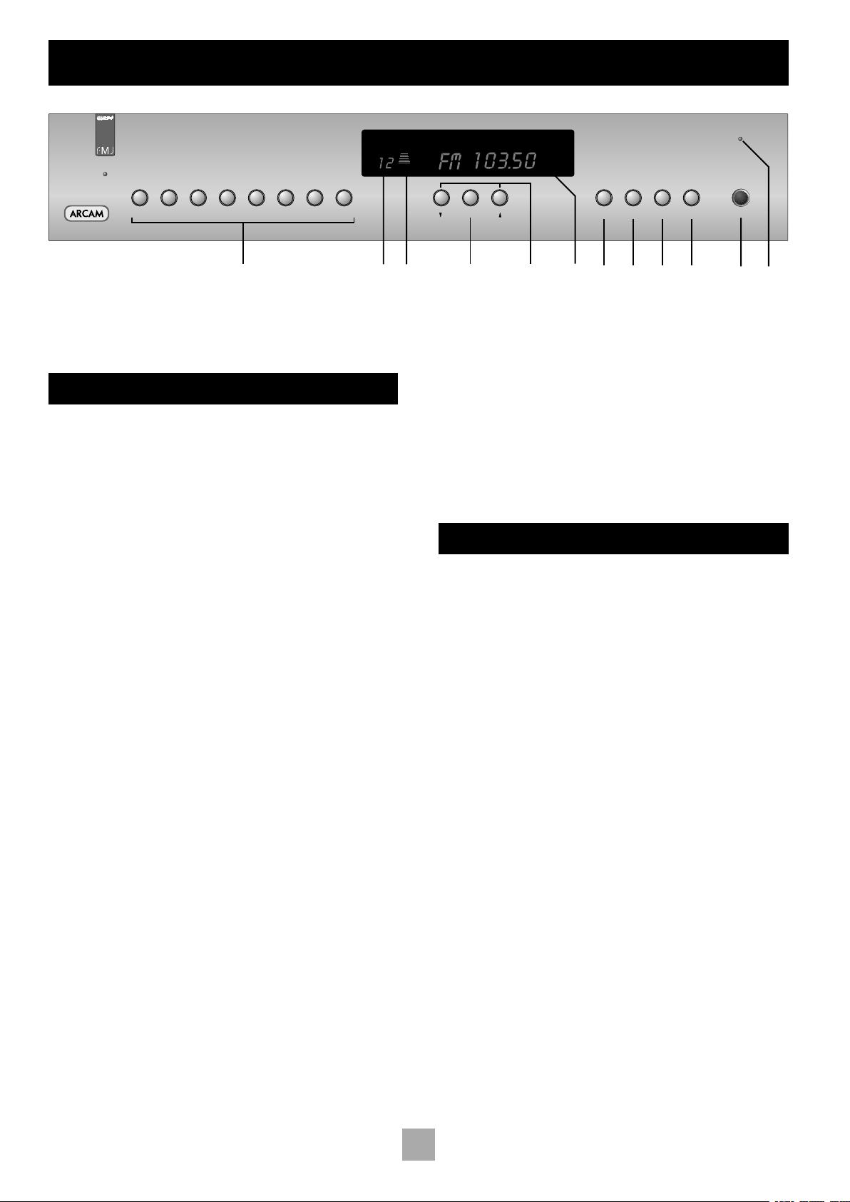
Using your tuner
bk
T31 AM/FM RDS TUNER
1 – 9
2 – 10 3 – 11 4 – 12 5 – 13 6 – 14 7 – 15 8 – 16 TUNING
BAND RDS MONO STORE POWER
1
432 58 9 bl bm
PRESET
MHz
FM MUTE
STEREO
TUNED
SIGNAL
6 7
FRONT PANEL CONTROLS
Preset Memory buttons
Directly select up to 32 preset stations (16 AM, 16 FM). Press briefly
for stations 1–8, press and hold for more than one second for stations
9–16.
BAND
Selects FM or AM frequency band. The appropriate letters appear on
the display.
RDS
Switches between RDS modes on FM if RDS is available. See the
section ‘RDS: Radio Data System’.
MONO
Selects mono or stereo output. Stereo is only available on FM radio
stations. If a weak station is received in stereo the background hiss can
be reduced (and in most cases eliminated) by selecting ‘MONO’.
In mono mode, FM muting is suppressed when tuning between
stations and the ‘FM MUTE’ indicator is switched off.
STORE
The STORE button allows you to assign radio stations to preset
numbers. See the instruction ‘Storing a preset’
Preset indicator
Indicates the number of the preset currently selected.
Signal strength
A seven-step indicator shows the strength of a tuned station. Good
FM reception and locking onto RDS data generally requires five or
more bars.
Tuning
Switches between Tune and Preset mode for the down/up buttons.
Preset mode is indicated by PRESET on the display.
Tune down/up
Used to either scroll through presets, or to tune up and down the
broadcast band, depending on the current mode. See ‘Tuning to a
station’ for more details.
Frequency/ RDS display
Indicates the frequency of the selected station in MHz (FM) or kHz
(AM); it also displays RDS information when present.
2
3
4
5
6
7
8
9
1
bk
POWER
Switches the mains power to the unit on or off.
Power indicator
This glows green to show that the unit is ready for use. The indicator
glows red in standby mode when the tuner is switched off via the
remote control, or configured in a custom installation.
bl
bm
OPERATION
The T31 radio tuner can be controlled from the front panel buttons or
from the remote control handset (see ‘Using the remote control’).
TUNING TO A STATION
Pressing the TUNING button toggles between the two tuning modes
of the unit – ‘Preset’ or ‘Tune’. The selected mode is briefly shown in
the display.
PRESET MODE
In Preset mode, press the 5 or 6 buttons on the front panel (or
< or > on the remote control handset) to cycle up and down the
preset stations.
See ‘Storing a preset’ and ‘Deleting unused presets’, below.
TUNE MODE
Automatic tuning:
Press the5 or 6 buttons on the front panel (or < or > on the
remote control handset) for longer than one second to engage
automatic tuning. The tuner searches for a radio station signal of
sufficient strength and stops. To skip to the next station, press one of
the buttons again. Automatic tuning is available for both the FM and
AM bands.
Manual tuning:
Tap the 5 or 6 buttons for manual tuning. This can be used for
tuning to a specific frequency. It is also useful if you are trying to
select a station that is too weak for the auto search mode.
Regardless of the mode used to tune your T31, when it is accurately
tuned to a station ‘TUNED’ lights up in the display.
6
Page 7

STORING A PRESET
ENTERING STATION NAMES MANUALLY
To store a preset, tune to the radio station you wish to store. Press
the STORE button: this causes ‘PRESET STORE’ to flash in the display.
Now select the preset number you wish to assign to the station using
the preset memory buttons or the 5 and 6 buttons on the front
panel. Press the STORE button again.
Once the preset is stored, the display reverts to show the station
name (if RDS information is transmitted) or its frequency.
To quit the memory function without storing a preset, leave the tuner
controls untouched for ten seconds. It is also possible to overwrite a
stored station by saving another in its place. There are thirty presets
available for FM use and sixteen for AM use.
Your presets are retained when the T31 is disconnected from the
mains supply.
DELETING AN UNUSED PRESET
Press the RDS and STORE buttons on the front panel, wait about three
seconds, then select the preset number you want to delete using the
and 6 buttons, followed by the RDS button.
5
The display briefly shows ‘DELETED’ and ‘– –’ is shown in place of the
preset number. You can reactivate a deleted preset number by storing
a station in the normal way.
Station names can be entered and saved for preset AM stations, and
for FM stations where RDS is not available. Station names can be up
to eight characters long.
First select the band and the preset station you wish to name. Then
press and hold the RDS button for more than two seconds. An
‘underscore’ line should appear blinking in the first position of the
frequency display area. Use the 5 and 6 buttons beneath the
display to scroll through the available alphabet, numbers and special
characters available until you reach your wanted letter or character.
Press the TUNING button to confirm that character. The ‘underscore’
line will then move to the next position. Repeat this process to enter
the required name. If you want to edit a character later, use the
TUNING button to step along and select it, then use the
keys as before to change it. When complete, press STORE to enter the
name into the preset memory.
5
and 6
Engl i s h
RDS: RADIO DATA SYSTEM
The Arcam T31 suppor ts RDS Programme Service and RDS Radio
Text on FM broadcasts.
When a station carrying RDS information is selected ‘RDS’ lights up in
the display and shortly afterwards the station’s RDS name (e.g. ‘BBC
R3’) is shown.
Press the RDS button to view any RDS text information (if a station
is not transmitting text information, the display briefly indicates ‘NO
TEXT’ and reverts to show the station name).
Press RDS again to display the station’s frequency.
Pressing RDS a third time returns you to a display of the station
name.
If the RDS button is pressed while tuned to a non-RDS station, the
display shows ‘NO NAME’ for three seconds before reverting to the
default display.
7
Page 8
9
Engl i s h
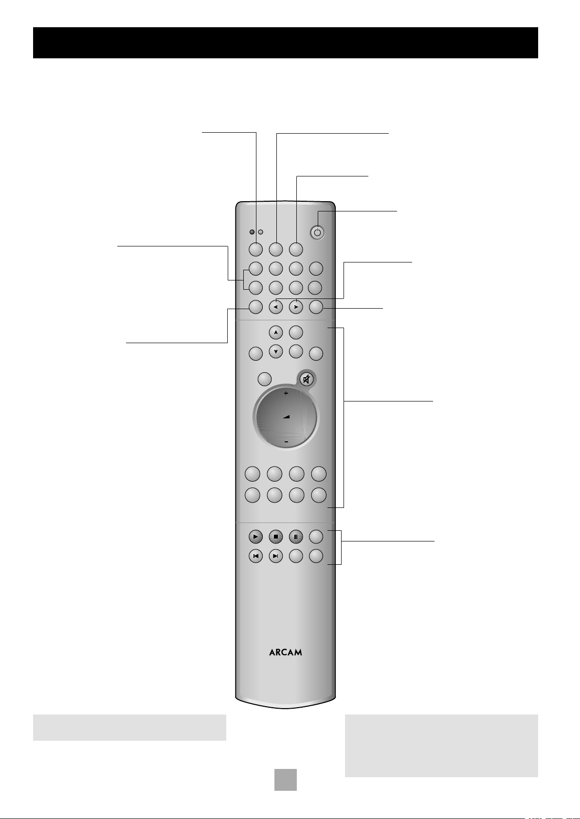
Using the CR-389 remote control
FM DAB
PROG DISP
RPT
MODE BAND
1–9 2–10 3–11
FM
DAB
SEL
TUNER
CR-389
CD
AMPLIFIER
VCRDVD TAPEAV
TUNERCDAU
XPHONO
ENTER
SP1
SP2
DISP
MENU DISP
4–12
5–13 6–14 7–15 8–16
Ensure that the FM mode is selected using the
FM/DAB toggle button. The FM LED above the FM/
DAB button is lit briefly when FM is selected.
Preset memory buttons
These buttons allow access to individual preset stations. To
select a preset press the corresponding keypad button. For
presets 9–16, press and hold the corresponding preset button
for one second. Use the Tune buttons to access FM memory
MODE (Tuning mode)
This button toggles between
PRESET and TUNE modes.
FM/DAB
presets 17 to 30.
MENU (RDS mode)
This button scrolls through RDS modes, when available.
DISP (Display)
This button allows you to dim or switch off the tuner display.
STANDBY
This button switches the tuner (and the amplifier if
appropriate) between ‘On’ and ‘Standby’. This function
does not apply Arcam CD players.
Tune buttons
These buttons enable you to scroll through the stored
station selections one at a time, or to tune up or down,
depending on the Tuning mode.
BAND
This button toggles between FM and AM.
Amplifier controls
These buttons offer basic control over Arcam amplifiers,
such as the FMJ A32.
CD player controls
These buttons offer basic control over Arcam CD players,
such as the FMJ CD23.
NOTE: DAB (Digital Audio Broadcast) refers to
Arcam DAB tuners such as model DT81.
NOTE: Remember to install the two AAA batteries
supplied before trying to use your remote control.
Do not place anything in front of the display area on
the tuner (where the IR receiver is located), or the
remote control may not work.
8
Page 9

Technical specications
T31 TUNER
FM Section
Tuning range 87.5 to 108.0MHz
Frequency steps 50kHz
Presets: total/direct access 30/16
Sensitivity (IHF) for 50dB S/N ratio typically 3µV
Alternate channel selectivity better than 60dB
Capture ratio 1.5dB
Frequency response 20Hz–15kHz ±1dB
Ultimate S/N ratio (CCIR) Mono better than –75dB
Stereo better than –70dB
Total harmonic distortion (96MHz reference, 22.5kHz deviation at 1kHz)
Mono better than 0.1%
Stereo better than 0.2%
Channel separation (1kHz) better than 40dB
Pilot tone suppression better than 60dB
Output level 700mV at 75kHz deviation
AM Section
Tuning range: 10kHz step; 530 to 1710 kHz
9kHz step; 531 to 1602 kHz
Presets 16
Usable sensitivity typically 30µV
IF rejection > 36dB
S/N ratio (30% mod., 50mV I/P) > 38dB
Total harmonic distortion (30% mod., 50mV I/P) < 3%
Output level 300mV at 70% modulation
Engl i s h
Control inputs
IR remote standard Philips RC-5, 36kHz carrier
IR in signal level 4–15V pk-pk
Trigger operating voltage 9–15V DC
Trigger in polarity tip positive
General
Output impedance 220Ω
Minimum recommended load 5kΩ
Power consumption 10VA
Size W x D x H 430 x 290 x 85mm
Weight net 3.8kg
Weight packed 6.0kg
Supplied accessories FM dipole aerial
AM loop aerial
mains lead
CR-389 remote control handset and batteries
E&OE
CONTINUAL IMPROVEMENT POLICY
Arcam has a policy of continual improvement for its products. This
means that designs and specifications are subject to change without
notice.
NOTE: All specification values are typical unless otherwise stated.
9
Page 10

11
Engl i s h
TABLE OF IR COMMANDS
Command Decimal code
Standby 17–124
On 17–123
Power toggle 17–12
AM/FM band toggle 17–50
AM band 17–52, 17–46
FM band 17–53, 17–45
Tune down (seek if >1second) 17–31
Tune up (seek if >1second) 17–30
Seek tune down 17–35
Seek tune up 17–34
RDS program 17–62
RDS text 17–63
RDS frequency 17–64
Scroll RDS mode 17–55, 17–61, 17–15
Display on 17–14
Display toggle 17–18
Stereo 17–39
Mono 17–54
Stereo/Mono toggle 17–38
Preset/tune mode toggle 17–37
Preset/tune up 17–32
Preset/tune down 17–33
Store 17–41
Mute on 17–119
Mute off 17–120
Mute toggle 17–13
Preset 1 to 8 (9 to 16 if >1second) 17–1 to 17–8
Preset 9 17–9
Preset 10 to 17 17–110 to 17–117
Preset 18 to 30 17–88 to 17–100
NOTE: The above codes are consistent with the Philips RC-5
standard.
10
Page 11

Guarantee
WORLDWIDE GUARANTEE
This entitles you to have the unit repaired free of charge, during the
first two years after purchase, at any authorised Arcam distributor
provided that it was originally purchased from an authorised Arcam
dealer or distributor. The manufacturer can take no responsibility for
defects arising from accident, misuse, abuse, wear and tear, neglect
or through unauthorised adjustment and/or repair, neither can they
accept responsibility for damage or loss occurring during transit to or
from the person claiming under the guarantee.
The warranty covers:
Parts and labour costs for two years from the purchase date. After two
years you must pay for both par ts and labour costs. The warranty
does not cover transportation costs at any time.
CLAIMS UNDER GUARANTEE
This equipment should be packed in the original packing and returned
to the dealer from whom it was purchased, or failing this, directly
to the Arcam distributor in the country of residence. It should be
sent carriage prepaid by a reputable carrier -– NOT by post. No
responsibility can be accepted for the unit whilst in transit to the
dealer or distributor and customers are therefore advised to insure
the unit against loss or damage whilst in transit.
For further details contact Arcam at:
Arcam Customer Support Department,
Pembroke Avenue, Waterbeach, CAMBRIDGE, CB5 9PB, England
Telephone: +44 (0)1223 203203
Fax: +44 (0)1223 863384
Email: support@arcam.co.uk
QUESTIONS?
Always contact your dealer in the first instance.
If your dealer is unable to answer any query regarding this or any other
Arcam product please contact your local distributor. A list of current
distributors can be found at www.arcam.co.uk. In the U.K., contact
Arcam Customer Support on 01223 203203 or write to us at the
above address and we will do our best to help you.
ON LINE REGISTRATION
You can register your Arcam product on line at:
www.arcam.co.uk/reg
Engl i s h
11
Page 12

Fr ança i s
13
Consignes de sécurité
RISQUE DE CHOC ELECTRIQUE
NE PAS OUVRIR
ATTENTION
CAUTION
RISK OF ELECTRIC
SHOCK DO NOT OPEN
ATTENTION : Pour éviter tout risque de choc électrique,
ne pas enlever le couvercle (ou le panneau arrière). Aucune
intervention n’est possible pour l’utilisateur. Pour le service,
voir un personnel qualifié.
AVERTISSEMENT : Pour éviter tout risque d’incendie ou
de choc électrique, ne pas exposer l’appareil à la pluie ou
à l’humidité.
Le symbole d’un éclair dans un triangle a pour objet d’avertir l’utilisateur
de la présence à l’intérieur du boîtier de l’appareil de “tension électrique
dangereuse” non-isolée et de force suffisante à constituer un risque de
choc électrique.
Le point d’exclamation dans un triangle a pour objet d’avertir l’utilisateur
de la présence de renseignements importants concernant l’utilisation et
la maintenance (le service après vente) dans la documentation fournie
avec le produit.
ATTENTION : Au Canada et aux États-Unis, pour éviter
tout risque de choc électrique, alignez la lame large de la
fiche secteur avec la fente large de la prise murale, puis
enfoncez la fiche complètement.
CONSEILS DE SÉCURITÉ IMPORTANTS
Cet appareil a été conçu et fabriqué conformément aux normes de
qualité et de sécurité les plus strictes. Vous devez cependant observer
les précautions suivantes lors de son installation et de son utilisation.
1. Avertissements et consignes
Il est conseillé de lire les consignes de sécurité et d’utilisation avant
de mettre cet appareil en marche. Conservez ce manuel pour
pouvoir vous y référer par la suite et respectez scrupuleusement les
avertissements figurant dans ce manuel ou sur l’appareil lui-même.
2. Eau et humidité
L’installation d’un appareil électrique à proximité d’une source d’eau
présente de sérieux risques. Il ne faut pas utiliser l’appareil à proximité
d’un point d’eau : près d’une baignoire, d’un lavabo, d’un évier, dans une
cave humide ou à côté d’une piscine, etc.
3. Chute d’objets ou infiltration de liquides
Veillez à ne pas laisser tomber d’objets ni faire couler de liquides
à travers l’une des ouvertures du boîtier. Ne posez pas d’objet
contenant du liquide sur l’appareil.
4. Ventilation
Évitez de placer l’appareil sur un lit, un canapé, un tapis ou une surface
similaire instable, ou dans une bibliothèque ou un meuble fermé, ce
qui risquerait d’empêcher une ventilation correcte. Pour permettre
une ventilation appropriée, il est conseillé de prévoir au minimum un
espace de 5 cm de chaque côté et au-dessus de l’appareil.
5. Exposition à la chaleur
Ne placez pas l’appareil près d’une flamme nue ou d’un dispositif
produisant de la chaleur, tel un radiateur, un poêle ou autre appareil (y
compris les amplificateurs).
6. Conditions climatiques
L’appareil est conçu pour fonctionner dans des climats modérés.
7. Étagères et supports
Utilisez uniquement des étagères ou des supports pour appareils
audio. Si l’appareil est posé sur un support mobile, déplacez celui-ci
avec précaution, pour éviter tout risque de chute.
8. Nettoyage
Débranchez l’appareil du secteur avant de le nettoyer.
Pour le nettoyage, utilisez un chiffon doux, humide et non pelucheux.
N’utilisez pas de diluant pour peinture ou de solvant chimique.
L’emploi d’aérosols ou de produits de nettoyage pour meubles est
déconseillé, car le passage d’un chiffon humide risquerait de laisser des
marques blanches indélébiles.
9. Alimentation secteur
Branchez l’appareil uniquement sur une alimentation secteur du type
mentionné dans le manuel d’utilisation ou indiqué sur l’appareil luimême.
10. Protection des cordons secteur
Veillez à ce que les cordons secteur ne se trouvent pas dans un lieu de
passage ou pincés par un objet quelconque. Prêtez particulièrement
attention aux cordons et fiches secteur à leurs points de sortie de
l’appareil.
11. Mise à la terre
Assurez-vous que l’appareil est correctement mis à la terre.
12. Câbles haute tension
Évitez de monter une antenne extérieure à proximité de câbles haute
tension.
13. Périodes de non-utilisation
Si l’appareil possède une fonction de mise en veille, un courant faible
continuera de circuler lorsqu’il est réglé sur ce mode. Débranchez
le cordon secteur de la prise murale si l’appareil doit rester inutilisé
pendant une période prolongée.
14. Odeur suspecte
Arrêtez et débranchez immédiatement l’appareil en cas de fumée ou
d’odeur anormale. Contactez immédiatement votre revendeur.
15. Service
Ne tentez pas d’effectuer d’autres opérations que celles mentionnées
dans ce manuel. Toute autre intervention doit être effectuée par un
personnel qualifié.
16. Entretien par un personnel qualifié
L’appareil doit être entretenu par du personnel qualifié lorsque :
A. la fiche ou le cordon secteur a été endommagé,
B. des objets sont tombés ou du liquide a coulé dans l’appareil,
C. l’appareil a été exposé à la pluie,
D. l’appareil ne semble pas fonctionner normalement ou présente
des altérations dans son fonctionnement,
E. l’appareil est tombé ou le boîtier a été endommagé.
CONFORMITÉ AUX NORMES DE SÉCURITÉ
Cet appareil est conçu pour répondre à la norme internationale de
sécurité électrique IEC 60065.
12
Page 13

Utilisation de ce manuel
Ce manuel est conçu pour vous fournir toutes les informations dont
vous avez besoin pour installer, brancher, régler et utiliser le tuner
Arcam T31. La télécommande CR-389 fournie avec cet appareil est
aussi décrite.
SÉCURITÉ
Les consignes de sécurité figurent à la page 12 de ce manuel.
Bien que bon nombre d’entre elles fassent appel au simple bon sens,
il est conseillé de les lire pour votre propre sécurité et pour éviter
d’endommager l’appareil.
INTERFÉRENCE RADIO
Tous les produits Arcam sont conçus selon des normes très strictes de
compatibilité électromagnétique.
Cependant, les lecteurs de CD et de DVD génèrent de l’énergie à
fréquence radio qui peut, dans certains cas, perturber la réception de
radio FM ou PO/GO. Si c’est le cas, éteignez le lecteur ou éloignez
autant que possible celui-ci et ses câbles de raccordement du tuner
et de ses antennes. Brancher le cordon secteur du lecteur et celui du
tuner ou de l’amplificateur sur des prises murales différentes peut aussi
aider à réduire l’interférence.
PAYS DE LA CE
Ce produit est conçu en conformité avec la directive 89/336/EEC.
TABLE DES MATIÈRES
Consignes de sécurité ................................................................ 12
Conseils de sécurité importants................................................. 12
Conformité aux normes de sécurité........................................12
Utilisation de ce manuel............................................................. 13
Sécurité...................................................................................................... 13
Mise en place de l’appareil............................................................. 14
Réglage du tuner.................................................................................. 14
Installation .....................................................................................14
Raccordement à d’autres appareils........................................... 15
Raccordement du tuner à l’amplicateur...............................15
Raccordement secteur .....................................................................15
Installation personnalisée ................................................................15
Commandes à distance infrarouges (IR)................................ 15
Commandes sur la face avant...................................................... 16
Utilisation du tuner ..................................................................... 16
Emploi........................................................................................................ 16
Mémorisation d’une station...........................................................17
RDS : Radio Data System ............................................................... 17
Entrée manuelle des noms de station..................................... 17
Utilisation de la télécommande................................................18
Spécications techniques ...........................................................19
Table des commandes IR ................................................................ 20
Garantie......................................................................................... 21
Enregistrement sur Internet........................................................... 21
Fr ança i s
ÉTATS-UNIS
Ce produit est conforme aux normes de la FCC. Si l’appareil perturbe
la réception de radio ou de télévision, ce qui peut être vérifié en
mettant l’appareil hors/sous tension, il faut prendre les mesures
suivantes. Changez l’orientation de l’antenne ou positionnez le câble
d’antenne du tuner aussi loin que possible de cet appareil et de ses
câbles de raccordement. Changez de place le tuner par rapport à cet
appareil. Branchez les cordons secteurs du tuner et de cet appareil à
des prises secteur différentes. Si le problème persiste, contactez votre
revendeur Arcam ou le Service Clientèle Arcam au +44 (0)1223
203203.
13
Page 14

Fr ança i s
15
Installation
POWER INLET
230V
1
2 3 654
AERIALS
GND AM
7 8 9
AUDIO OUTPUTS
1 2
L
R
REMOTE
IN
115V 230V
12V
TRIGGER
IN
AM STEP
PANNEAU ARRIÈRE DU T31
1
2
3
4
5
MISE EN PLACE DE L’APPAREIL
Placez toujours le tuner sur une surface plane et stable.
RÉGLAGE DU TUNER
SÉLECTEUR DE PAS PO
Il faut sélectionner le pas du réglage de la fréquence PO compatible
avec les émetteurs de votre région. Au moyen du commutateur sur
le panneau arrière, réglez le pas à 10 kHz si vous êtes en Amérique
du nord, à 9 kHz partout ailleurs. Ce commutateur assure aussi la
reproduction correcte des émissions FM dans votre région.
ANTENNE PO
Pour la réception de signaux radio PO, une antenne adéquate est
nécessaire.
Une antenne boucle PO externe est fournie comme accessoire. Il
faut la fixer aux entrées antenne PO, une extrémité connectée à la
prise PO 9 et l’autre à la prise de terre 8. Le sens du branchement
est sans importance. Tournez l’antenne pour obtenir la meilleure
réception possible.
Si la réception est faible ou si le tuner est utilisé à l’intérieur d’un
bâtiment à structure métallique (un immeuble, par exemple), vous
pouvez utiliser un fil long de 3 à 5 mètres pour améliorer la réception.
Il faut installer ce fil le plus haut possible à l’extérieur du bâtiment
et connecter une des extrémités à la prise antenne PO 9. NE
DÉBRANCHEZ PAS L’ANTENNE BOUCLE.
ANTENNE FM
Pour la réception des signaux radio FM, une antenne adéquate est
nécessaire. Une antenne FM externe est fournie comme accessoire.
5
Prise secteur IEC
Sélecteur de tension secteur
Entrée télécommande
Entrée bascule marche/veille
Sélecteur de pas PO
Pour une réception FM optimale, il est conseillé d’installer une
antenne sur le toit ou dans le grenier. Pour votre sécurité, faites appel
à un installateur professionnel. Votre revendeur Arcam peut vous en
indiquer un. L’installateur réglera votre antenne sur l’émetteur FM le
plus proche. Dans certains immeubles une antenne est déjà installée.
Dans ce cas, il y aura chez vous des prises antenne marquées FM ou
VHF (ne pas utiliser une prise marquée TV).
L’antenne en forme de “T” fournie devrait donner d’assez bons
résultats. Installez celle-ci aussi haut que possible et positionnez les
deux éléments à l’horizontal. Pour obtenir la meilleure réception,
essayez l’antenne sur chaque mur de la pièce où il est possible de
l’installer. Fixez-la au moyen de punaises ou de bande adhésive afin
de préserver sa forme en “T”. Évitez que les punaises touchent les
conducteurs de l’antenne.
Quel que soit le type d’antenne choisie, il faut la connecter à l’entrée
antenne FM 7 sur le panneau arrière de l’appareil.
En Amérique du nord, utilisez un connecteur d’antenne type F ; en
Europe et ailleurs, utilisez un connecteur coaxial femelle type BellingLee.
14
Prises de sortie audio, deux paires
6
Fiche coaxiale FM
7
Prise de terre (pour antenne boucle
8
PO)
Prise PO (pour antenne boucle PO)
9
Page 15

RACCORDEMENT À D’AUTRES APPAREILS
CÂBLES DE RACCORDEMENT
Les câbles de raccordement ne sont pas fournis avec ce tuner. Nous
recommandons l’utilisation de câbles de raccordement de qualité afin
de ne pas nuire à la qualité sonore de votre système. Veuillez contacter
votre revendeur Arcam pour en savoir plus.
RACCORDEMENT DU TUNER À L’AMPLIFICATEUR
Sorties audio
Il y a deux paires de prises de sortie identiques.
Utilisez des câbles de raccordement de qualité pour relier une de ces
paires à l’entrée tuner de l’amplificateur ou à toute autre entrée de
niveau ligne. Assurez-vous que les sor ties gauche et droite du tuner
sont bien reliées aux entrées gauche et droite de l’amplificateur.
La deuxième paire de sor ties audio permet le raccordement à
un deuxième amplificateur dans un système “multi-room” ou à un
magnétophone pour l’enregistrement des émissions radio.
6
INSTALLATION PERSONNALISÉE
Le T31 possède plusieurs fonctions qui facilitent son utilisation au
sein d’une installation personnalisée où le tuner est commandé
par un système de contrôle spécifique ou par une télécommande
programmable.
Entrée télécommande
Cette entrée sur le panneau arrière peut recevoir des commandes
infrarouges (IR) sur porteuse modulée au standard RC5. Elle peut
être reliée à un simple capteur IR ou à un système de commande
externe.
L’utilisation de cette entrée met hors circuit le capteur IR sur la face
avant.
Entrée bascule
Cette entrée permet de télécommander la mise en marche/en veille
du tuner. Pour qu’elle fonctionne, la touche POWER sur la face avant
doit être en position “marche” (enfoncée).
La présence d’une tension de +12 V CC met le tuner en marche et
le témoin vert s’allume. Un signal de 0 V met le tuner en veille et le
témoin passe au rouge.
Notez que l’utilisation de cette entrée exige la présence d’un signal de
12 V pour que le tuner puisse être mis en marche.
4
3
Fr ança i s
RACCORDEMENT SECTEUR
LA FICHE SECTEUR EST-ELLE LA BONNE ?
Assurez-vous que la fiche fournie avec l’appareil correspond à votre
prise murale et que la tension secteur correspond au réglage (115 V
ou 230 V) indiqué sur le panneau arrière de l’appareil 2.
Si votre tension secteur est différente, changez la position du sélecteur
de tension à l’aide d’un petit tournevis.
CORDON SECTEUR
Normalement, l’appareil est livré avec une fiche secteur moulée
montée sur le cordon. Si vous devez, pour une raison quelconque,
retirer la fiche, jetez-la immédiatement car son branchement sur
une prise murale risquerait de provoquer une électrocution. Si vous
avez besoin d’un nouveau cordon secteur, contactez votre revendeur
Arcam.
BRANCHEMENT
Enfoncez la fiche (prise IEC) du cordon secteur fourni dans la prise
secteur 1 située à l’arrière de l’appareil. Vérifiez qu’elle est enfoncée
complètement.
Introduisez la fiche située à l’autre extrémité du cordon dans votre
prise murale.
COMMANDES À DISTANCE INFRAROUGES (IR)
En plus des codes générés par la télécommande fournie, conçue
pour une utilisation simple et facile, le T31 reconnaît des codes Philips
RC-5.
Les télécommandes programmables, telles le “Pronto” de Philips et
d’autres systèmes de commande, peuvent être réglées pour l’utilisation
de codes additionnels. Pour plus de détails, consultez le mode d’emploi
de votre télécommande programmable.
Une table de commandes IR se trouve page 20 de ce manuel.
15
Page 16

Utilisation du tuner
bk
T31 AM/FM RDS TUNER
1 – 9
2 – 10 3 – 11 4 – 12 5 – 13 6 – 14 7 – 15 8 – 16 TUNING
BAND RDS MONO STORE POWER
1
432 58 9 bl bm
PRESET
MHz
FM MUTE
STEREO
TUNED
SIGNAL
6 7
COMMANDES SUR LA FACE AVANT
Touches mémoires de présélection
Sélectionnent directement jusqu’à 32 stations mémorisées (16 FM,
16 PO). Appuyez brièvement pour les stations 1–8 ; pour les stations
9–16, appuyez plus d’une seconde.
BAND
Sélectionne la gamme FM ou PO. La gamme choisie s’affiche.
RDS
Commute entre les modes RDS en FM, si le RDS est disponible. Voir
“RDS : Radio Data System”.
MONO
Sélectionne la sortie mono ou stéréo. La stéréo n’est disponible
qu’avec des stations FM. Pour réduire (et, dans la plupart des cas,
éliminer) le bruit de fond présent avec une station stéréo faible,
sélectionnez “MONO”.
En mode mono, le muting FM est supprimé entre les stations pendant
la recherche, et l’indicateur “FM MUTE” est éteint.
STORE
Cette touche permet d’affecter un numéro de présélection à une
station. Voir “Mémorisation d’une présélection”.
Indicateur de présélection
Affiche le numéro de la présélection choisie.
Niveau de signal
Un indicateur à sept barres montre le niveau de signal de la station
captée. En FM, il faut normalement cinq barres ou plus pour une
bonne réception et pour recevoir les données RDS.
TUNING
Commute le mode de fonctionnement des touches haut/bas entre
Recherche et Présélection. En mode Présélection, “PRESET” s’affiche.
Recherche vers le haut/vers le bas
Servent, en fonction du mode choisi, à faire défiler les présélections ou
à rechercher une fréquence. Voir “Recherche d’une station”.
Affichage fréquence / RDS
Indique la fréquence de la station sélectionnée en MHz (FM) ou en
kHz (PO). Affiche aussi les données RDS, lorsqu’elles sont présentes.
2
3
4
5
6
7
8
bk
9
1
POWER
Permet de mettre l’appareil sous/hors tension.
Témoin d’alimentation bm
Celui-ci est vert lorsque l’appareil est prêt à fonctionner. Il est rouge
lorsque le tuner est en veille (arrêté au moyen de la télécommande)
ou utilisé dans une installation personnalisée.
bl
EMPLOI
On peut utiliser le tuner T31 en se servant des touches sur la face avant
ou de la télécommande (voir “Utilisation de la télécommande”).
RECHERCHE D’UNE STATION
Appuyez sur la touche TUNING pour commuter entre les deux
modes de recherche de l’appareil, Présélection et Recherche. Le mode
sélectionné s’affiche brièvement.
MODE PRÉSÉLECTION
En mode Présélection, appuyez sur les touches 5 et 6sur la
face avant (ou sur < ou > sur la télécommande) pour passer d’une
présélection à une autre.
Voir “Mémorisation d’une station” et “Suppression d’une présélection”
ci-dessous.
MODE RECHERCHE
Recherche automatique :
Pour déclencher la recherche automatique, appuyez sur les touches
et 6sur la face avant (ou sur < ou > sur la télécommande) plus
5
d’une seconde. Le tuner recherche un signal de station suffisamment
fort et s’arrête. Pour passer à la station suivante, appuyez de nouveau
sur une de ces touches. La recherche automatique fonctionne sur les
deux gammes FM et PO.
Recherche manuelle :
Pour rechercher une fréquence manuellement, appuyez sur les touches
et 6. On peut ainsi obtenir une fréquence donnée, ce qui est
5
utile en particulier pour sélectionner une station trop faible pour être
détectée par la recherche automatique.
Avec l’un ou l’autre mode de recherche, quand le T31 est réglé sur une
station de façon précise, l’indicateur “TUNED” s’affiche.
16
Page 17

MÉMORISATION D’UNE STATION
ENTRÉE MANUELLE DES NOMS DE STATION
Pour mémoriser une station, réglez le tuner sur la station en question.
Appuyez sur la touche STORE : “PRESET STORE” clignote sur
l’affichage. Ensuite, au moyen des touches mémoires de présélection
ou des touches 5 et 6 sur la face avant, sélectionnez le numéro de
présélection que vous voulez affecter à la station. Appuyez de nouveau
sur STORE.
Une fois la station mémorisée, le nom de la station (si les données
RDS sont disponibles) ou sa fréquence s’affiche.
Pour quitter la fonction mémoire sans mémoriser une présélection,
attendez dix secondes sans appuyer sur une touche. Pour changer
une station déjà mémorisée, il suffit d’en mémoriser une autre à sa
place. Il y a trente présélections pour la gamme FM et seize pour la
gamme PO.
Lorsque le T31 est débranché du secteur, les mémoires sont
maintenues.
SUPPRESSION D’UNE PRÉSÉLECTION
Appuyez sur les touches RDS et STORE sur la face avant et attendez
environ trois secondes. Au moyen des touches 5 et 6, sélectionnez
la présélection que vous voulez supprimer, puis appuyez sur la touche
RDS.
”DELETED” s’affiche brièvement et “– –” remplace le numéro de
présélection. Pour réactiver une présélection supprimée, il suffit de
mémoriser une station comme indiqué ci-dessus.
Les noms des stations peuvent être entrés et mémorisés pour des
stations PO et pour des stations FM non-RDS. Un nom de station peut
comporter jusqu’à huit caractères.
D’abord, sélectionnez la gamme de fréquence et la station mémorisée
à laquelle vous voulez associer un nom. Puis, appuyez sur la touche
RDS plus de deux secondes. Un trait de “soulignement” s’affiche à la
place de la fréquence en clignotant. Utilisez les touches5 et 6pour
parcourir les lettres, chiffres et caractères spéciaux disponibles. Pour
confirmer le choix d’un caractère, appuyez sur la touche TUNING. Le
trait de “soulignement” passera à la position suivante. Pour compléter
le nom, répétez cette procédure. Si vous voulez modifier un caractère
plus tard, utilisez la touche TUNING pour atteindre le caractère en
question, puis utilisez les touches5 et 6pour le modifier. Pour
entrer le nom dans la mémoire de présélection, appuyez sur la touche
STORE.
Fr ança i s
RDS : RADIO DATA SYSTEM
Le tuner Arcam T31 prend en charge le Service Programme RDS et le
Texte Radio RDS des émissions FM.
Lorsqu’une station émetteuse de données RDS est sélectionnée,
“RDS” s’affiche et le nom RDS de la station (par exemple, “BBC R3”)
s’affiche ensuite.
Pour afficher des données texte, appuyez sur la touche RDS (si la
station n’émet pas de données texte, “NO TEXT” s’affiche brièvement,
puis le nom de la station réapparaît.)
Pour afficher la fréquence de la station, appuyez encore sur RDS.
Pour afficher le nom de la station de nouveau, appuyez une troisième
fois sur RDS.
Si vous appuyez sur la touche RDS lorsqu’il s’agit d’une station non-
RDS, “NO NAME” s’affiche pendant trois secondes, puis l’affichage
revient à son état initial.
17
Page 18

Fr ança i s
19
Utilisation de la télécommande
FM DAB
PROG DISP
RPT
MODE BAND
1–9 2–10 3–11
FM
DAB
SEL
TUNER
CR-389
CD
AMPLIFIER
VCRDVD TAPEAV
TUNERCDAU
XPHONO
ENTER
SP1
SP2
DISP
MENU DISP
4–12
5–13 6–14 7–15 8–16
Utilisez la touche FM/DAB pour vous assurer que le
mode FM est sélectionné. Le témoin FM au-dessus de la
touche FM/DAB s’allume brièvement lorsque le mode
Touches mémoires de présélection
Ces touches permettent d’accéder directement aux stations
mémorisées. Pour sélectionner une mémoire, appuyez sur la
touche correspondante. Pour les mémoires 9–16, appuyez sur la
touche correspondante pendant une seconde. Pour accéder aux
mémoires FM 17 à 30, utilisez les touches Recherche.
MODE (mode recherche)
Cette touche commute entre les
modes Présélection et Recherche.
FM/DAB
FM est sélectionné.
MENU (RDS mode)
This button scrolls through RDS modes, when available.
DISP (“Display” : affichage)
Cette touche permet de réduire l’intensité de l’affichage ou de l’arrêter.
VEILLE
Cette touche commute le tuner (et l’amplificateur, le cas
échéant) entre “marche” et “veille”.
Touches recherche
En fonction du mode Recherche choisi, ces touches
permettent de faire défiler les stations mémorisées une
à une ou de rechercher une fréquence vers le haut ou
vers le bas.
BAND
Cette touche permet de commuter entre FM et PO.
Commandes amplificateur
Ces touches correspondent aux commandes de base des
amplificateurs Arcam, tel le FMJ A32.
Commandes lecteur de CD
Ces touches correspondent aux commandes de base des
lecteurs de CD Arcam, tel le FMJ CD23.
REMARQUE : DAB (Digital Audio Broadcast) fait
référence aux tuners DAB Arcam, tel le modèle DT81.
18
REMARQUE : Avant d’utiliser la télécommande,
pensez à installer les deux piles AAA fournies.
Ne placez rien devant l’affichage du tuner (où se situe
le récepteur infrarouge). Sinon, la télécommande risque
de ne pas fonctionner.
Page 19

Spécications techniques
TUNER T31
Section FM
Gamme des fréquences 87,5 à 108,0 MHz
Résolution 50 kHz
Présélections : total/accès direct 30/16
Sensibilité (IHF) pour rapport S/B 50 dB 3 µV typiquement
Sélectivité canal adjacent meilleure que 60 dB
Rapport de captage 1,5 dB
Réponse en fréquence 20 Hz - 15 kHz ±1 dB
Rapport signal/bruit efcace (CCIR) Mono meilleur que -75 dB
Stéréo meilleur que -70 dB
Distorsion harmonique totale (référence 96 MHz, déviation 22,5 kHz à 1 kHz)
Mono meilleure que 0,1 %
Stéréo meilleure que 0,2 %
Séparation des canaux (1 kHz) meilleure que 40 dB
Suppression du pilote meilleure que 60 dB
Niveau de sortie 700 mV (déviation 75 Hz)
Section PO
Gamme des fréquences :
pas de 10 kHz 530 à 1710 kHz
pas de 9 kHz 531 à 1602 kHz
Présélections 16
Sensibilité utilisable 30 µV typiquement
Rejet IF > 36 dB
Rapport S/B (mod. 30 %, 50 mV I/P) > 38 dB
Distorsion harmonique totale (mod. 30 %, 50 mV I/P) < 3 %
Niveau de sortie 300 mV (modulation 70 %)
Fr ança i s
Entrées commandes
Standard télécommande IR Philips RC-5, porteuse 36 kHz
Niveau du signal entrée IR 4 – 15 V p-p
Tension fonctionnement bascule 9 – 15 V CC
Polarité entrée bascule bout positif
Divers
Impédance de sortie 220 Ω
Charge minimum recommandée 5 kΩ
Consommation 10 VA
Dimensions L x P x H 430 x 290 x 85 mm
Poids net 3,8 kg
Poids avec emballage 6,0 kg
Accessoires fournis antenne dipôle FM
antenne boucle PO
cordon secteur
télécommande CR-389 avec piles
Sauf erreurs ou omissions.
POLITIQUE D’AMÉLIORATION CONSTANTE
Arcam améliore continuellement ses produits. Aussi, les designs et les
spécifications peuvent-ils faire l’objet de modifications sans préavis.
REMARQUE : Sauf mention contraire, toutes les valeurs
spécifiées sont des valeurs types.
19
Page 20

Fr ança i s
21
TABLE DES COMMANDES IR
Commande Code décimal
Veille 17–124
Marche 17–123
Commutateur marche/arrêt 17–12
Commutateur PO/FM 17–50
Gamme PO 17–52, 17–46
Gamme FM 17–53, 17–45
Recherche vers le bas (auto. si >1 seconde) 17–31
Recherche vers le haut (auto. si >1 seconde) 17–30
Recherche auto. vers le bas 17–35
Recherche auto. vers le haut 17–34
Programme RDS 17–62
Texte RDS 17–63
Fréquence RDS 17–64
Mode RDS délement 17–55, 17–61, 17–15
Afchage : marche 17–14
Commutateur afchage 17–18
Stéréo 17–39
Mono 17–54
Commutateur Stéréo/Mono 17–38
Commutateur mode Présélection/Recherche 17–37
Mémoire/recherche vers le haut 17–32
Mémoire/recherche vers le bas 17–33
Mémoriser 17–41
Muting : marche 17–119
Muting : arrêt 17–120
Commutateur du muting 17–13
Présélections 1 à 8 (9 à 16 si >1 seconde) 17–1 à 17–8
Présélection 9 17–9
Présélections 10 à 17 17–110 à 17–117
Présélections 18 à 30 17–88 à 17–100
REMARQUE : Les codes ci-dessus sont conformes au standard
Philips RC-5.
20
Page 21

Garantie
GARANTIE MONDIALE
Cette garantie vous donne le droit de faire réparer gratuitement
l’appareil chez un distributeur Arcam agréé durant les deux premières
années suivant l’achat, à condition que l’appareil ait, à l’origine, été
acheté chez un revendeur ou un distributeur Arcam agréé. Le fabricant
ne peut être tenu responsable en cas de défauts dus à un accident,
une mauvaise utilisation, une utilisation intensive, une usure normale,
une négligence, ou un réglage et/ou une réparation non autorisés. Il ne
peut en outre être tenu responsable pour tout dommage ou toute
perte survenu pendant le transport du matériel sous garantie.
Couverture de la garantie
La garantie couvre le coût des pièces et de la main d’œuvre pendant
deux ans à compter de la date d’achat. Après deux ans, ces frais
incombent au client. La garantie ne couvre jamais les frais de
transport.
RÉCLAMATIONS AU TITRE DE LA GARANTIE
L’appareil doit être renvoyé dans son emballage d’origine au revendeur
auprès duquel il a été acheté ou directement au distributeur Arcam du
pays de résidence du client.
Il doit être envoyé en port prépayé par l’intermédiaire d’un
transporteur fiable – jamais par la poste. Aucune responsabilité n’est
acceptée pendant le transport de l’appareil au titre de la garantie ;
aussi, est-il conseillé aux clients d’assurer l’appareil contre les pertes et
les dommages subis en transit.
Pour tout renseignement complémentaire, veuillez contacter Arcam :
Arcam Customer Support Department,
Pembroke Avenue, Waterbeach, CAMBRIDGE,
CB5 9PB, Grande Bretagne
Téléphone : +44 (0)1223 203203
Télécopie : +44 (0)1223 863384
Email: support@arcam.co.uk
QUESTIONS ?
Si votre revendeur ne peut pas répondre aux questions concernant
cet appareil ou tout autre produit Arcam, veuillez contacter votre
distributeur local. Vous trouverez une liste des distributeurs actuels
à www.arcam.co.uk. En Grande Bretagne, veuillez contacter le
Service Clientèle Arcam au 01223 203203 ou écrire à l’adresse cidessus, pour que nous puissions traiter votre problème au mieux.
ENREGISTREMENT SUR INTERNET
Vous pouvez enregistrer votre produit Arcam à l’adresse suivante :
www.arcam.co.uk/reg
Fr ança i s
21
Page 22

Deut s c h
23
Sicherheitsrichtlinien
RISQUE DE CHOC ELECTRIQUE
NE PAS OUVRIR
ATTENTION
CAUTION
RISK OF ELECTRIC
SHOCK DO NOT OPEN
ACHTUNG: Um das Risiko eines Elektroschocks zu
minimieren, sollten Sie die Abdeckung (Rückseite) nicht
entfernen. Die Bauteile im Gerät können vom Benutzer
nicht gewartet werden. Überlassen Sie die Wartung des
Gerätes einem Fachmann.
WARNUNG: Um das Risiko von Brand oder Elektroschock
zu reduzieren, sollten Sie dieses Gerät weder Regen noch
Feuchtigkeit aussetzen.
Das Blitzsymbol in einem Dreieck weist den Anwender auf eine nicht
isolierte „gefährliche Spannungsquelle“ im Gehäuse des Gerätes hin, die
stark genug sein kann, um einen Stromschlag auszulösen.
Das Ausrufezeichen in einem gleichschenkligen Dreieck weist
den Anwender auf wichtige Anweisungen zum Betrieb und zur
Instandhaltung (Wartung) in der Dokumentation hin.
WICHTIGE SICHERHEITSANWEISUNGEN
Dieses Gerät wurde unter Berücksichtigung strikter Qualitäts- und
Sicherheitsbestimmungen entworfen und gefertigt. Sie sollten jedoch
bei der Installation und dem Betrieb folgende Vorsichtsmaßnahmen
treffen:
1. Beachten Sie die Warnungen und Anweisungen
Vor der Inbetriebnahme dieses Gerätes sollten Sie die entsprechenden
Sicherheits- und Betriebsanweisungen lesen. Heben Sie dieses
Handbuch gut auf, und beachten Sie die enthaltenen Warnungen
sowie die Hinweise auf dem Gerät.
2. Wasser und Feuchtigkeit
Das Betreiben von elektrischen Geräten in der Nähe von Wasser
kann gefährlich sein. Verwenden Sie das Gerät nicht in einer feuchten
Umgebung (z.B. in der Nähe von Badewannen, Waschbecken,
Swimming Pools oder in einem feuchten Keller).
3. Eindringen von Flüssigkeiten oder Schmutz
Achten Sie darauf, dass keine Flüssigkeiten oder Schmutz in das
Geräteinnere gelangen. Sie sollten keine mit Flüssigkeit gefüllten
Behälter (z.B. Blumenvasen) auf dem Gerät abstellen.
4. Belüftung
Stellen Sie das Gerät nicht auf ein Bett, ein Sofa, einen Teppich oder eine
andere weiche Oberfläche, oder in ein abgeschlossenes Bücherregal
bzw. einen Schrank, da hierdurch die Belüftung beeinträchtigt werden
könnte. Es wird empfohlen, einen Mindestabstand von 50 mm um die
Seiten- und Oberkanten des Gerätes freizuhalten.
5. Wärme
Stellen Sie das Gerät nicht in der Nähe von offenem Feuer oder
Wärme abgebenden Geräten wie Heizkörpern, Herden oder anderen
Elektrogeräten (z.B. anderen Verstärkern) auf.
6. Klima
Das Gerät wurde für den Betrieb in gemäßigten Klimazonen
ausgelegt.
7. Racks und Regale
Benutzen Sie nur Racks und Regale, die für die Verwendung mit
Audiogeräten geeignet sind. Bewegen Sie die Anlage sehr vorsichtig,
wenn sie sich auf einem fahrbaren Regal befindet, um ein Umfallen zu
vermeiden.
8. Reinigung
Ziehen Sie vor dem Reinigen des Gerätes den Netzstecker.
In den meisten Fällen reicht es aus, wenn Sie das Gehäuse mit einem
weichen, fusselfreien und angefeuchteten Tuch abwischen. Verwenden
Sie keine Verdünner oder andere chemische Lösungsmittel.
Von der Verwendung von Polituren oder Möbelsprays wird abgeraten,
da diese Substanzen weiße Spuren hinterlassen können, wenn das
Gerät danach mit einem feuchten Tuch abgewischt wird.
9. Stromversorgung
Verwenden Sie nur eine Stromquelle, die den Hinweisen im Handbuch
oder auf dem Gerät entspricht.
10. Schutz der Netzkabel
Verlegen Sie die Netzkabel nicht frei im Raum. Achten Sie darauf, dass
sie nicht geknickt oder gedehnt werden und dass keine Gegenstände
darauf zu stehen kommen. Gehen Sie besonders sorgfältig mit
Kabelenden an Steckern und Gerätebuchsen um.
11. Erdung
Achten Sie darauf, dass die Erdung des Gerätes nicht beeinträchtigt
wird.
12. Stromleitungen
Bringen Sie Außenantennen nicht in der Nähe von Stromleitungen
an.
13. Nichtnutzung
Ist die Anlage mit einem Standby-Modus ausgestattet, fließt in
diesem Modus ein geringer Strom durch das Gerät. Ziehen Sie den
Netzstecker, wenn Sie das Gerät für längere Zeit nicht nutzen.
14. Seltsamer Geruch
Sollten Sie einen ungewöhnlichen Geruch bemerken oder Rauch am
Gerät entdecken, schalten Sie es aus und ziehen Sie den Netzstecker.
Wenden Sie sich dann sofort an Ihren Arcam-Händler.
15. Wartung
Sie sollten nicht versuchen, das Gerät selbst zu warten. Führen Sie nur
die in diesem Handbuch beschriebenen Maßnahmen aus. Überlassen
Sie die Wartung des Gerätes einem qualifizierten Fachmann.
16. Zu behebende Schäden
Das Gerät sollte von einem Fachmann gewartet werden, wenn:
A. das Netzkabel oder der Netzstecker beschädigt wurde, oder
B. Gegenstände in das Gerät gefallen oder Flüssigkeiten
eingedrungen sind, oder
C. das Gerät Regen ausgesetzt war, oder
D. das Gerät nicht ordnungsgemäß funktioniert oder einen
erheblichen Leistungsabfall aufweist, oder
E. das Gerät zu Boden gefallen oder das Gehäuse beschädigt ist.
EINHALTUNG VON SICHERHEITSBESTIMMUNGEN
Dieses Gerät entspricht der internationalen Sicherheitsnorm für
Elektrogeräte IEC 60065.
22
Page 23

Hinweise zum Handbuch
Dieses Handbuch enthält die Informationen, die Sie zum Installieren,
Anschließen, Einrichten und Betreiben des Tuners Arcam T31
benötigen. Außerdem wird die mitgelieferte Fernbedienung CR-389
beschrieben.
SICHERHEIT
Auf der Innenseite des Deckblattes finden Sie die
Sicherheitsrichtlinien.
Vieles davon scheint zwar offensichtlich, Sie sollten die Hinweise aber
trotzdem lesen, damit das Gerät nicht beschädigt wird.
STÖRUNGEN (FUNKINTERFERENZEN)
Alle Geräte von Arcam entsprechen höchsten Anforderungen
hinsichtlich ihrer elektromagnetischen Verträglichkeit.
CD-Spieler und DVD-Spieler erzeugen jedoch Funkfrequenzen.
Dies kann u. U. Störungen im UKW- und MW-Empfang verursachen.
Schalten Sie in einem solchen Fall das Gerät aus oder platzieren Sie
es und die Verbindungskabel so weit wie möglich vom Tuner und der
Antenne entfernt. Sie können etwaige Störungen auch verringern,
indem Sie das Gerät und den Tuner/Verstärker an verschiedenen
Netzsteckdosen anschließen.
EU-LÄNDER
Dieses Gerät erfüllt die Bestimmung 89/336/EEC.
INHALT
Sicherheitsrichtlinien................................................................... 22
Wichtige Sicherheitsanweisungen..............................................22
Einhaltung von Sicherheitsbestimmungen..............................22
Hinweise zum Handbuch ........................................................... 23
Sicherheit.................................................................................................. 23
Informationen über Radioübersender..................................... 23
Aufstellen des Gerätes .....................................................................24
Einstellen des Tuners.......................................................................... 24
Installation .....................................................................................24
Anschließen anderer Geräte......................................................... 25
Anschließen des Tuners an den Verstärker ........................... 25
Anschließen an das Stromnetz ....................................................25
Sonderinstallation ................................................................................25
Infrarot (IR)-Signale............................................................................. 25
Bedienung des Tuners .................................................................26
Steuerelemente an der Vorderseite.......................................... 26
Betrieb ....................................................................................................... 26
Speichern eines Senders .................................................................27
Löschen eines ungenutzten Senders ........................................ 27
RDS: Radio Data System................................................................. 27
Manuelles Eingeben von Sendernamen..................................27
Die Fernbedienung CR-389.......................................................28
Technische Daten ........................................................................29
Tabelle der IR-Befehle .......................................................................30
Garantie......................................................................................... 31
Online-Registrierung.......................................................................... 31
Deut s c h
HINWEIS FÜR DIE USA
Dieses Gerät entspricht den FCC-Anforderungen. Wenn das Gerät
Interferenzstörungen beim Radio- oder Fernsehempfang verursacht
(was Sie durch Ein- und Ausschalten des Gerätes feststellen können),
tun Sie bitte Folgendes: Richten Sie die Empfangsantenne des
Empfängers neu aus, oder verlegen Sie das Antennenkabel so weit
entfernt wie möglich vom betroffenen Gerät und seiner Verkabelung.
Stellen Sie den Empfänger entfernt von diesem Gerät auf. Schließen
Sie den Empfänger an einer anderen Stromquelle als das betroffene
Gerät an. Wenn das Problem weiterhin besteht, wenden Sie sich an
Ihren Arcam-Händler oder den Arcam Customer Support unter der
Telefonnummer +44 (0)1223 203203.
INFORMATIONEN ÜBER RADIOÜBERSENDER
Sie können die kostenlose Broschüre mit dem Titel „How to Identify
and Resolve Radio- TV Interference Problems“ (unter der Rufnummer
004-000-00345-4) bei der US-Regierung bestellen, oder indem Sie
an die folgende Adresse schreiben:
The U.S. Government Printing Office
Washington, D.C.20402
United States of America
British Broadcasting Corporation hat eine Broschüre mit dem
Titel „Radio Transmitting Stations“ herausgegeben, die Details über
alle BBC-Sender in Großbritannien und sonstige Hinweise und Tipps
enthält. Sie können diese Broschüre bestellen, indem Sie einen großen,
frankierten Umschlag an die folgende Adresse senden:
Engineers Dept.
BBC Radio
201 Wood Lane
LONDON
W12 7TS
Telephone: +44 (0)8700 100 123
Internet: www.bbc.co.uk/enginfo/fm_recep
Die UK Radio Authority (Radiobehörde) hat die Broschüre „The
Radio Authority Pocket Book“ herausgegeben, das Informationen über
alle unabhängige Radiosender enthält. Sie können diese Broschüre
bestellen, indem Sie einen großen, frankierten Umschlag an die
folgende Adresse senden:
Holbrook House
14 Great Queen Street
Holborn
LONDON
WC2B 5DG
Telephone: +44 (0)207 430 2724
Fax: +44 (0)207 405 7062
E-mail: info@radioauthority.org.uk
Internet: www.radioauthority.org.uk
23
Page 24

Deut s c h
25
Installation
POWER INLET
230V
1
2 3 654
AERIALS
GND AM
7 8 9
AUDIO OUTPUTS
1 2
L
R
REMOTE
IN
115V 230V
12V
TRIGGER
IN
AM STEP
RÜCKSEITE DES T31
Netzanschluss für IEC-Netzkabel
1
Spannungswahlschalter
2
Eingang für die Fernbedienung
3
Einschalten des Geräts/Standby
4
aktivieren
AM-Schrittschalter
5
AUFSTELLEN DES GERÄTES
Stellen Sie den Tuner stets auf eine ebene, stabile Oberfläche.
EINSTELLEN DES TUNERS
AM-STEP/FM-DEEMPHASIS
Um einen störungsfreien UKW-Empfang in Europa zu haben, muß
dieser Schalter auf 9KHz, bzw. 50µs eingestellt sein. Die Einstellung
10KHz, bzw. 75µs ist für Standor te in Nordamerika bestimmt.
AM-ANTENNE
Zum Empfang von AM/Mittelwellen-Radiosignalen benötigen Sie eine
AM-Antenne.
Eine externe AM-Rahmenantenne ist im Lieferumfang enthalten.
Schließen Sie diese Antenne an den Buchsen AM 9 und GND 8
an. Die Polung der Antenne spielt keine Rolle. Drehen Sie die Antenne,
bis Sie den besten Empfang erhalten.
In Gebieten mit schwachem Empfang oder in Gebäuden mit
Stahlbeton können Sie einen drei bis fünf Meter langen Draht
verwenden, um den Empfang zu verbessern. Bringen Sie diesen
Draht so hoch wie möglich an der Außenseite des Gebäudes an,
und schließen Sie ein Ende des Drahts an der Antennenbuchse AM
zusammen mit der Rahmenantenne an. Die Rahmenantenne
9
MUSS angeschlossen bleiben.
5
Audioausgänge (zwei Paar
6
Phonobuchsen)
FM-Koaxialbuchse
7
Erdungsbuchse (für AM-
8
Rahmenantennen)
AM-Buchse (für AM-Rahmenantenne)
9
FM-ANTENNE
Zum Empfang von UKW-Radiosignalen benötigen Sie eine FMAntenne. Eine externe FM-Bandantenne ist im Lieferumfang
enthalten.
Für einen optimalen Empfang empfehlen wir eine Außenantenne auf
dem Dach. Zu Ihrer eigenen Sicherheit sollten Sie eine solche Antenne
nur von einem Fachmann installieren lassen. Ihr Arcam-Händler kann
Sie in dieser Hinsicht beraten. Der Fachmann kann die Antenne auf
den naheliegendsten UKW-Umsetzer einstellen. Wenn Sie in einem
Mehrparteienhaus wohnen, ist evtl. bereits eine Hausanlage installiert.
In diesem Fall sollten Sie in Ihrer Wohnung eine entsprechende
Anschlussmöglichkeit haben.
Die mitgelieferte T-förmige Drahtantenne (Dipol) sollte einen relativ
guten Empfang ermöglichen. Befestigen Sie diese Antenne so hoch wie
möglich an einer Wand. Die Elemente sollten horizontal angebracht
werden. Testen Sie die Antenne an jeder Wand, um die Stelle mit dem
besten Empfang zu finden. Benutzen Sie Klebeband oder Reißnägel, um
die Antenne T-förmig anzubringen. Achten Sie dabei darauf, dass die
Reißnägel nicht mit dem Antennendraht in Berührung kommen.
Sowohl die Dachantenne als auch die Drahtantenne müssen an
der FM-Antennenbuchse 7 an der Geräterückseite angeschlossen
werden.
In Nordamerika benötigen Sie F-Antennenstecker , in Europa und
anderen Regionen einen weiblichen Koaxialstecker vom Typ Belling
Lee.
24
Page 25

ANSCHLIEßEN ANDERER GERÄTE
VERBINDUNGSKABEL
Verbindungskabel gehören nicht zum Lieferumfang dieses Tuners. Wir
empfehlen die Verwendung qualitativ hochwertiger Kabel, da Kabel
minderer Güte die Klangqualität Ihres HiFi-Systems beeinträchtigen.
Ihr Arcam-Fachhändler berät Sie gerne.
ANSCHLIEßEN DES TUNERS AN DEN VERSTÄRKER
AUDIO OUTPUTS 6 (AUDIO-AUSGÄNGE)
Es sind zwei identische Ausgangsbuchsenpaare vorhanden.
Verbinden Sie ein Ausgangspaar mit dem Tuner-Eingang (oder einem
anderen Hochpegel-Eingang) des Verstärkers. Verwenden Sie dafür
hochwertige Verbindungskabel. Achten Sie darauf, dass die AudioAusgänge des Tuners für den rechten bzw. linken Kanal (R bzw. L) mit
den entsprechenden Eingängen des Verstärkers verbunden werden.
Das zweite Audio-Ausgangspaar kann für die Verbindung mit einem
zweiten Verstärker-Set verwendet werden (z.B. für den Multi RoomBetrieb), oder für den Anschluss eines Kassettenrekorders für
Aufnahmen.
SONDERINSTALLATION
Das Gerät T31 verfügt über eine Anzahl von Funktionen, die
optimal für eine Sonderinstallation geeignet sind, bei der der Tuner
mit einer speziellen Bedieneinheit voll integriert ist bzw. über eine
programmierbare Fernbedienung gesteuert wird.
EINGANG FÜR DIE FERNBEDIENUNG
Auf der Rückseite des Gerätes befindet sich ein Eingang, der IR-Befehle
auf modulierter Trägerbasis im RC5-Format empfängt. Dieser Eingang
eignet sich für einen Anschluss an einem einfachen IR-Empfänger oder
an einer externen Steuerung.
Dieser Anschluss deaktiviert den IR-Empfänger an der
Gerätevorderseite.
TRIGGER-EINGANG
Mit dem Trigger-Anschluss - auf der Rückseite des Gerätes – kann der
Standby-Modus des Tuners über eine Fernbedienung aktiviert bzw.
deaktiviert werden. Die Taste POWER an der Gerätevorderseite muss
auf „on“ stehen.
Legen Sie einen +12V Gleichstrom an, um das Gerät einzuschalten, die
Betriebsanzeige leuchtet grün. Sie leuchtet rot, wenn Sie keinen Strom
im Standby-Modus anlegen.
Beachten Sie, dass diese Steckdose ein Signal von 12V benötigt, damit
der Tuner ganz eingeschaltet werden kann.
4
3
Deut s c h
ANSCHLIEßEN AN DAS STROMNETZ
FALSCHER NETZSTECKER?
Prüfen Sie, ob der Netzstecker zu Ihrer Stromversorgung passt und die
Netzspannung mit der Einstellung auf der Geräterückseite (115 V oder
230 V) übereinstimmt. 2.
Stellen Sie ggf. den Spannungswahlschalter mit Hilfe eines kleinen
Schraubendrehers ein.
NETZKABEL
Das Gerät wird normalerweise mit einem verschweißten Netzstecker
am Stromkabel ausgeliefert. Wenn der Stecker aus einem bestimmten
Grund vom Kabel gelöst wird, muss er umgehend fachgerecht entsorgt
werden, da er sonst in einer Steckdose einen Stromschlag verursachen
kann. Sollten Sie ein neues Stromkabel benötigen, wenden Sie sich an
Ihren Arcam-Händler.
ANSCHLIEßEN
Drücken Sie den IEC-Stecker des mitgelieferten Netzkabels fest in die
Netzbuchse 1 an der Geräterückseite (POWER INLET).
Stecken Sie das andere Ende des Netzkabels in eine Netzsteckdose.
INFRAROT (IR)-SIGNALE
Das T31 reagiert auf eine Reihe von Signalen vom Typ Philips RC-5,
zusätzlich auf die Signale der einfach bedienbaren Fernbedienung, die
im Lieferumfang enthalten ist.
Erweiterte programmierbare Steuerungen, wie beispielsweise Philips
„Pronto“ und andere Systemsteuerungen, können für den Gebrauch
von zusätzlichen Signalen installiert werden. Weitere Informationen
dazu finden Sie in der Anleitung.
Auf Seite 30 ist eine Tabelle mit IR-Befehlen abgebildet.
25
Page 26

Deut s c h
27
bk
T31 AM/FM RDS TUNER
1 – 9
2 – 10 3 – 11 4 – 12 5 – 13 6 – 14 7 – 15 8 – 16 TUNING
BAND RDS MONO STORE POWER
1
432 58 9 bl bm
PRESET
MHz
FM MUTE
STEREO
TUNED
SIGNAL
6 7
Bedienung des Tuners
STEUERELEMENTE AN DER VORDERSEITE
Voreinstellungstasten
Sie können bis zu 32 Sendespeicherplätze (16 AM, 16 FM)
direkt auswählen. Drücken Sie zum Aufrufen der Speicherplätze
1–8 die entsprechende Taste kurz und halten Sie zum Aufrufen der
Speicherplätze 9–16 die Taste länger als eine Sekunde gedrückt.
BAND
Wechselt zwischen den Frequenzbändern FM bzw. AM. Die
entsprechenden Buchstaben werden im Display angezeigt.
RDS
Wechselt zwischen den RDS-Modi auf UKW, wenn RDS verfügbar
ist. Informationen hierzu finden Sie im Abschnitt „RDS: Radio Data
System“.
MONO
Schaltet zwischen Mono- und Stereoausgabe um. Die Stereowiedergabe
ist nur bei FM-Radiosendern möglich. Beim Empfang eines schwachen
Senders in Stereo kann das Hintergrundrauschen durch die Auswahl
von MONO verringert werden; in den meisten Fällen wird es sogar
völlig eliminiert.
Im Mono-Modus wird FM Muting während des Sendersuchlaufs
unterdrückt, und die „FM MUTE“-Anzeige erlischt.
STORE
Mit der Taste STORE können Sie Radiosender den
Voreinstellungsnummern zuordnen. Informationen hierzu finden Sie
unter „Speichern eines Senders“.
Voreinstellungsanzeige
Zeigt die Nummer der aktuell ausgewählten Voreinstellung an.
Signalstärke
Eine siebenstufige Anzeige für die Signalstärke eines Senders. Auf
UKW sind zum Empfang von deutlichen Signalen und RDS-Daten im
Allgemeinen fünf Balken erforderlich.
Tuning
Schaltet zwischen den Modi „Preset“ und „Tune“ zur Regelung
des Empfangs um. Der Preset-Modus wird mit PRESET im Display
angezeigt.
2
3
4
5
7
8
1
6
Senderabstimmung
Mit der Senderabstimmung können Sie abhängig vom gewählten
Modus entweder um eine Voreinstellung vor- bzw. zurückschalten
oder aufwärts bzw. abwär ts nach einem Sender suchen.
Weitere Informationen hierzu finden Sie im Abschnitt „Suchen eines
Senders“.
Frequenz/RDS-Anzeige
Zeigt die Frequenz des ausgewählten Senders in MHz (FM) oder kHz
(AM) an. Zeigt außerdem RDS-Daten an, falls diese verfügbar sind.
POWER
Schaltet das Gerät ein oder aus.
Netz-LED
Leuchtet grün bei betriebsbereitem Gerät. Im Standby-Modus leuchtet
die LED rot, wenn der Tuner über die Fernbedienung ausgeschaltet
oder für eine Sonderinstallation konfiguriert wurde.
bl
bm
9
bk
BETRIEB
Den Radiotuner T31 können Sie mit den Tasten an der
Gerätevorderseite oder über die Fernbedienung (siehe „Die
Fernbedienung“) steuern.
Suchen eines Senders
Mit der Taste „TUNING“ können Sie zwischen den beiden Gerätemodi
umschalten: „Preset“ oder „Tune“. Der Name des ausgewählten
Modus erscheint kurz auf der Anzeige:
PRESET-MODUS
Drücken Sie im Preset-Modus die Tasten 5 oder 6 auf der
Gerätevorderseite (bzw. < oder > auf der Fernbedienung), um die
voreingestellten Sender nacheinander aufzurufen.
Weitere Informationen finden Sie unter „Speichern eines Senders“
und „Löschen eines ungenutzten Senders“.
26
Page 27

TUNE-MODUS
Automatischer Sendersuchlauf:
Drücken Sie die Tasten 5 oder 6 auf der Gerätevorderseite
(bzw. < oder > auf der Fernbedienung) länger als eine Sekunde, um
den automatischen Sendersuchlauf zu aktivieren. Der Tuner sucht
einen Radiosender mit ausreichender Sendeleistung und hält dann
an. Drücken Sie eine der Tasten erneut, um den nächsten Sender zu
suchen. Der automatische Sendersuchlauf funktioniert für UKW (FM)
und MW (AM).
Manueller Sendersuchlauf:
Drücken Sie die Tasten 5 oder 6 kurz, um den manuellen
Sendersuchlauf zu aktivieren. Damit können Sie eine bestimmte
Frequenz einstellen. Außerdem können Sie so einen Sender einstellen,
der für den automatischen Suchlauf zu schwach ist.
Unabhängig vom Modus erscheint die Meldung „TUNED“ (Eingestellt)
in der Anzeige, wenn ein Sender eingestellt ist
SPEICHERN EINES SENDERS
RDS: RADIO DATA SYSTEM
Der Arcam T31 unterstützt „RDS Programme Service“ und „RDS
Radio Text“ auf UKW-Sendern.
Wird ein Sender mit RDS-Informationen ausgewählt, erscheint in der
Anzeige die Meldung „RDS“ und danach der RDS-Name (z.B. „SWF
3“).
Drücken Sie die Taste „RDS“, um etwaige RDS-Textinformationen
anzuzeigen. Überträgt ein Sender keine Textinformationen, erscheint
kurz die Meldung „NO TEXT“ (kein Text), und der Sendername wird
wieder angezeigt.
Drücken Sie die Taste „RDS“ erneut, um die Frequenz des Senders
anzuzeigen.
Wenn Sie die Taste „RDS“ ein drittes Mal drücken, erscheint wieder
der Sendername.
Wird die Taste „RDS“ gedrückt, wenn der aktuelle Sender keine RDSInformationen sendet, erscheint drei Sekunden lang die Meldung „NO
NAME“ (Kein Name).
Deut s c h
Suchen Sie den Radiosender, der gespeichert werden soll. Drücken
Sie die Taste „STORE“ (Speichern). In der Anzeige blinkt die Meldung
„PRESET STORE“ (Speicher). Wählen Sie nun die Sendernummer,
die Sie dem Sender zuordnen möchten, indem Sie entweder
die Voreinstellungstasten oder die Tasten 5 bzw. 6 an der
Gerätevorderseite drücken. Drücken Sie die Taste „STORE“ erneut.
Auf der Anzeige erscheint jetzt wieder der Sendername (falls dieser
RDS-Daten überträgt) bzw. die aktuelle Frequenz.
Wenn Sie den Sender nicht speichern wollen, drücken Sie zehn
Sekunden lang keine der Tasten. Sie können auch einen bereits
bestehenden Speicherplatz überschreiben. Es stehen dreißig
Speicherplätze für UKW und sechzehn für MW zur Verfügung.
Die Sender bleiben gespeichert, wenn der T31 vom Netz getrennt
wird.
LÖSCHEN EINES UNGENUTZTEN SENDERS
Halten Sie die Tasten „RDS“ und „STORE“ auf der Gerätevorderseite
ungefähr drei Sekunden lang gedrückt. Wählen Sie dann mit den Tasten
oder 6 die zu löschende Sendernummer und drücken Sie die
5
Taste „RDS“.
Auf der Anzeige erscheint kurz die Meldung „DELETED“ (Gelöscht),
und anstelle der Nummer erscheint „– –“. Sie können eine gelöschte
Sendernummer reaktivieren, indem Sie darauf einen Sender
speichern.
MANUELLES EINGEBEN VON SENDERNAMEN
Sendernamen können sowohl für AM-Sender als auch für FM-Sender,
die nicht über RDS verfügen, eingegeben und gespeichert werden. Sie
können maximal aus acht Zeichen bestehen.
Wählen Sie zunächst das Frequenzband und den voreingestellten
Sender, den Sie benennen möchten. Halten Sie anschließend die
Taste „RDS“ länger als zwei Sekunden gedrückt. Eine blinkende
„Unterstrich“-Linie sollte an der ersten Stelle der Frequenzanzeige
erscheinen. Drücken Sie die Pfeiltasten nach oben bzw. nach unten
so oft, bis der gewünschte Buchstabe, die gewünschte Zahl oder das
gewünschte Sonderzeichen im Display erscheint. Bestätigen Sie mit
der Taste „TUNING“ das ausgewählte Zeichen. Die „Unterstrich“Linie springt zur nächsten Stelle. Wiederholen Sie den Vorgang, bis
der Name vollständig ist. Wenn Sie eine Eingabe später bearbeiten
möchten, suchen Sie mit der Taste „TUNING“ nach dem Zeichen und
ändern Sie es über die Pfeiltasten. Wenn Sie damit fertig sind, drücken
Sie die Taste „STORE“, um den Namen zu speichern.
27
Page 28

Deut s c h
29
Die Fernbedienung CR-389
FM DAB
PROG DISP
RPT
MODE BAND
1–9 2–10 3–11
FM
DAB
SEL
TUNER
CR-389
CD
AMPLIFIER
VCRDVD TAPEAV
TUNERCDAU
XPHONO
ENTER
SP1
SP2
DISP
MENU DISP
4–12
5–13 6–14 7–15 8–16
Über diese Tasten können Sie auf voreingestellte Sender
zugreifen. Um eine Voreinstellung auszuwählen, drücken Sie
die entsprechende Taste. Halten Sie für die Voreinstellungen
9–16 die entsprechende Taste eine Sekunde lang gedrückt.
FM/DAB
Achten Sie darauf, dass der FM-Modus über den
Schalter FM/DAB ausgewählt ist. Die LED „FM“
über der Taste „FM/DAB“ leuchtet kurz auf, wenn
der FM-Modus ausgewählt wird.
Voreinstellungstasten
Über die Sendersuchlauftasten können Sie auf die
voreingestellten FM-Sender 17–30 zugreifen.
MODE (Tuning-Modus)
Mit dieser Taste schalten Sie zwischen den
Modi PRESET und TUNE um.
MENU (RDS-Modus)
Mit dieser Taste schalten Sie zwischen den verfügbaren RDS-Modi um.
DISP (Display)
Mit dieser Taste können Sie die Tuner-Anzeige dimmen oder ausschalten.
STANDBY
Mit diese Taste können Sie den Tuner (und ggf. den
Verstärker) von „On“ auf „Standby“ umschalten.
Abstimmtasten
Mit diesen Tasten können Sie, abhängig vom TunerModus, jeweils um eine voreingestellte Station vor- bzw.
zurückschalten oder aufwärts bzw. abwärts nach Sendern
suchen.
BAND
Mit dieser Taste schalten Sie zwischen FM und AM um.
Verstärker-Steuerung
Mit diesen Tasten können Sie grundlegende Funktionen
von Arcam-Verstärkern wie der FMJ A32 steuer.
Hinweis: DAB (Digital Audio Broadcast) bezieht sich
auf Arcam DAB-Tuner wie dem DT81.
28
CD-Steuerung
Mit diesen Tasten können Sie grundlegende Funktionen
von Arcam-CD-Spielern wie der FMJ CD23 steuer.
Hinweis: Vergessen Sie nicht, vor dem Einsatz der
Fernbedienung die beiden mitgelieferten AAABatterien einzulegen!
Stellen Sie keine Gegenstände vor die Anzeige des
Tuners, in der sich der IR-Empfänger befindet, damit die
Fernbedienung einwandfrei funktioniert.
Page 29

Technische Daten
T31 TUNER
FM-Teil
Abstimmungsumfang 87,5 bis 108,0 MHz
Frequenzschrittweite 50 kHz
Voreinstellungen (Senderauswahl): Totaler/Direkter Zugriff 30/16
Empndlichkeit (IHF) für 50 dB Störabstand meistens 3 µV
Kanaltrennschärfe besser als 60 dB
Erfassungsverhältnis 1,5 dB
Frequenzumfang 20 Hz–15 kHz ±1 dB
Höchster Störabstand (CCIR) Mono besser als –75 dB
Stereo besser als –70 dB
Klirrfaktor (96 MHz Referenz, 22,5 kHz Abweichung bei 1kHz)
Mono besser als 0,1%
Stereo besser als 0,2%
Kanalabstand (1 kHz) besser als 40 dB
Pilottonunterdrückung besser als 60 dB
Ausgangsspannung 700 mV bei 75 kHz Abweichung
AM-Teil
Abstimmungsumfang: 10 kHz-Schrittweite
530 bis 1710 kHz
9 kHz-Schrittweite 531 bis 1602 kHz
Voreinstellungen (Senderauswahl) 16
Nutzbare Empndlichkeit meistens 30 µV
ZF-Sperre > 36 dB
Störabstand (30 % Mod., 50 mV I/P) > 38 dB
Klirrfaktor (30 % Mod., 50 mV I/P) < 3%
Ausgangsspannung 300 mV bei 70% Modulation
Deut s c h
Eingang für die Steuergeräte
IR-Fernbedienung-Standard Philips RC-5, 36 kHz-Träger
IR auf Signalebene 4–15 V Spitze-Spitze
Betriebsspannung (Trigger) 9–15 V Gleichstrom
Polarität (Trigger in) Spitze positiv
Allgemeines
Ausgangsimpedanz 220 Ω
Empfohlene minimale Lastimpedanz 5 kΩ
Leistungsaufnahme 10 VA
Breite x Tiefe x Höhe 430 x 290 x 85 mm
Nettogewicht 3,8 kg
Gewicht inkl. Verpackung 6,0 kg
Mitgeliefertes Zubehör FM-Dipolantenne
AM-Rahmenantenne
Netzkabel
Fernbedienung CR-389 und Batterien
Alle Angaben ohne Gewähr
Laufende Verbesserungen
Arcam bemüht sich um ständige Produktverbesserung. Das Design
und die technischen Daten können sich deshalb ohne weiteren
Hinweis ändern.
Hinweis: Die technischen Daten entsprechen - sofern nicht
anders ausgewiesen - dem Serienstandard.
29
Page 30

Deut s c h
31
TABELLE DER IR-BEFEHLE
Befehl Dezimalcode
Standby 17–124
An 17–123
Ein- und ausschalten 17–12
Umschalten zwischen AM/FM-Bereich 17–50
AM-Bereich 17–52, 17–46
FM-Bereich 17–53, 17–45
Sender abwärts (Suchlauf bei >1 Sekunde) 17–31
Sender aufwärts (Suchlauf bei >1 Sekunde) 17–30
Sendersuchlauf abwärts 17–35
Sendersuchlauf aufwärts 17–34
RDS-Programm 17–62
RDS-Text 17–63
RDS-Frequenz 17–64
Umschalten zwischen RDS-Modi 17–55, 17–61, 17–15
Aktivieren der Anzeige 17–14
Anzeige an/aus 17–18
Stereo 17–39
Mono 17–54
Stereo/Mono 17–38
Preset/Tune-Modus 17–37
Voreinstellung/Suchlauf aufwärts 17–32
Voreinstellung/Suchlauf abwärts 17–33
Speichern 17–41
MUTE aktiviert 17–119
MUTE deaktiviert 17–120
MUTE ein/aus 17–13
Voreinstellungen 1–8 (9–16 bei >1 Sekunde)
17–1 bis 17–8
Voreinstellung 9 17–9
Voreinstellungen 10–17 17–110 bis 17–117
Voreinstellungen 18–30 17–88 bis 17–100
Hinweis: Die oben aufgeführten Codes entsprechen der PhilipsNorm RC-5.
30
Page 31

Garantie
WELTWEITE GARANTIE
Sie sind berechtigt, das Gerät während der ersten zwei Jahre nach
Kaufdatum bei einem autorisierten Arcam-Fachhändler kostenlos
reparieren zu lassen, unter der Voraussetzung, dass es ursprünglich bei
einem Arcam-Händler erworben wurde. Der Hersteller übernimmt
keine Verantwortung für Schäden, die durch Unfall, Missbrauch,
Verschleiß, Vernachlässigung oder unautorisierte Veränderungen bzw.
Reparaturen entstehen. Außerdem wird keinerlei Verantwortung für
Schäden oder Verlust des Gerätes während des Transpor ts zum oder
vom Garantienehmer übernommen.
Die Garantie umfasst Folgendes:
Teile- und Arbeitsstundenkosten bis zu zwei Jahre nach dem
Kaufdatum. Nach Ablauf von zwei Jahren müssen Sie die vollen Kosten
für Ersatzteile und Arbeitsstunden tragen. Versandkosten werden
nicht übernommen.
INANSPRUCHNAHME DER GARANTIE
Das Gerät sollte in der Originalverpackung an den Händler
zurückgegeben werden, bei dem es erworben wurde. Ist dies nicht
möglich, können Sie es auch direkt an den Arcam-Vertreter in Ihrem
Land schicken. Der Versand sollte frei Haus durch ein etabliertes
Transportunternehmen – z.B. der Post – erfolgen.
Da keine Verantwortung für Schäden oder Verlust während des
Transports zum Händler übernommen wird, sollten Sie das Gerät
entsprechend versichern.
Weitere Informationen erhalten Sie vom Arcam-Kundendienst:
Arcam Customer Support Department,
Pembroke Avenue, Waterbeach, CAMBRIDGE,
CB5 9PB, England
Telephone: +44 (0)1223 203203
Fax: +44 (0)1223 863384
Email: support@arcam.co.uk
PROBLEME?
Wenn Ihr Händler Fragen zu diesem oder einem anderen ArcamProdukt nicht beantworten kann, wenden Sie sich bitte an den
nächsten Arcam-Vertrieb. Unter www.arcam.co.uk finden Sie eine
Liste der verfügbaren Fachhändler. In Großbritannien wenden Sie sich
an den Arcam Customer Support unter der Telefonnummer 01223203203 oder schreiben Sie an die oben aufgeführte Adresse.
Deut s c h
ONLINE-REGISTRIERUNG
Sie können Ihr Arcam-Produkt online unter folgender Adresse
registrieren:
www.arcam.co.uk/reg
31
Page 32

Issue 1
PEMBROKE AVENUE, WATERBEACH, CAMBRIDGE CB5 9PB, ENGLAND
telephone +44 (0)1223 203203 fax +44 (0)1223 863384 email support@arcam.co.uk website www.arcam.co.uk
SH128
 Loading...