

Page 1

The SA150/SA200
Stereo Power
Amplifiers
A&e
■ A
.8 J
HH |M[[B
H BSm
A & R Cambridge Ltd.
Owners Handbook
Page 2

Contents
Introduction
Installing and using your SA150/SA200
Back Panel connections
Front Panel controls 4
Fitting or changing side cheeks
Technical Details
Spares Kit
Input Connector Wiring
Fuses
Removal of Top Cover
SA150 Technical Specification
SA200 Technical Specification
Guarantee for UK sales
Inside back cover
1
2
2
5
6
6
6
7
9
10
11
Important Notice
1. If your SA150 or SA200 is not delivered fitted with solid wood side cheeks it will
instead be supplied with thin, black, metal transit panels. These must be removed
and the appropriate wood side cheeks fitted before the amplifier is first used. See
page 5 for full details.
2. Please retain the carton and all packing materials provided with this equipment so
that it may be repacked correctly if it ever becomes necessary to transport the unit or
to return it for service. ,
3. If servicing is required then the equipment should be properly packed and returned
to the dealer from whom it was purchased. It is essential to include a covering letter
giving your name and address and a brief but thorough description of the fault.
Page 3
Introduction
The A&R Cambridge SA150 and SA200 are robust high performance stereo power amplifiers.
Their continuous power ratings (into 8 ohm loads) are 75 Watts and 100 Watts per channel
respectively. Used with a suitable pre-amplifier or control unit (e.g. the A&R C200) either model
will form the basis of a top quality sound system.
These units are built to the highest standards and are designed to blend well with domestic
surroundings. Solid Afromosia side cheeks of the same height as the amplifiers are normally
supplied as standard; a set of tall side cheeks for stacking either amplifier with the matching
A&R C200 control unit is available as an optional extra.
For very high power operation both the SA150 and SA200 are convertible to “bridged mono”
operation. Please consult your dealer for further information and availability.
Please study this manual carefully to ensure that you get the best results from your amplifier.
Remember your dealer is there to help you. He has full technical and service information for all
A&R Cambridge products and considerable experience of their use in a variety of systems. If,
however, he is unable to answer your query then do not hesitate to contact us directly.
Page 4
Installing and using your
SA150/SA200
Back Panel Connections
G,
G
loudspeaker
terminals (right)
Figure ]
loudspeaker
terminals (left)
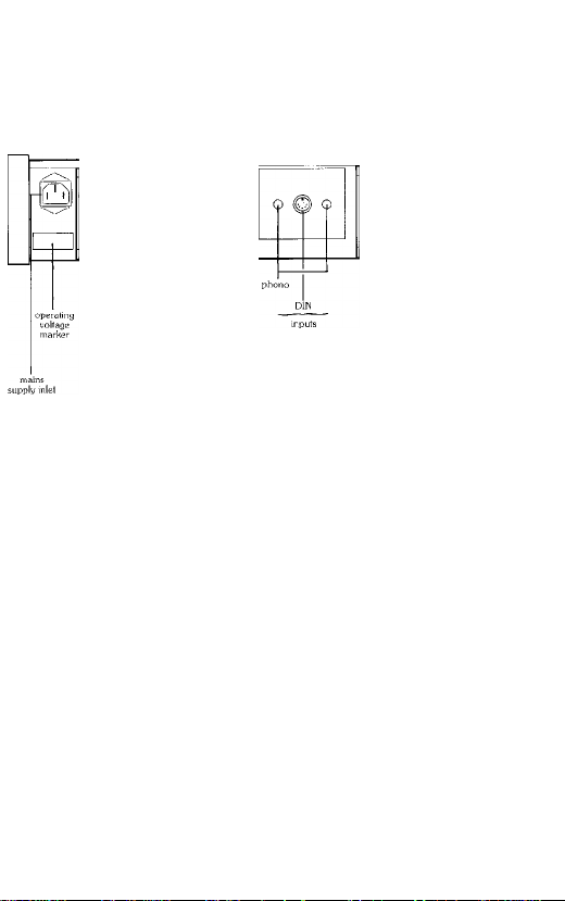
Mains Supply
The SA150 and SA200 are normally set up for use with a nominal 240V 50/60 Hz supply.
They can be modified for 220V or 120V operation by your dealer or the manufacturer. CSA
(North American} models are suitable for 120V supplies only. The correct supply voltage is
marked on the rear panel underneath the AC power supply inlet.
The AC power supply inlet of the SA150 and SA200 is via a standard lEC chassis mounting
plug. A moulded lEC socket, fitted with 2 metres (6.5 ft) of cable, is supplied to fit the lEC plug
(Note that the lEC plug and socket are a tight fit; before first using the amplifier it is therefore
important to ensure that the socket is pushed home firmly into the amplifier’s chassis plug}
The wire end of the cable should be terminated with a 3 pin (earthed) plug, wired according to
the international colour code and fitted with a 10 Amp or 13 Amp fuse. The inrernational colour
code is;
Some models may already have a suitable plug fitted as standard.
The SA150 and SA200 also have an anti-surge mains fuse fitted internally. It is recommended
that the supply to each model should be disconnected when the amplifier is not in use.
UNDER NO CIRCUMSTANCES SHOULD THE AMPLIFIER COVER BE REMOVED
Earth — green/yellow
Live — brown
Neutral — blue
UNLESS THE SUPPLY IS DISCONNECTED.
Input Connections
A combination of 5 pin DIN socket and phono connectors is fitted as standard. Certain models
may however only have either DIN or phono sockets fitted. In all cases the panel carrying these
sockets is removable to enable special versions to be supplied, e.g. for “bridged mono"
operation or professional applications. Contact your dealer or the factory for further details.
Page 5

Loudspeciker Connections
The outputs of the SA150 and SA200 are suitable for driving loudspeakers of 4 ohms nominal
impedance or higher. Both models will drive 4 ohm loads whose impedance dips to as low as
2 ohms, but care should be taken not to operate continuously at high levels into impedances of
less than 4 ohms.
The loudspeaker terminals will accept either bare wires or 4mm plugs. The left hand speaker has
its pair of terminals near the left hand of the rear panel (when viewing from the front of the
amplifier); the right hand speaker terminals are near the centre of the rear panel. The spacing of
the terminals is 19mm (0.75 inch) to accept standard twin speaker plugs.
One side of your speaker (normally the -side) should be connected to the black terminal; the
other (the +side) should be connected to the red terminal. For stereo applications it is important
to ensure that the two speakers are connected in phase (i.e. both wired the same way round to
the amplifier). Do not make any connections between the left and right loudspeaker leads
(except in “bridged mono” applications—see separate instruction sheet).
The SA150 and SA200 are unconditionally stable and suitable for use with all types of
loudspeaker leads, including the 'high definition’ types. For good practical results we recommend
the use of heavy duty cables having at least 2 sq mm cross sectional area for each conductor. It is
also good practice for the two speaker leads to be of equal length and you should ensure that all
connections at both the amplifier and speaker are tight.
It is possible to use several pairs of loudspeakers in parallel with the SA150 or SA200 provided
the overall impedance does not fall below the limits described above. No speaker switching is
provided on the amplifiers as this invariably will cause some degradation of the signal, however
slight. If it is necessary to switch speakers we recommend that the main pair be wired directly to
the amplifier wherever possible and that only the ‘extension’ speakers be switched.
With both models it is possible to reduce the value of output fuse fitted in the amplifier in order to
provide the best protection for both the speaker and amplifier. See page 7 for full details.
Heat Sink
The heat produced by the SA150 and SA200 is dissipated into the air by the large ceist heat sinks
whose fins form most of the rear panel. When the amplifier is in use these will run warm and may
become quite hot when the unit is run near full power, particularly into low impedance loads.
This is perfectly normal. However, if the fins become too hot to touch switch off the amplifier
at once and consult your dealer.
N.B. To ensure that the amplifier does not overheat it is important that the natural flow of air over
the heat sinks is not obstructed. It is also unwise to place heat sensitive items (such as L.P.
records) on top of or immediately above the amplifier.
Page 6

Front Panel Controls
Mains Power
To switch on the amplifier, depress the power on/off switch located on the extreme right of the
front panel until it latches home. The small rectangular LED (light emitting diode) adjacent to the
switch should glow green.
To turn off the power amplifier depress the power on/off switch again so that it unlatches.
The SA150 and SA200 generate very little in the way of undesirable switching surges into the
loudspeakers when they are turned on and off but they will faithfully amplify any surges generated
by preceding equipment. As the amplifiers are very powerful, these surges may cause damage to
certain loudspeakers through no fault of the power amplifier. Note that any A&R equipment likely
to be used with the SA150 or SA200 (e.g. C200 control unit or A60AP amplifier) is fully
suppressed, so that no switch on surge will occur. However, if your pre-amplifier is in any way
suspect it is wise to turn on the power amplifier some moments after switching on the
pre-amplifier, in order to allow the pre-amplifier’s circuits to settle down. Similarly, the power
amplifier should be turned off well before the preamplifier in order to allow its power supply to
discharge fully.
LED Overload Indicator
On both the SA150 and SA200 the front panel LED to the left of the power on/off switch
normally glows green to show that the DC power supplies in the amplifier are operating. It will
continue to glow green for a short time after the amplifier is switched off as the DC voltages decay.
On the SA200 only the LED also functions as an overload indicator. If either channel of the
SA2CK) clips or distorts significantly then the LED will change colour momentarily from green to
red. If the overload is maintained then the LED will glow red continuously and to avoid possible
speaker damage the preamplifier volume control should be turned down immediately.
Page 7

Fitting or Changing Side Cheeks
If your SA150 or SA200 is not already supplied fitted with Afromosia wood side cheeks it will be
fitted with thin metal transit panels. These must be removed and the appropriate wood side
cheeks fitted before the amplifier is first used. The wood cheeks are available in two
heights—standard (95mm) and tall (145mm). The latter leaves sufficient clearance underneath
the SA200 to accept the C200 control unit. To fit the cheeks, proceed as follows (see figures 3
and 4);-
1. Ensure the SA200 is disconnected from the mains supply.
2. Using a N® 2 "Posidriv’ screwdriver remove the four bright metal screws from each side of the
amplifier- This will free the transit cheeks. Do not attempt to remove the black screws as these
hold together parts of the main chassis.
3. Fit the wooden end cheeks using the M4 hex socket cap screws and washers provided. The
screws must be tightened firmly with the Allen Key provided. Ensure that the wooden cheeks
are fitted the right way round; they are counter-bored where necessary to clear protrusions on
the amplifier chassis. Note that the two side cheeks are identical.
To exchange side cheeks (e.g. from standard height to tall) simply unscrew the M4 hex socket
cap screws holding in each old cheek. The new pair may then be fitted following the procedure
of paragraph 3 above.
Never operate the amplifier without the proper side cheeks fitted as this could constitute a safety
hazard.
Page 8

Technical Details
Spares Kit
You are provided with a spares and accessory kit containing the following;-
SA150
1 lEC line socket with 2m (6.5ft) mains lead.
1 3mm AF Allen key.
2 Spare speaker fuses (2.5 Amp fast blow. 20mm x 5mm).
2 Spare speaker fuses (1.6 Amp fast blow. 20mm x 5mm).
SA200
1 lEC line socket with 2m (6.5ft) mains lead.
1 3mm AF Allen key.
2 Spare speaker fuses (3.15 Amp fast blow. 20mm x 5mm).
2 Spare speaker fuses (2 Amp fast blow, 20mm x 5mm).
In addition, if either amplifier is not already provided with factory fitted wooden side cheeks the
spares kit will also contain 8 M4 x 16mm hex socket cap screws and M4 washers, plus one pair of
side cheeks (either short or tall).
Input Connector Wiring
Viewed from rear of amplifier, or plug as wired (see Figure 5).
Figure 5
For connecting either model to the A&R C2(X) control unit (standard DIN output version) or the
A&R A60 AP amplifier, a crossover DIN to DIN lead is required. A&R leads type L—05
(0.6m, 2ft) or L—05/2 (2 metres, 6.5ft) are recommended. Either lead may also be used to
connect the SA150 and SA200 to most other manufacturers’ pre-amplifiers which use a 5 pin
180° DIN socket with the output signals on pins 1 & 4.
The phono sockets may also be used to connect the SA150 or SA2(X) to a suitable pre-amplifier.
For best results only interconnecting leads of the highest quality should be used.
The input impedance of both the SA150 and SA200 is 20 kii and the voltage gain of each
channel of both models is 29dB (28.3 times). This is equivalent to an input sensitivity of l.OOV
r.m.s. for 100 Watts r.m.s. into 8 ohms for the SA200 and 0.87V r.m.s. for 75 Watts r.m.s. into
8 ohms for the SA150. These figures ensure that both power amplifiers should work with almost
all pre-amplifiers and signal sources which provide nominal outputs of between 500mV and 2V
r.m.s. If in doubt consult your dealer.
L R
Page 9

Fuses
Output Fuses
Both the SA150 and SA200 are fitted with fuses (one per channel) in their output circuits to
provide extra protection for both amplifier and loudspeakers in the event of medium to long term
overloads. Each fuse is placed within the feedback loop of its power amplifier channel to eliminate
the audible effects of having a speaker fuse in series with the loudspeaker.
In addition, in the SA200 only, the circuit is so designed that, if an output fuse blows, not only
will the sound from the loudspeaker cease but the overload LED on the front panel will glow red
almost continuously if any attempt is made to play music through the system at normal volume
settings. This is a certain indication that one or both speaker fuses have failed and need replacing
(see over).
Choosing Output Fuse Ratings
The output fuses fitted to the SA150 and SA200 are of a sufficient value to ensure that the
amplifier will drive 4 ohm loudspeakers satisfactorily, with little risk of the fuses failing on normal
programrhe material. However many loudspeakers have a much higher average impedance than
4 ohms and in order to provide them with the optimum protection against overdriving, it may be
desirable to fit output fuses of a somewhat lower rating. Suitable spares for nominal 8 ohm
loudspeakers are provided with the SA150 and SA200, as shown in the table below. Some
suitable values for fuses (not supplied) which may be used with 16 ohm loudspeakers are also
shown. In all cases it is wise to use the lowest fuse value possible which does not fail on normal
programme material and some experimentation may be worthwhile here. Similarly, if
loudspeakers are used which will not accept the full power output of the amplifier, then the fuses
should also be down rated in order to provide the loudspeakers with best possible protection
against overload. If in doubt consult your dealer or the loudspeaker manufacturer.
Nominal impedance
of loudspeaker
4 ohms
8 ohms
16 ohms
In all cases the fuses used should be 20mm x 5mm “fast blow” types.
IN NO CIRCUMSTANCES SHOULD “SLOW BLOW" OR “ANTI SURGE” FUSES BE USED,
OR VALUES GREATER THAN THE HIGHEST LISTED IN THE TABLE ABOVE. THIS
WOULD RESULT IN INADEQUATE PROTECTION OF THE AMPLIFIER AGAINST
OVERLOAD AND WILL INVALIDATE THE GUARANTEE.
Suggested fuse value
SA150 SA200
2.5 Amp
1.6 Amp
1.0 Amp
3.15 Amp
2.0 Amp
1.25 Amp
Power Supply Fuses
These are—2.5 Amp fast blow 20mm x 5mm diameter fuses (model SA150).
These are—3,15 Amp fast blow 20mm x 5mm diameter fuses (model SA200).
THEY ARE NOT USER REPLACEABLE.
If any of these fuses fail there is probably a fault in the amplifier—do not change the fuses but
consult your dealer.
Page 10

Mains Fuses
All models are fitted with an anti surge (slow blow) 20mm x 5mm diameter fuse, designed to
protect against faults in the amplifier, transformer and mains switch. The values are shown below:
SA200 (all voltages) 5A
SA150 (220/240V) 1.6A
SA150(120V) 3.15A
THESE FUSES ARE NOT USER REPLACEABLE
Should the SA150 or SA200 fail to function at switch-on the fault is probably external to the
amplifier. In particular, check the fuse in the mains plug (and distribution board, if used) before
suspecting the power amplifier. The switch-on surge currents of the SA150 and SA200 are very
great which is why a 10 or 13 Amp fuse is recommended for the mains plug. You should also
ensure that the lEC mains socket is pushed seuaely home into the lEC plug on the back panel of
the amplifier.
Inspecting and Changing Fuses
In order to inspect or change the fuses you will need to remove the top cover (see Figures 6
and 7).
BEFORE REMOVING THE COVER ALWAYS SWITCH OFF THE AMPLIFIER AND
DISCONNECT THE MAINS SUPPLY. NOTE THAT THE MAINS FUSE REMAINS LIVE
WHENEVER THE AMPLIFIER IS PLUGGED INTO THE MAINS, EVEN WHEN THE
AMPUFIER SWITCH IS IN THE OFF POSITION.
To remove the top cover use a No 1 ‘Posidriv’ screwdriver to take out the three black screws
located along the top rear edge of the amplifier, above the heat-sinks. The cover may then be
lifted gently upwards and backwards in order to free it from its locating slot in the front panel. 1 he
positions of the fuses arc shown in Figure 4. Replacement of the cover is a straight reversal of the
above procedure.
nllMlJI nllMlII
left hand _
output fuse
max. 2 5 Amp
quick blow
(SA150)
Tiax. 3.15 Amp
quick blow
(S.A200I
Figure 6. Location of Fuses
right hand
output fuse
lax. 2.5 Amp
quick blow
¡SA150)
ax. 3.15 Amp
quick blow
)
no
ISA200)
\
NofuSER
REPLACEABl.E
Page 11

i'e®
Yso
Page 12

SA150 Technical Specification
Inputs
Fixed level inputs are connected to pin 3 (LEFT) and pin 5 (RIGHT) of a 5 pin 180° DIN socket
and/or two phono sockets located in the rear sub panel. This sub panel is removable to allow
other types of connector to be substituted, if required.
Sensitivity
Gain to loudspeaker terminals
Signal/noise ratio
Input impedance
Outputs
Loudspeaker outputs are via red and black heavy duty screw terminals. These will accept bare
wires or 4mm (‘Banana’) plugs. Suitable for 4-16 ohm loudspeakers.
The continuous power output, both channels driven (at 0.08% t.h.d., 20 Hz-20 kHz), exceeds
The typical maximum power output at 1 kHz, at clipping (0.1% t.h.d.), both channels driven is
Total Harmonic Distortion
At any level up to 75W/8 ohms, 1 kHz > 0.03% (typ. 0.01%)
At any level up to llOW/4 ohms, 1 kHz > 0.05% (typ. 0.02%)
Frequency Response
-I- 0. - 0.5 dB 10 Hz-20 kHz, It is recommended that the pre-amplifier’s high frequency response
should be curtailed to at least — 3 dB at 50 kHz.
Power Requirements
240VAC, 48-63 Hz, 500VA maximum. The unit may be dealer adjusted to work at 220V or
120V if required.
0.87V (ref. 75W/8ohms. 1 kHz)
29.0 dB at 1 kHz, non-inverting
> 100 dB, unweighted or CCIR/ARM
weighted, (ref. 75W/8 ohms)
20 kQ
75W/channel into 8 ohms
1 low/channel into 4 ohms
90W/channel into 8 ohms
125W/channel into 4 ohms
Dimensions (overall)
Weight
Width 464mm (I8V4")
Height 95mm (3^/4")
Depth 350mm (13^4”)
Net 9 kg (20 lb)
Packed 13 kg (29 lb)
Page 13

SA200 Technical Specification
Inputs
Fixed level inputs are connected to pin 3 (LEFT) and pin 5 (RIGHT) of a 5 pin 180° DIN socket
and/or two phono sockets located in the rear sub panel. This sub panel is removable to allow
other types of connector to be substituted, if required.
Sensitivity
Gain to loudspeaker terminals
Signal/noise ratio
Input impedance
Outputs
Loudspeaker outputs are via red and black heavy duty screw terminals. These will accept bare
wires or 4mm (‘Banana’) plugs. Suitable for 4-16 ohm loudspeakers.
The continuous power output, both channels driven (at 0.08% t.h.d., 20 Hz-20 kHz), exceeds
The typical maximum power output at 1 kHz. at clipping (0.1% t.h.d.), both channels driven is
Total Harmonic Distortion
At any level up to lOOW/8 ohms. 1 kHz < 0.03% (typ. 0.01%)
At any level up to 160W/4 ohms, 1 kHz < 0.05% (typ. 0.02%)
Frequency Response
-I- 0, - 0.5 dB 10 Hz-20 kHz. It is recommended that the pre-amplifier’s high frequency response
should be curtailed to at least - 3 dB at 50 kHz.
Power Requirements
240 VAC. 48-63 Hz, 600 VA maximum. The unit may be dealer adjusted to work at 220V or
120V if required.
l.OOV (ref. lOOW/8 ohms, 1 kHz)
29.0 dB at 1 kHz, non-inverting
> 100 dB. unweighted or CCIR/ARM
weighted, (ref. 100W/8ohms)
20ki>
lOOW/channel into 8 ohms
160W,/channel into 4 ohms
125W/channel into 8 ohms
195W/channcl into 4 ohms
Dimensions (overall)
Weight
Width 464mm (I8V4")
Height 95mm (3^4")
Depth 350rnm (13%")
Net 10.0 kg (22 lb)
Packed 14.0 kg (31 lb)
Page 14

Guarantee for U.K. Sales
This equipment has been fully tested and a full record of these tests made before despatch from
the factory. Both the workmanship and the performance of this equipment are (except as set out
below) guaranteed against defects for a period of one year from the date of purchase provided
that it was originally purchased from an authorised U.K. dealer under a consumer sale agreement.
(The words “consumer sale” shall be construed in accordance with Section 15 of the Supply of
Goods (Implied Terms) Act 1973).
The Manufacturers can accept no responsibility for defects arising from accident, misuse, wear and
tear, neglect or through unauthorised adjustment and or repair, neither can they accept
responsibility for damage or loss occurring during transit to or from the person claiming under this
guarantee.
This guarantee covers both labour and parts and is transferable to subsequent purchasers but the
liability of the Manufacturers is limited to the cost of repair or replacement (at the discretion of the
Manufacturers) of the defective parts and under no circumstances extends to consequential loss or
damage.
Claims under this guarantee
This equipment should be packed in the original packing and returned to the dealer from whom it
was purchased or, failing this, any other authorised A&R Cambridge dealer. If it is not possible to
return the equipment by hand, then it should be sent carriage prepaid by a reputable carrier.
Should the original packing not be available, replacement packing can be purchased from the
Manufacturers. The equipment should not be sent by post.
DO NOT CONSIGN THE EQUIPMENT TO A&R CAMBRIDGE UNLESS YOU HAVE FIRST
BEEN SPECIFICALLY REQUESTED TO DO SO BY THE MANUFACTURER’S TECHNICAL
SERVICE DEPARTMENT. DO NOT UNDER ANY CIRCUMSTANCES ATTEMPT TO
DISASSEMBLE THE EQUIPMENT BEFORE DESPATCH.
If you have any difficulty complying with these requirements, please contact the Manufacturers at
the following address:-
A&R Cambridge Limited,
Denny End Industrial Centre,
Waterbeach,
Cambridge CB5 9PB.
Tel: (0223) 861550
Telex: 817345 (ARCAM G)
In either case you should state clearly your name and address, the date and place of purchase,
together with a brief description of the fault experienced.
In the event of equipment being returned which on test is found to comply with the published
specification the Manufacturers reserve the right to charge a reasonable fee for testing the
equipment and for return carriage.
Enquiries
The Manufacturers are happy to answer any queries you may have regarding the use of this
equipment on the condition that this enquiry is by letter and a stamped addressed envelope is
provided. You should state clearly the serial number of the unit, the dealer from whom it was
purchased and the date of purchase.
THIS GUARANTEE IN NO WAY VARIES OR REMOVES A PURCHASER’S STATUTORY
RIGHTS.
Printed by Clanpress (King’s Lynn) Ltd., King’s Lynn, Norfolk,
Issue 1 March 1983
 Loading...