

Page 1

INTEGRATED AMPLIFIER
AMPLIFICATEUR INTÉGRÉ
INTEGRIERTER VERSTÄRKER
GEÏNTEGREERDE VERSTERKER
AMPLIFICADOR INTEGRADO
HANDBOOK
MANUEL
HANDBUCH
HANDLEIDING
MANUAL
РУКОВОДСТВО
MANUALE
手册
ИНТЕГРАЛЬНЫЙ УСИЛИТЕЛЬ
AMPLIFICATORE INTEGRATO
集成放大器
SA10/SA20
Page 2

Page 3

INTEGRATED AMPLIFIER
EN
HANDBOOK
SA10/SA20
Page 4

Safety Guidelines
Important Safety Instructions
1. Read these instructions.
2. Keep these instructions.
3. Heed all warnings.
4. Follow all instructions.
5. Do not use this apparatus near water.
6. Clean only with dry cloth.
7. Do not block any ventilation openings. Install in
accordance with the manufacturer’s instructions.
8. Do not install near any heat sources such as radiators,
heat registers, stoves, or other apparatus (including
amplifiers) that produce heat.
9. Do not defeat the safety purpose of the polarized or
grounding-type plug.
A polarized plug has two blades with one wider
than the other. A grounding type plug has two
blades and a third grounding prong. The wide blade
or the third prong are provided for your safety. If the
provided plug does not fit into your outlet, consult
an electrician for replacement of the obsolete outlet.
10. Protect the power cord from being walked on
or pinched particularly at plugs, convenience
receptacles, and the point where they exit from the
apparatus.
11. Only use attachments/accessories specified by the
manufacturer.
12. Use only with the cart, stand, tripod, bracket, or
table specified by the manufacturer, or sold with the
apparatus.
When a cart is used, use caution
when moving the cart/apparatus
combination to avoid injury from tipover.
13. Unplug this apparatus during lightning storms or
when unused for long periods of time.
14. Refer all servicing to qualified service personnel.
Servicing is required when the apparatus has been
damaged in any way, such as power-supply cord or
plug is damaged, liquid has been spilled or objects
have fallen into the apparatus, the apparatus has
been exposed to rain or moisture, does not operate
normally, or has been dropped.
15. Object or liquid entry
WARNING – Take care that objects do not fall and
liquids are not spilled into the enclosure through
any openings. The equipment shall not be exposed
to dripping or splashing. Liquid-filled objects such
as vases should not be placed on the equipment.
16. Climate
The equipment has been designed for use in
moderate climates and in domestic situations.
17. Cleaning
Unplug the unit from the mains supply before
cleaning.
The case should normally only require a wipe with
a soft, lint-free cloth. Do not use chemical solvents
for cleaning.
We do not advise the use of furniture cleaning
sprays or polishes as they can cause permanent
white marks.
18. Power sources
Only connect the equipment to a power supply of
the type described in the operating instructions or
as marked on the equipment.
The primary method of isolating the equipment
from the mains supply is to remove the mains plug.
The equipment must be installed in a manner that
makes disconnection possible.
19. Abnormal smell
If an abnormal smell or smoke is detected from the
equipment, turn the power off immediately and
unplug the equipment from the wall outlet. Contact
your dealer and do not reconnect the equipment.
20. Damage requiring service
The equipment should be serviced by qualified
service personnel when:
A. The power-supply cord or the plug has been
damaged, or
B. Objects have fallen, or liquid has spilled into the
equipment, or
C. The equipment has been exposed to rain, or
D. The equipment does not appear to operate
normally or exhibits a marked change in
performance, or
E. The equipment has been dropped or the
enclosure damaged.
CAUTION: To reduce the risk of electric shock, do not
remove cover (or back). No user serviceable parts inside.
Refer servicing to qualified service personnel.
WARNING: To reduce the risk of fire or electric shock, do
not expose this apparatus to rain or moisture.
The lightning flash with an arrowhead
symbol within an equilateral triangle, is
intended to alert the user to the presence of
uninsulated ‘dangerous voltage’ within the
product’s enclosure that may be of sufficient magnitude
to constitute a risk of electric shock to persons.
The exclamation point within an equilateral
triangle is intended to alert the user to the
presence of important operating and
maintenance (servicing) instructions in the
literature accompanying the product.
CAUTION: In Canada and the USA, to prevent electric
shock, match the wide blade of the plug to the wide slot
in the socket and insert the plug fully into the socket.
Class II product
This equipment is a Class II or double insulated electrical
appliance. It has been designed in such a way that it
does not require a safety connection to electrical earth
(“ground” in the U.S.)
Warning
Mains plug/appliance coupler is used to disconnect
device and it shall remain readily operable.
Safety Compliance
This equipment has been designed to meet the IEC/EN
60065 international electrical safety standard.
This device complies with Part 15 of the FCC Rules.
Operation is subject to the following two conditions:
1. This device may not cause harmful interference, and
2. This device must accept any interference received,
including interference that may cause undesired
operation.
The building installation shall be regarded as providing
protection in accordance with the rating of the wall
socket outlet.
Caution on installation
For proper heat dispersal, do not install this unit in a
confined space, such as a bookcase or similar enclosure.
More than 0.3m (12in) is recommended.
Do not place any other equipment on this unit.
z
zz
z
Wall
EN-2
Page 5

EN
Pb
FCC Information(for US
customers)
PRODUCT
This product complies with Part 15 of the FCC Rules.
Operation is subject to the following two conditions:
1. This device may not cause harmful interference, and
2. This device must accept any interference received,
including interference that may cause undesired
operation.
IMPORTANT NOTICE: DO NOT MODIFY THIS
PRODUCT
This product, when installed as indicated in the
instructions contained in this manual, meets FCC
requirements. Modification not expressly approved by
ARCAM may void your authority, granted by the FCC, to
use the product.
NOTE
This product has been tested and found to comply with
the limits for a Class B digital device, pursuant to Part 15
of the FCC Rules. These limits are designed to provide
reasonable protection against harmful interference in a
residential installation.
This product generates, uses and can radiate radio
frequency energy and, if not installed and used in
accordance with the instructions, may cause harmful
interference to radio communications. However, there
is no guarantee that interference will not occur in a
particular installation. If this product does cause harmful
interference to radio or television reception, which can
be determined by turning the product OFF and ON, the
user is encouraged to try to correct the interference by
one or more of the following measures:
Reorient or relocate the receiving antenna.
Increase the separation between the equipment and
receiver.
Connect the product into an outlet on a circuit
different from that to which the receiver is connected.
Consult the local retailer authorized to distribute
this type of product or an experienced radio/TV
technician for help
Safety Information (for European
customers)
Avoid high temperatures. Allow for sufficient heat
dispersion when installed in a rack.
Handle the power cord carefully. Hold the plug when
unplugging the cord.
Keep the unit free from moisture, water, and dust.
Unplug the power cord when not using the unit for
long periods of time.
Do not obstruct the ventilation holes.
Do not let foreign objects into the unit.
Do not let insecticides, benzene, and thinner come in
contact with the unit.
Never disassemble or modify the unit in any way.
Ventilation should not be impeded by covering the
ventilation openings with items, such as newspapers,
tablecloths or curtains.
Naked flame sources such as lighted candles should
not be placed on the unit.
Observe and follow local regulations regarding
battery disposal.
Do not expose the unit to dripping or splashing
fluids.
Do not place objects filled with liquids, such as vases,
on the unit.
Do not handle the mains cord with wet hands.
When the switch is in the OFF position, the equipment
is not completely switched off from MAINS.
The equipment shall be installed near the power
supply so that the power supply is easily accessible.
A note about recycling
This product’s packaging materials are recyclable
and can be reused. Please dispose of any materials in
accordance with the local recycling regulations.
When discarding the unit, comply with local rules or
regulations.
Batteries should never be thrown away or incinerated
but disposed of in accordance with the local
regulations concerning battery disposal.
This product and the supplied accessories, excluding
the batteries, constitute the applicable product
according to the WEEE directive
Correct disposal of this product
These markings indicate that this product should not be
disposed with other household waste throughout the
EU.
To prevent possible harm to the environment or
human health from uncontrolled waste disposal and
to conserve material resources, this product should be
recycled responsibly.
To dispose of your product, please use your local return
and collection systems or contact the retailer where the
product was purchased.
EN-3
Page 6

Welcome
Thank you and congratulations...
...for purchasing your Arcam SA10/SA20 integrated amplifier.
Arcam has been producing specialist audio products of remarkable quality for over three decades and the new
SA10/SA20 integrated amplifier is the latest in a long line of award winning Hi-Fi. The design of the HDA range
draws upon all of Arcam’s experience as one of the UK’s most respected audio companies, to produce Arcam’s best
performing range of stereo amplifiers yet – designed and built to give you years of listening enjoyment.
This handbook is a guide to installing and using the SA10/SA20 and includes information on its more advanced
features. Use the contents list on the next page to guide you to the section of interest.
We hope that your product will give you years of trouble-free operation. In the unlikely event of any fault, or if you
simply require further information about Arcam products, our network of dealers will be happy to help you. Further
information can also be found on the Arcam website at www.arcam.co.uk.
Your SA10/SA20 development team
EN-4
Page 7

Contents
EN
Safety Guidelines EN-2
Welcome EN-4
Overview EN-6
Placing The Unit EN-6
Power EN-6
Interconnect Cables EN-6
Front Panel Connections and Controls EN-7
Rear Panel Connections and Controls EN-8
Network Connection EN-9
RS232 Connection EN-9
USB Connection EN-9
Operation EN-10
Switching On EN-10
Setup Menu EN-10
Auto Standby EN-10
Display EN-10
Phono Input EN-10
Loudspeakers EN-11
Single Wiring EN-11
Bi-Amping EN-12
Remote Control EN-13
Setup Menu EN-14
Before You Begin… EN-14
System Settings EN-14
Network Settings EN-14
Troubleshooting EN-15
SA10 Specications EN-16
SA20 Specications EN-17
Worldwide Guarantee EN-18
Selecting An Audio Source EN-10
Digital Audio Inputs EN-10
Analogue Audio Inputs EN-10
Pre-Amplifier Output EN-10
Adjusting The Balance EN-10
Listening EN-10
EN-5
Page 8

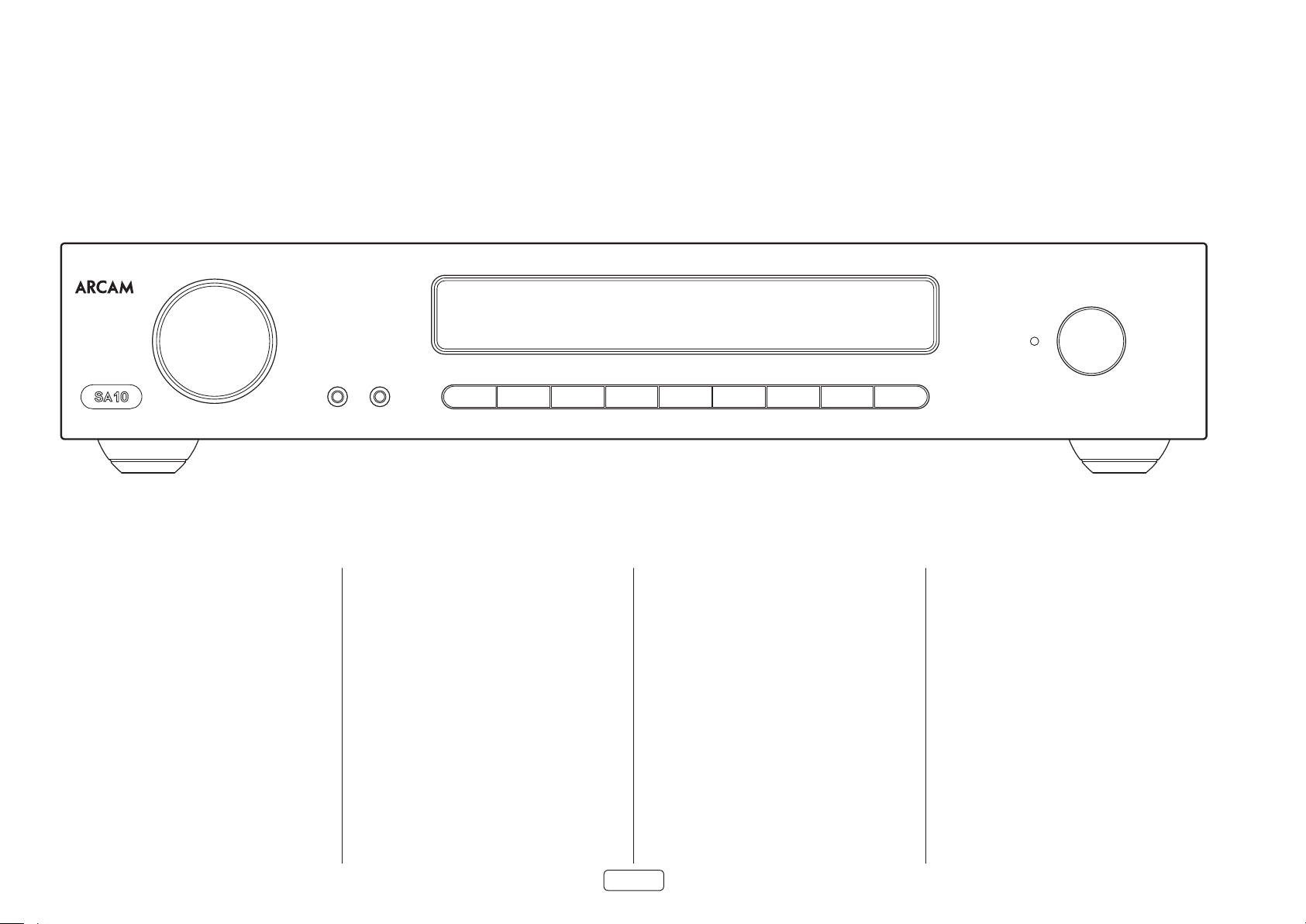
Overview
INTEGRATED AMPLIFIER
PHONES
Arcam’s SA10/SA20 amplier
Arcam’s SA10/SA20 integrated amplifier provides class
leading sound quality for the best reproduction of your
music.
Drawing on the many years of amplifier design
experience at Arcam, this product uses the best quality
components and engineering practice to produce a
product that will give many years of musical pleasure
and reliable service.
The SA10/SA20 is designed to produce a level of
performance that will truly bring your music to life.
Placing The Unit
Place the amplifier on a level, firm surface, avoiding
direct sunlight and sources of heat or damp.
Do not place the SA10/SA20 on top of a power
amplifier or other source of heat.
Do not place the amplifier in an enclosed space such
as a bookcase or closed cabinet unless there is good
provision for ventilation. The SA10/SA20 is designed
to run warm during normal operation.
Do not place any other component or item on top
of the amplifier as this may obstruct airflow around
the heat-sink, causing the amplifier to run hot. (The
unit placed on top of the amplifier would become
hot, too.)
Make sure the remote-control receiver to the right
of the front panel display is unobstructed, otherwise
this will impair the use of the remote-control.
Do not place your record deck on top of this
unit. Record decks are very sensitive to the noise
generated by mains power supplies which will be
heard as a background ‘hum’ if the record deck is too
close.
The normal function of the unit may be disturbed by
strong electromagnetic interference. If this occurs,
simply reset the unit with the power button, or move
the unit to another location.
Power
The amplifier is supplied with a moulded mains plug
already fitted to the lead. Check that the plug supplied
fits your supply – should you require a new mains lead,
please contact your Arcam dealer.
If your mains supply voltage or mains plug is different,
please contact your Arcam dealer immediately
POWERSATAVBDCDPVRSTBMUTE AUX PHONOAUX
Push the IEC plug end of the power cable into the power
socket on the back of the amplifier, making sure that it
is pushed in firmly. Plug the other end of the cable into
your mains socket and switch the socket on.
Interconnect Cables
We recommend the use of high-quality screened cables
that are designed for the particular application. Other
cables will have different impedance characteristics
that will degrade the performance of your system (for
example, do not use cabling intended for video use to
carry audio signals). All cables should be kept as short as
is practically possible.
It is good practice when connecting your equipment to
make sure that the mains power-supply cabling is kept
as far away as possible from your audio cables. Failure to
do so may result in unwanted noise in the audio signals.
EN-6
Page 9

Front Panel Connections and Controls
EN
VOLUME CONTROL
See “Volume Control” on page EN-10
Analogue 3.5mm stereo socket, intended
AUX INPUT
for connecting an external analogue
source
See “Analogue Audio Inputs” on page EN-10
PHONES
POWER INDICATOR AND POWER
SWITCH
See “Switching On” on page EN-10
INTEGRATED AMPLIFIER
POWERSATAVBDCDPVRSTBMUTE AUX PHONOAUX
Mute/unmute the SA10/SA20 audio output
See “Muting Output” on page EN-10
NOTE: This button is also used for entering the setup menu.
See “Entering Setup Mode” on page EN-14.
PHONES
3.5mm stereo socket, intended for use with headphones
See “Listening Using Headphones” on page EN-10
MUTE
INPUT SELECT
See “Selecting An Audio Source” on page EN-10
EN-7
Page 10

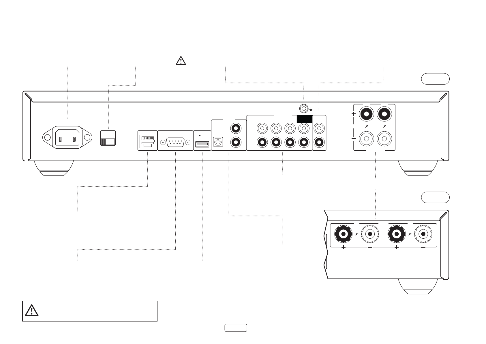
Rear Panel Connections and Controls
POWER INLET
Connect the correct
mains cable here
POWER INLET
110-120V/220-240V ~ 50/60Hz
VOLTAGE SELECT
Ensure that the voltage selected
matches the local power supply
SUPPLY
VOLTAGE
SWITCH POSITIONS
115 = 110 - 120V ~
230 = 220 - 240V ~
PHONO GROUND CONNECTION
Connect the turntable earth lead, if required
Note that this terminal must not be
used as a safety earth
DIGITAL IN
SAT
RS232NET USB
5V 100mA
BD
AV
ANALOGUE IN
CD PVR STB
L
R
PHONO
(MM)
PRE
OUT
ANALOGUE AUDIO INPUTS
Phono (MM) and line level audio inputs
See “Phono Input” on page EN-10 and “Analogue
Audio Inputs” on page EN-10
PRE-AMPLIFIER OUTPUT
Provides the pre-amplifier output for use
in a bi-amplified system.
See “Pre-Amplifier Output” on page EN-10
R
4-16 OHMS
CLASS 2 WIRING
L
SPEAKER TERMINALS
See “Loudspeakers” on page EN-11
SA10
SA20
Connect this socket to a port on your network
NETWORK
router using an Ethernet patch cable
See “Network Connection” on page EN-9
RS232
This connection allows for remote control
from a third-party home automation system or
computer
See “RS232 Connection” on page EN-9
Please read the sections “Placing The Unit”, “Power” and
“Interconnect Cables” on page EN-6 before connecting
your SA10/SA20 amplier!
This USB socket is used for software
USB
upgrades only
See “USB Connection” on page EN-9
DIGITAL AUDIO INPUTS
Optical and coaxial digital audio
connectors
See “Digital Audio Inputs” on page EN-10
EN-8
R
CLASS 2
WIRING
4-16 OHMS
L
Page 11

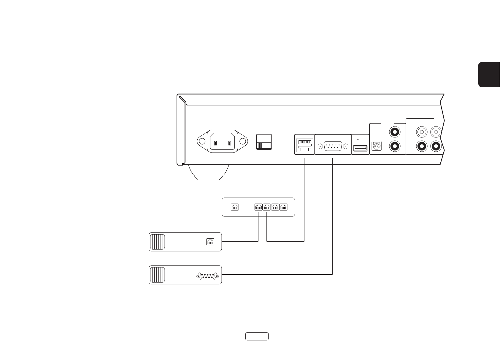
Network Connection
STB
PRE
OUT
4-16 OHMS
R L
CLASS 2 WIRING
ANALOGUE IN
PHONO
(MM)
The SA10/SA20 can be connected to a local network,
so that it can be controlled and monitored remotely.
Please refer to the control document which can be
found at www.arcam.co.uk for further information.
RS232 Connection
The RS232 input is for optional connection to a home
automation system or personal computer. Various thirdparty systems are available providing sophisticated
control over all your entertainment devices. Contact
your dealer or installer for details. The technical details of
the remote control protocol are available upon request,
by contacting Arcam at support@arcam.co.uk.
USB Connection
The USB port is used for software updates only. For the
latest software as well as further information, please visit
www.arcam.co.uk.
POWER INLET
110-120V/220-240V ~ 50/60Hz
Network Router
SUPPLY
VOLTAGE
SWITCH POSITIONS
115 = 110 - 120V ~
230 = 220 - 240V ~
1 2 3 4NET
RS232NET USB
5V 100mA
SAT
DIGITAL IN
BD
AV
EN
CD PVR
L
R
Home Automation Controller
Home Automation Controller
RS232
NET
EN-9
Page 12
Operation
Switching On
The POWER button switches the unit on and off. The
status indicator LED indicates the state of the amplifier:
it changes from red to orange then white if mains
power is connected and the unit is switched on.
Setup Menu
The SA10/SA20 setup menu allows the customization of
certain features of the amplifier. For details, please see
”Setup Menu” on page EN-14.
Auto Standby
In order to comply with international regulations for
consumer products, this unit is designed to enter a low
power standby mode if no user interaction and no
audio input signal are detected for an extended period
of time. The unit can be brought out of standby by
either turning the volume knob on the front panel in
either direction or by pressing the key on the
remote control.
The available values are from ‘OFF’ to 4 hours, in half
hour steps.
Note: if the standby time-out is set to OFF, the standby
feature will be disabled.
Display
Press the DISP button on the remote control to adjust
the brightness level of the front panel display. The
brightness level can be set to ‘FULL’, ‘DIM’ or ‘OFF’.
If the SA10/SA20 is powered off with the display
brightness set to ‘OFF’, the display will momentarily
resume to full brightness then turn off when the unit is
powered back on.
Phono Input
The SA10/SA20 provides a pre-amplification stage
to treat the low-voltage output from an MM (moving
magnet) cartridge. The PHONO input specifications are
given in “SA10 Specifications” on page EN-16 and “SA20
Specifications” on page EN-17.
WARNING: NEVER play a standard line-level source
into this input. This would result in serious damage
to both your amplier and speakers due to the extra
gain that is applied and would not be covered under
warranty.
Selecting An Audio Source
Audio sources can be selected either from the front
panel or remote control, by pressing the required
button, labelled as AUX, PHONO, STB, PVR, CD, BD,
AV, S AT.
In each case, the source is selected from the input
sockets with the corresponding name.
Note: The STB, PVR, CD, BD and AV buttons are also
used for navigating through the SA10/SA20 set up
menu, as described in “Navigating The Setup Menu” on
page EN-14.
Digital Audio Inputs
The SA10/SA20 features two coaxial and one optical
digital input, which can be connected to the respective
digital audio output of your available source equipment.
Although the inputs are labelled for specific devices,
they can be used to connect any devices with a coaxial
or optical digital output.
BD Intended for the coaxial digital output of a
Blu-ray or DVD-player
AV Intended for the coaxial digital output of
general audiovisual equipment, such as a
VCR, TV or satellite receiver
SAT Intended for the optical digital outputs
from a satellite TV receiver or cable TV box
NOTE: The SA10/SA20 supports only two channel PCM
audio input
Analogue Audio Inputs
Although the inputs are labelled for specific devices,
all have the same characteristics and each may be
used with any line-level product. The exception is the
PHONO (MM) input. Please refer to “SA10 Specifications”
on page EN-16 and “SA20 Specifications” on page EN-17).
AUX This is a 3.5mm analogue input on the front
STB Intended for the analogue outputs of a set-
PVR Intended for the analogue outputs of a
CD Intended for the analogue outputs from a
panel intended for use with devices such
as MP3 players. To connect an MP3 player
(or other portable audio device you will
need a 3.5mm to 3.5mm cable connected
(not supplied) between the AUX input
and the headphone output socket of the
portable audio player
top box
Personal Video Recorder, or similar device
CD player
Pre-Amplier Output
To use the SA10/SA20 as dedicated pre-amplifier, or
as part of a bi-amped system, connect the PRE OUT
sockets to the input sockets of your amplifier. For
connection details, see “Rear Panel Connections and
Controls” on page EN-8 and for output specification
see “SA10 Specifications” on page EN-16 and “SA20
Specifications” on page EN-17.
Adjusting The Balance
The balance setting allows you to increase the volume of
one channel (left or right) relative to the other. Altering
the balance may help restoring the stereo image for an
off-centre listening position.
To adjust the balance, press the
the remote control to change the left and right channel
balance, respectively.
BAL
or
BAL
on
Listening
Volume Control
Use the volume control knob (or the buttons on
the remote control) to change the volume. Turn the
knob clockwise to increase the volume and counterclockwise to reduce it.
Listening Using Headphones
The headphone socket (PHONES) accepts phones with
an impedance rating between 16Ω and 2kΩ, fitted with
a 3.5mm stereo jack.
The pre-amp outputs and speakers are muted when the
headphones are plugged in and the front panel displays
shows ‘Headphone’.
The headphone output is always active, unless the
amplifier has been muted.
Muting Output
The output of the SA10/SA20 can be silenced by
pressing the MUTE button on either the front panel
or the remote control. If the unit is muted, front panel
power indicator will change to orange and the display
will show “Mute”, instead of the volume level.
To cancel the mute, press MUTE for a second time or
adjust the volume (either by turning the volume control
knob or by pressing the volume control keys on the
remote control).
Processor Mode
Processor mode can be assigned to any input. In this
mode, the SA10/SA20 is set to a fixed level. Please refer
to “Processor Mode (PM) Input” on page EN-14 for details
on how to specify which input is to be used in processor
mode. For setting the desired fixed volume level, please
refer to “Processor Mode (PM) Volume” on page EN-14.
EN-10
Page 13
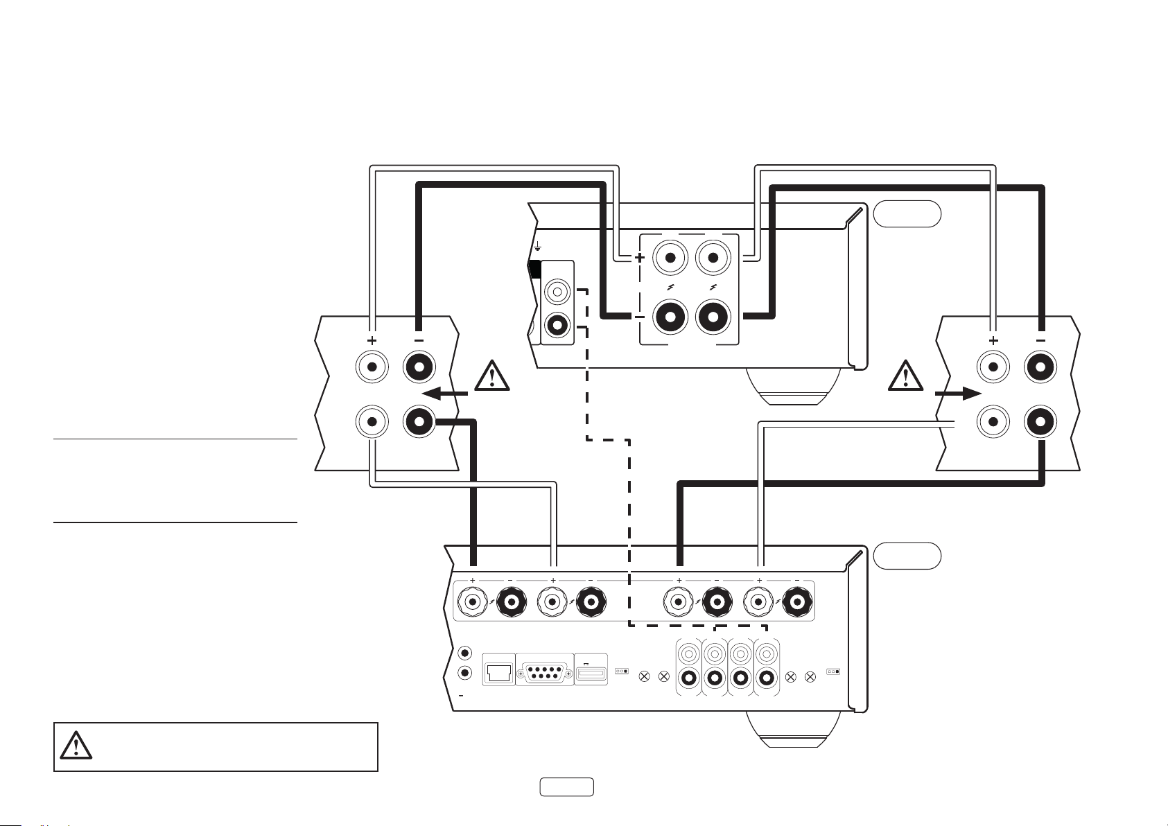
Loudspeakers
EN
Connecting Loudspeakers
There are many different ways of connecting
loudspeakers to your SA10/SA20 amplifier. The following
section describes how to connect the speakers and
amplifier for the most common configurations.
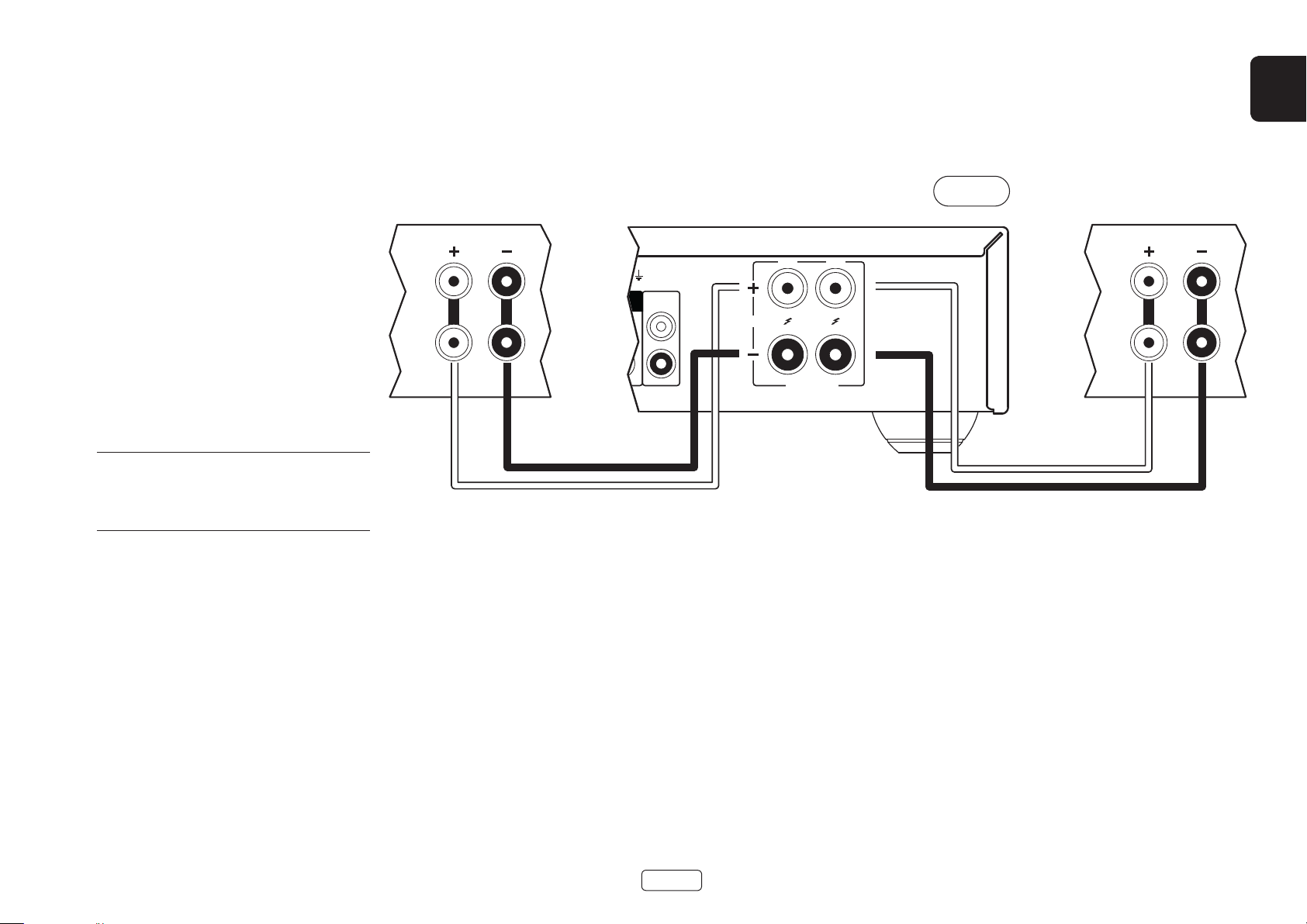
Single Wiring
If each speaker has more than one pair of connecting
terminals, use the terminals labelled ‘LF’ or ‘Low
Frequency’ on your speakers.
Connect the red positive terminal of the right speaker
connection on the amplifier (labelled R+) to the positive
terminal of your right speaker. Similarly, connect the
black negative terminal of the right speaker connection
on the amplifier (labelled R-) to the negative terminal
of your speaker. Repeat the process for the left speaker,
using the terminals labelled L+ and L- on the amplifier.
WARNING: If your speakers support bi-wiring, there
will be a strip of conductive metal connecting the lowfrequency (LF) terminals to the high-frequency (HF)
terminals; this MUST NOT BE REMOVED in a singlewired system.
R L
R
HF
PRE
OUT
LF
4-16 OHMS
L
CLASS 2 WIRING
SA10
HF
LF
Notes On Making Speaker Connections
Do not make any connections to any amplifier while it is switched on. We recommend that your amplifier is
completely disconnected from the mains supply before starting.
Before switching your amplifier on for the first time after connecting to speakers, please check all connections
thoroughly. Ensure that bare wires or cables are not touching each other or the amplifier’s chassis (which could
cause short circuits), and that you have connected positive (+) to positive and negative (–) to negative. Be sure to
check the wiring for both the amplifier and the speaker.
After making connections: switch the amplifier on, select a source signal, then gradually increase the volume to
the required listening level.
If you are unsure as to how your system should be connected, please contact your Arcam dealer who will be
happy to help you.
EN-11
Page 14
Bi-Amping
Bi-amping is the separation of the amplification of low
and high-frequency signals over two amplifiers.
Bi-amping requires the use of two amplifiers per
channel. Normally, your SA10/SA20 is used to drive
the high frequency (treble) speakers, while a second
amplifier (such as the Arcam P429) is used for the lower
(bass) frequencies.
Connect the SA10/SA20 to the speakers as described
for single wiring, with the exception that the SA10/SA20
should be connected to the speaker terminals labelled
‘HF’ or ‘High Frequency’. Next, connect the P429 power
amplifier to the ‘LF’ or ‘Low Frequency’ terminals, as
shown in the diagram. A pair of audio interconnect
cables are also required to connect the pre-amp
outputs of the SA10/SA20 to the power amplifier inputs
of the second amplifier.
WARNING: The strip of metal on the speakers
connecting the low frequency (LF) terminals to the
high frequency (HF) terminals MUST BE REMOVED.
Failure to do so will result in damage to both
ampliers, which will not normally be covered under
warranty.
SA10
R
PRE
OUT
R L
4-16 OHMS
HF
Remove
metal strips
LF
L
CLASS 2 WIRING
HF
Remove
metal strips
LF
P429
In this example, the P429 is congured in bridge mode.
Refer to the P429 user manual for various conguration
modes.
TRIGGER
IN
TRIGGER
OUT
12V 100mA
CH4
NET RS232
CH3
EN-12
USB
5V 100mA
3/4 MODE
ST/DM/BR
TRIM
4 3
OUT4
CH2
IN4
OUT3
CH1
IN2
OUT2
OUT1
IN1
1/2 MODE
TRIM
ST/DM/BR
2 1
IN3
Page 15
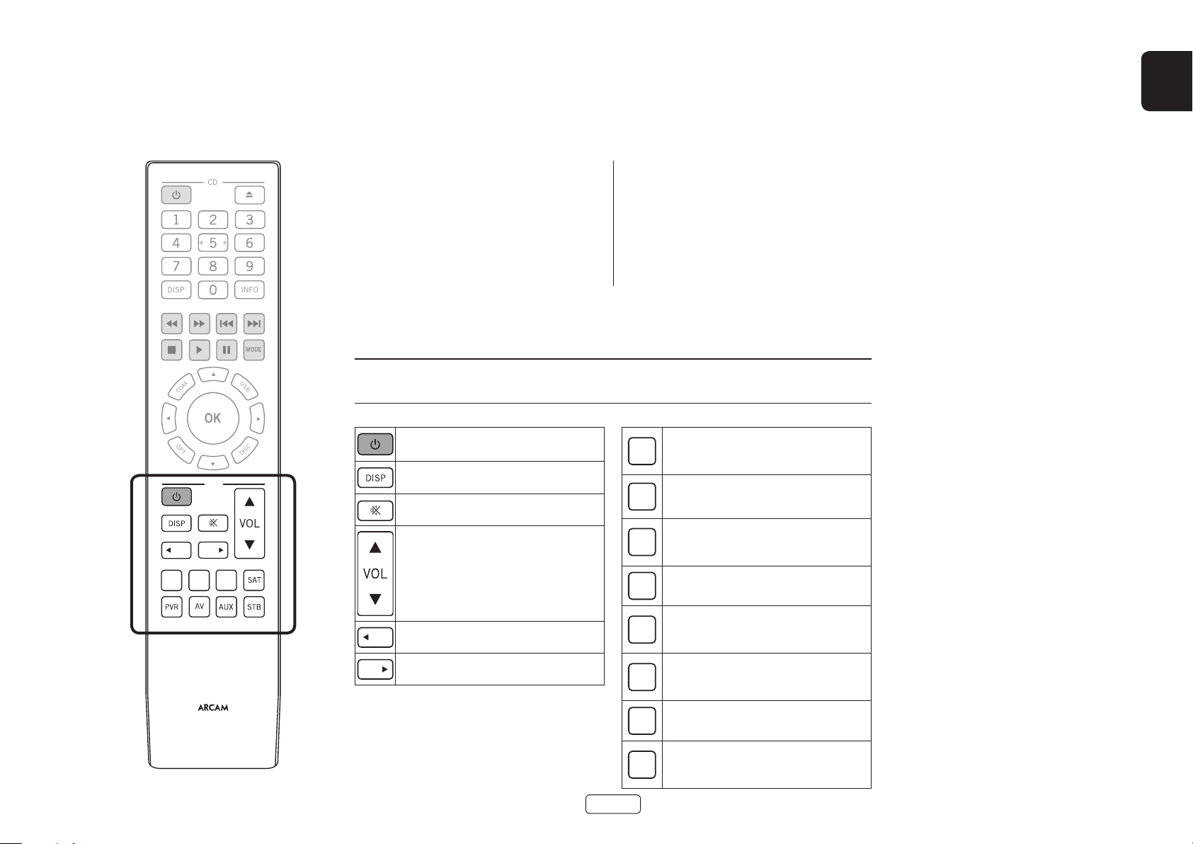
Remote Control
MODE
COAX
OK
OPT
USB
DISP
DISC
CD
INFO
EN
AMP
BAL BAL
The remote control is pre-programmed for use with the
SA10/SA20 amplifier and also an Arcam CD player. The
information in this section applies to the AMP section
of the remote control only.
Make sure the two AAA batteries (supplied) are installed
before attempting to use the remote control.
1. With the remote face down, press down on the nonslip indentations of the battery compartment cover
2. Insert the two AAA batteries (supplied). Take care to
insert the batteries in the right direction by following
the ‘+’ and ‘-’ marks in the battery compartment
3. Slide the battery compartment cover back and lock
it in place with a click
The remote control requires a clear line of sight to
the front panel of the SA10/SA20 to ensure reliable
operation.
and slide the cover off
NOTE: The supplied remote control is designed to support both the SA10/SA20 integrated amplier as well as an
Arcam CD player. The section below applies to the AMP section of the remote control only. Refer to the CD user
manual for description on the CD section of the remote control unit.
Toggles power between standby and
powered on
Select the PHONO (MM) input
PHONO
Cycles through the front panel display
brightness options
Toggles the mute function of the amplifier
Increase/decrease amplifier volume
Select the CD analogue input
CD
Select the BD coaxial digital input
BD
PHONO
CD BD
Adjust the balance of the left channel
BAL
Adjust the balance of the right channel
BAL
EN-13
Select the SAT optical digital input
SAT
Select the PVR analogue input
PVR
Select the AV coaxial digital input
AV
Select the 3.5mm socket analogue input
AUX
(located on the front panel)
Select the STB analogue input
STB
Page 16

Setup Menu
Before You Begin…
The setup menu allows you to configure various aspects
of the SA10/SA20 integrated amplifier.
Entering Setup Mode
To enter the setup menu, press and hold the MUTE key
on the front panel for approximately 3 seconds.
Navigating The Setup Menu
The setup menu can be navigated by pressing the front
panel keys that correspond to the function shown on
the display, as shown below.
To change a setting, simply turn the control knob left
or right.
AVBDCDPVRSTB
HOME Exit the menu and return to the
home display
UP Navigate to the previous menu
option
DOWN Navigate to the next menu option
LEFT Navigate left or move to the
previous field
RIGHT Navigate right or move to the next
field
OK Save the current setting and move
to next option
System Settings
Display
Allows the brightness of the front panel display to be
changed. The available settings are Full, Dim and O.
The default setting is Dim.
Balance
Turn the SA10/SA20 volume control knob left and
right to change the left and right channel balance,
respectively. The default setting is 0.
Phones Override
Control whether or not the speaker outputs are muted
when a pair of headphones are connected to the
PHONES socket on the front panel. The default is O.
Timeout
This option allows you to choose the length of idle time
before the unit goes into standby. The available options
are O, 30 minutes, 1, 2 and 4 hours. The default setting
is 30 minutes.
Processor Mode (PM) Input
Specify which input is to be used in processor mode.
This mode can be assigned to any input. In this case, the
SA10/SA20 output level is set to a fixed level. The default
setting is None.
Processor Mode (PM) Volume
Specify the required volume level for the processor
mode input. The default is volume is 30.
IR System Code
Change the IR system code that the SA10/SA20
responds to (either 16 or 19). The default code is 16.
Note: The supplied remote control supports IR system
code 16 only and cannot be changed.
Version
Displays the software version of the unit.
System Update
This option allows you to perform a software update of
the system.
System Reset
Restores the SA10/SA20 to its factory default settings.
Network Settings
Net Standby
Enables or disables the network control of the
SA10/SA20 while the unit is in standby. The default
setting is O.
Note: The unit can still be controlled via RS232
commands, even when network standby is disabled.
RS232 Standby
Enables or disables the RS232 control of the SA10/SA20
while the unit is in standby. The default setting is O.
Network Setup
You can set your SA10/SA20 to obtain an IP address
automatically when it connects to your network. To do
so, select DHCP On and press OK.
Some providers require that you enter a fixed IP address.
To do this, select DHCP O and press OK. Use the left
and right navigation keys to move between fields and
turn the SA10/SA20 volume control knob to set the
values. Press OK to save the settings.
The default network setup mode is DHCP On.
Network Name
This option allows you to rename the amplifier. Use
the left and right navigation keys to move between
segments and turn the SA10/SA20 volume control knob
to change each value. The default value is SA10-XXXX or
SA20-XXXX, where XXXX are the last four characters of
the product’s MAC address.
Network Info
Displays all the information related to the network setup,
as follows: DHCP setting, IP address, MAC address and
Network Name of the unit.
BACK Save the current setting and exit
menu option
EN-14
Page 17
Troubleshooting
Problem Check the following
No sound The SA10/SA20 amplifier is correctly plugged in and switched on
Your audio source is correctly connected, the correct input is selected
and it is not muted
The SA10/SA20 is not in protection mode, as described below
Sound cuts-out unexpectedly The SA10/SA20 may enter a protection mode, depending on the fault
The unit responds erratically or not at
all to the remote control
The front panel display is blank The display hasn’t been turned off. Press the DISP button on the
Hum on the analogue input All cables are making a good connection. If necessary withdraw the
Can not connect to a wired network The Ethernet cable you are using is correctly connected between the
being detected. The front panel LED will indicate the fault type, according
to the list below
FLASHING BLUE: The internal temperature of the unit reached an
unsafe level. Allow the SA10/SA20 to cool off
FLASHING RED: The SA10/SA20 amplifier detected a speaker short
circuit. Should this happen, please inspect all the speaker cables to
make sure none of them are shorted together. This fault is very common
when bare wires are being used to make speaker connections
FLASHING ORANGE: The amplifier detected a DC offset.
Following any of the faults described above, the amplifier will turn itself
off and power to the speakers will be removed. To continue using the
SA10/SA20, the fault must be removed and the unit must be turned OFF
then back ON
There are fresh batteries in the remote control
The front panel window is visible and you are pointing the remote
control towards it
remote control. See “Display” on page EN-10
cable from the connector and plug it fully in again (turn the power off
before doing this)
The connections inside the source cable connector are not broken or
badly soldered
If the hum originates only when one particular source component is
connected, that an aerial cable, or dish connection to this source is
ground isolated. Contact your installation contractor
SA10/SA20 and the network hardware
The network is set up for fixed IP addressing and you have the
SA10/SA20 set to use DHCP On.
The network is set up for DHCP and you have the SA10/SA20 set to
use fixed IP addressing. See “Network Connection” on page EN-9 and
“Network Settings” on page EN-14
EN
EN-15
Page 18
SA10 Specications
Continuous power output (20Hz—20kHz at 0.5% THD), per channel
Both channels, 8Ω, 20Hz—20kHz 50W
Single channel, 4Ω, at 1kHz 90W
Harmonic distortion, 80% power, 8Ω at 1kHz 0.003%
Analogue Inputs
Phono (MM) cartridge:
Input sensitivity at 1kHz 5mV
Input impedance 47kΩ + 100pF
Frequency response (ref. RIAA curve) 20Hz – 20kHz ± 1dB
Signal/Noise ratio (A-wtd) 50W, ref. 5mV input 80dB
Overload margin, ref. 5mV at 1kHz 21dB
Line Inputs:
Nominal sensitivity 1V
Input impedance 10kΩ
Maximum input 6Vrms
Frequency response 20Hz – 20kHz ± 0.2dB
Signal/Noise ratio (A-wtd) 50W, ref. 1V input 106dB
Digital Inputs
DAC ESS9016K2M
Frequency response 20Hz - 20kHz ± 0.05dB
Total harmonics distortion + Noise 0.0007%
Signal/Noise ratio (A-wtd) 115dB
Supported sample rates Optical 32kHz, 44.1kHz, 48kHz, 88.2kHz, 96kHz
Coaxial 32kHz, 44.1kHz, 48kHz, 88.2kHz, 96kHz, 176.4kHz, 192kHz
Bit depth 16-bit – 24-bit
Pre-amplier output
Nominal output level 630mV
Output impedance 230Ω
Headphone output
Maximum output level into 600Ω 5Vrms
Output impedance 1Ω
Load range 16Ω – 2kΩ
General
Mains voltage 110–120V or 220–240V, 50–60Hz
Maximum power consumption 350W
Dimensions W x H x D (including feet, control
knob and speaker terminals)
Weight (net) 8.4kg
Weight (gross) 10.7kg
Supplied accessories Mains leads
433x87x310mm
Remote control
2 x AAA batteries
EN-16
Page 19
SA20 Specications
EN
Continuous power output (20Hz—20kHz at 0.5% THD), per channel
Both channels, 8Ω, 20Hz—20kHz 90W
Single channel, 4Ω, at 1kHz 180W
Harmonic distortion, 80% power, 8Ω at 1kHz 0.002%
Analogue Inputs
Phono (MM) cartridge:
Input sensitivity at 1kHz 5mV
Input impedance 47kΩ + 100pF
Frequency response (ref. RIAA curve) 20Hz – 20kHz ± 1dB
Signal/Noise ratio (A-wtd) 50W, ref. 5mV input 80dB
Overload margin, ref. 5mV at 1kHz 21dB
Line Inputs:
Nominal sensitivity 1V
Input impedance 10kΩ
Maximum input 6Vrms
Frequency response 20Hz – 20kHz ± 0.2dB
Signal/Noise ratio (A-wtd) 50W, ref. 1V input 106dB
Digital Inputs
DAC ESS9038K2M
Frequency response 20Hz - 20kHz ± 0.05dB
Total harmonics distortion + Noise 0.0007%
Signal/Noise ratio (A-wtd) 115dB
Supported sample rates Optical 32kHz, 44.1kHz, 48kHz, 88.2kHz, 96kHz
Coaxial 32kHz, 44.1kHz, 48kHz, 88.2kHz, 96kHz, 176.4kHz, 192kHz
Bit depth 16-bit – 24-bit
Pre-amplier output
Nominal output level 630mV
Output impedance 230Ω
Headphone output
Maximum output level into 600Ω 5Vrms
Output impedance 1Ω
Load range 16Ω – 2kΩ
General
Mains voltage 110–120V or 220–240V, 50–60Hz
Maximum power consumption 500W
Dimensions W x H x D (including feet, control
knob and speaker terminals)
Weight (net) 9.2kg
Weight (gross) 11.1kg
Supplied accessories Mains leads
433x87x323mm
Remote control
2 x AAA batteries
EN-17
All specication values are typical unless otherwise
stated. Arcam has a policy of continuous improvement
for its products. This means that designs and
specications are subject to change without notice.
E&OE.
Page 20

Worldwide Guarantee
This entitles you to have the unit repaired free of charge, during the first two years after purchase, provided that
it was originally purchased from an authorised Arcam dealer. The Arcam dealer is responsible for all after-sales
service. The manufacturer can take no responsibility for defects arising from accident, misuse, abuse, wear and tear,
neglect or through unauthorised adjustment and/or repair, neither can they accept responsibility for damage or loss
occurring during transit to or from the person claiming under the guarantee.
The warranty covers:
Parts and labour costs for three years from the purchase date. After three years you must pay for both parts and
labour costs. The warranty does not cover transportation costs at any time.
Claims under guarantee
This equipment should be packed in the original packing and returned to the dealer from whom it was purchased.
It should be sent carriage prepaid by a reputable carrier – not by post. No responsibility can be accepted for the
unit whilst in transit to the dealer or distributor and customers are therefore advised to insure the unit against loss
or damage whilst in transit.
For further details contact Arcam at support@arcam.co.uk.
Problems?
If your Arcam dealer is unable to answer any query regarding this or any other Arcam product please contact Arcam
Customer Support at the above address and we will do our best to help you.
On-line registration
You can register your product on-line at www.arcam.co.uk.
EN-18
Page 21

AMPLIFICATEUR INTÉGRÉ
MANUEL
FR
SA10/SA20
Page 22

Bienvenue
Merci et félicitations...
...pour l’achat de votre amplificateur SA10/SA20 intégré Arcam.
Arcam fabrique des produits audio spécialisés d’une qualité remarquable depuis plus de trois décennies et le nouvel
amplificateur intégré SA10/SA20 est le dernier modèle d’une longue lignée de produits hi-fi prisés. Le design de
la gamme HDA puise dans l’expérience d’Arcam en tant qu’une des sociétés d’audio les plus respectées, afin de
produire la gamme la plus performante d’amplificateurs stéréo conçue à ce jour et construite pour vous donner des
années de plaisir d’écoute.
Ce manuel est un guide d’installation et d’utilisation du SA10/SA20 contenant des informations sur ses
fonctionnalités plus avancées. Reportez-vous à la table des matières page suivante pour rechercher les rubriques
qui vous intéressent plus particulièrement.
Nous espérons que votre appareil vous assurera des années de fonctionnement sans le moindre problème.
Dans l’éventualité, peu probable, où une panne surviendrait, ou si vous recherchez simplement des informations
supplémentaires sur les produits Arcam, les représentants de notre réseau de revendeurs se feront un plaisir de vous
aider. D’autres informations sont disponibles sur notre site web d’Arcam à l’adresse www.arcam.co.uk.
Votre équipe de développement du SA10/SA20
FR-2
Page 23

Table des matières
Bienvenue FR-2
Haut-parleurs FR-9
FR
Aperçu FR-4
Mise en place de l’appareil FR-4
Alimentation FR-4
Câbles de branchement FR-4
Connexions et commandes de la façade FR-5
Connexions et commandes au dos de l’appareil FR-6
Connexion réseau FR-7
Connexion RS232 FR-7
Connexion USB FR-7
Guide d’utilisation FR-8
Mise en marche FR-8
Menu de configuration FR-8
Veille automatique FR-8
Écran FR-8
Entrée phono FR-8
Sélection d’une source audio FR-8
Entrées audio numériques FR-8
Câblage simple FR-9
Amplification double FR-10
Télécommande FR-11
Menu de conguration FR-12
Avant de commencer… FR-12
Réglages du système FR-12
Paramètres réseau FR-12
Dépannage FR-13
SA10 Spécications FR-14
SA20 Spécications FR-15
Garantie internationale FR-16
Entrées audio analogiques FR-8
SORTIE DE PRÉAMPLIFICATEUR FR-8
Réglage de la balance FR-8
Écoute FR-8
FR-3
Page 24
Aperçu
INTEGRATED AMPLIFIER
PHONES
Amplicateur SA10/SA20
d’Arcam
L’amplificateur intégré SA10/SA20 d’Arcam fournit une
qualité du son de premier ordre offrant la meilleure
reproduction de votre musique.
S’appuyant sur de nombreuses années d’expérience
dans le domaine de la conception des amplificateurs
chez Arcam, ce produit utilise des composants et des
principes techniques de grande qualité pour proposer
un produit qui vous garantira de nombreuses années
de plaisir musical et un service fiable.
Le SA10/SA20 est conçu pour produire un niveau de
performance permettant véritablement de donner vie
à votre musique.
Mise en place de l’appareil
Mettez l’amplificateur sur une surface ferme, de
niveau, évitant la lumière directe du soleil et des
sources de chaleur et d’humidité.
Ne posez pas le SA10/SA20 au-dessus d’un amplificateur
de puissance ou de toute autre source de chaleur.
Ne mettez pas l’amplificateur dans un espace fermé
tel qu’une bibliothèque ou une armoire à moins
qu’elle ne soit pourvue d’une bonne ventilation. Le
SA10/SA20 est conçu pour chauffer pendant son
fonctionnement normal.
Ne mettez aucun composant ou élément au-dessus
de l’amplificateur, car il peut obstruer le flux d’air autour
du dissipateur thermique, provoquant l’échauffement
de l’amplificateur. (L’unité placée au-dessus de
l’amplificateur deviendrait elle aussi bouillante.)
Assurez-vous que le récepteur de la télécommande
sur la droite du panneau d’affichage n’est pas
obstrué, sinon cela peut générer l’utilisation de la
télécommande.
Ne posez pas votre platine-disque sur cet appareil.
Les platines sont des appareils très sensibles aux
bruits générés par l’alimentation secteur. Ces derniers
peuvent s’entendre en bruit de fond si la platine est
trop proche de l’appareil.
Le fonctionnement normal de l’appareil peut être
gêné par de fortes perturbations électromagnétiques.
Si cela se produit, il suffit de réinitialiser l’appareil avec
le bouton d’alimentation, ou de déplacer l’appareil
dans un autre lieu.
Alimentation
L’amplificateur est livré avec une prise de courant
moulée intégrée au câble. Vérifiez que la prise livrée
correspond bien à votre circuit électrique. S’il vous faut
un autre câble d’alimentation, veuillez vous adresser à
votre revendeur Arcam.
Si la tension ou les prises de votre circuit électrique sont
différentes, contactez immédiatement votre revendeur
Arcam
FR-4
POWERSATAVBDCDPVRSTBMUTE AUX PHONOAUX
Insérez la prise IEC du câble d’alimentation dans la prise
à l’arrière de l’amplificateur, en veillant à la pousser
fermement. Branchez l’autre extrémité du câble sur
votre prise secteur, et allumez celle-ci.
Câbles de branchement
Il est recommandé d’utiliser des câbles blindés de haute
qualité, conçus pour ce genre d’application. L’utilisation
d’autres câbles, dont les caractéristiques d’impédance
diffèrent, risque d’affecter les performances de votre
système. (Par exemple, n’utilisez pas de câble conçu
pour un usage vidéo pour le transport des signaux
audio). Les câbles doivent être aussi courts que possible.
Lors de la connexion du matériel, il convient de vérifier
que les câbles d’alimentation secteur sont positionnés
le plus loin possible de vos câbles audio. Vous éviterez
ainsi les bruits indésirables dans les signaux audio.
Page 25

Connexions et commandes de la façade
CONTRÔLE DU VOLUME
voir «Contrôle du volume» à la
page FR-8
Prise stéréo analogique de 3,5 mm,
ENTRÉE AUX
destinée au branchement d’une source
analogique externe
voir «Entrées audio analogiques» à la
page FR-8
PHONES
TÉMOIN D’ALIMENTATION
ET INTERRUPTEUR
D’ALIMENTATION
voir «Mise en marche» à la
page FR-8
INTEGRATED AMPLIFIER
POWERSATAVBDCDPVRSTBMUTE AUX PHONOAUX
FR
Active/désactive la sortie audio du SA10/SA20
voir «Mise en sourdine de la sortie» à la page FR-8
REMARQUE : Cette touche est également utilisée pour
Voir «Accès au mode de configuration» à la page FR-12.
ÉCOUTEURS
Prise stéréo de 3,5 mm destinée à être utilisée
avec des écouteurs
voir «Écoute avec des écouteurs» à la page FR-8
MUET
accéder au menu de configuration.
SÉLECTION D’ENTRÉE
voir «Sélection d’une source audio» à la page FR-8
FR-5
Page 26
Connexions et commandes au dos de l’appareil
ENTRÉE
D’ALIMENTATION
Branchez le câble
d’alimentation secteur qui
convient ici.
SÉLECTION DE LA TENSION
Fait en sorte que la tension
sélectionnée corresponde à
l’alimentation électrique locale
Connectez le fil de terre de la platine, si nécessaire
CONNEXION À LA TERRE DU PHONO
Remarque: cette borne ne doit pas être utilisée
comme une mise à la terre de sécurité.
SORTIE DE PRÉAMPLIFICATEUR
Comporte une sortie de
préamplificateur à utiliser dans un
système biamplifié.
voir «SORTIE DE PRÉAMPLIFICATEUR» à
la page FR-8
SA10
POWER INLET
SUPPLY
VOLTAGE
110-120V/220-240V ~ 50/60Hz
SWITCH POSITIONS
115 = 110 - 120V ~
230 = 220 - 240V ~
RÉSEAU
Branchez cette prise à un port sur le routeur
de votre réseau à l’aide d’un cordon de
raccordement Ethernet.
voir «Connexion réseau» à la page FR-7
RS232
Cette prise permet l’utilisation d’une
télécommande d’un système d’automatisation
domestique ou d’un ordinateur.
voir «Connexion RS232» à la page FR-7
DIGITAL IN
SAT
RS232NET USB
5V 100mA
BD
AV
USB
Cette prise USB n’est utilisée que pour les
mises à niveau logicielles.
voir «Connexion USB» à la page FR-7
ANALOGUE IN
CD PVR STB
L
R
PHONO
(MM)
OUT
PRE
ENTRÉES AUDIO ANALOGIQUES
Entrées audio phono (MM) et niveau ligne
Consultez «Entrée phono» à la page FR-8 et
«Entrées audio analogiques» à la page FR-8
ENTRÉES AUDIO NUMÉRIQUES
Connecteurs audio numériques optiques
et coaxiaux
voir «Entrées audio numériques» à la
page FR-8
R
4-16 OHMS
CLASS 2 WIRING
L
BORNES DE HAUT-PARLEUR
voir «Haut-parleurs» à la page FR-9
R
CLASS 2
WIRING
4-16 OHMS
SA20
L
Veuillez lire les sections «Mise en place de l’appareil»,
«Alimentation» et «Câbles de branchement» à la page FR-4
avant de connecter votre amplicateur SA10/SA20!
FR-6
Page 27
Connexion réseau
STB
PRE
OUT
4-16 OHMS
R L
CLASS 2 WIRING
ANALOGUE IN
PHONO
(MM)
Le SA10/SA20 peut être connecté à un réseau local,
de manière à être commandé et surveillé à distance.
Reportez-vous au document relatif aux commandes
qui peut être trouvé à www.arcam.co.uk pour plus
d’informations.
Connexion RS232
L’entrée RS232 est destinée à la connexion facultative
sur un système d’automatisation domestique ou sur un
ordinateur. Divers systèmes tiers permettant un contrôle
sophistiqué de tous vos appareils de divertissement
sont disponibles. Contactez votre détaillant ou
installateur pour plus de détails. Les détails techniques
du protocole de télécommande sont disponibles sur
demande, en communiquant avec Arcam à l’adresse
support@arcam.co.uk.
Connexion USB
Le port USB n’est utilisé que pour les mises à jour de
logiciels. Pour obtenir la dernière version du logiciel,
ainsi que de plus amples informations, visitez le site
www.arcam.co.uk.
Contrôleur domotique
POWER INLET
110-120V/220-240V ~ 50/60Hz
Routeur réseau
NET
SUPPLY
VOLTAGE
SWITCH POSITIONS
115 = 110 - 120V ~
230 = 220 - 240V ~
1 2 3 4NET
RS232NET USB
5V 100mA
SAT
DIGITAL IN
BD
AV
FR
CD PVR
L
R
Contrôleur domotique
RS232
FR-7
Page 28
Guide d’utilisation
Mise en marche
Le bouton POWER du panneau avant allume et éteint
l’unité. Le témoin d’état indique l’état de l’amplificateur :
il passe du rouge à l’orange puis au blanc si l’alimentation
est branchée et l’appareil allumé.
Menu de conguration
Le menu de configuration SA10/SA20 permet la
personnalisation de certaines fonctionnalités de
l’amplificateur. Pour plus de détails, consultez «Menu de
configuration» à la page FR-12.
Veille automatique
Afin de respecter les réglementations internationales
relatives aux produits grand public, cet appareil est
conçu pour passer en mode veille basse consommation
si aucune interaction de l’utilisateur et aucun signal de
l’entrée audio ne sont détectés pendant une période
prolongée. L’appareil peut être mis en veille en tournant
la molette du volume sur la façade dans un sens ou
dans l’autre ou en appuyant sur la touche de la
télécommande.
Les valeurs possibles vont de DÉSACTIVÉ à 4 heures par
incréments de 30 minutes.
Remarque: si le délai de la veille est réglé sur désactivé,
la fonction de veille sera désactivée.
Écran
Appuyez sur la touche DISP de la télécommande pour
régler le niveau de luminosité de l’affichage de la façade.
Le niveau de luminosité peut être réglé sur « TOTAL »,
« ATTÉNUÉ » ou « DÉSACTIVÉ ».
Si le SA10/SA20 est éteint alors que la luminosité de
l’écran est réglée sur « DÉSACTIVÉ », l’affichage reprend
momentanément sa luminosité maximale, puis s’éteint
lorsque l’appareil est remis sous tension.
Entrée phono
Le SA10/SA20 comporte une étape de préamplification
pour le traitement de la sortie basse tension d’une
cartouche MM (à aimant mobile). Les spécifications
de l’entrée PHONO sont données dans «SA10
Spécifications» à la page FR-14 et «SA20 Spécifications»
à la page FR-15.
MISE EN GARDE : Ne mettez JAMAIS de source
de niveau ligne standard dans cette entrée. Cela
entraînerait de graves dommages à la fois pour
votre amplicateur et les enceintes, en raison du
gain supplémentaire appliqué et ils ne seraient pas
couverts par la garantie.
Sélection d’une source audio
Les sources audio peuvent être sélectionnées à partir de
la façade ou de la télécommande, en appuyant sur la
touche requise portant l’un des libellés suivants : AUX,
PHONO, STB, PVR, CD, BD, AV ou S AT.
Dans chaque cas, la source est sélectionnée à partir des
prises d’entrées avec le nom correspondant.
Remarque : Les touches STB, PVR, CD, BD et AV sont
également utilisées pour naviguer dans le menu de
configuration SA10/SA20, comme décrit dans «Navigation
dans le menu de configuration» à la page FR-12.
Entrées audio numériques
Le SA10/SA20 dispose de deux entrées coaxiales et d’une
entrée numérique optique, qui peuvent être connectées
à la sortie audio numérique respective de l’équipement
source à votre disposition. Bien que les entrées soient
libellées pour des appareils spécifiques, elles peuvent
être utilisées pour connecter tous les appareils disposant
d’une sortie numérique optique ou coaxiale.
BD Prévu pour la sortie numérique coaxiale
d’un lecteur Blu-ray ou DVD
AV Prévu pour la sortie numérique coaxiale
d’équipements audiovisuels généraux
comme les magnétoscopes, récepteurs
télé ou satellite
SAT Prévu pour les sorties numériques optiques
d’un récepteur de télévision par satellite ou
d’un décodeur de câble
REMARQUE: Le SA10/SA20 ne prend en charge qu’une
entrée audio PCM à deux canaux
FR-8
Entrées audio analogiques
Bien que les entrées soient étiquetées pour des appareils
spécifiques, elles ont toutes les mêmes caractéristiques
et chacune peut être utilisée avec n’importe quel
produit de ce niveau de gamme. L’exception est l’entrée
PHONO (MM). Consultez «SA10 Spécifications» à la
page FR-14 et «SA20 Spécifications» à la page FR-15.
AUX Sortie analogique de 3,5 mm sur le
STB Prévu pour les sorties analogiques d’un
PVR Prévu pour les sorties analogiques d’un
CD Conçue pour les sorties analogiques des
panneau avant conçue pour l’utilisation
avec des appareils tels que les lecteurs
MP3. Pour connecter un lecteur MP3 (ou
un autre appareil audio portable, vous
aurez besoin d’un cordon de 3,5 mm à
3,5 mm (non fourni) entre l’entrée AUX et
la prise de sortie des écouteurs du lecteur
audio portable
décodeur
enregistreur vidéo personnel ou d’un
appareil similaire
lecteurs de CD.
SORTIE DE PRÉAMPLIFICATEUR
Pour utiliser le SA10/SA20 comme préamplificateur
dédié ou comme composant d’un système biamplifié,
connectez les prises PRE OUT aux prises d’entrée de
votre amplificateur. Pour les détails de connexion,
consultez «Connexions et commandes au dos de
l’appareil» à la page FR-6 et pour les spécifications de
sortie, consultez «SA10 Spécifications» à la page FR-14 et
«SA20 Spécifications» à la page FR-15.
Réglage de la balance
Le réglage de la balance vous permet d’augmenter
le volume d’un canal (droit ou gauche) par rapport
à l’autre. La modification de la balance peut aider à
restaurer l’image stéréo dans le contexte d’une position
d’écoute décentrée.
Pour régler la balance, appuyez sur la touche
ou
de la télécommande pour modifier
BAL
BAL
respectivement la balance des canaux gauche et droit.
Écoute
Contrôle du volume
Utilisez la molette du volume (ou les touches de la
télécommande) pour régler le volume. Tournez la
molette dans le sens horaire pour augmenter le volume
et dans le sens antihoraire pour le baisser.
Écoute avec des écouteurs
La prise casque (PHONES) accepte des téléphones
dont l’impédance est comprise entre 16 Ω et 2 kΩ et qui
sont équipés d’une prise stéréo de 3,5 mm.
Les sorties de préamplificateur et les haut-parleurs sont
mis en sourdine lorsque les écouteurs sont branchés et
que la façade affiche « Écouteurs ».
La sortie casque est toujours active, sauf si l’amplificateur
a été mis en sourdine.
Mise en sourdine de la sortie
La sortie du SA10/SA20 peut être désactivée en
appuyant sur la touche MUTE de la façade ou de la
télécommande. Si l’appareil est en sourdine, le témoin
d’alimentation de la façade devient orange et l’écran
affiche « Muet » au lieu du niveau de volume.
Pour annuler la sourdine, appuyez une seconde fois sur
MUTE ou réglez le volume (soit en tournant la molette
du volume, soit en appuyant sur les touches de contrôle
de volume de la télécommande).
Mode processeur
Le mode processeur peut être affecté à n’importe
quelle entrée. Dans ce mode, le SA10/SA20 est réglé
sur un niveau fixe. Reportez-vous à «Entrée du mode
processeur (PM)» à la page FR-12 pour plus de détails
sur la façon de spécifier l’entrée qui doit être utilisée en
mode processeur. Pour régler le niveau de volume fixe
souhaité, reportez-vous à «Volume du mode processeur
(PM)» à la page FR-12.
Page 29

Haut-parleurs
Connexion des haut-parleurs
Il existe plusieurs façons de connecter des haut-parleurs
à votre amplificateur SA10/SA20. La section suivante
décrit comment connecter et configurer les hautparleurs et l’amplificateur, pour les configurations les
plus courantes.
Câblage simple
Si chaque haut-parleur dispose de plus d’une paire de
bornes de branchement, utilisez celles libellées LF ou
« Basse fréquence ».
Branchez la borne positive de la borne du haut-parleur
droite de l’amplificateur (marquée R+) à la borne
positive de votre haut-parleur droit. De la même façon,
branchez la borne négative noire de la connexion du
haut-parleur droit sur l’amplificateur (marquée R-)
à la borne négative de votre haut-parleur. Répétez
l’opération pour le haut-parleur gauche, en utilisant les
bornes marquées L+ et L- sur l’amplificateur.
MISE EN GARDE : Si vos haut-parleurs prennent
en charge un double câblage, une bande de métal
conducteur connecte les bornes basse fréquence (LF)
aux bornes haute fréquence (HF); elle NE DOIT PAS
ÊTRE RETIRÉE dans un système avec un seul câble.
R L
R
HF
PRE
OUT
LF
4-16 OHMS
L
CLASS 2 WIRING
SA10
FR
HF
LF
Remarques sur la connexion des haut-parleurs
Ne pas faire de branchement à un amplificateur s’il est sous tension. Nous recommandons de débrancher du
secteur votre amplificateur avant de commencer.
Avant de mettre sous tension votre ou vos amplificateurs pour la première fois après le branchement des haut-
parleurs, veuillez vérifier méthodiquement tous les branchements. Veillez à ce que les câbles dénudés ne se
touchent pas et ne touchent pas le châssis de l’amplificateur (ce qui pourrait provoquer des courts-circuits), et
que le positif (+) est bien branché au positif et le négatif (–) au négatif. Vérifiez le câblage à la fois de l’amplificateur
et du haut-parleur.
Après avoir effectué les branchements : allumez le ou les amplificateurs, sélectionnez un signal source, puis
augmentez graduellement le volume jusqu’au niveau d’écoute requis.
En cas d’incertitude, quant au branchement de votre système, veuillez contacter votre représentant Arcam qui
se fera un plaisir de vous aider.
FR-9
Page 30
Amplication double
L’amplification double est la séparation de l’amplification
des signaux basse fréquence et haute fréquence sur
deux amplificateurs.
L’amplification double nécessite l’utilisation de
deux amplificateurs par canal. Généralement, votre
SA10/SA20 est utilisé pour commander des hautparleurs hautes fréquences (aigus), tandis qu’un second
amplificateur (tel que l’Arcam P429) est utilisé pour les
basses fréquences (graves).
Connectez le SA10/SA20 aux haut-parleurs de la manière
décrite pour le câblage simple, à l’exception que le
SA10/SA20 doit être connecté aux bornes de hautparleur libellées « HF » ou « Haute fréquence ». Ensuite,
connectez l’amplificateur de puissance P429 aux bornes
« LF » ou « Basse fréquence », comme illustré sur le
schéma. Une paire de câbles d’interconnexion audio
est également nécessaire pour connecter les sorties
de préamplification du SA10/SA20 aux entrées de
l’amplificateur de puissance du deuxième amplificateur.
MISE EN GARDE : La bande de métal sur les hautparleurs connectant les bornes basse fréquence
(LF) aux bornes haute fréquence (HF) DOIT ÊTRE
RETIRÉE. Le non-respect de cette consigne entraînera
l’endommagement des deux amplicateurs, ce qui
n’est pas normalement couvert par la garantie.
SA10
R
PRE
OUT
R L
4-16 OHMS
HF
Enlevez les bandes
métalliques
LF
L
CLASS 2 WIRING
HF
Enlevez les bandes
métalliques
LF
P429
Dans cet exemple, le P429 est conguré en mode pont.
Reportez-vous au manuel d’utilisation du P429 pour les
diérents modes de conguration.
TRIGGER
IN
TRIGGER
OUT
12V 100mA
CH4
NET RS232
CH3
FR-10
USB
5V 100mA
3/4 MODE
ST/DM/BR
TRIM
4 3
OUT4
CH2
IN4
OUT3
CH1
IN2
OUT2
OUT1
IN1
1/2 MODE
TRIM
ST/DM/BR
2 1
IN3
Page 31

Télécommande
MODE
COAX
OK
OPT
USB
DISP
DISC
CD
INFO
AMP
BAL BAL
La télécommande est préprogrammée pour une
utilisation avec l’amplificateur SA10/SA20 et également
un lecteur CD Arcam. Les informations de ce paragraphe
s’appliquent uniquement à la section AMP de la
télécommande.
Assurez-vous que les deux piles AAA fournies sont
installées avant d’utiliser la télécommande.
1. Quand la télécommande est retournée, poussez
les indentations antidérapantes du couvercle du
compartiment des piles vers le bas et faites-le
2. Insérez les deux piles AAA (fournies). Assurez-vous
d’insérer les piles dans le bon sens en vous servant
des repères visuels « + » et « - » dans le compartiment
à piles.
3. Faites glisser en position le couvercle du
compartiment à piles pour le fermer et le verrouiller
en position avec un clic.
La télécommande nécessite une vue dégagée sur la
façade du SA10/SA20 afin d’assurer un fonctionnement
fiable.
coulisser pour l’enlever.
REMARQUE : La télécommande fournie est conçue pour prendre en charge à la fois l’amplicateur intégré
SA10/SA20 et un lecteur CD Arcam. Le paragraphe ci-dessous s’applique uniquement à la section AMP de
la télécommande. Reportez-vous au manuel d’utilisation du CD pour une description de la section CD de la
télécommande.
Permet de mettre en veille ou en marche
Sélectionne l’entrée PHONO (MM)
PHONO
Parcourt les options de luminosité de l’écran
de la façade
Active ou désactive la fonction silence de
l’amplificateur
Augmente/diminue le volume
de l’amplificateur
Sélectionne l’entrée analogique CD
CD
Sélectionne l’entrée numérique coaxiale BD
BD
FR
PHONO
CD BD
Ajuste la balance du canal gauche
BAL
Ajuste la balance du canal droit
BAL
FR-11
Sélectionne l’entrée numérique optique SAT
SAT
Sélectionne l’entrée analogique PVR
PVR
Sélectionne l’entrée numérique coaxiale AV
AV
Sélectionne l’entrée analogique de la prise
AUX
3,5 mm (située sur la façade)
Sélectionne l’entrée analogique STB
STB
Page 32

Menu de conguration
Avant de commencer…
Le menu de configuration permet de configurer tous
les aspects de votre amplificateur intégré SA10/SA20.
Accès au mode de conguration
Pour accéder au menu de configuration, appuyez sur
la touche MUTE de la façade et maintenez-la enfoncée
pendant environ 3 secondes.
Navigation dans le menu de
conguration
Il est possible de naviguer dans le menu de configuration
en appuyant sur les touches de la façade correspondant à
la fonction indiquée sur l’écran, comme illustré ci-dessous.
Pour modifier un réglage, tournez simplement le
bouton de commande vers la gauche ou la droite.
AVBDCDPVRSTB
ACCUEIL Pour quitter le menu et revenir à
l’écran d’accueil
HAUT Pour accéder à l’option de menu
précédente
BAS Pour accéder à l’option de menu
suivante
GAUCHE Pour naviguer à gauche ou passer
au champ précédent
DROIT Pour naviguer à droite ou passer
au champ suivant
OK Pour enregistrer le réglage actuel
et passer à l’option suivante
RETOUR Pour enregistrer le paramètre
actuel et quitter l’option de menu
Réglages du système
Achage
Permet de modifier la luminosité de l’affichage de la
façade. Les paramètres disponibles sont Total, Atténué
et Désactivé. La valeur par défaut est Atténué.
Balance
Tournez la molette du volume du SA10/SA20 vers la
gauche et vers la droite pour modifier respectivement
la balance des canaux gauche et droit. La valeur par
défaut est 0.
Neutralisation des écouteurs
Contrôle si les sorties de haut-parleur sont mises en
sourdine lorsqu’une paire d’écouteurs est connectée à
la prise PHONES de la façade. La valeur par défaut est
Désactivé.
Temporisation
Cette option vous permet de choisir la durée d’inactivité
avant que l’appareil ne passe en veille. Les options
disponibles sont Désactivé, 30 minutes, 1, 2 et
4 heures. La valeur par défaut est 30 minutes.
Entrée du mode processeur (PM)
Spécifie l’entrée qui doit être utilisée en mode
processeur. Ce mode peut être assigné à n’importe
quelle entrée. Dans ce cas, le niveau de sortie du
SA10/SA20 est réglé sur un niveau fixe. Le paramètre
par défaut est Néant.
FR-12
Volume du mode processeur (PM)
Spécifie le niveau de volume requis pour l’entrée du
mode processeur. La valeur par défaut du volume est 30.
Code du système IR
Change le code du système IR auquel le SA10/SA20
répond (16 ou 19). Le code par défaut est 16.
Remarque : La télécommande fournie prend en
charge le code systèmeIR 16 uniquement et elle ne
peut pas être modiée.
Version
Affiche la version de logiciel de l’appareil.
Mise à jour du système
Cette option vous permet d’effectuer une mise à jour
logicielle du système.
Réinitialisation du système
Restaure les paramètres d’usine par défaut du
SA10/SA20.
Paramètres réseau
Veille réseau
Active ou désactive le contrôle par réseau du SA10/SA20
lorsque l’appareil est en veille. La valeur par défaut est
Désactivé.
Remarque : L’appareil peut encore être contrôlé au
moyen de commandes RS232, même lorsque la veille
réseau est désactivée.
Veille RS232
Active ou désactive le contrôle par RS232 du SA10/SA20
lorsque l’appareil est en veille. La valeur par défaut est
Désactivé.
Conguration du réseau
Vous pouvez régler votre SA10/SA20 pour qu’il obtienne
automatiquement une adresse IP lorsqu’il se connecte à
votre réseau. Pour ce faire, sélectionnez DHCP activé et
appuyez sur OK.
Certains fournisseurs exigent que vous saisissiez
une adresse IP fixe. Pour ce faire, sélectionnez DHCP
désactivé et appuyez sur OK. Utilisez les touches
de navigation gauche et droite pour vous déplacer
entre les champs et tournez la molette du volume du
SA10/SA20 pour régler les valeurs. Appuyez sur OL pour
mettre les réglages en mémoire.
Le mode de configuration réseau par défaut est DHCP
activé.
Nom du réseau
Cette option vous permet de renommer l’amplificateur.
Utilisez les touches de navigation gauche et droite
pour vous déplacer entre les segments et tournez
la molette du volume du SA10/SA20 pour modifier
chaque valeur. La valeur par défaut est SA10-XXXX ou
SA20-XXXX, où XXXX sont les quatre derniers caractères
de l’adresse MAC du produit.
Info réseau
Affiche toutes les informations relatives à la configuration
du réseau, comme suit : Réglage DHCP, adresse IP,
adresse MAC et Nom de réseau de l’appareil.
Page 33

Dépannage
Problème Vérifiez les éléments suivants
Aucun son L’amplificateur SA10/SA20 est correctement branché et allumé
Votre source audio est correctement connectée, l’entrée correcte est
sélectionnée et n’est pas mise en sourdine
Le SA10/SA20 n’est pas en mode de protection, comme décrit ci-dessous
Coupures inattendues du son Le SA10/SA20 peut entrer dans un mode de protection, en fonction du
L’appareil ne répond pas bien ou pas
du tout à la télécommande
L’affichage de la façade est vide L’écran n’a pas été éteint. Appuyez sur la touche DISP de la
Bourdonnement sur
l’entrée analogique
Impossible de se connecter à un
réseau filaire
problème détecté. Le témoin de la façade indique le type de problème
conformément à la liste suivante
CLIGNOTEMENT BLEU : La température interne de l’appareil a atteint un
niveau dangereux. Cela permet au SA10/SA20 de refroidir.
CLIGNOTEMENT ROUGE : L’amplificateur SA10/SA20 a détecté un
court-circuit de haut-parleur. Si cela se produit, veuillez vérifier tous les
câbles de haut-parleurs pour vous assurer qu’aucun d’eux ne se courtcircuite. Ce problème est très fréquent lorsque des fils dénudés sont
utilisés pour effectuer les branchements des haut-parleurs.
CLIGNOTEMENT ORANGE : L’amplificateur détecte un décalage de
courant continu.
En présence de l’un des problèmes décrits ci-dessus, l’amplificateur
s’éteint et l’alimentation des haut-parleurs cesse. Pour continuer à utiliser
le SA10/SA20, le problème doit disparaître et l’appareil doit être ÉTEINT
puis RALLUMÉ.
Il y a des piles neuves dans la télécommande.
La fenêtre d’affichage de la façade est visible et vous dirigez la
télécommande vers elle.
télécommande. voir «Écran» à la page FR-8
Tous les câbles sont correctement connectés. Si nécessaire, retirez
le câble du connecteur et branchez-le à nouveau à fond (mettez
l'appareil hors tension avant de le faire).
Les connexions à l’intérieur du connecteur du câble de la source sont
brisées ou mal soudées.
Si le bourdonnement ne survient que lorsqu’un composant source
particulier est raccordé, qu’un câble d’antenne ou une parabole sur cette
source dispose d’une isolation à la terre. Contactez votre installateur
Le câble Ethernet que vous utilisez est bien connecté au SA10/SA20 et
au matériel réseau
Le réseau est configuré pour des adresses IP fixes et le SA10/SA20 est
configuré sur DHCP activé.
Le réseau est configuré pour DHCP et le SA10/SA20 est configuré avec
une adresse IP fixe. Consultez «Connexion réseau» à la page FR-7 et
«Paramètres réseau» à la page FR-12
FR
FR-13
Page 34

SA10 Spécications
Alimentation continue de sortie (20Hz—20kHz à 0,5% THD), par canal
Les deux canaux, 8 Ω, 20 Hz - 20 kHz 50 W
Canal unique, 4 Ω, à 1 kHz 90W
Distorsion harmonique, 80 % de la puissance,
8 Ω, à 1 kHz
Entrées analogiques
Cartouche (MM) phono :
Sensibilité de l’entrée à 1 kHz 5mV
Impédance d’entrée 47 kΩ + 100 pF
Réponse en fréquence (réf. courbe RIAA) 20 Hz à 20 kHz ± 1 dB
Rapport signal/bruit (A-wtd) 50 W, réf. entrée
5 mV
Marge de la surcharge, réf. 5 mV at 1 kHz 21 dB
Entrées ligne :
Sensibilité nominale 1V
Impédance d’entrée 10 kΩ
Entrée maximale 6 Vrms
Réponse en fréquence 20 Hz – 20 kHz ± 0,2 dB
Rapport signal/bruit (A-wtd) 50 W,
réf. entrée 1V
Entrées numériques
DAC ESS9016K2M
Réponse en fréquence 20 Hz à 20 kHz ± 0,05 dB
Distorsion harmonique totale + bruit 0,0007%
Rapport signal/bruit (A-wtd) 115 dB
Taux d’échantillonnage pris
en charge
Profondeur binaire de 16 bits à 24 bits
Optique 32 kHz, 44,1 kHz, 48 kHz, 88,2 kHz, 96 kHz
Coaxial 32 kHz, 44,1 kHz, 48 kHz, 88,2 kHz, 96 kHz, 176,4 kHz, 192 kHz
0,003 %
80 dB
106 dB
Sortie de préamplicateur
Niveau nominal de sortie 630mV
Impédance de sortie 230 Ω
Sortie casque
Niveau de sortie maximale dans 600 Ω 5Vrms
Impédance de sortie 1 Ω
Gamme de chargement 16 Ω à 2 kΩ
Généralités
Tension principale 110–120 V ou 220–240 V, 50–60 Hz
Consommation électrique maximale 350W
Dimensions L x H x P (y compris les pieds, la
molette de commande et les bornes de hautparleurs)
Poids (net) 8.4kg
Poids (brut) 10.7kg
Accessoires fournis Câble d’alimentation secteur
433 x 87 x 310 mm
Télécommande
2 piles AAA
FR-14
Page 35

SA20 Spécications
Alimentation continue de sortie (20Hz—20kHz à 0,5% THD), par canal
Les deux canaux, 8 Ω, 20 Hz - 20 kHz 90W
Canal unique, 4 Ω, à 1 kHz 180W
Distorsion harmonique, 80 % de la puissance,
8 Ω, à 1 kHz
Entrées analogiques
Cartouche (MM) phono :
Sensibilité de l’entrée à 1 kHz 5mV
Impédance d’entrée 47 kΩ + 100 pF
Réponse en fréquence (réf. courbe RIAA) 20 Hz à 20 kHz ± 1 dB
Rapport signal/bruit (A-wtd) 50 W, réf. entrée
5 mV
Marge de la surcharge, réf. 5 mV at 1 kHz 21 dB
Entrées ligne :
Sensibilité nominale 1V
Impédance d’entrée 10 kΩ
Entrée maximale 6 Vrms
Réponse en fréquence 20 Hz – 20 kHz ± 0,2 dB
Rapport signal/bruit (A-wtd) 50 W,
réf. entrée 1V
Entrées numériques
DAC ESS9038K2M
Réponse en fréquence 20 Hz à 20 kHz ± 0,05 dB
Distorsion harmonique totale + bruit 0,0007%
Rapport signal/bruit (A-wtd) 115 dB
Taux d’échantillonnage pris
en charge
Profondeur binaire de 16 bits à 24 bits
Optique 32 kHz, 44,1 kHz, 48 kHz, 88,2 kHz, 96 kHz
Coaxial 32 kHz, 44,1 kHz, 48 kHz, 88,2 kHz, 96 kHz, 176,4 kHz, 192 kHz
0,002 %
80 dB
106 dB
Sortie de préamplicateur
Niveau nominal de sortie 630mV
Impédance de sortie 230 Ω
Sortie casque
Niveau de sortie maximale dans 600 Ω 5Vrms
Impédance de sortie 1 Ω
Gamme de chargement 16 Ω à 2 kΩ
Généralités
Tension principale 110–120 V ou 220–240 V, 50–60 Hz
Consommation électrique maximale 500W
Dimensions L x H x P (y compris les pieds,
la molette de commande et les bornes de
haut-parleurs)
Poids (net) 9.2kg
Poids (brut) 11.1kg
Accessoires fournis Câble d’alimentation secteur
433 x 87 x 323 mm
Télécommande
2 piles AAA
FR
FR-15
Toutes les valeurs techniques sont typiques sauf
mention contraire. Arcam améliore continuellement
ses produits. Les conceptions et les spécications
peuvent donc faire l’objet de modications sans
préavis. E&OE.
Page 36

Garantie internationale
Cette garantie vous donne droit à des réparations gratuites de l’appareil, durant les deux ans à compter de la date
d’achat, si l’achat a été fait auprès d’un revendeur Arcam agréé. Le revendeur Arcam est responsable de l’ensemble
du service après-vente. Le fabricant ne peut être tenu responsable de défauts provoqués par un accident, une
mauvaise utilisation, une utilisation abusive, une usure normale, de la négligence ou des réglages et/ou réparations
non autorisés, et n’accepte pas non plus la responsabilité des dommages et pertes encourus durant le transport vers
ou à partir de la personne réclamant les réparations sous garantie.
Cette garantie couvre:
Les frais de pièces et main d’œuvre pendant trois ans à compter de la date d’achat. Au bout de trois ans, il vous faut
payer les frais de pièces et de main d’œuvre. La garantie ne couvre en aucun cas les frais de transport.
Réclamations sous garantie
Cet équipement doit être renvoyé dans son emballage d’origine au revendeur auprès duquel il avait été acheté. Il
doit être expédié par l’intermédiaire d’un transporteur réputé – pas par la poste. Aucune responsabilité ne peut
être acceptée durant le transit de l’appareil vers le revendeur ou le distributeur et il est donc conseillé aux clients
d’assurer l’appareil contre toute perte ou tout dommage durant le transport.
Pour en savoir plus, veuillez contacter Arcam à l’adresse support@arcam.co.uk.
Des problèmes?
Si votre revendeur Arcam n’est pas en mesure de répondre à vos questions sur cet appareil ou tout autre appareil
Arcam, veuillez vous adresser au service après-vente d’Arcam à l’adresse ci-dessus. Nous ferons de notre mieux pour
vous aider.
Enregistrement en ligne
Vous pouvez enregistrer votre produit en ligne à www.arcam.co.uk.
FR-16
Page 37

INTEGRIERTER VERSTÄRKER
HANDBUCH
DE
SA10/SA20
Page 38

Willkommen
Vielen Dank und herzlichen Glückwunsch...
... für den Kauf Ihres integrierten Verstärkers SA10/SA20 von Arcam.
Arcam stellt seit über 3 Jahrzehnten spezielle Audioprodukte der höchsten Qualität her, und der neue integrierte
Verstärker SA10/SA20 ist das neueste Gerät in einer langen Reihe preisgekrönter HiFi-Geräte. Das Design der HDA
Reihe baut auf den Erfahrungswerten von Arcam als einem der angesehensten Audiounternehmen Großbritanniens
auf – das Resultat: Die bisher leistungsfähigsten Stereoverstärker von Arcam. Sie wurden konzipiert und gebaut, um
Ihnen über viele Jahre Hörgenuss zu bereiten.
Dieses Handbuch bietet eine detaillierte Anleitung zur Installation und Bedienung des SA10/SA20, einschließlich
Informationen zu den erweiterten Funktionen des Gerätes. Das Inhaltsverzeichnis auf dieser Seite zeigt Ihnen,
welche Abschnitte von besonderem Interesse für Sie sind.
Wir hoffen, dass Ihnen Ihr Produkt viele Jahre lang Freude bereiten wird. Im unwahrscheinlichen Fall eines
Produktfehlers bzw. wenn Sie Interesse an zusätzlichen Informationen über Arcam Produkte haben, steht Ihnen
unser Händlernetz gerne zur Verfügung. Weitere Informationen finden Sie auch auf der Website von Arcam unter
www.arcam.co.uk.
Ihr SA10/SA20-Entwicklungsteam
DE-2
Page 39

Inhalt
Willkommen DE-2
Übersicht DE-4
Gerät aufstellen DE-4
Netzanschluss DE-4
Verbindungskabel DE-4
Anschlüsse und Bedienelemente auf der Frontblende DE-5
Anschlüsse und Bedienelemente auf der Rückseite DE-6
Netzwerkverbindung DE-7
RS232-Verbindung DE-7
USB-Verbindung DE-7
Inbetriebnahme DE-8
Einschalten DE-8
Setup-Menü DE-8
Automatischer Standby-Modus DE-8
Display DE-8
Phono-Eingang DE-8
Auswahl einer Audioquelle DE-8
Lautsprecher DE-9
Einzelverkabelung DE-9
Zwei-Verstärker-System DE-10
Fernbedienung DE-11
Setup-Menü DE-12
Bevor Sie beginnen... DE-12
Systemeinstellungen DE-12
Netzwerkeinstellungen DE-12
Störungserkennung DE-13
SA10 Technische Daten DE-14
SA20 Technische Daten DE-15
Weltweite Garantie DE-16
DE
Digitale Audioeingänge DE-8
Analoge Audio-Eingänge DE-8
Vorverstärkerausgang DE-8
Einstellen der Balance DE-8
Wiedergabe DE-8
DE-3
Page 40

Übersicht
INTEGRATED AMPLIFIER
PHONES
Der SA10/SA20-Verstärker von
Arcam
Der integrierte Verstärker SA10/SA20 von Arcam
bietet erstklassige Klangqualität für die bestmögliche
Wiedergabe Ihrer Musik.
Basierend auf den langjährigen Erfahrungswerten
im Bereich Verstärkerdesign bei Arcam, nutzt dieses
Produkt Komponenten höchster Qualität und das
beste Konstruktionsverfahren. Das Ergebnis ist ein
Produkt, das Ihnen über viele Jahre Musikgenuss und
zuverlässigen Betrieb bieten wird.
Der SA10/SA20 ist mit einem einzigartigen
Leistungsniveau gebaut worden, der Ihre Musik
wahrhaftig zum Leben erweckt.
Gerät aufstellen
Stellen Sie den Verstärker auf einer ebenen, festen
Oberfläche auf. Achten Sie darauf, dass das Gerät
keinem direkten Sonnenlicht oder Wärme- bzw.
Feuchtigkeitsquellen ausgesetzt ist.
Stellen Sie den SA10/SA20 nicht auf einen
Leistungsverstärker oder eine andere Wärmequelle.
Stellen Sie den Verstärker nicht in ein geschlossenes
Bücherregal oder einen Schrank, es sei denn, es ist
für ausreichende Belüftung gesorgt. Der SA10/SA20
wird bei Normalbetrieb warm.
Stellen Sie kein anderes Gerät oder einen Gegenstand
auf den Verstärker, da dies die Luftzirkulation
um den Kühlkörper behindern kann, und der
Verstärker dadurch überhitzt. (Ein auf dem Verstärker
abgestelltes Gerät würde ebenfalls überhitzen.)
Vergewissern Sie sich, dass sich vor dem
Fernbedienungsempfänger rechts auf der Frontblende
keine Gegenstände befinden, da dies die Funktion der
Fernbedienung beeinträchtigen würde.
Stellen Sie keinen Plattenspieler auf dieses Gerät.
Plattenspieler reagieren sehr empfindlich auf
das von Netzteilen erzeugte Rauschen, das als
Hintergrundbrummen zu hören ist, wenn sich der
Plattenspieler zu dicht am Gerät befindet.
Die normale Funktion des Geräts kann durch starke
elektromagnetische Interferenzen gestört werden.
Setzen Sie in diesem Fall einfach das Gerät mit der
Ein-/Austaste zurück oder stellen Sie es an einen
anderen Standort auf.
Netzanschluss
Der Verstärker wird mit einem Netzkabel mit
vergossenem Netzstecker geliefert. Überprüfen Sie, dass
das mitgelieferte Kabel mit Ihrem Anschluss kompatibel
ist – falls Sie ein neues Netzkabel benötigen, wenden
Sie sich bitte an Ihren Arcam-Händler.
Falls Ihre Netzanschlussspannung oder das Netzkabel
nicht übereinstimmen, wenden Sie sich bitte sofort an
Ihren Arcam-Händler.
DE-4
POWERSATAVBDCDPVRSTBMUTE AUX PHONOAUX
Stecken Sie den IEC-Stecker des Netzkabels in die
Netzbuchse auf der Rückseite des Verstärkers, so dass
dieser fest sitzt. Stecken Sie den Stecker des anderen
Kabelendes in eine Steckdose und schalten Sie diese ein.
Verbindungskabel
Wir empfehlen den Einsatz hochwertiger abgeschirmter
Kabel, die für diese spezielle Anwendung entwickelt
wurden. Andere Kabel verfügen über andere
Impedanzen, die die Leistung Ihres Systems verringern
(verwenden Sie z.B. keine für Video vorgesehenen Kabel
zur Übertragung von Audiosignalen). Alle Kabel sollten
so kurz wie möglich gehalten werden.
Bei der Verkabelung der Geräte sollten Sie darauf
achten, dass das Netzkabel so weit wie möglich von
den Audiokabeln entfernt ist. Andernfalls kann es
zu unerwünschtem Rauschen in den Audiosignalen
kommen.
Page 41

Anschlüsse und Bedienelemente auf der Frontblende
AUX-EINGANG
Analoge 3,5-mm-Stereo-
LAUTSTÄRKEREGELUNG
Siehe „Lautstärkeeinstellung“ auf
Seite DE-8.
Miniklinkenbuchse zum Anschluss einer
externen Analogquelle.
Siehe „Analoge Audio-Eingänge“ auf
Seite DE-8.
BETRIEBSANZEIGE UND
NETZSCHALTER
Siehe „Einschalten“ auf Seite DE-8.
DE
INTEGRATED AMPLIFIER
PHONES
Stummschaltung des SA10/SA20-Audioausgangs
Siehe „Ausgabe stumm schalten“ auf Seite DE-8.
HINWEIS: Diese Taste ruft auch das Setup-Menü auf.
Siehe „Aufrufen des Setup-Modus“ auf Seite DE-12.
KOPFHÖRER
3,5-mm-Stereo-Miniklinkenbuchse für den
Anschluss von Kopfhörern.
Siehe „Wiedergabe über Kopfhörer“ auf Seite DE-8.
POWERSATAVBDCDPVRSTBMUTE AUX PHONOAUX
STUMMSCHALTUNG
ein/aus.
EINGANGSAUSWAHL
Siehe „Auswahl einer Audioquelle“ auf Seite DE-8.
DE-5
Page 42

Anschlüsse und Bedienelemente auf der Rückseite
NETZEINGANG
Schließen Sie hier das
entsprechende Netzkabel an.
POWER INLET
110-120V/220-240V ~ 50/60Hz
SPANNUNGSAUSWAHL
Vergewissern Sie sich, dass die
gewählte Spannung mit der
örtlichen Spannungsversorgung
übereinstimmt.
SUPPLY
VOLTAGE
SWITCH POSITIONS
115 = 110 - 120V ~
230 = 220 - 240V ~
Anschluss Ihrer Plattenspieler-Erdung, falls benötigt.
PHONO MASSEVERBINDUNG
Bitte beachten Sie, dass dieser Anschluss
nicht als Schutzerde verwendet werden darf.
DIGITAL IN
SAT
RS232NET USB
5V 100mA
BD
AV
L
R
ANALOGE AUDIO-EINGÄNGE
Phono (MM)- und Line-Pegel-Audioeingänge
Siehe „Phono-Eingang“ auf Seite DE-8 und
„Analoge Audio-Eingänge“ auf Seite DE-8
ANALOGUE IN
CD PVR STB
PHONO
(MM)
OUT
VORVERSTÄRKERAUSGANG
Vorverstärkerausgang für den Einsatz
in einem Zwei-Verstärker-System.
Siehe „Vorverstärkerausgang“ auf
Seite DE-8.
SA10
R
PRE
4-16 OHMS
CLASS 2 WIRING
LAUTSPRECHERKLEMMEN
Siehe „Lautsprecher“ auf Seite DE-9.
L
SA20
Verbinden Sie diesen Anschluss über ein
NETZWERK
Ethernet-Patchkabel mit einem Anschluss Ihres
Netzwerk-Routers.
Siehe „Netzwerkverbindung“ auf Seite DE-7.
RS232
Mit diesem Anschluss ist die Fernsteuerung
mittels eines Hausautomationssystems von
einem Drittanbieter oder Computer möglich.
Siehe „RS232-Verbindung“ auf Seite DE-7.
Lesen Sie die Abschnitte „Gerät aufstellen“, „Netzanschluss“
und „Verbindungskabel“ auf Seite DE-4, bevor Sie Ihren
SA10/SA20-Verstärker anschließen!
Diese USB-Buchse wird nur für
USB
Softwareaktualisierungen verwendet.
Siehe „USB-Verbindung“ auf Seite DE-7.
DE-6
DIGITALE AUDIOEINGÄNGE
Optische und koaxiale
Digital-Audio-Anschlüsse
Siehe „Digitale Audioeingänge“ auf
Seite DE-8.
R
CLASS 2
WIRING
4-16 OHMS
L
Page 43

Netzwerkverbindung
STB
PRE
OUT
4-16 OHMS
R L
CLASS 2 WIRING
ANALOGUE IN
PHONO
(MM)
Der SA10/SA20 kann mit einem lokalen Netzwerk
verbunden werden, sodass er aus der Ferne gesteuert
und überwacht werden kann. Bitte beachten Sie für
weitere Informationen das Dokument zur Steuerung
unter www.arcam.co.uk.
RS232-Verbindung
Der RS232-Eingang ist für eine optionale Verbindung
mit einem Hausautomationssystem oder mit einem
Computer gedacht. Verschiedene DrittanbieterSysteme bieten eine raffinierte Steuerung all Ihrer
Unterhaltungsgeräte. Wenden Sie sich für weitere
Informationen an Ihren Händler oder Installateur. Die
technischen Einzelheiten des Fernsteuerungsprotokolls
sind auf Anfrage bei Arcam unter support@arcam.co.uk
erhältlich.
USB-Verbindung
Der USB-Anschluss wird nur für Softwareaktualisierungen
verwendet. Besuchen Sie für die neueste Software
sowie weitere Informationen www.arcam.uk.
Heimautomationssteuerung
Heimautomationssteuerung
POWER INLET
110-120V/220-240V ~ 50/60Hz
Netzwerk-Router
NET
RS232
SUPPLY
VOLTAGE
SWITCH POSITIONS
115 = 110 - 120V ~
230 = 220 - 240V ~
1 2 3 4NET
RS232NET USB
5V 100mA
SAT
DIGITAL IN
BD
AV
L
R
CD PVR
DE
DE-7
Page 44

Inbetriebnahme
Einschalten
Mit der Taste POWER wird das Gerät ein oder
ausgeschaltet. Die Status-LED zeigt den Status des
Verstärkers an: Sie wechselt von Rot über Orange nach
Weiß, wenn das Gerät mit einer Steckdose verbunden
und es eingeschaltet wurde.
Setup-Menü
Das SA10/SA20-Setup-Menü ermöglicht die Anpassung
bestimmter Funktionen des Verstärkers. Details dazu
finden Sie unter „Setup-Menü“ auf Seite DE-12.
Automatischer Standby-Modus
Um internationale Vorschriften für Konsumgüter
einzuhalten, wurde dieses Gerät so entworfen, dass es
einen stromsparenden Standby-Modus aufruft, wenn
für einen längeren Zeitraum keine Bedienung durch
den Benutzer erfolgt und kein Audiosignal erkannt
wurde. Das Gerät kann entweder durch Drehen des
Lautstärkereglers auf der Frontblende in eine beliebige
Richtung oder durch Drücken der Taste auf der
Fernbedienung aus dem Standby-Modus aufgeweckt
werden.
Die verfügbaren Werte gehen in Halbstundenschritten
von „AUS“ bis 4 Stunden.
Hinweis: Wenn der Standby-Timeout auf „AUS“
eingestellt ist, wird die Standby-Funktion deaktiviert.
Display
Drücken Sie die Taste DISP auf der Fernbedienung,
um die Helligkeit des Displays auf der Frontblende
einzustellen. Die Helligkeit kann auf „VOLL“, „DIM“ oder
„AUS“ eingestellt werden.
Wird der SA10/SA20 mit der eingestellten
Displayhelligkeit auf „AUS“ ausgeschaltet, wechselt das
Display kurz zu voller Helligkeit und schaltet sich aus,
wenn das Gerät wieder eingeschaltet wird.
Phono-Eingang
Der SA10/SA20 bietet eine Vorverstärkungsstufe für die
niedrige Spannung des Ausgangssignals von einem
beweglichen magnetischen Tonabnehmer (Moving-
Magnet). Die Spezifikationen des PHONO-Eingangs
sind in „SA10 Technische Daten“ auf Seite DE-14 und
„SA20 Technische Daten“ auf Seite DE-15 angegeben.
ACHTUNG: NIEMALS eine Standard-Line-Signalquelle
über diesen Eingang wiedergeben. Dies würde durch
die zusätzliche Verstärkung zu schweren Schäden an
Ihrem Verstärker und Lautsprechern führen und wäre
nicht durch die Garantie abgedeckt.
Auswahl einer Audioquelle
Audioquellen können entweder auf der Frontblende
oder auf der Fernbedienung ausgewählt werden,
indem Sie die gewünschte Taste mit der Bezeichnung
AUX, PHONO, STB, PVR, CD, BD, AV oder S AT drücken.
In jedem Fall wird die Quelle über die Eingänge mit den
entsprechenden Namen ausgewählt.
Hinweis: Die Tasten STB, PVR, CD, BD und AV können
auch zum Navigieren im Setup-Menü des SA10/SA20
verwendet werden, wie in „Navigieren im Setup-Menü“
auf Seite DE-12 beschrieben.
Digitale Audioeingänge
Der SA10/SA20 verfügt über zwei koaxiale und einen
optischen Digital-Eingang, der an den jeweiligen
Digital-Audioausgang Ihrer Quellgeräte angeschlossen
werden kann. Obwohl für die Eingänge für bestimmte
Geräte beschriftet sind, können an sie beliebige Geräte
mit einem koaxialen oder optischen Digital-Ausgang
angeschlossen werden.
BD Anschluss des koaxialen Digital-Ausgangs
eines Blu-ray- oder DVD-Players.
AV Anschluss des koaxialen Digital-
Ausgangs herkömmlicher audiovisueller
Geräte, wie einem VCR, Fernseher oder
Satellitenempfänger.
SAT Anschluss der optischen Digital-Ausgänge
eines Satelliten-TV-Receivers oder einer
Kabel-TV-Box.
HINWEIS: Der SA10/SA20 unterstützt nur einen
2-kanaligen PCM-Audioeingang.
Analoge Audio-Eingänge
Obwohl für die Eingänge für bestimmte Geräte
beschriftet sind, verfügen alle über dieselben
Eigenschaften und können allesamt mit jedem Gerät
mit Line-Pegel verwendet werden. Der PHONO (MM)Eingang ist ausgenommen. Siehe „SA10 Technische
Daten“ auf Seite DE-14 und „SA20 Technische Daten“ auf
Seite DE-15.
AUX Dabei handelt es sich um eine analoge
3,5-mm-Eingangsbuchse auf der Frontblende
zum Anschluss von Geräten wie MP3-Playern.
Zum Anschluss eines MP3-Players (oder eines
anderen tragbaren Audiogeräts) benötigen
Sie ein 3,5 mm nach 3,5 mm Kabel (nicht
mitgeliefert), das mit dem AUX-Eingang
und dem Kopfhörerausgang des Players
verbunden wird.
STB Anschluss der analogen Ausgänge einer
Settop-Box.
PVR Anschluss der analogen Ausgänge eines
Personal Video Recorders oder ähnlichen
Geräts.
CD Zur Verwendung mit analogen
Audioausgängen eines CDPlayers vorgesehen.
Vorverstärkerausgang
Um den SA10/SA20 als dezidierten Vorverstärker
oder als Teil eines Zwei-Verstärker-Systems zu
verwenden, verbinden Sie die Buchsen PRE OUT
mit den Eingangsbuchsen Ihres Verstärkers. Für
Einzelheiten zum Anschluss siehe „Anschlüsse und
Bedienelemente auf der Rückseite“ auf Seite DE-6 und
für die Ausgangsspezifikationen siehe „SA10 Technische
Daten“ auf Seite DE-14 und „SA20 Technische Daten“ auf
Seite DE-15.
Einstellen der Balance
Mit der Balance-Einstellung können Sie die Lautstärke
der Kanäle (links oder rechts) im Verhältnis zueinander
anpassen. Durch eine Abänderung der Balance können
Sie gegebenenfalls das Stereo-Klangbild für eine nicht
zentral positionierte Hörposition wiederherstellen.
DE-8
Drücken Sie zum Einstellen der Balance die Taste
oder
die Balance des linken bzw. rechten Kanals ändern.
auf der Fernbedienung. Damit können Sie
BAL
BAL
Wiedergabe
Lautstärkeeinstellung
Passen Sie die Lautstärke mit dem Lautstärkeregler (oder
den Tasten auf der Fernbedienung) an. Drehen Sie den
Regler zum Erhöhen der Lautstärke im Uhrzeigersinn
und zum Verringern gegen den Uhrzeigersinn.
Wiedergabe über Kopfhörer
Der mit einer 3,5-mm-Stereo-Klinkenbuchse ausgestattete
Kopfhörereingang (PHONES) ist für Kopfhörer mit einer
Impedanz zwischen 16 Ω und 2 kΩ geeignet.
Die Vorverstärker-Ausgänge und Lautsprecher werden
stumm geschaltet, wenn der Kopfhörer eingesteckt wird.
Das Display auf der Vorderseite zeigt „Kopfhörer“ an.
Der Kopfhörerausgang ist stets aktiv, sofern der
Verstärker nicht stumm geschaltet wurde.
Ausgabe stumm schalten
Der Ausgabe des SA10/SA20 kann durch Drücken
der Taste MUTE auf der Frontblende oder auf der
Fernbedienung stumm geschaltet werden. Wenn
das Gerät stumm geschaltet ist, wechselt die
Betriebsanzeige auf dem Bedienfeld zu Orange und das
Display zeigt statt der Lautstärke „Stumm“ an.
Um die Stummschaltung aufzuheben, drücken Sie
die Taste MUTE ein zweites Mal oder stellen Sie die
Lautstärke ein (entweder, indem Sie den Lautstärkeregler
drehen oder die Tasten für die Lautstärkeregelung auf
der Fernbedienung drücken).
Prozessor-Modus
Der Prozessor-Modus kann jedem Eingang zugewiesen
werden. In diesem Modus ist der SA10/SA20 auf einen
festen Pegel eingestellt. Sie finden weitere Einzelheiten
unter „Prozessor-Modus (PM)-Eingang“ auf Seite DE-12,
wie Sie festlegen können, welcher Eingang im ProzessorModus verwendet werden soll. Schlagen Sie zur
Einstellung des gewünschten festen Lautstärkepegels
unter „Prozessor-Modus (PM)-Lautstärke“ auf Seite DE-12
nach.
Page 45

Lautsprecher
Lautsprecher anschließen
Es gibt viele verschiedene Möglichkeiten für
den Anschluss von Lautsprechern an Ihren
SA10/SA20-Verstärker. Der folgende Abschnitt
beschreibt den Anschluss und die Konfiguration der
Lautsprecher und des Verstärkers für die gängigsten
Konfigurationen.
Einzelverkabelung
Falls jeder Lautsprecher über mehr als ein
Anschlussklemmenpaar verfügt, verwenden Sie
die Klemmen mit der Bezeichnung „LF“ oder
„Niedrigfrequenz“ an Ihren Lautsprechern.
Verbinden Sie die positive Klemme des rechten
Lautsprecheranschlusses am Verstärker (mit R+
markiert) mit der positiven Klemme am rechten
Lautsprecher. Verbinden Sie die negative Klemme
des rechten Lautsprecheranschlusses am Verstärker
(mit R- markiert) mit der negativen Klemme am
Lautsprecher. Wiederholen Sie den Vorgang für den
linken Lautsprecher unter Verwendung der Klemmen
am Verstärker mit der Bezeichnung L+ und L-.
ACHTUNG: Falls Ihre Lautsprecher die
Doppelverkabelung unterstützen, bendet sich
ein leitender Metallstreifen an den Lautsprechern,
der die Niederfrequenzklemmen (LF) mit den
Hochfrequenzklemmen (HF) verbindet. Bei einem
System mit Einzelverkabelung DARF dieser NICHT
ENTFERNT werden.
R L
R
HF
PRE
OUT
LF
4-16 OHMS
L
CLASS 2 WIRING
SA10
HF
DE
LF
Hinweise zum Lautsprecheranschluss
Stellen Sie keine Verbindungen mit einem Verstärker her, wenn dieser eingeschaltet ist. Es ist ratsam, dass Ihr
Verstärker vollständig vom Netz getrennt ist, bevor Sie beginnen.
Bevor Sie nach Anschluss der Lautsprecher Ihren Verstärker zum ersten Mal einschalten, überprüfen Sie bitte
gründlich alle Verbindungen. Stellen Sie sicher, dass freiliegende Drähte oder Kabel weder einander noch das
Verstärkergehäuse berühren (dadurch kann es zu Kurzschlüssen kommen) und dass Sie positiv (+) mit positiv und
negativ (–) mit negativ verbunden haben. Überprüfen Sie die Verkabelung des Verstärkers und der Lautsprecher.
Nach dem Herstellen der Verbindungen: Schalten Sie den Verstärker ein, wählen Sie eine Signalquelle aus und
erhöhen Sie behutsam die Lautstärke bis zum gewünschten Pegel.
Falls Sie sich unsicher sind, wie Sie Ihr System verbinden sollen, wenden Sie sich an Ihren Arcam-Händler, der
Ihnen gerne behilflich sein wird.
DE-9
Page 46

Zwei-Verstärker-System
Bei Zwei-Verstärker-Systemen wird die Verstärkung von
Nieder- und Hochfrequenzsignalen über zwei Verstärker
getrennt.
Ein Zwei-Verstärker-System setzt zwei Verstärker pro
Kanal voraus. Üblicherweise wird der SA10/SA20 zur
Versorgung der Hochfrequenzlautsprecher (Höhen)
verwendet, während ein zweiter Verstärker (wie der
Arcam P429) die Niederfrequenzen (Bass) versorgt.
Verbinden Sie den SA10/SA20 entsprechend der
Beschreibung für die Einzelverkabelung mit den
Lautsprechern, mit dem Unterschied, dass der
SA10/SA20 mit den Lautsprecherklemmen mit der
Bezeichnung „HF“ oder „Hohe Frequenz“ verbunden
werden muss. Als Nächstes schließen Sie die P429Endstufe an die Klemmen „LF“ oder „Niederfrequenz“
an, wie in der Abbildung dargestellt. Sie benötigen ein
Paar Audio-Verbindungskabel, um die VorverstärkerAusgänge des SA10/SA20 mit den LeistungsverstärkerEingängen des zweiten Verstärkers zu verbinden.
ACHTUNG: Der Metallstreifen an den Lautsprechern,
der die Niederfrequenzklemmen (LF) mit den
Klemmen für hohe Frequenz (HF) verbindet, MUSS
ENTFERNT WERDEN. Andernfalls werden beide
Verstärker beschädigt, was üblicherweise nicht unter
die Garantie fällt.
SA10
R
PRE
OUT
R L
4-16 OHMS
HF
Entfernen Sie die
Metallstreifen
LF
L
CLASS 2 WIRING
HF
Entfernen Sie die
Metallstreifen
LF
P429
In diesem Beispiel wurde der P429 im Brückenmodus
konguriert. Schlagen Sie im Benutzerhandbuch des P429
für verschiedene Kongurationsmodi nach.
TRIGGER
IN
TRIGGER
OUT
12V 100mA
CH4
NET RS232
CH3
DE-10
USB
5V 100mA
3/4 MODE
ST/DM/BR
TRIM
4 3
OUT4
CH2
IN4
OUT3
CH1
IN2
OUT2
OUT1
IN1
1/2 MODE
TRIM
ST/DM/BR
2 1
IN3
Page 47

Fernbedienung
MODE
COAX
OK
OPT
USB
DISP
DISC
CD
INFO
AMP
BAL BAL
Die Fernbedienung ist für den Gebrauch mit dem
SA10/SA20-Verstärker und auch einem Arcam CDPlayer vorprogrammiert. Die Informationen in diesem
Abschnitt beziehen sich nur auf den Abschnitt AMP der
Fernbedienung.
Achten Sie darauf, dass die zwei mitgelieferten
AAA-Batterien eingelegt wurden, bevor Sie die
Fernbedienung benutzen.
2. Setzen Sie die zwei mitgelieferten „AAA“-Batterien
entsprechend den Markierungen „+“ und „-“ im
Batteriefach ein.
3. Schieben Sie den Deckel wieder auf das Batteriefach
und lassen Sie ihn mit einem Klick einrasten.
Für einen reibungslosen Betrieb muss zwischen der
Fernbedienung und der Frontblende des SA10/SA20
eine direkte Sichtverbindung bestehen.
1. Halten Sie die Vorderseite der Fernbedienung
nach unten, drücken Sie auf die Vertiefungen
der Batteriefachabdeckung gegen Rutschen und
schieben Sie die Abdeckung herunter.
HINWEIS: Die mitgelieferte Fernbedienung ist so konzipiert, dass sie sowohl den SA10/SA20 integrierten
Verstärker sowie einen Arcam CD-Player unterstützt. Der folgende Abschnitt bezieht sich nur auf den Abschnitt
AMP der Fernbedienung. Siehe CD-Benutzerhandbuch für die Beschreibung im Abschnitt CD der Fernbedienung.
Schaltet zwischen Standby- und BetriebsModus um
Wählt den PHONO (MM)-Eingang
PHONO
Geht zyklisch durch die Helligkeitsoptionen
des Displays auf der Frontblende
Aktiviert und deaktiviert die
Stummschaltfunktion des Verstärkers
Erhöht/Verringert die Lautstärke
des Verstärkers.
Wählt den analogen CD-Digitaleingang
CD
Wählt den koaxialen BD-Digitaleingang
BD
DE
PHONO
CD BD
Stellt die Balance des linken Kanals ein
BAL
Stellt die Balance des rechten Kanals ein
BAL
DE-11
Wählt den optischen SAT-Digitaleingang
SAT
Wählt den analogen PVR-Eingang
PVR
Wählt den koaxialen AV-Eingang
AV
Wählt die analoge 3,5-mm-Eingangsbuchse
AUX
(auf der Frontblende)
Wählt den analogen STB-Eingang
STB
Page 48

Setup-Menü
Bevor Sie beginnen...
Mit dem Setup-Menü können Sie verschiedene
Einstellungen des SA10/SA20 integrierten Verstärkers
konfigurieren.
Aufrufen des Setup-Modus
Halten Sie zum Aufrufen des Setup-Menüs die Taste
MUTE auf der Frontblende ca. 3 Sekunden lang gedrückt.
Navigieren im Setup-Menü
Sie können im Setup-Menü durch Drücken der Tasten
auf der Frontblende navigierten, die der Funktion auf
dem Display entsprechen, wie unten dargestellt.
Um eine Einstellung zu ändern, drehen Sie einfach den
Drehknopf nach links oder rechts.
AVBDCDPVRSTB
STARTSEITE Verlässt das Menü und kehrt
AUFWÄRTS Geht zur vorigen Menüoption.
ABWÄRTS Geht zur nächsten
NACH
LINKS
NACH
RECHTS
OK Speichert die aktuelle Einstellung
ZURÜCK Speichert die aktuelle Einstellung
zum Startbildschirm zurück
Menüoption.
Geht nach links oder zum
vorigen Feld
Geht nach rechts oder zum
nächsten Feld
und geht zur nächsten Option
und verlässt die Menüoption
Systemeinstellungen
Display
Stellt die Helligkeit des Displays auf der Frontblende ein.
Die verfügbaren Einstellungen sind Voll, Dim und Aus.
Die Standardeinstellung ist Dim.
Balance
Drehen Sie den Lautstärkeregler des SA10/SA20 nach
links und rechts, um die Balance des linken bzw. rechten
Kanals zu ändern. Die Standardeinstellung ist 0.
Kopfhörer überschreiben
Steuert das Verhalten der Lautsprecherausgänge, ob
diese stumm geschaltet werden, wenn ein Kopfhörer an
die Buchse PHONES auf der Frontblende angeschlossen
wird. Standardmäßig ist Aus eingestellt.
Zeitüberschreitung
Mit dieser Option können Sie die Länge der Leerlaufzeit
wählen, bevor das Gerät in den Standby-Modus wechselt.
Die verfügbaren Optionen sind Aus, 30 Minuten,
1, 2 oder 4 Stunden. Der Standardeinstellung ist
30 Minuten.
Prozessor-Modus (PM)-Eingang
Legt den Eingang fest, der im Prozessor-Modus
verwendet werden soll. Der Prozessor-Modus kann
jedem Eingang zugewiesen werden. In diesem Modus
ist der SA10/SA20 auf einen festen Pegel eingestellt. Die
Standardeinstellung ist Kein.
DE-12
Prozessor-Modus (PM)-Lautstärke
Legen Sie die gewünschte Lautstärke für den ProzessorModus-Eingang fest. Die Standardlautstärke ist 30.
IR-Systemcode
Ändert den IR-Systemcode, auf den der SA10/SA20
reagiert (entweder 16 oder 19). Der Standardcode ist 16.
Hinweis: Die mitgelieferte Fernbedienung unterstützt
nur den IR-Systemcode 16 und das kann nicht
geändert werden.
Version
Zeigt die Softwareversion des Geräts an.
Systemaktualisierung
Mit dieser Option können Sie eine Softwareaktualisierung
des Systems durchführen.
Zurücksetzen des Systems
Setzt den SA10/SA20 auf seine Werkseinstellungen
zurück.
Netzwerkeinstellungen
Netzwerk-Standby
Aktiviert oder deaktiviert die Netzwerksteuerung des
SA10/SA20, während sich das Gerät im Standby-Modus
befindet. Die Standardeinstellung ist Aus.
Hinweis: Das Gerät kann immer noch über RS232Befehle gesteuert werden, selbst wenn NetzwerkStandby deaktiviert ist.
RS232-Standby
Aktiviert oder deaktiviert die RS232 des SA10/SA20,
während sich das Gerät im Standby-Modus befindet.
Die Standardeinstellung ist Aus.
Netzwerk-Setup
Sie können Ihren SA10/SA20 so einstellen, das er
automatisch eine IP-Adresse erhält, wenn er sich mit
Ihrem Netzwerk verbindet. Wählen Sie dazu DHCP Ein
und drücken Sie OK.
Einige Anbieter verlangen, dass Sie eine feste IP-Adresse
eingeben. Wählen Sie dazu DHCP Aus und drücken
Sie OK. Bewegen Sie sich mit der linken und rechten
Navigationstaste zwischen den Feldern und drehen
Sie den SA10/SA20-Lautstärkeregler, um die Werte
einzustellen. Speichern Sie die Einstellungen mit OK.
Der standardmäßige Netzwerk-Setupmodus ist
DHCPEin.
Netzwerkname
Mit dieser Funktion können Sie den Verstärker
umbenennen. Bewegen Sie sich mit der linken und
rechten Navigationstaste zwischen den Feldern und
drehen Sie den SA10/SA20-Lautstärkeregler, um die
einzelnen Werte zu ändern. Der Standardwert ist
SA10-XXXX oder SA20-XXXX, wobei XXXX für die letzten
vier Zeichen der MAC-Adresse des Produkts steht.
Netzwerk-Informationen
Zeigt alle Informationen bezüglich der
Netzwerkeinrichtung wie folgt an: DHCP-Einstellung,
IP-Adresse, MAC-Adresse und Netzwerkname des
Geräts.
Page 49

Störungserkennung
Problem Überprüfen Sie folgendes Punkte:
Kein Ton Die SA10/SA20-Endstufe wurde richtig angeschlossen und eingeschaltet?
Ihre Audio-/Videoquelle wurde korrekt angeschlossen, der richtige
Eingang ist ausgewählt und er ist nicht stumm geschaltet?
Der SA10/SA20 befindet sich nicht im Schutzmodus, wie unten beschrieben?
Ton fällt unerwartet aus Der SA10/SA20 hat möglicherweise einen Schutzmodus aufgerufen, der
Das Gerät reagiert auf die
Fernbedienung fehlerhaft oder
überhaupt nicht
Auf dem Display auf der Gerätefront
wird nichts anzeigt
Bei einem analogen Eingang tritt
Brummen auf
Sie können keine Verbindung
mit einem verkabelten Netzwerk
herstellen
von der erkannten Störung abhängt. Die LED auf der Frontblende zeigt
die Art der Störung gemäß folgender Liste an:
BLINKT BLAU: Die interne Temperatur des Geräts hat ein unsicheres
Niveau erreicht. Lassen Sie den SA10/SA20 vollständig abkühlen.
BLINKT ROT: Der SA10/SA20-Verstärker hat einen Kurzschluss an einem
Lautsprecherkabel erkannt. Sollte dies der Fall sein, überprüfen Sie bitte alle
Lautsprecherkabel, um sicherzustellen, dass kein Kabel kurzgeschlossen
ist. Diese Störung tritt häufig auf, wenn freiliegende Drähte verwendet
werden, um die Verbindung mit den Lautsprechern herzustellen.
BLINKT ORANGE: Der Verstärker hat einen DC-Offset erkannt.
Bei jeder der oben beschriebenen Störungen schaltet sich der Verstärker
automatisch aus und die Versorgung der Lautsprecher wird unterbrochen.
Um den SA10/SA20 weiterhin zu nutzen, muss die Störung beseitigt, das
Gerät ausgeschaltet und dann wieder eingeschaltet werden.
Sind die Batterien der Fernbedienung voll?
Besteht zur Frontblende direkte Sichtverbindung und Sie zeigen mit
der Fernbedienung darauf?
Das Display wurde ausgeschaltet. Drücken Sie die Taste DISP auf der
Fernbedienung. Siehe „Display“ auf Seite DE-8.
Wurden alle Kabel gut angeschlossen? Falls nötig ziehen Sie alle Kabel
einmal ab und stecken sie wieder an (vorher das Gerät abschalten).
Die Anschlüsse innerhalb des Quellkabelsteckers sind gebrochen oder
wurden schlecht gelötet.
Tritt das Brummen immer nur bei einer bestimmten Quelle auf, die
einen Antennenanschluss oder ein Kabel mit isolierter Masse besitzt?
In diesem Falle befragen Sie Ihren Fachhändler.
Wurde das Ethernetkabel richtig an den SA10/SA20 und die Netzwerk-
Hardware angeschlossen?
Wurde das Netzwerk für eine feste IP-Adresse eingerichtet und Sie
haben den SA10/SA20 auf DHCP Ein eingestellt?
Das Netzwerk wurde für DHCP eingerichtet und Sie haben den
SA10/SA20 zur Verwendung einer festen IP-Adresse eingestellt. Siehe
„Netzwerkverbindung“ auf Seite DE-7 und „Netzwerkeinstellungen“ auf
Seite DE-12
DE
DE-13
Page 50

SA10 Technische Daten
Maximale Dauerausgangsleistung (20 Hz bis 20 kHz bei 0,5 % THD), pro Kanal
Beide Kanäle, 8 Ω, 20 Hz bis 20 kHz 50 W
Einzelner Kanal, 4 Ω bei 1 kHz 90W
Klirrfaktor, 80 % Leistung, 8 Ω bei 1 kHz 0,003 %
Analoge Eingänge
Phono (MM) Tonabnehmer:
Eingangsempfindlichkeit bei 1 kHz 5mV
Eingangsimpedanz 47 kΩ + 100 pF
Frequenzgang (Ref. RIAA-Kurve) 20 Hz bis 20 kHz ± 1 dB
Signal-Rauschabstand (A-wtd) 50 W, Ref. 5 mV
Eingang
Überlastungsgrenze, Ref. 5 mV bei 1 kHz 21 dB
Line-Eingänge:
Nenn-Empfindlichkeit 1V
Eingangsimpedanz 10 kΩ
Maximale Eingangsspannung 6 Vrms
Frequenzgang 20 Hz bis 20 kHz ± 0,2 dB
Signal-Rauschabstand (A-wtd) 50 W, Ref. 1V
Eingang
Digitale Eingänge
DAC ESS9016K2M
Frequenzgang AC 20 Hz bis 20 kHz, ± 0,05 dB
Harmonische Gesamtverzerrung
und Rauschen
Rauschabstand (A-wtd) 115 dB
Unterstützte Abtastraten Optisch 32 kHz, 44,1 kHz, 48 kHz, 88,2 kHz, 96 kHz
Koaxial 32 kHz, 44,1 kHz, 48 kHz, 88,2 kHz, 96 kHz, 176,4 kHz, 192 kHz
Bit-Tiefe 16 Bit bis 24 Bit
80 dB
106 dB
0,0007%
Vorverstärkerausgang
Nenn-Ausgangspegel 630mV
Ausgangsimpedanz 230 Ω
Kopfhörerausgang
Maximaler Ausgangspegel bei 600 Ω 5Vrms
Ausgangsimpedanz 1 Ω
Lastbereich 16 Ω bis 2 kΩ
Allgemein
Netzspannung 110 bis 120 V oder 220 bis 240 V, 50/60 Hz
Maximale Leistungsaufnahme 350W
Abmessungen B x H x T (einschließlich Füßen,
Bedienelementen und Lautsprecherklemmen)
Gewicht (netto) 8.4kg
Gewicht (brutto) 10.7kg
Mitgeliefertes Zubehör Netzkabel
433 x 87 x 310 mm
Fernbedienung
2 x AAA-Batterien
DE-14
Page 51

SA20 Technische Daten
Maximale Dauerausgangsleistung (20 Hz bis 20 kHz bei 0,5 % THD), pro Kanal
Beide Kanäle, 8 Ω, 20 Hz bis 20 kHz 90W
Einzelner Kanal, 4 Ω bei 1 kHz 180W
Klirrfaktor, 80 % Leistung, 8 Ω bei 1 kHz 0,002 %
Analoge Eingänge
Phono (MM) Tonabnehmer:
Eingangsempfindlichkeit bei 1 kHz 5mV
Eingangsimpedanz 47 kΩ + 100 pF
Frequenzgang (Ref. RIAA-Kurve) 20 Hz bis 20 kHz ± 1 dB
Signal-Rauschabstand (A-wtd) 50 W, Ref. 5 mV
Eingang
Überlastungsgrenze, Ref. 5 mV bei 1 kHz 21 dB
Line-Eingänge:
Nenn-Empfindlichkeit 1V
Eingangsimpedanz 10 kΩ
Maximale Eingangsspannung 6 Vrms
Frequenzgang 20 Hz bis 20 kHz ± 0,2 dB
Signal-Rauschabstand (A-wtd) 50 W, Ref. 1V
Eingang
Digitale Eingänge
DAC ESS9038K2M
Frequenzgang AC 20 Hz bis 20 kHz, ± 0,05 dB
Harmonische Gesamtverzerrung und Rauschen 0,0007%
Rauschabstand (A-wtd) 115 dB
Unterstützte Abtastraten Optisch 32 kHz, 44,1 kHz, 48 kHz, 88,2 kHz, 96 kHz
Koaxial 32 kHz, 44,1 kHz, 48 kHz, 88,2 kHz, 96 kHz, 176,4 kHz, 192 kHz
Bit-Tiefe 16 Bit bis 24 Bit
80 dB
106 dB
Vorverstärkerausgang
Nenn-Ausgangspegel 630mV
Ausgangsimpedanz 230 Ω
Kopfhörerausgang
Maximaler Ausgangspegel bei 600 Ω 5Vrms
Ausgangsimpedanz 1 Ω
Lastbereich 16 Ω bis 2 kΩ
Allgemein
Netzspannung 110 bis 120 V oder 220 bis 240 V, 50/60 Hz
Maximale Leistungsaufnahme 500W
Abmessungen B x H x T (einschließlich Füßen,
Bedienelementen und Lautsprecherklemmen)
Gewicht (netto) 9.2kg
Gewicht (brutto) 11.1kg
Mitgeliefertes Zubehör Netzkabel
433 x 87 x 323 mm
Fernbedienung
2 x AAA-Batterien
DE
DE-15
Alle angegebenen Werte sind typisch, sofern
nicht anders angegeben. Arcam bemüht sich um
ständige Produktverbesserung. Das Design und die
technischen Daten können sich deshalb ohne weitere
Ankündigung ändern. Fehler und Auslassungen
vorbehalten
Page 52

Weltweite Garantie
Sie sind berechtigt, das Gerät während der ersten zwei Jahre nach Kaufdatum bei einem autorisierten ArcamFachhändler kostenlos reparieren zu lassen, unter der Voraussetzung, dass es ursprünglich bei einem Arcam-Händler
erworben wurde. Der Arcam-Fachhändler führt den Kundenservice nach Vertragsschluss durch. Der Hersteller
übernimmt keine Verantwortung für Schäden, die durch Unfall, falsche Nutzung, Verschleiß, Vernachlässigung oder
unzulässige Veränderungen bzw. Reparaturen entstehen. Außerdem wird keinerlei Verantwortung für Schäden oder
Verlust des Gerätes während des Transports zum oder vom Garantienehmer übernommen.
Die Garantie umfasst Folgendes:
Teile- und Arbeitsstundenkosten bis zu drei Jahre nach dem Kaufdatum. Nach Ablauf von drei Jahren müssen Sie die
vollen Kosten für Ersatzteile und Arbeitsstunden tragen. Versandkosten werden nicht übernommen.
Inanspruchnahme der Garantie
Das Gerät sollte in der Originalverpackung an den Händler zurückgegeben werden, bei dem es erworben wurde.
Der Versand muss frei Haus durch einen angesehenen Kurier erfolgen – nicht mit der Post. Da keine Verantwortung
für Schäden oder Verlust während des Transports zum Händler oder Distributor übernommen wird, sollten Sie das
Gerät entsprechend versichern.
Weitere Informationen erhalten Sie von Arcam unter support@arcam.co.uk.
Probleme?
Kann Ihr Arcam-Händler Fragen zu diesem oder einem anderen Arcam-Produkt nicht beantworten, wenden Sie sich
an den Arcam-Kundendienst, und wir versuchen unser Möglichstes, um Ihnen zu helfen.
Online-Registrierung
Sie können Ihr Produkt online auf www.arcam.co.uk registrieren.
DE-16
Page 53

GEÏNTEGREERDE VERSTERKER
HANDBOOK
NL
SA10/SA20
Page 54

Welkom
Hartelijk bedankt en gefeliciteerd...
...met het aanschaffen van uw geïntegreerde Arcam SA10/SA20 versterker.
Arcam produceert al langer dan 30 jaar audioproducten van opmerkelijk hoge kwaliteit en de nieuwe geïntegreerde
SA10/SA20 versterker is het meest recente product in een lange lijn prijswinnende HiFi-apparatuur. Het ontwerp
van de HDA serie put alle ervaring van Arcam uit als één van de meest gerespecteerde audiobedrijven van het
Verenigd Koninkrijk, om tot dusver de best presterende Arcam's assortiment stereo versterkers te produceren ontworpen en gebouwd om u jarenlang luisterplezier te geven.
Deze handleiding begeleidt u in de installatie en het gebruik van de SA10/SA20 en bevat informatie over de meer
geavanceerde eigenschappen ervan. Gebruik de inhoudsopgave op de volgende pagina om de gewenste sectie
te vinden.
Wij hopen dat u jarenlang probleemloos van uw product zult genieten. In het onwaarschijnlijke geval dat het
systeem defect raakt of indien u meer informatie wilt ontvangen over producten van Arcam, dan zijn de dealers
van ons netwerk u graag van dienst. U kunt ook meer informatie vinden op de Arcam website www.arcam.co.uk.
Uw SA10/SA20 ontwikkelingsteam
NL-2
Page 55

Inhoudsopgave
Welkom NL-2
Overzicht NL-4
Het apparaat plaatsen NL-4
Voeding NL-4
Aansluitkabels NL-4
Aansluitingen en bedieningen van het voorpaneel NL-5
Aansluitingen en bedieningen van het achterpaneel NL-6
Netwerkverbinding NL-7
RS232-aansluiting NL-7
USB-aansluiting NL-7
Gebruik NL-8
Inschakelen NL-8
Instellingsmenu NL-8
Automatisch stand-by NL-8
Display NL-8
Phono-ingang NL-8
Een audiobron selecteren NL-8
Luidsprekers NL-9
Enkele bedrading NL-9
Bi-amping NL-10
Afstandsbediening NL-11
Instellingsmenu NL-12
Voordat u aan de slag gaat… NL-12
Systeeminstellingen NL-12
Netwerkinstellingen NL-12
Probleemoplossing NL-13
SA10 Specicaties NL-14
SA20 Specicaties NL-15
Wereldwijde garantie NL-16
NL
Digitale audio-ingangen NL-8
Analoge audio-ingangen NL-8
Voorversterkeruitgang NL-8
De balans aanpassen NL-8
Luisteren NL-8
NL-3
Page 56

Overzicht
INTEGRATED AMPLIFIER
PHONES
Arcam’s SA10/SA20 versterker
Arcam’s SA10/SA20 geïntegreerde versterker biedt
een klasseleidende geluidskwaliteit voor een optimale
reproductie van uw muziek.
Dankzij de vele jaren ervaring in versterkerontwerp
bij Arcam, gebruikt dit product de beste
kwaliteitsonderdelen en technische ontwikkelingen
om u van talloze jaren muziekplezier en betrouwbare
service te voorzien.
De SA10/SA20 is ontworpen om een prestatieniveau te
verstrekken waardoor u muziek echt tot leven komt.
Het apparaat plaatsen
Plaats de versterker op een vlakke, stevige
ondergrond, vermijd direct zonlicht en vocht- en
warmtebronnen.
Plaats de SA10/SA20 niet bovenop een
vermogensversterker of andere hittebron.
Plaats de versterker niet in een gesloten ruimte zoals
een boekenkast of een afgesloten kast, tenzij er een
goede ventilatie is. De SA10/SA20 is ontworpen om
warm te worden tijdens normaal gebruik.
Plaats geen ander component of voorwerp bovenop
de versterker, omdat dit de luchtstroom rond
het koellichaam kan belemmeren, waardoor de
versterker te heet wordt. (Het apparaat bovenop de
versterker geplaatst zal ook warm worden.)
Zorg ervoor dat de ontvanger van de
afstandsbediening aan de rechterkant van de display
op het voorpaneel onbelemmerd is, anders zal dit
het gebruik van de afstandsbediening aantasten.
Plaats geen platenspeler op dit apparaat. Platenspelers
zijn zeer gevoelig voor het geluid dat wordt
geproduceerd door apparaten die op het lichtnet zijn
aangesloten en dit vertaalt zich in achtergrondgeruis
als de platenspeler te dichtbij staat.
De normale functie van het apparaat kan worden
verstoord door krachtige, elektromagnetische
interferentie. Mocht dit het geval zijn, dan hoeft u het
apparaat slechts terug te stellen met de aan/uittoets
of deze naar een andere plek te verplaatsen.
Voeding
De versterker is uitgerust met een gegoten netstekker.
Controleer of de stekker in uw stopcontact past –
indien u een andere stekker nodig hebt, dient u met uw
Arcam-dealer contact op te nemen.
Neem onmiddellijk contact op met uw Arcam-dealer als
de voedingsspanning of netstekker bij u afwijkt
NL-4
POWERSATAVBDCDPVRSTBMUTE AUX PHONOAUX
Steek het IEC-stekkereinde van het netsnoer in de
opening aan de achterkant van de versterker en
controleer of deze stevig vast zit. Steek het andere
uiteinde van de kabel in uw stopcontact en schakel het
stopcontact in.
Aansluitkabels
Wij raden u aan om afgeschermde kabels van hoge
kwaliteit te gebruiken die speciaal voor dit doel
ontwikkeld zijn. Andere kabels hebben andere
impedantie-eigenschappen die de prestaties van uw
systeem zullen verminderen (gebruik bijvoorbeeld
geen videokabels om audiosignalen door te geven).
Alle kabels moeten zo kort mogelijk gehouden worden.
Het is een goede gewoonte om ervoor te zorgen dat u
bij het installeren van uw apparatuur het netsnoer zo
ver mogelijk van uw audiokabels verwijderd houdt. Dit
kan namelijk ongewenst geruis in de audiosignalen tot
gevolg hebben.
Page 57

Aansluitingen en bedieningen van het voorpaneel
VOLUMEREGELING
Zie “Volumeregeling” op
pagina NL-8.
Analoge 3,5mm stereo aansluiting,
AUX-INGANG
bestemd voor het aansluiten van een
externe analoge bron
Zie “Analoge audio-ingangen” op
pagina NL-8.
PHONES
STROOMINDICATOR EN AAN-/
UITSCHAKELAAR
Zie “Inschakelen” op pagina NL-8.
INTEGRATED AMPLIFIER
NL
POWERSATAVBDCDPVRSTBMUTE AUX PHONOAUX
De SA10/SA20 audio-uitgang dempen/herstellen
Zie “Uitgang dempen” op pagina NL-8.
OPMERKING: Deze toets wordt ook gebruikt om het
Zie “De instellingsmodus openen” op pagina NL-12.
HOOFDTELEFOON
3,5mm stereo aansluiting, bestemd voor gebruik
met een hoofdtelefoon
Zie “Luisteren via een hoofdtelefoon” op pagina NL-8.
DEMPEN
instellingsmenu te openen.
INGANGSELECTIE
Zie “Een audiobron selecteren” op pagina NL-8.
NL-5
Page 58

Aansluitingen en bedieningen van het achterpaneel
MASSAVERBINDING PHONO
VOEDINGSINGANG
Sluit hier het correcte
netsnoer op aan.
SPANNINGSELECTIE
Controleer of de geselecteerde
spanning overeenkomt met de
plaatselijke voeding
Sluit de massakabel van de
platenspeler aan, indien nodig
Merk op dat deze klem niet als
veiligheidsaarde mag worden gebruikt
VOORVERSTERKERUITGANG
Voorziet in een uitgang voor een
voorversterker voor gebruik in een
dubbel versterkt systeem.
Zie “Voorversterkeruitgang” op
pagina NL-8.
SA10
POWER INLET
SUPPLY
VOLTAGE
110-120V/220-240V ~ 50/60Hz
SWITCH POSITIONS
115 = 110 - 120V ~
230 = 220 - 240V ~
NETWERK
Sluit deze ingang aan op een poort van uw
netwerkrouter via een Ethernet patch-kabel.
Zie “Netwerkverbinding” op pagina NL-7.
RS232
Dankzij deze aansluiting kunt u de
afstandsbediening van een ander Home
Automation Systeem of van een andere
computer gebruiken.
Zie “RS232-aansluiting” op pagina NL-7.
DIGITAL IN
SAT
RS232NET USB
5V 100mA
BD
AV
USB
Deze USB-poort wordt alleen gebruikt
voor software-upgrades.
Zie “USB-aansluiting” op pagina NL-7.
ANALOGUE IN
CD PVR STB
L
R
PHONO
(MM)
OUT
PRE
ANALOGE AUDIO-INGANGEN
Audio-ingangen phono (MM) en lijnniveau
Zie “Phono-ingang” op pagina NL-8 en “Analoge
audio-ingangen” op pagina NL-8
DIGITALE AUDIO-INGANGEN
Optische en coaxiale digitale
audio-aansluitingen
Zie “Digitale audio-ingangen” op
pagina NL-8.
R
4-16 OHMS
CLASS 2 WIRING
L
LUIDSPREKERKLEMMEN
Zie “Luidsprekers” op pagina NL-9.
R
CLASS 2
WIRING
4-16 OHMS
SA20
L
Lees a.u.b. de secties “Het apparaat plaatsen”, “Voeding” en
“Aansluitkabels” op pagina NL-4 voordat u uw SA10/SA20
versterker aansluit!
NL-6
Page 59

Netwerkverbinding
STB
PRE
OUT
4-16 OHMS
R L
CLASS 2 WIRING
ANALOGUE IN
PHONO
(MM)
De SA10/SA20 kan worden verbonden met een lokaal
netwerk, zodat deze op afstand kan worden bediend en
gecontroleerd. Lees a.u.b. de gebruiksdocumentatie te
vinden op www.arcam.co.uk voor meer informatie.
RS232-aansluiting
De RS232-ingang is bedoeld voor optionele aansluiting
op een domoticasysteem of een computer. Er zijn
verscheidene systemen van derden verkrijgbaar
die geavanceerde bediening verstrekken van al
uw amusementapparatuur. Neem contact op met
uw dealer of installateur voor meer informatie. De
technische details van het afstandsbedieningprotocol
zijn verkrijgbaar op verzoek, door contact op te nemen
met Arcam via support@arcam.co.uk.
USB-aansluiting
Deze USB-poort wordt alleen gebruikt voor softwareupdates. Voor de nieuwste software en meer informatie,
bezoek a.u.b. www.arcam.co.uk.
110-120V/220-240V ~ 50/60Hz
Controller voor thuisautomatisering
NET
POWER INLET
Netwerkrouter
SUPPLY
VOLTAGE
SWITCH POSITIONS
115 = 110 - 120V ~
230 = 220 - 240V ~
1 2 3 4NET
RS232NET USB
5V 100mA
SAT
DIGITAL IN
BD
AV
CD PVR
L
R
NL
Controller voor thuisautomatisering
RS232
NL-7
Page 60

Gebruik
Inschakelen
De “POWER”-toets op het voorpaneel schakelt het
apparaat aan en uit. De statusindicator-LED toont
de status van de versterker: het verandert van rood
in oranje en vervolgens in wit als de netvoeding is
aangesloten en het apparaat is ingeschakeld.
Instellingsmenu
U kunt met het SA10/SA20 instellingsmenu bepaalde
eigenschappen van de versterker naar wens aanpassen.
Voor meer informatie, zie a.u.b. “Instellingsmenu” op
pagina NL-12.
Automatisch stand-by
Om te voldoen aan internationale regelgevingen voor
consumentenproducten, is dit apparaat zodanig
ontworpen dat deze op stand-by schakelt met een laag
stroomverbruik als het apparaat voor een lange tijd niet
wordt bediend en er geen audiosignaal wordt
waargenomen. Het apparaat kan uit de modus stand-by
worden gehaald door of de volumeknop op het
voorpaneel in willekeurige richting te draaien of door
op de toets op de afstandsbediening te
drukken.
De beschikbare waarden lopen van UIT tot 4 uur, in
stappen van een half uur.
Opmerking: als de stand-by-uitschakelduur is ingesteld
op UIT, dan zal de stand-by-functie zijn uitgeschakeld.
Display
Druk op de toets DISP op de afstandsbediening om
het helderheidniveau aan te passen van de display
op het voorpaneel. Het helderheidniveau kan worden
ingesteld op ‘ VOL’, ‘DIM’ of ‘UIT’.
Als de SA10/SA20 is uitgeschakeld met de
schermhelderheid ingesteld op ‘UIT’, dan zal de display
eventjes op volle helderheid schakelen en vervolgens
uitschakelen wanneer het apparaat weer wordt
ingeschakeld.
Phono-ingang
De SA10/SA20 voorziet in een voorversterkingsfase om
de laagspanningsuitgang te verwerken vanuit een MMcartridge (bewegende magneet). De specificaties van de
PHONO-ingang staan aangegeven in “SA10 Specificaties”
op pagina NL-14 en “SA20 Specificaties” op pagina NL-15.
WAARSCHUWING: Speel NOOIT een standaard bron
met lijnniveau af via deze ingang. Dit zal tot ernstige
schade aan beide uw versterker en luidsprekers
leiden wegens de extra geluidsverhoging die wordt
toegepast, dit zal niet door de garantie worden gedekt.
Een audiobron selecteren
Audiobronnen kunnen worden geselecteerd via
het voorpaneel of de afstandsbediening door op de
corresponderende toets te drukken, gemarkeerd met
AUX, PHONO, STB, PVR, CD, BD, AV , SAT.
In elk geval, wordt de bron vanaf de ingangsaansluitingen
met de corresponderende naam geselecteerd.
Opmerking: De toetsen STB, PVR, CD, BD en
AV worden ook gebruikt voor navigatie in het
SA10/SA20 instellingsmenu, zoals beschreven in “Het
instellingsmenu navigeren” op pagina NL-12.
Digitale audio-ingangen
De SA10/SA20 is voorzien van twee coaxiale ingangen
en één optische digitale ingang, welke kunnen worden
aangesloten op de betreffende digitale audio-uitgang van
uw beschikbare bronapparatuur. Al staan deze ingangen
gemarkeerd voor specifieke apparaten, ze kunnen gewoon
worden gebruikt voor de aansluiting van elk gewenst
apparaat met een coaxiale of optische digitale uitgang.
BD Bestemd voor de coaxiale digitale uitgang
van een Blu-ray of DVD-speler
AV Anschluss des koaxialen Digital-
Ausgangs herkömmlicher audiovisueller
Geräte, wie einem VCR, Fernseher oder
Satellitenempfänger
SAT Bestemd voor de coaxiale digitale
uitgangen van een tv-satellietontvanger of
een tv-kabelbox
Opmerking: De SA10/SA20 ondersteunt slechts tweekanaals PCM audio-ingang
NL-8
Analoge audio-ingangen
Hoewel de ingangen voor specifieke apparaten zijn
gelabeld, hebben ze allemaal dezelfde eigenschappen
en kan elk met een willekeurig lijnniveau product
worden gebruikt. De uitzondering is de ingang
PHONO(MM). Zie a.u.b. “SA10 Specificaties” op pagina
NL-14 En “SA20 Specificaties” op pagina NL-15.
AUX Dit is een 3,5 mm analoge ingang op het
STB Bestemd voor de analoge uitgangen van
PVR Bestemd voor de analoge uitgangen van
CD Bedoeld voor de analoge uitgangen van
voorpaneel bedoeld voor gebruik met
apparaten zoals MP3-spelers. U dient een
3,5mm naar 3,5mm kabel (niet inbegrepen)
aan te sluiten tussen de AUX-ingang en de
hoofdtelefoonuitgang van de draagbare
audiospeler om een MP3-speler aan te sluiten
een set-top box
een persoonlijke videorecorder of een
dergelijk apparaat
een CD-speler
Voorversterkeruitgang
Om de SA10/SA20 als een toegewijde voorversterker te
gebruiken, of als deel van een dubbel versterkt systeem,
sluit de uitgangen PRE OUT aan op de ingangen van uw
versterker. Voor meer informatie over de aansluitingen,
zie “Aansluitingen en bedieningen van het achterpaneel”
op pagina NL-6 en voor uitgangsspecificaties zie “SA10
Specificaties” op pagina NL-14 en “SA20 Specificaties” op
pagina NL-15.
De balans aanpassen
U kunt met de balansinstelling het volume van één
kanaal (links of rechts) ten opzichte van de ander
verhogen. De balanswijziging kan u helpen het stereo
beeld te herstellen voor een niet-centrale luisterpositie.
Om de balans aan te passen, druk op
op de afstandsbediening om, respectievelijk, de linker
en rechter kanaalbalans te veranderen.
BAL
of
BAL
Luisteren
Volumeregeling
Gebruik de volumeregelingknop (of de toetsen op de
afstandsbediening) om het volume aan te passen. Draai
de knop rechtsom om het volume te verhogen en
linksom om te verlagen.
Luisteren via een hoofdtelefoon
De hoofdtelefoonuitgang (PHONES) ondersteunt
hoofdtelefoons met een impedantiespecificatie tussen
16Ω en 2kΩ, voorzien van een 3,5mm stereo stekker.
De voorversterkeruitgangen en luidsprekers worden
gedempt wanneer de hoofdtelefoon is aangesloten,
terwijl de display op het voorpaneel ‘Hoofdtelefoon’
weergeeft.
De hoofdtelefoonuitgang is altijd actief, tenzij de
versterker is gedempt.
Uitgang dempen
De uitgang van de SA10/SA20 kan worden gedempt
door op de toets MUTE op het voorpaneel of op
de afstandsbediening te drukken. Als het apparaat
is gedempt, dan zal de aan-/uitindicator op het
voorpaneel oranje beginnen te branden terwijl de
display “Demp” zal weergeven i.p.v. het volumeniveau.
U kunt de dempfunctie annuleren door een tweede
keer op MUTE te drukken of door het volume aan te
passen (door of de knop volumeregeling te draaien of
door op de volumetoetsen op de afstandsbediening te
drukken).
Processormodus
De processormodus kan aan elke gewenste ingang
worden toegewezen. De SA10/SA20 wordt in deze
modus op een vast niveau ingesteld. Zie a.u.b. “Ingang
processormodus (PM)” op pagina NL-12 voor meer
informatie over het specificeren van de ingang die
moet worden gebruikt in de processormodus. Zie a.u.b.
“Volume processormodus (PM)” op pagina NL-12 voor de
instelling van het gewenste vaste volumeniveau.
Page 61

Luidsprekers
Luidsprekers aansluiten
Er zijn veel verschillende manieren waarop u
luidsprekers kunt aansluiten op uw SA10/SA20
versterker. De volgende sectie beschrijft hoe de
luidsprekers en versterker voor de meeste configuraties
worden aangesloten.
Enkele bedrading
Als elke luidspreker meer dan één set aansluitklemmen
heeft, gebruik dan de klemmen gemarkeerd ‘LF’ of
‘Lage Frequentie’ op uw luidsprekers.
Sluit de positieve aansluitklem van de rechter luidspreker
op de versterker (gelabeld R+) aan op de positieve
aansluitklem van uw rechter luidspreker. Op dezelfde
wijze, sluit de zwarte, negatieve klem van de rechter
luidsprekeraansluiting op de versterker (gemarkeerd R-)
aan op de negatieve klem van uw luidspreker. Herhaal
deze procedure voor de linker luidspreker met gebruik
van de klemmen gemarkeerd L+ en L- op de versterker.
WAARSCHUWING: Als uw luidsprekers dubbele
bedrading ondersteunen, dan zal er een strip
geleidend metaal aanwezig zijn die de lage-frequentie
(LF) klemmen aansluiten op de hoge-frequentie (HF)
klemmen; deze MAG NIET WORDEN VERWIJDERD in
systemen met enkele bedrading.
R L
R
HF
PRE
OUT
LF
4-16 OHMS
L
CLASS 2 WIRING
SA10
HF
LF
NL
Opmerkingen m.b.t. het maken van luidsprekeraansluitingen
Maak geen aansluitingen met een versterker terwijl deze is ingeschakeld. Het is raadzaam dat uw versterker
volledig losgekoppeld is van de netvoeding voordat u begint.
Controleer alle verbindingen grondig na het aansluiten op luidsprekers voordat u uw versterker(s) voor de eerste
keer inschakelt. Zorg ervoor dat blootliggende draden of kabels elkaar of het chassis van de versterker niet
aanraken (dat zou kortsluiting kunnen veroorzaken) en dat u positief (+) naar positief en negatief (–) naar negatief
hebt aangesloten. Zorg ervoor de bedrading voor zowel de versterker en de luidspreker te controleren.
Na het maken van aansluitingen: Schakel de versterker in, selecteer een bronsignaal en verhoog geleidelijk het
volume tot het gewenste luisterniveau.
Als u twijfelt over hoe uw systeem dient te worden aangesloten, neem dan a.u.b. contact op met uw Arcam
dealer, zij staan u graag te hulp.
NL-9
Page 62

Bi-amping
Bi-amping is het scheiden van de versterking van lage
en hoge-frequentiesignalen over twee versterkers.
Bi-amping vereist het gebruik van twee versterkers per
kanaal. Uw SA10/SA20 wordt gewoonlijk gebruikt om
luidsprekers met hoge frequentie (treble) aan te drijven,
terwijl een tweede versterker (zoals een de Arcam P429)
wordt gebruikt voor de lagere frequenties (bass).
Sluit de SA10/SA20 aan op de luidsprekers zoals
beschreven voor enkele bedrading, echter
met de uitzondering dat de SA10/SA20 moet
worden aangesloten op de luidsprekerklemmen
gemarkeerd ‘HF’ of ‘Hoge Frequentie’. Sluit de P429
vermogensversterker vervolgens aan op de klemmen
‘LF’ of ‘Lage Frequentie’, zoals afgebeeld in het
diagram. Er is ook een paar audio-aansluitkabels nodig
om de voor versterkeruitgangen van de SA10/SA20 aan
te sluiten op de vermogensversterkeringangen van de
tweede versterker.
WAARSCHUWING: De strip metaal op de luidsprekers
die de lage-frequentie (LF) klemmen aansluit op
de hoge-frequentie (HF) klemmen MOET WORDEN
VERWIJDERD. Als u dit niet doet, zal dat tot schade
aan beide versterkers leiden, wat normaal gesproken
niet door de garantie zal worden gedekt.
SA10
R
PRE
OUT
R L
4-16 OHMS
HF
Verwijder
metalen strips
LF
L
CLASS 2 WIRING
HF
Verwijder
metalen strips
LF
P429
De P429 is in dit voorbeeld gecongureerd in brugmodus.
Raadpleeg de handleiding van de P429 voor de
verschillende conguratiemodi.
TRIGGER
IN
TRIGGER
OUT
12V 100mA
CH4
NET RS232
CH3
NL-10
USB
5V 100mA
3/4 MODE
ST/DM/BR
TRIM
4 3
OUT4
CH2
IN4
OUT3
CH1
IN2
OUT2
OUT1
IN1
1/2 MODE
TRIM
ST/DM/BR
2 1
IN3
Page 63

Afstandsbediening
MODE
COAX
OK
OPT
USB
DISP
DISC
CD
INFO
AMP
BAL BAL
De afstandsbediening is al geprogrammeerd voor
gebruik met de SA10/SA20 versterker en ook een Arcam
cd-speler. De informatie in deze sectie geldt alleen voor
de AMP-sectie van de afstandsbediening.
Zorg ervoor de twee meegeleverde AAA batterijen te
installeren voordat u de afstandsbediening probeert te
gebruiken.
1. Houd de afstandsbediening ondersteboven, druk
op de antislipinkepingen van het klepje van de
2. Installeer twee type AAA batterijen (inbegrepen).
Zorg ervoor de batterijen in de juiste richting te
plaatsen, volgens de markeringen ‘+’ en ‘-’ in het
batterijvak
3. Schuif het klepje van het batterijvak terug en
vergrendel het met een klik.
De afstandsbediening vereist een onbelemmerd
zicht op het voorpaneel van de SA10/SA20 om een
betrouwbare werking te kunnen garanderen.
batterijhouder en schuif het klepje er af.
Opmerking: De meegeleverde afstandsbediening is ontworpen voor ondersteuning van zoals de geïntegreerde
SA10/SA20 versterker als een Arcam cd-speler. de sectie hieronder geldt alleen voor de AMP-sectie van de
afstandsbediening. Raadpleeg de gebruikshandleiding van de cd-speler voor een beschrijving van de cd-sectie
van de afstandsbediening.
Wisselt tussen stand-by en ingeschakelde
status
Selecteert de ingang PHONO (MM)
PHONO
Doorloopt de helderheidopties van de
display op het voorpaneel
Wisselt de dempfunctie van de versterker
Verhoogt/verlaagt het versterkervolume
Selecteert de analoge cd-ingang
CD
Selecteert de coaxiale digitale BD-ingang
BD
NL
PHONO
CD BD
Past de balans aan van het linker kanaal
BAL
Past de balans aan van het rechter kanaal
BAL
NL-11
Selecteert de optische digitale SAT-ingang
SAT
Selecteert de analoge PVR-ingang
PVR
Selecteert de coaxiale digitale AV-ingang
AV
Selecteert de 3,5mm analoge ingang
AUX
(te vinden op het voorpaneel)
Selecteert de analoge STB-ingang
STB
Page 64

Instellingsmenu
Voordat u aan de slag gaat…
U kunt met het instellingsmenu de verschillende
aspecten configureren van de geïntegreerde
SA10/SA20 versterker.
De instellingsmodus openen
Houd de toets MUTE op het voorpaneel ongeveer
3 seconden ingedrukt om het instellingsmenu te openen.
Het instellingsmenu navigeren
U kunt het instellingsmenu navigeren door op de toetsen
op het voorpaneel te drukken die corresponderen met
de functie weergegeven in de display, zoals hieronder
afgebeeld.
U hoeft de bedieningsknop slechts naar links of rechts
te draaien om een instelling te veranderen.
AVBDCDPVRSTB
HOME Het menu verlaten en terugkeren
naar het homescherm
OMHOOG Terug naar de vorige menuoptie
OMLAAG Vooruit naar de volgende
menuoptie
LINKS Naar links navigeren of naar het
vorige veld bewegen
RECHTS Naar rechts navigeren of naar het
volgende veld bewegen
Systeeminstellingen
Display
U kunt hiermee de helderheid aanpassen van de display
op het voorpaneel. De beschikbare instellingen zijn Vol,
Dim en Uit. De standaard instelling is Dim.
Balans
Draai de SA10/SA20 volumeregelingknop naar links
en rechts om, respectievelijk, de linker en rechter
kanaalbalans te veranderen. De standaard instelling is 0.
Hoofdtelefoon overschrijven
Bepaal of de luidsprekeruitgangen wel of niet moeten
worden gedempt wanneer een hoofdtelefoon wordt
aangesloten op de uitgang PHONES op het voorpaneel.
De standaard instelling is Uit.
Time-out
U kunt met deze optie de tijdsduur van inactiviteit
bepalen waarna het apparaat op stand-by schakelt. De
beschikbare opties zijn Uit, 30 minuten, 1, 2 en 4 uur.
De standaard instelling is 30 minuten.
Ingang processormodus (PM)
Specificeer welke ingang moet worden gebruikt
in processormodus. Deze modus kan worden
toegewezen aan elke gewenste ingang. Het SA10/SA20
uitgangsniveau wordt in dit geval ingesteld op een vast
niveau. De standaard instelling is Geen.
Volume processormodus (PM)
Specificeer het vereiste volumeniveau voor de ingang
van de processormodus. Het standaard volume is 30.
IR-systeemcode
Verander de IR-systeemcode waarop de SA10/SA20
reageert (16 of 19). De standaard code is 16.
Opmerking: De meegeleverde afstandsbediening
ondersteunt alleen IR-systeemcode 16 en dit kan niet
worden veranderd.
Versie
Toont de softwareversie van het apparaat.
Systeemupdate
U kunt met deze optie een update uitvoeren van de
systeemsoftware.
Systeemreset
Herstelt de SA10/SA20 op zijn standaard
fabrieksinstellingen.
Netwerkinstellingen
Netwerk stand-by
Schakelt de netwerkregeling van de SA10/SA20 in of uit
wanneer het apparaat op stand-by staat. De standaard
instelling is Uit.
Opmerking: Het apparaat kan nog steeds worden
bediend via RS232-commando’s, zelfs wanneer ‘netwerk
stand-by’ is uitgeschakeld.
RS232 stand-by
Schakelt de RS232 van de SA10/SA20 in of uit wanneer
het apparaat op stand-by staat. De standaard instelling
is Uit.
Netwerkinstelling
U kunt uw SA10/SA20 instellen om automatisch een
IP-adres te verkrijgen wanneer deze verbinding maakt
met uw netwerk. Selecteer hiertoe DHCP Aan en druk
op OK.
Sommige providers vereisen dat u een vast IP-adres
invoert. Selecteer hiertoe DHCP Uit en druk op OK.
Gebruik de linker en rechter navigatietoetsen om tussen
de velden te bewegen en draai de volumeregelingknop
SA10/SA20 om de waarden in te stellen. Druk op OK om
de instellingen op te slaan.
De standaard instellingsmodus voor het netwerk is
DHCP Aan.
Netwerknaam
U kunt met deze optie de versterker een andere naam
geven. Gebruik de linker en rechter navigatietoetsen
om tussen segmenten te bewegen en draai de
volumeregelingknop SA10/SA20 om elke waarde te
veranderen. De standaard waarde is SA10-XXXX of
SA20-XXXX, waar XXXX de laatste vier karakters zijn van
het MAC-adres van het product.
OK De huidige instelling opslaan en
naar de volgende optie bewegen
TERUG De huidige instelling opslaan en
de menuoptie verlaten
Netwerkinformatie
Toont als volgt alle informatie m.b.t. de
netwerkinstelling: DHCP-instelling, IP-adres, MACadres en Netwerknaam van het apparaat.
NL-12
Page 65

Probleemoplossing
Probleem Controleer het volgende
Geen geluid De SA10/SA20 versterker is correct aangesloten en ingeschakeld
Uw audiobron is correct ingeschakeld, de juiste ingang is geselecteerd
en het is niet gedempt
De SA10/SA20 staat niet ingesteld op beveiligingsmodus, zoals
hieronder staat beschreven
Het geluid onderbreekt onverwacht De SA10/SA20 kan een beveiligingsmodus openen, afhankelijk van de
Het toestel reageert niet
correct of helemaal niet op de
afstandsbediening
De display van het voorpaneel
zwart is
Ruis op de analogische ingang alle kabels correct zijn aangesloten. Probeer eventueel de kabel uit de
Verbinding met een draadnetwerk
mislukt
waargenomen storing. De LED op het voorpaneel zal het storingstype
aangeven, volgens de lijst hieronder
KNIPPEREND BLAUW: De interne temperatuur van het apparaat heeft
een onveilig niveau bereikt. Laat de SA10/SA20 afkoelen
KNIPPEREND ROOD: De SA10/SA20 versterker heeft een
luidsprekerkortsluiting waargenomen. Mocht dit het geval zijn,
inspecteer a.u.b. alle luidsprekerkabels om te verifiëren dat geen van
hen samen zijn kortgesloten. Deze storing komt vaak voor wanneer
blootliggende draden worden gebruikt om de luidsprekeraansluitingen
tot stand te brengen.
KNIPPEREND ORANJE: De versterker heeft een voedingsafwijking
waargenomen.
Na een van de bovengenoemde storingen, zal de versterker zichzelf
uitschakelen en wordt de voeding richting te luidsprekers onderbroken.
Om de SA10/SA20 te blijven gebruiken, moet de storing worden
verholpen en moet het apparaat UIT en vervolgens IN worden geschakeld
de afstandsbediening is voorzien van volle batterijen.
het voorpaneel zichtbaar is en u de afstandsbediening op het
voorpaneel richt.
de display niet is uitgeschakeld. Druk op de toets DISP op de
standsbediening. Zie “Display” op pagina NL-8.
connector te halen en weer aan te brengen (schakel het toestel eerst uit).
de verbindingen in de connector van de bronkabel heel zijn en niet
verkeerd zijn gesoldeerd.
de ruis uitsluitend wordt geproduceerd als een bepaalde bron is
aangesloten, of de antennekabel of de disk aansluiting op deze bron is
geaard. Neem contact op met uw installateur
De ethernetkabel die u gebruikt is correct aangesloten tussen de
SA10/SA20 en de netwerkhardware
Het netwerk is ingesteld voor vaste IP-adressering en u hebt de
SA10/SA20 ingesteld voor gebruik van DHCP Aan.
Het netwerk is ingesteld voor DHCP en u hebt de SA10/SA20 ingesteld
voor gebruik van vaste IP-adressering. Zie “Netwerkverbinding” op
pagina NL-7 en “Netwerkinstellingen” op pagina NL-12
NL
NL-13
Page 66

SA10 Specicaties
Continue vermogensuitgang (20 Hz—20 kHz op 0,5% THD), per kanaal
Beide kanalen, 8 Ω, 20 Hz-20 kHz 50W
Enkel kanaal, 4 Ω, op 1 kHz 90W
Harmonische vervorming, 80% vermogen,
8 Ω op 1 kHz
Analoge ingangen
Phono (MM) cartridge:
Ingangsgevoeligheid op 1 kHz 5mV
Ingangsimpedantie 47 kΩ + 100 pF
Frequentiebereik (zie RIAA kromme) 20Hz – 20kHz ± 1dB
Signaal/ruisverhouding (A-wtd) 50W, ref. 5mV
invoer
Overbelastingmarge, ref. 5mV op 1kHz 21dB
Lijningangen:
Nominale gevoeligheid 1V
Ingangsimpedantie 10 kΩ
Maximale ingang 6Vrms
Frequentiebereik 20Hz – 20kHz ± 0,2dB
Signaal/ruisverhouding (A-wtd) 50W, ref. 1V
invoer
Digitale ingangen
DAC ESS9016K2M
Frequentiebereik 20Hz - 20kHz ± 0,05dB
Totale harmonische vervorming + ruis 0,0007%
Signaal/ruisverhouding (A-wtd) 115dB
Ondersteunde
samplesnelheden
Bitdiepte 16-bit – 24-bit
Optisch 32kHz, 44,1kHz, 48kHz, 88,2kHz, 96kHz
Coaxiaal 32kHz, 44,1kHz, 48kHz, 88,2kHz, 96kHz, 176,4kHz, 192kHz
0,003%
80 dB
106 dB
Voorversterkeruitgang
Nominaal uitgangsniveau 630mV
Uitgangsimpedantie 230 Ω
Hoofdtelefoonuitgang
Maximaal uitgangsniveau in 600 Ω 5Vrms
Uitgangsimpedantie 1 Ω
Belastingbereik 16Ω – 2kΩ
Algemeen
Netspanning 110–120V of 220–240V, 50–60Hz
Maximaal stroomverbruik 350W
Afmetingen B x H x D (inclusief voetstukken,
bedieningsknop en luidsprekerklemmen)
Gewicht (netto) 8.4kg
Gewicht (bruto) 10.7kg
Meegeleverde accessoires Netvoedingskabels
433x87x310mm
Afstandsbediening
2 x AAA batterijen
NL-14
Page 67

SA20 Specicaties
Continue vermogensuitgang (20 Hz—20 kHz op 0,5% THD), per kanaal
Beide kanalen, 8 Ω, 20 Hz-20 kHz 90W
Enkel kanaal, 4 Ω, op 1 kHz 180W
Harmonische vervorming, 80% vermogen,
8 Ω op 1 kHz
Analoge ingangen
Phono (MM) cartridge:
Ingangsgevoeligheid op 1 kHz 5mV
Ingangsimpedantie 47 kΩ + 100 pF
Frequentiebereik (zie RIAA kromme) 20Hz – 20kHz ± 1dB
Signaal/ruisverhouding (A-wtd) 50W, ref. 5mV
invoer
Overbelastingmarge, ref. 5mV op 1kHz 21dB
Lijningangen:
Nominale gevoeligheid 1V
Ingangsimpedantie 10 kΩ
Maximale ingang 6Vrms
Frequentiebereik 20Hz – 20kHz ± 0,2dB
Signaal/ruisverhouding (A-wtd) 50W, ref. 1V
invoer
Digitale ingangen
DAC ESS9038K2M
Frequentiebereik 20Hz - 20kHz ± 0,05dB
Totale harmonische vervorming + ruis 0,0007%
Signaal/ruisverhouding (A-wtd) 115dB
Ondersteunde
samplesnelheden
Bitdiepte 16-bit – 24-bit
Optisch 32kHz, 44,1kHz, 48kHz, 88,2kHz, 96kHz
Coaxiaal 32kHz, 44,1kHz, 48kHz, 88,2kHz, 96kHz, 176,4kHz, 192kHz
0,002%
80 dB
106 dB
Voorversterkeruitgang
Nominaal uitgangsniveau 630mV
Uitgangsimpedantie 230 Ω
Hoofdtelefoonuitgang
Maximaal uitgangsniveau in 600 Ω 5Vrms
Uitgangsimpedantie 1 Ω
Belastingbereik 16Ω – 2kΩ
Algemeen
Netspanning 110–120V of 220–240V, 50–60Hz
Maximaal stroomverbruik 500W
Afmetingen B x H x D (inclusief voetstukken,
bedieningsknop en luidsprekerklemmen)
Gewicht (netto) 9.2kg
Gewicht (bruto) 11.1kg
Meegeleverde accessoires Netvoedingskabels
433x87x323mm
Afstandsbediening
2 x AAA batterijen
NL
NL-15
De waarden van alle specicaties zijn typisch, tenzij
anders vermeld. Arcam hanteert een beleid voor
onafgebroken verbetering van haar producten.
Dit betekent dat ontwerpen en specicaties zonder
voorafgaande kennisgeving kunnen worden
veranderd. Fouten en weglatingen uitgesloten.
Page 68

Wereldwijde garantie
Dit geeft u het recht om het apparaat kosteloos te laten repareren, tijdens de eerste twee jaar vanaf de
aankoopdatum, onder voorbehoud dat het oorspronkelijk bij een officiële Arcam-dealer is gekocht. De Arcam-dealer
is verantwoordelijk voor alle naverkoopservice. De fabrikant kan niet aansprakelijk worden gesteld voor gebreken
als gevolg van ongeval, verkeerd gebruik, misbruik, slijtage, verwaarlozing of door ongeoorloofde aanpassing en/of
reparatie, noch kan de fabrikant aansprakelijk worden gesteld voor schade of verlies ontstaan tijdens het transport
van of naar de persoon die een garantieclaim indient.
De garantie dekt:
Onderdelen en arbeidskosten voor drie jaar vanaf de aankoopdatum. Na drie jaar moet u voor zowel de onderdelen
als de arbeidskosten betalen. De garantie dekt op geen enkel moment transportkosten.
Garantieclaims
Deze apparatuur moet worden verpakt in de originele verpakking en naar de dealer worden geretourneerd van wie
het werd gekocht. Het moet franco vervoer via een gerenommeerde vervoerder worden toegezonden – niet per
post. Er kan tijdens transport naar de dealer of distributeur geen verantwoordelijkheid voor het apparaat worden
aanvaard en klanten worden daarom geadviseerd om het apparaat te verzekeren tegen verlies of beschadiging
tijdens transport.
Neem voor meer informatie contact op met Arcam via support@arcam.co.uk.
Problemen?
Als uw Arcam-dealer geen enkele vraag met betrekking tot dit of enig ander Arcam-product kan beantwoorden,
neem contact op met Arcam Customer Support op het hierboven vermelde adres en we zullen ons best doen om
u te helpen.
Online registratie
U kunt uw product online registreren op www.arcam.co.uk.
NL-16
Page 69

AMPLIFICADOR INTEGRADO
MANUAL
ES
SA10/SA20
Page 70

Bienvenido
Gracias y felicidades...
... por la compra de su amplificador integrado Arcam SA10/SA20.
Arcam ha fabricado productos de audio especializados de destacada calidad por más de tres décadas, y el nuevo
amplificador integrado SA10/SA20 es el más reciente de una larga línea galardonada de dispositivos Hi-Fi. El diseño
de la gama HDA se basa en toda la experiencia de Arcam como una de las compañías de audio más respetadas en
el RU, para producir la gama de mejor rendimiento de amplificadores estéreo hasta ahora – diseñada y fabricada
para que disfrute de la música durante años.
Este manual es una guía para instalar y utilizar el SA10/SA20 e incluye información sobre sus funciones más
avanzadas. Use la lista de contenido en la página siguiente para consultar la sección de interés.
Esperamos que su producto le dé años de operación libre de problemas. En el caso poco probable de darse
algún fallo, o simplemente si requiere más información sobre los productos Arcam, nuestra red de distribuidores
estará encantada de ayudarle. También se puede encontrar información adicional en el sitio Web de Arcam
www.arcam.co.uk.
El equipo de desarrollo de SA10/SA20
ES-2
Page 71

Índice
Bienvenido ES-2
Descripción general ES-4
Colocación de la unidad ES-4
Alimentación ES-4
Cables de interconexión ES-4
Conexiones y controles del panel frontal ES-5
Conexiones y controles del panel posterior ES-6
Conexión de red ES-7
Conexión RS232 ES-7
Conexión USB ES-7
Funcionamiento ES-8
Encendido ES-8
Menú de configuración ES-8
Modo de espera automática ES-8
Visualizador ES-8
Entrada de Phono ES-8
Selección de una fuente de audio ES-8
Altavoces ES-9
Cableado sencillo ES-9
Biamplificación ES-10
Control remoto ES-11
Menú de conguración ES-12
Antes de comenzar… ES-12
Configuración del sistema ES-12
Configuración de red ES-12
Resolución de problemas ES-13
SA10 Especicaciones ES-14
SA20 Especicaciones ES-15
ES
Garantía Mundial ES-16
Entradas de audio digital ES-8
Entradas de audio analógico ES-8
Salida del preamplificador ES-8
Ajuste del balance ES-8
Audición ES-8
ES-3
Page 72

Descripción general
INTEGRATED AMPLIFIER
PHONES
Amplicador SA10/SA20 de
Arcam
El amplificador integrado SA10/SA20 de Arcam Brinda
una calidad de sonido líder en su clase para la mejor
reproducción de su música.
Al aprovechar los muchos años de experiencia en
diseño de amplificadores en Arcam, este producto
usa los mejores componentes de calidad y prácticas
de ingeniería para producir un producto que ofrecerá
muchos años de placer musical y servicio confiable.
El SA10/SA20 está diseñado para producir un nivel
de desempeño que verdaderamente le dará vida a su
música.
Colocación de la unidad
Coloque el amplificador sobre una superficie plana y
firme, evitando la luz directa del sol y las fuentes de
calor o humedad.
No coloque el SA10/SA20 encima de un amplificador
de potencia u otra fuente de calor.
No coloque el amplificador en un espacio cerrado,
como en un librero o en un gabinete cerrado,
a menos que tenga una buena ventilación. El
SA10/SA20 está diseñado para calentarse durante la
operación normal.
No coloque ningún otro equipo o elemento sobre
el amplificador ya que obstaculizaría el flujo de aire
alrededor del disipador térmico, provocando el
sobrecalentamiento del amplificador. (La unidad
colocada sobre el amplificador también se calentaría.)
Cerciórese de que el receptor del mando a distancia
situado a la derecha del panel frontal no queda
obstaculizado, de lo contrario impedirá el uso del
mando a distancia.
No coloque su tocadiscos sobre la unidad. Los tocadiscos
son muy sensibles al ruido que genera la alimentación
principal, y se puede oír como un "zumbido" de fondo si
el tocadiscos está demasiado cerca.
El funcionamiento normal de la unidad puede
perturbarse por interferencias electromagnéticas
fuertes. Si esto ocurre, simplemente reinicie la unidad
con el botón de encendido, o mueva la unidad hacia
otra ubicación.
Alimentación
El amplificador se entrega con un cable de alimentación
con enchufe. Compruebe que el conector que se
incluye encaje con su tomacorriente; si necesitase
un nuevo conector de alimentación, contacte a su
distribuidor de Arcam.
Si su voltaje de alimentación o enchufe de alimentación
es diferente, contacte inmediatamente a su distribuidor
de Arcam.
ES-4
POWERSATAVBDCDPVRSTBMUTE AUX PHONOAUX
Empuje la clavija IEC del cable de alimentación dentro
del receptáculo en la parte trasera del amplificador,
cerciorándose de que está completamente introducida.
Conecte el otro extremo del cable en el tomacorriente
y, si fuera necesario, alimente la toma.
Cables de interconexión
Recomendamos que utilice cables blindados de
alta calidad que hayan sido diseñados para esta
aplicación en particular. Otros cables tendrán diferentes
características de impedancia, lo que degradará el
rendimiento de su sistema (por ejemplo, no utilice
cableado diseñado para video, para transmitir señales
de audio). Todos los cables deben mantenerse lo más
cortos como sea posible en la práctica.
Es recomendable, cuando conecte su equipo,
asegurarse de que el cableado de alimentación se
mantenga lo más alejado posible de los cables de
audio. No hacerlo puede causar ruidos indeseados en
las señales de audio.
Page 73

Conexiones y controles del panel frontal
ENTRADA AUXILIAR
Conector estéreo de 3,5 mm analógico,
CONTROL DE VOLUMEN
Consulte “Control de volumen” en
página ES-8.
diseñado para conectar una fuente
analógica externa
Consulte “Entradas de audio analógico” en
página ES-8.
INDICADOR E INTERRUPTOR
DE ENCENDIDO
Consulte “Encendido” en
página ES-8.
INTEGRATED AMPLIFIER
PHONES
Silenciar o activar la salida de audio de SA10/SA20
Consulte “Silenciar la salida” en página ES-8.
NOTA: Este botón también se usa para acceder
Consulte “Acceso al modo de configuración” en página ES-12.
TELÉFONOS
Conector estéreo de 3.5 mm, diseñado para
usarse con audífonos
Consulte “Escucha con los audífonos” en página ES-8.
POWERSATAVBDCDPVRSTBMUTE AUX PHONOAUX
ES
SILENCIAR
al menú de configuración.
SELECCIONAR ENTRADA
Consulte “Selección de una fuente de audio” en página ES-8.
ES-5
Page 74

Conexiones y controles del panel posterior
ENTRADA DE
ALIMENTACIÓN
Conecte aquí el cable
correcto de alimentación.
POWER INLET
110-120V/220-240V ~ 50/60Hz
SELECCIÓN DE VOLTAJE
Asegura que el voltaje
seleccionado sea igual a la
alimentación local
SUPPLY
VOLTAGE
SWITCH POSITIONS
115 = 110 - 120V ~
230 = 220 - 240V ~
CONEXIÓN A TIERRA DE PHONO
De ser necesario, conecte la tierra de su tornamesa
Tenga en cuenta que este terminal no debe
utilizarse como toma a tierra de seguridad.
DIGITAL IN
SAT
RS232NET USB
5V 100mA
BD
AV
ENTRADAS DE AUDIO ANALÓGICO
Consulte “Entrada de Phono” en página ES-8 y
“Entradas de audio analógico” en página ES-8
ANALOGUE IN
CD PVR STB
L
R
PHONO
Entradas de nivel de línea de
audio y Phono (MM)
(MM)
OUT
SALIDA DEL PREAMPLIFICADOR
Brinda la salida del preamplificador para
usarse en un sistema biamplificado.
Consulte “Salida del preamplificador” en
página ES-8.
SA10
R
PRE
4-16 OHMS
CLASS 2 WIRING
TERMINALES DEL ALTAVOZ
Consulte “Altavoces” en página ES-9.
L
SA20
Conecte este conector a un puerto en su
RED
enrutador de red usando un cable
de conexión Ethernet.
Consulte “Conexión de red” en página ES-7.
RS232
Esta conexión permite el control remoto desde
un sistema de automatización doméstico de
terceros o una computadora.
Consulte “Conexión RS232” en página ES-7.
¡Por favor lea las secciones “Colocación de la unidad”,
“Alimentación” y “Cables de interconexión” en página ES-4
antes de conectar su amplicador SA10/SA20!
Este conector USB se usa exclusivamente
USB
para actualizaciones de software.
Consulte “Conexión USB” en página ES-7.
ES-6
ENTRADAS DE AUDIO DIGITAL
Conectores coaxiales y ópticos
de audio digital
Consulte “Entradas de audio digital” en
página ES-8.
R
CLASS 2
WIRING
4-16 OHMS
L
Page 75

Conexión de red
STB
PRE
OUT
4-16 OHMS
R L
CLASS 2 WIRING
ANALOGUE IN
PHONO
(MM)
El SA10/SA20 puede conectarse a una red local, de
forma que se controle y monitorice de manera remota.
Consulte el documento de control que se puede
encontrar en www.arcam.co.uk para más información.
Conexión RS232
La entrada RS232 es para la conexión opcional a
un sistema de automatización doméstica o a una
computadora. Están disponibles varios sistemas de
terceros que proporcionan un control sofisticado sobre
todos sus dispositivos de entretenimiento. Póngase
en contacto con su distribuidor o instalador para más
detalles. Los detalles técnicos del protocolo de control
remoto están disponibles a solicitud, contactando a
Arcam en support@arcam.co.uk.
Conexión USB
El puerto USB se usa exclusivamente para actualizaciones
de software. Para la versión de software más reciente así
como más información, visite www.arcam.co.uk.
POWER INLET
110-120V/220-240V ~ 50/60Hz
Controlador de automatización casero
NET
Enrutador de red
SUPPLY
VOLTAGE
SWITCH POSITIONS
115 = 110 - 120V ~
230 = 220 - 240V ~
1 2 3 4NET
RS232NET USB
5V 100mA
SAT
DIGITAL IN
BD
AV
CD PVR
L
R
ES
Controlador de automatización casero
RS232
ES-7
Page 76

Funcionamiento
Encendido
El botón POWER enciende y apaga la unidad. El LED
indicador de estado señala el estado del amplificador:
cambia de rojo a naranja y luego a blanco si la
alimentación principal está conectada y la unidad está
encendida.
Menú de conguración
El menú de configuración de SA10/SA20 permite la
personalización de ciertas funciones del amplificador.
Para mayores detalles, por favor consulte “Menú de
configuración” en página ES-12.
Modo de espera automática
Con el fin de cumplir con las regulaciones
internacionales de productos de consumo, esta unidad
se encuentra diseñada para ponerse en modo de bajo
consumo de energía si no se detecta ninguna
interacción ni señal de entrada de audio durante un
periodo prolongado. La unidad puede salir del modo de
espera girando la perilla de volumen en el panel frontal
en cualquier dirección o presionando el botón
en el control remoto.
Los valores disponibles son desde OFF hasta 4 horas, en
intervalos de media hora.
Nota: Si el tiempo de activación del modo de espera
se cambia a APAGADO, la función de modo en espera
se desactivará.
Visualizador
Presione el botón DISP del control remoto para ajustar
el nivel de brillo de la pantalla del panel frontal. El nivel
de brillo puede ajustarse a ‘TOTAL’, ‘TENUE’ o ‘APAGADO’.
Si se apaga el SA10/SA20 con el brillo de la pantalla
ajustado a “APAGADO”, la pantalla cambiará a brillo
total momentáneamente y luego se apagará cuando la
unidad se vuelva a encender.
Entrada de Phono
El SA10/SA20 brinda una etapa de preamplificación
para tratar la salida de bajo voltaje proveniente
de un cartucho MM (imán en movimiento). Las
especificaciones de entrada de PHONO se brindan
en “SA10 Especificaciones” en página ES-14 y “SA20
Especificaciones” en página ES-15.
ADVERTENCIA: NUNCA reproduzca una fuente de
nivel de línea estándar en esta entrada. Esto daría
como resultado daños serios al amplicador y a los
altavoces debido a la ganancia extra que se aplica y
esto no estaría cubierto por la garantía.
Selección de una fuente de audio
Las fuentes de audio pueden seleccionarse del panel
frontal o el control remoto, presionando el botón
requerido, marcados como AUX, PHONO, STB, PVR,
CD, BD, AV, S AT.
En cada caso, la fuente se selecciona desde los
conectores de entrada con el nombre correspondiente.
Nota: Los botones STB, PVR, CD, BD y AV también
se utilizan para navegar el menú de configuración del
SA10/SA20, como se describe en “Navegación del menú
de configuración” en página ES-12.
Entradas de audio digital
El SA10/SA20 cuenta con dos entradas coaxiales y
una digital óptica, las cuales pueden conectarse a la
salida de audio digital respectiva de su equipo fuente
disponible. Todas las entradas están marcadas para
dispositivos específicos y pueden usarse para conectar
cualquier dispositivo con salida coaxial o digital óptica.
BD Diseñado para la salida digital coaxial de un
reproductor Blu-ray o DVD
AV Diseñado para la salida digital coaxial de
equipo audiovisual general, como una
videograbadora, TV o receptor digital
SAT Diseñado para las salidas digitales ópticas
de un receptor de TV digital o caja de TV
por cable
NOTA: El SA10/SA20 solo es compatible con entradas
de audio PCM de dos canales
Entradas de audio analógico
Aunque las entradas están etiquetadas para dispositivos
específicos, todas tienen las mismas características y se
pueden usar con cualquier producto con nivel de línea.
La excepción es la entrada PHONO (MM). Por favor
consulte “SA10 Especificaciones” en página ES-14 y “SA20
Especificaciones” en página ES-15).
AUX Esta es una entrada analógica para
clavijas de 3,5mm situada en el panel
frontal, diseñada para dispositivos como
reproductores de MP3. Para conectar
un reproductor MP3 (u otro dispositivo
de audio portátil), necesitará un cable
de 3,5 mm a 3,5 mm conectado (no
alimentado) entre la entrada AUX y el
conector de salida de audífonos del
reproductor de audio portátil
STB Diseñado para salidas analógicas de un
decodificador
PVR Diseñado para salidas analógicas de un
grabador de video personal o dispositivos
similares
CD Diseñada para las salidas analógicas de un
reproductor de CDs
Salida del preamplicador
Para usar el SA10/SA20 como preamplificador dedicado,
o como parte de un sistema biamplificado, conecte
los conectores PRE OUT a los conectores de entrada
de su amplificador. Para detalles sobre la conexión,
consulte “Conexiones y controles del panel posterior”
en página ES-6 y para la especificación de salida,
consulte “SA10 Especificaciones” en página ES-14 y “SA20
Especificaciones” en página ES-15.
Ajuste del balance
El ajuste del balance le permite subir el volumen de un
canal (izquierdo o derecho) respecto al otro. La alteración
del balance puede ayudar a restaurar la imagen estéreo
para una posición de escucha fuera de centro.
Para ajustar el balance, presione el botón
ES-8
BAL
en el control remoto para cambiar el balance
BAL
del canal a la izquierda y derecha, respectivamente.
Audición
Control de volumen
Utilice la perilla de control de volumen (o los botones
en el control remoto) para cambiar el volumen. Gire la
perilla en el sentido de las manecillas para aumentar el
volumen y en sentido contrario para reducirlo.
Escucha con los audífonos
El conector de audífonos (PHONES) acepta teléfonos
con un impedancia de entre 16 Ω y 2 kΩ, insertados con
un conector estéreo de 3,5 mm.
Las salidas preamplificadas y los altavoces se silencian
cuando se conectan los audífonos y la pantalla del
panel frontal muestra “Audífonos”.
La salida de audífonos siempre está activa, a menos que
se haya silenciado el amplificador.
Silenciar la salida
La salida del SA10/SA20 se puede silenciar presionando
el botón MUTE en el panel frontal o control remoto.
Si se silencia la unidad, el indicador de encendido del
panel frontal cambiará a naranja y la pantalla mostrará
“Silencio”, en lugar del nivel de volumen.
Para cancelar el modo de silencio, presione MUTE
una segunda vez o ajuste el volumen (ya sea girando
la perilla de control de volumen o presionando los
botones de control de volumen en el control remoto).
Modo de procesador
El modo de procesador se le puede asignar a cualquier
entrada. En este modo, se ajusta el SA10/SA20 a un
nivel fijo. Por favor consulte “Entrada del modo de
procesador (PM)” en página ES-12 para detalles sobre
cómo especificar qué entrada se va a usar en el modo
de procesador. Para ajustar el nivel de volumen fijo
deseado, por favor consulte “Volumen del modo de
procesador (PM)” en página ES-12.
o
Page 77

Altavoces
Conexión de altavoces
Hay muchas maneras distintas de conectar altavoces a
su amplificador SA10/SA20. La sección a continuación
describe cómo conectar los altavoces y el amplificador
para las configuraciones más comunes.
Cableado sencillo
Si cada altavoz tiene más de un par de terminales de
conexión, utilice las terminales denominadas ‘LF’ o ‘ Baja
Frecuencia’ en sus altavoces.
Conecte la terminal positivo de la conexión del
altavoz derecho del amplificador (con la etiqueta
R+) a la terminal positivo de su altavoz derecho. De
manera similar, conecte la terminal negativo negro
de la conexión del altavoz derecho en la amplificador
(etiquetada como R-) a la terminal negativo de su
altavoz. Repita el proceso para el altavoz izquierdo,
usando las terminales etiquetadas como L+ y L- en el
amplificador.
ADVERTENCIA: Si sus altavoces son compatibles
con el cableado doble, estará disponible una tira de
material conductivo que conectará las terminales de
baja frecuencia (LF) a las terminales de alta frecuencia
(HF); este componente NO DEBE REMOVERSE en un
sistema de cableado sencillo.
R L
R
HF
PRE
OUT
LF
4-16 OHMS
L
CLASS 2 WIRING
SA10
HF
LF
ES
Notas sobre la realización de conexiones de altavoces
No realice las conexiones al amplificador mientras lo tenga encendido. Le recomendamos que tenga el
amplificador completamente desconectado de la red eléctrica antes de empezar.
Antes de encender su(s) amplificador(es) por primera vez después de conectarlo(s) a los altavoces, compruebe
minuciosamente todas las conexiones. Cerciórese de que los cables o alambres sin aislamiento (pelados) no se
tocan entre si, ni a la carcasa del amplificador (ya que podrían generar cortocircuitos), y que tiene conectado el
positivo (+) al positivo y el negativo (–) al negativo. No olvide comprobar el cableado tanto del amplificador como
del altavoz.
Después de hacer las conexiones: encienda el amplificador, seleccione una señal de entrada y luego suba el
volumen gradualmente hasta el nivel de escucha deseado.
Si no está seguro de cómo debe conectarse su sistema, póngase en contacto con su distribuidor Arcam quien
estará complacido de poder ayudarle.
ES-9
Page 78

Biamplicación
La biamplificación es la separación de la amplificación
de las señales de bajas y altas frecuencias en dos
amplificadores.
La biamplificación necesita utilizar dos amplificadores
por canal. Normalmente, SA10/SA20 se utiliza para
accionar los altavoces de alta frecuencia (agudos),
mientras que un segundo amplificador (como el Arcam
P429) se utiliza para las frecuencias bajas (bajos).
Conecte el SA10/SA20 a los altavoces como se indica
para el cableado sencillo, con excepción de que el
SA10/SA20 deben conectarse a las terminales de altavoz
denominadas ‘HF’ o ‘Alta Frecuencia’. A continuación,
conecte el amplificador de potencia P429 a las
terminales ‘LF’ o ‘Baja Frecuencia’, como se muestra
en el diagrama. También se requieren un par de cables
de interconexión de audio para conectar las salidas
de preamplificación del SA10/SA20 a las entradas del
amplificador de potencia del segundo amplificador.
ADVERTENCIA: DEBE REMOVERSE la tira de metal
en los altavoces que conecta las terminales de baja
frecuencia (LF) a las terminales de alta frecuencia
(HF). De no hacerlo provocará una avería en ambos
amplicadores, que normalmente no estará cubierta
por la garantía.
SA10
R
PRE
OUT
R L
4-16 OHMS
HF
Retire las tiras
de metal
LF
L
CLASS 2 WIRING
HF
Retire las tiras
de metal
LF
P429
En este ejemplo, el P429 está congurado en modo puente.
Consulte el manual de usuario del P429 para los distintos
modos de conguración.
TRIGGER
IN
TRIGGER
OUT
12V 100mA
CH4
NET RS232
CH3
ES-10
USB
5V 100mA
3/4 MODE
ST/DM/BR
TRIM
4 3
OUT4
CH2
IN4
OUT3
CH1
IN2
OUT2
OUT1
IN1
1/2 MODE
TRIM
ST/DM/BR
2 1
IN3
Page 79

Control remoto
MODE
COAX
OK
OPT
USB
DISP
DISC
CD
INFO
AMP
BAL BAL
El control remoto está preprogramado para usarse con
el amplificador SA10/SA20, así como con el reproductor
de CD Arcam. La información en esta sección solo aplica
a la sección AMP del control remoto.
Asegúrese de que las dos baterías AAA suministradas
estén instaladas antes de intentar usar el mando a
distancia.
1. Con el mando posicionado hacia abajo, presione
en las hendiduras antideslizantes de la tapa del
2. Inserte las dos baterías AAA (incluidas). Tenga
cuidado de insertar las baterías en la dirección
correcta siguiendo las marcas de ‘+’ y ‘-’ en el
compartimiento de baterías
3. Vuelva a colocar la tapa deslizándola hasta que se
quede en su sitio con un ‘clic’.
El control remoto requiere una línea de visión clara
del panel frontal del SA10/SA20 para asegurar una
operación confiable.
compartimiento de baterías y deslice la tapa hacia
afuera.
NOTA: El control remoto incluido está diseñado para ser compatible con el amplicador integrado SA10/SA20,
así como con el reproductor de CD Arcam. La sección siguiente aplica solo a la sección AMP del control remoto.
Consulte el manual de usuario del CD para una descripción de la sección CD de la unidad de control remoto.
Alterna la alimentación entre modo de
espera y encendido
Selecciona la entrada PHONO (MM)
PHONO
Se desplaza a través de las opciones de brillo
de la pantalla del panel frontal
Alterna la función de silencio del
amplificador
Incrementa/disminuye el volumen del
amplificador
Selecciona la entrada analógica del CD
CD
Selecciona la entrada digital coaxial del BD
BD
ES
PHONO
CD BD
Ajuste el balance del canal izquierdo
BAL
Ajusta el balance del canal derecho
BAL
ES-11
Selecciona la entrada digital óptica del SAT
SAT
Selecciona la entrada analógica del PVR
PVR
Selecciona la entrada digital coaxial del AV
AV
Selecciona la entrada analógica del conector
AUX
de 3.5 mm (ubicado en el panel frontal)
Selecciona la entrada analógica del STB
STB
Page 80

Menú de conguración
Antes de comenzar…
El menú de configuración le permite ajustar varios
aspectos del amplificador integrado SA10/SA20.
Acceso al modo de conguración
Para ingresar al modo de configuración, presione y
mantenga oprimido el botón MUTE del panel frontal
por aproximadamente 3 segundos.
Navegación del menú de conguración
El menú de configuración puede navegarse presionando
los botones del panel frontal que corresponden a la
función mostrada en la pantalla, como se indica abajo.
Para cambiar una configuración, simplemente gire la
perilla de control a la izquierda o derecha.
AVBDCDPVRSTB
INICIO Sale del menú y regresa a la
pantalla inicial
ARRIBA Navega a la opción anterior del
menú
ABAJO Navega a la siguiente opción
de menú
IZQUIERDA Navega hacia la izquierda o se
mueve al campo previo
DERECHA Navega hacia la derecha o se
mueve al campo siguiente
Aceptar Guarda la configuración actual y
se mueve a la siguiente opción
REGRESAR Guarda la configuración actual
y sale del menú
Conguración del sistema
Visualizador
Permite cambiar el brillo de la pantalla del panel frontal.
Las configuraciones disponibles son Total, Tenue y
Apagado. La configuración predeterminada es Tenue.
Balance
Gire la perilla de control de volumen del SA10/SA20
hacia la izquierda y derecha para cambiar el balance
del canal izquierdo y derecho, respectivamente. La
configuración por defecto es 0.
Cancelación por teléfono
Controla si las salidas de los altavoces se silencian o
no cuando se inserta un par de audífonos al conector
PHONES en el panel frontal. La opción predeterminada
es Apagado.
Tiempo de espera
Esta opción le permite elegir el tiempo de inactividad
antes de que la unidad entre en modo de espera.
Las opciones visibles son Apagado, 30 minutos,
1, 2 y 4 horas. La configuración predeterminada es
30 minutos.
Entrada del modo de procesador (PM)
Especifica qué entrada se usará en el modo de
procesador. Este modo puede asignarse a cualquier
entrada. En este caso, el nivel de salida del SA10/SA20
se establece a un nivel fijo. La configuración
predeterminada es Ninguno.
ES-12
Volumen del modo de procesador (PM)
Especifica el nivel de volumen para la entrada del modo
de procesador. El nivel de volumen predeterminado
es 30.
Código del sistema IR
Cambia el código del sistema IR al que responde el
SA10/SA20 (ya sea 16 o 19). El código predeterminado
es 16.
Nota: El control remoto incluido únicamente es
compatible con el código 16 del Sistema IR y no puede
cambiarse.
Versión
Muestra la versión del software de la unidad.
Actualización del sistema
Esta opción le permite realizar una actualización de
software del sistema.
Reinicio del sistema
Reestablece el SA10/SA20 a su configuración
predeterminada de fábrica.
Conguración de red
Modo de espera de la red
Activa o desactiva el control de red del SA10/SA20
mientras la unidad esté en modo de espera. La
configuración predeterminada es Apagado.
Nota: La unidad aún puede controlarse mediante
comandos RS232, incluso cuando se desactiva el modo
de espera de la red.
Modo de espera de la RS232
Activa o desactiva el control de RS232 del SA10/SA20
mientras la unidad esté en modo de espera. La
configuración predeterminada es Apagado.
Conguración de la red
Puede configurar su SA10/SA20 para obtener una
dirección IP automáticamente al conectarse a su red.
Para ello, seleccione DHCP Encendido y presione
Aceptar.
Algunos proveedores requieren que ingrese una
dirección IP fija. Para ello, seleccione DHCP Apagado
y presione Aceptar. Utilice los botones de navegación
izquierdo y derecho para desplazarse entre los campos
y gire la perilla de control de volumen del SA10/SA20
para establecer los valores. Presione Aceptar para
guardar la configuración.
El modo de configuración de red predeterminado es
DHCP Encendido.
Nombre de red
Esta opción le permite renombrar el amplificador. Utilice
los botones de navegación izquierdo y derecho para
desplazarse entre segmentos y gire la perilla de control
de volumen del SA10/SA20 para cambiar cada valor.
El valor predeterminado es SA10-XXXX o SA20-XXXX,
donde XXXX son los últimos cuatro caracteres de la
dirección MAC del producto.
Información de red
Muestra toda la información relacionada con
la configuración de red, de la siguiente forma:
Configuración DHCP, dirección IP, dirección MAC y
Nombre de red de la unidad.
Page 81

Resolución de problemas
Problema Verifique lo siguiente
No hay sonido El amplificador SA10/SA20 está conectado correctamente y encendido
Su fuente de audio está conectada correctamente, la entrada correcta
se encuentra seleccionada y no está silenciada
El SA10/SA20 no está en modo de protección, como se describe a
continuación
El sonido se corta inesperadamente El SA10/SA20 puede entrar en modo de protección, dependiendo de la
La unidad responde erráticamente o
no responde en absoluto al mando a
distancia.
El visualizador del panel delantero
está en blanco.
Zumbido en la entrada analógica todos los cables estén haciendo una buena conexión. Si es necesario,
No puede conectarse a una red por
cable
falla que se detecte. El LED del panel frontal indicará el tipo de falla, de
acuerdo con la siguiente lista
AZUL PARPADEANTE: La temperatura interna de la unidad alcanzó un
nivel inseguro. Permite que el SA10/SA20 se enfríe
ROJO PARPADEANTE: El amplificador SA10/SA20 detectó un
cortocircuito en el altavoz. Si esto llegara a pasar, inspeccione todos
los cables de altavoz y asegúrese que ninguno de ellos esté haciendo
corto. Esta falla es muy común cuando se están usando cables
desnudos para hacer las conexiones de altavoces.
NARANJA PARPADEANTE: El amplificador detectó una desviación de CD.
Después de cualquier falla descrita anteriormente, el amplificador se
apagará y se retirará la alimentación a los altavoces. Para continuar
utilizando el SA10/SA20, debe eliminarse la falla y la unidad se debe
apagar y volver a encenderse
hay pilas nuevas en el mando a distancia.
se puede visualizar la ventana del panel delantero, y usted está
apuntando el mando a distancia hacia ella.
el visualizador no se ha apagado. Presione el botón DISP en el control
remoto. Consulte “Visualizador” en página ES-8.
retire el cable del conector y conéctelo completamente otra vez
(apague la corriente antes de hacer esto).
las conexiones dentro del conector del cable de la fuente no estén
rotas ni mal soldadas.
si se origina el zumbido sólo cuando un componente fuente en
particular está conectado, verifique que un cable de antena o una
conexión de antena a esta fuente esté aislada a tierra. Contacte a su
contratista de instalación
El cable Ethernet que está usando se encuentra conectado
correctamente entre el SA10/SA20 y el equipo de red
La red está configurada para dirección IP fija y usted tiene el SA10/SA20
configurado para DHCP Encendido.
La red está configurada para DHCP y usted tiene el SA10/SA20
configurado para usarse con red IP fija. Consulte “Conexión de red” en
página ES-7 y “Configuración de red” en página ES-12
ES
ES-13
Page 82

SA10 Especicaciones
Salida de potencia continua (20 Hz—20 kHz a 0.5% THD), por canal
Ambos canales, 8Ω, 20Hz—20kHz 50W
Canal individual, 4Ω, a 1kHz 90W
Distorsión armónica, 80% de potencia,
8 Ω a 1 kHz
Entradas analógicas
Cartucho Phono (MM):
Sensibilidad de entrada a 1kHz 5mV
Impedancia de entrada 47kΩ + 100pF
Respuesta de frecuencia (ref. curva RIAA) 20 Hz – 20 kHz ± 1 dB
Relación señal/ruido (A-wtd) 50 W, entrada de
ref. 5 mV
Margen de sobrecarga, ref. 5mV a 1kHz 21 dB
Entradas de línea:
Sensibilidad nominal 1V
Impedancia de entrada 10 kΩ
Entrada máxima 6 Vrms
Respuesta de frecuencia 20Hz – 20kHz ± 0,2dB
Relación señal/ruido (A-wtd) 50 W, entrada de
ref. 1V
Entradas digitales
DAC ESS9016K2M
Respuesta de frecuencia 20 Hz – 20 kHz ± 0,05 dB
Distorsión armónica total + Ruido 0,0007%
Relación señal/ruido (A-wtd) 115dB
Frecuencias de muestreo
compatibles
Profundidad de bit 16-bit – 24-bit
Ópticas 32 kHz, 44,1 kHz, 48 kHz, 88,2 kHz, 96 kHz
Coaxial 32 kHz, 44.1 kHz, 48 kHz, 88,2 kHz, 96 kHz, 176,4 kHz, 192 kHz
0,003%
80dB
106dB
Salida del preamplicador
Nivel de salida nominal 630mV
Impedancia de salida 230Ω
Salida para audífonos
Nivel de salida máximo en 600Ω 5Vrms
Impedancia de salida 1Ω
Margen de carga 16 Ω – 2 kΩ
General
Voltaje de la red eléctrica 110–120V o 220–240V, 50–60Hz
Consumo máximo de energía 350W
Dimensiones An. x Al. x Pr. (incluyendo pies,
perilla de control y terminales de altavoz)
Peso (neto) 8.4kg
Peso (bruto) 10.7kg
Accesorios incluidos Cables principales
433x87x310 mm
Mando a distancia
2 baterías AAA
ES-14
Page 83

SA20 Especicaciones
Salida de potencia continua (20 Hz—20 kHz a 0.5% THD), por canal
Ambos canales, 8Ω, 20Hz—20kHz 90W
Canal individual, 4Ω, a 1kHz 180W
Distorsión armónica, 80% de potencia,
8 Ω a 1 kHz
Entradas analógicas
Cartucho Phono (MM):
Sensibilidad de entrada a 1kHz 5mV
Impedancia de entrada 47kΩ + 100pF
Respuesta de frecuencia (ref. curva RIAA) 20 Hz – 20 kHz ± 1 dB
Relación señal/ruido (A-wtd) 50 W, entrada de
ref. 5 mV
Margen de sobrecarga, ref. 5mV a 1kHz 21 dB
Entradas de línea:
Sensibilidad nominal 1V
Impedancia de entrada 10 kΩ
Entrada máxima 6 Vrms
Respuesta de frecuencia 20Hz – 20kHz ± 0,2dB
Relación señal/ruido (A-wtd) 50 W, entrada de
ref. 1V
Entradas digitales
DAC ESS9038K2M
Respuesta de frecuencia 20 Hz – 20 kHz ± 0,05 dB
Distorsión armónica total + Ruido 0,0007%
Relación señal/ruido (A-wtd) 115dB
Frecuencias de muestreo
compatibles
Profundidad de bit 16-bit – 24-bit
Ópticas 32 kHz, 44,1 kHz, 48 kHz, 88,2 kHz, 96 kHz
Coaxial 32 kHz, 44.1 kHz, 48 kHz, 88,2 kHz, 96 kHz, 176,4 kHz, 192 kHz
0,003%
80dB
106dB
Salida del preamplicador
Nivel de salida nominal 630mV
Impedancia de salida 230Ω
Salida para audífonos
Nivel de salida máximo en 600Ω 5Vrms
Impedancia de salida 1Ω
Margen de carga 16 Ω – 2 kΩ
General
Voltaje de la red eléctrica 110–120V o 220–240V, 50–60Hz
Consumo máximo de energía 500W
Dimensiones An. x Al. x Pr. (incluyendo pies,
perilla de control y terminales de altavoz)
Peso (neto) 9.2kg
Peso (bruto) 11.1kg
Accesorios incluidos Cables principales
433x87x323 mm
Mando a distancia
2 baterías AAA
ES
ES-15
Todos los valores especicados son típicos a menos
que se indique otra cosa. Arcam tiene una política de
mejora continua de sus productos. Esto signica que
los diseños y especicaciones están sujetos a cambios
sin previo aviso. E&OE.
Page 84

Garantía Mundial
Esto le asegura la reparación de su unidad de forma gratuita, durante los dos primeros años posteriores a la compra,
siempre y cuando haya sido comprada a un distribuidor Arcam autorizado. El distribuidor de Arcam es responsable
de todo el servicio posventa. El fabricante no se hace responsable de los defectos derivados de ningún accidente, uso
inadecuado, abuso, desgaste, ajuste y/o reparación negligente o no autorizado, ni puede aceptar la responsabilidad
por daños o pérdidas durante el transporte hasta o desde la persona reclamante en el marco de la garantía.
La garantía cubre:
Costos de las piezas y mano de obra por tres años a partir de la fecha de compra. Después de tres años, usted deberá
pagar los costos de las piezas y mano de obra. La garantía no cubre los costos de transporte en ningún momento.
Reclamaciones en el marco de la garantía
Este equipo deberá estar empaquetado en su embalaje original y ser devuelto al distribuidor al cual fue comprado.
Debe ser enviado en un transporte ya pagado, por un transportista reconocido – no por correo. No se acepta
responsabilidad sobre la unidad mientras se está transportando al distribuidor o clientes y por eso aconsejamos
asegurar la unidad contra pérdida o daños durante el transporte.
Para más detalles contacte a Arcam en support@arcam.co.uk.
¿Problemas?
Si su distribuidor de Arcam es incapaz de responderle a alguna duda respecto a este o a otro producto Arcam,
contacte al Servicio de Atención al Cliente de Arcam, en la dirección anterior y haremos todo lo posible por ayudarle.
Registro en línea
Puede registrar su producto en línea en www.arcam.co.uk.
ES-16
Page 85

ИНТЕГРАЛЬНЫЙ УСИЛИТЕЛЬ
РУКОВОДСТВО
RU
SA10/SA20
Page 86

Приветствие
Спасибо за оказанное нам доверие и поздравляем...
...с покупкой интегрального усилителя Arcam SA10/SA20.
Компания Arcam занимается изготовлением профессиональной аудиотехники высокого качества более
тридцати лет. Интегральный усилитель SA10/SA20 — новейшее устройство в нашей большой, удостоенной
различных наград линейке оборудования класса Hi-Fi. Дизайн линейки HDA был создан благодаря богатому
опыту компании Arcam, одного из наиболее известных производителей аудиотехники в Великобритании. Этот
опыт помог компании Arcam выпустить свою лучшую серию стереоусилителей, разработанных специально
для того, чтобы дарить вам наслаждение от прослушивания музыки на протяжении долгих лет.
В этом руководстве вы найдете инструкции по установке и использованию SA10/SA20, а также информацию
о его усовершенствованных функциях. Вы можете найти интересующий вас раздел, воспользовавшись
оглавлением, расположенным на следующей странице.
Мы надеемся, что наше устройство прослужит вам долгие годы. В случае возникновения ошибок в работе
устройства, а также при необходимости получения дополнительной информации о продуктах Arcam наши
дилеры будут рады помочь вам. Более подробную информацию вы можете найти на нашем веб-сайте
www.arcam.co.uk.
Команда специалистов по разработке SA10/SA20
RU-2
Page 87

Содержание
Приветствие RU-2
Обзор RU-4
Установка устройства RU-4
Электропитание RU-4
Соединительные кабели RU-4
Элементы управления и разъемы на передней панели RU-5
Элементы управления и разъемы на задней панели RU-6
Подключение к сети RU-7
Разъем RS232 RU-7
Разъем USB RU-7
Эксплуатация устройства RU-8
Включение RU-8
Меню настройки RU-8
Автоматический переход в режим ожидания RU-8
Дисплей RU-8
Вход звукоснимателя RU-8
Выбор источника аудиосигнала RU-8
Акустические системы RU-9
Однопроводное подключение RU-9
Двойное усиление RU-10
Пульт дистанционного управления RU-11
Меню настройки RU-12
Перед началом работы с меню… RU-12
Системные настройки RU-12
Сетевые настройки RU-12
Устранение неисправностей RU-13
Технические характеристики SA10 RU-14
Технические характеристики SA20 RU-15
Гарантия по всему миру RU-16
RU
Цифровые аудиовходы RU-8
Аналоговые аудиовходы RU-8
Выход предусилителя RU-8
Регулировка баланса RU-8
Прослушивание RU-8
RU-3
Page 88

Обзор
INTEGRATED AMPLIFIER
PHONES
Усилитель Arcam SA10/SA20
Интегральный усилитель Arcam SA10/SA20
обеспечивает первоклассное качество звука,
позволяя вам наслаждаться отличным звучанием
музыки.
В основе этого усилителя лежит многолетний опыт
компании Arcam в области разработки усилителей.
Это устройство изготовлено с использованием
компонентов высочайшего качества и лучшей
инженерно-технической практики, что не только
позволяет пользователю получать удовольствие от
прослушивания музыки, но и обеспечивает надежное
функционирование усилителя на протяжении
многих лет.
Благодаря усилителю SA10/SA20 ваша любимая
музыка по-настоящему оживет.
Установка устройства
Установите усилитель на ровной твердой
поверхности вдали от прямых солнечных лучей и
источников тепла и влаги.
Не устанавливайте SA10/SA20 на усилитель
мощности или другие источники тепла.
Не устанавливайте усилитель в закрытом
пространстве, например книжном шкафу или
закрытой стойке, если там не обеспечена хорошая
вентиляция. Конструкция усилителя SA10/SA20
предусматривает его нагревание во время
эксплуатации в нормальном режиме.
Не располагайте никаких других компонентов или
предметов сверху на усилителе, так как это может
затруднять вентиляцию охлаждающего радиатора,
что приведет к чрезмерному нагреванию
усилителя. (Устройство, установленное на
усилитель, также нагреется.)
Убедитесь, что приемник сигналов дистанционного
управления справа от дисплея на передней панели
ничем не закрыт — в противном случае, это будет
мешать работе пульта дистанционного управления.
Не устанавливайте электропроигрыватель
на устройство. Электропроигрыватели очень
чувствительны к производимым источниками
электропитания помехам, вызывающим
фоновые шумы, поэтому не располагайте
электропроигрыватель слишком близко от
усилителя.
Устройство может подвергаться воздействию
сильных электромагнитных помех. В этом случае
перезагрузите устройство с помощью кнопки
питания или установите его в другом месте.
Электропитание
Усилитель поставляется с литой вилкой, которая уже
соединена с проводом электропитания. Убедитесь,
что входящая в комплект вилка подходит к розетке
сети электропитания. Если вам нужен другой сетевой
шнур, обратитесь к дилеру компании Arcam.
Немедленно свяжитесь с дилером Arcam, если
напряжение сети электропитания или тип вилки не
соответствуют необходимым.
POWERSATAVBDCDPVRSTBMUTE AUX PHONOAUX
Вставьте разъем сетевого шнура IEC в гнездо питания
на задней панели усилителя и убедитесь, что шнур
надежно подключен к устройству. Поместите
штепсельную вилку на другом конце сетевого шнура
в сетевую розетку и включите выключатель розетки.
Соединительные кабели
Мы рекомендуем использовать высококачественные
экранированные кабели, предназначенные для
используемого типа устройств. Другие кабели
будут иметь отличающиеся характеристики
сопротивления, что приведет к ухудшению работы
системы (например, не используйте видеокабель
для передачи звукового сигнала). Все кабели должны
быть как можно более короткими.
При подключении оборудования рекомендуется,
чтобы сетевой шнур располагался как можно
дальше от аудио- и видеокабелей. Несоблюдение
этого требования может привести к появлению
нежелательных шумов.
RU-4
Page 89

Элементы управления и разъемы на передней панели
ЛИНЕЙНЫЙ ВХОД
Аналоговый стереоразъем 3,5 мм для
РЕГУЛИРОВКА ГРОМКОСТИ
См. «Регулировка громкости» на
стр. RU-8.
подключения внешних аналоговых
источников звука.
См. «Аналоговые аудиовходы» на
стр. RU-8.
ИНДИКАТОР ПИТАНИЯ И
ВЫКЛЮЧАТЕЛЬ
См. «Включение» на стр. RU-8.
INTEGRATED AMPLIFIER
PHONES
НАУШНИКИ
Стереоразъем 3,5 мм для
подключения наушников.
См. «Прослушивание через
наушники» на стр. RU-8.
Включение/отключение выходного звукового
ОТКЛЮЧЕНИЕ ЗВУКА
сигнала SA10/SA20.
См. «Отключение выходного сигнала» на стр. RU-8.
ПРИМЕЧАНИЕ. Эта кнопка также используется для
входа в меню настроек.
См «Вход в меню настройки» на стр. RU-12.
POWERSATAVBDCDPVRSTBMUTE AUX PHONOAUX
RU
ВЫБОР ВХОДНОГО СИГНАЛА
См. «Выбор источника
аудиосигнала» на стр. RU-8.
RU-5
Page 90

Элементы управления и разъемы на задней панели
ВХОД ПИТАНИЯ
Используется для
подключения кабеля
электропитания.
POWER INLET
110-120V/220-240V ~ 50/60Hz
ПЕРЕКЛЮЧАТЕЛЬ
НАПРЯЖЕНИЯ
Убедитесь, что выбранное
напряжение соответствует
напряжению электросети.
SUPPLY
VOLTAGE
SWITCH POSITIONS
115 = 110 - 120V ~
230 = 220 - 240V ~
КЛЕММА ЗАЗЕМЛЕНИЯ ПРОИГРЫВАТЕЛЯ
При необходимости используйте эту клемму для подключения
заземляющего провода проигрывателя.
Обратите внимание, что данная клемма не должна
использоваться в качестве клеммы для заземления.
ANALOGUE IN
CD PVR STB
L
R
RS232NET USB
5V 100mA
SAT
DIGITAL IN
BD
AV
АНАЛОГОВЫЕ АУДИОВХОДЫ
Аудиовход для звукоснимателя (MM) и
линейные аудиовходы.
См. «Вход звукоснимателя» на стр. RU-8 и
«Аналоговые аудиовходы» на стр. RU-8.
PHONO
(MM)
OUT
ВЫХОД ПРЕДУСИЛИТЕЛЯ
Разъем выступает в качестве выхода
предусилителя при использовании в
системе с двойным усилением.
См. «Выход предусилителя» на стр. RU-8.
SA10
R
PRE
4-16 OHMS
CLASS 2 WIRING
КЛЕММЫ ДЛЯ КОЛОНОК
См. «Акустические системы» на
L
стр. RU-9.
SA20
СЕТЕВОЙ РАЗЪЕМ
Подключите разъем к гнезду сетевого
маршрутизатора с помощью кабеля Ethernet.
См. «Подключение к сети» на стр. RU-7.
RS232
Используется для подключения устройства
к домашней системе автоматизации или
компьютеру других производителей для
дистанционного управления.
См. «Разъем RS232» на стр. RU-7.
Перед подключением усилителя SA10/SA20 ознакомьтесь
с разделами «Установка устройства», «Электропитание» и
«Соединительные кабели» на стр. RU-4!
Разъем для кабеля USB используется
USB
только для обновления программного
обеспечения.
См. «Разъем USB» на стр. RU-7.
RU-6
ЦИФРОВЫЕ АУДИОВХОДЫ
Оптический и коаксиальные
цифровые входы.
См. «Цифровые аудиовходы» на
стр. RU-8.
R
CLASS 2
WIRING
4-16 OHMS
L
Page 91

Подключение к сети
STB
PRE
OUT
4-16 OHMS
R L
CLASS 2 WIRING
ANALOGUE IN
PHONO
(MM)
Для удаленного управления усилитель SA10/SA20
можно подключить к локальной сети. Для получения
подробной информации обратитесь к документам
по управлению устройством, которые можно найти
на веб-сайте www.arcam.co.uk.
Разъем RS232
RS232 предназначен для дополнительного
подключения к домашней системе автоматизации
или компьютеру. Доступны различные сторонние
системы, обеспечивающие комплексное управление
устройствами воспроизведения. Для получения
более подробной информации обратитесь к
дилеру или специалисту по установке. Технические
характеристики протокола дистанционного
управления доступны по запросу. Для получения
этой информации напишите нам по адресу
support@arcam.co.uk.
POWER INLET
110-120V/220-240V ~ 50/60Hz
SUPPLY
VOLTAGE
SWITCH POSITIONS
115 = 110 - 120V ~
230 = 220 - 240V ~
RS232NET USB
5V 100mA
SAT
DIGITAL IN
BD
AV
CD PVR
L
R
Разъем USB
Разъем USB используется только для обновления
программного обеспечения. Обновления ПО, а
также всю необходимую информацию можно найти
на веб-сайте www.arcam.co.uk.
Домашний контроллер автоматизации
NET
Домашний контроллер автоматизации
RS232
Сетевой маршрутизатор
1 2 3 4NET
RU-7
RU
Page 92

Эксплуатация устройства
Включение
Кнопка POWER на передней панели служит для
включения и выключения устройства. Состояние
усилителя обозначается с помощью светодиодного
индикатора: когда устройство подключено к сети
питания, индикатор горит красным цветом; при
включении устройства с помощью кнопки питания
индикатор загорается сначала оранжевым, а затем
белым цветом.
Меню настройки
Меню настройки SA10/SA20 позволяет настраивать
некоторые функции усилителя. Подробнее см. в
разделе «Меню настройки» на стр. RU-12.
Автоматический переход в
режим ожидания
Для обеспечения соответствия международным
стандартам для потребительских товаров при
отсутствии входного аудиосигнала и взаимодействия
с пользователем в течение продолжительного
промежутка времени устройство переходит в режим
ожидания с низким электропотреблением. Для
выхода из режима ожидания поверните ручку
регулировки громкости на передней панели
устройства или нажмите кнопку на пульте
дистанционного управления.
Для промежутка времени до перехода в режим
ожидания можно выбрать значения от «ВЫКЛ.» до
4 часов (с шагом, равным 30 минутам).
Примечание. Если для промежутка времени до
перехода в режим ожидания выбрано значение
«ВЫКЛ.», режим ожидания отключается.
Дисплей
Для настройки яркости дисплея на передней панели
нажмите кнопку DISP на пульте дистанционного
управления. Для выбора доступно несколько
значений: «ЯРКИЙ», «ТЕМНЫЙ» и «ВЫКЛ.».
Если для яркости дисплея выбрано значение
«ВЫКЛ.», при выключении и повторном включении
SA10/SA20 дисплей загорается на несколько секунд
и затем снова отключается.
предусилителя при обработке слабого выходного
сигнала с магнитной головки звукоснимателя (MM).
Технические характеристики входа звукоснимателя
PHONO приведены в разделах «Технические
характеристики SA10» на стр. RU-14 и «Технические
характеристики SA20» на стр. RU-15.
ВНИМАНИЕ! ЗАПРЕЩАЕТСЯ подключать
стандартные источники линейного сигнала к
этому входу. Это может привести к серьезным
повреждениям устройства и колонок из-за
чрезмерного усиления. Гарантийное обслуживание
на подобные повреждения не распространяется.
Аналоговые аудиовходы
Хотя эти входы предназначены для определенных
устройств, они имеют одинаковые характеристики и
каждый из них можно использовать для подключения
любого устройства с линейным входом. Однако это не
распространяется на вход звукоснимателя PHONO
(MM). (Подробнее см. в разделах «Технические
характеристики SA10» на стр. RU-14 и «Технические
характеристики SA20» на стр. RU-15).
Выбор источника аудиосигнала
Источник аудиосигнала можно выбрать с помощью
маркированных кнопок на передней панели или
пульте дистанционного управления: AUX, PHONO,
STB, PVR, CD, BD, AV, S AT.
В каждом случае источник выбирается по входным
разъемам с соответствующим названием.
Примечание. Кнопки STB, PVR, CD, BD и AV также
используются для перехода между пунктами меню
настройки SA10/SA20, как описано в разделе
«Переход между пунктами меню» на стр. RU-12.
Цифровые аудиовходы
Усилитель SA10/SA20 оснащен одним оптическим
и двумя коаксиальными цифровыми входами,
к которым можно подключить оборудование с
соответствующими цифровыми аудиовыходами.
Хотя эти входы предназначены для определенных
устройств, к ним можно подключать любые
устройства с оптическим или коаксиальным выходом.
BD Предназначен для подключения
проигрывателей Blu-ray и DVD с
коаксиальным цифровым выходом.
AV Предназначен для подключения обычной
аудио- и видеотехники, например
видеомагнитофона, телевизора или
спутникового приемника, с цифровым
выходом.
SAT Предназначен для приемников
спутникового или кабельного телевидения
с оптическим цифровым выходом.
ПРИМЕЧАНИЕ. Усилитель SA10/SA20 поддерживает
только двухканальный входной аудиосигнал PCM.
Выход предусилителя
Для использования SA10/SA20 в качестве отдельного
предусилителя или части системы с двойным
усилением подключите разъемы PRE OUT к входным
разъемам усилителя с помощью кабеля. Подробнее о
подключении см. в разделе «Элементы управления и
разъемы на задней панели» на стр. RU-6. Информацию
о характеристиках выходного сигнала см. в разделе
«Технические характеристики SA10» на стр. RU-14 и
«Технические характеристики SA20» на стр. RU-15.
Регулировка баланса
Настройка баланса позволяет увеличивать
громкость одного из каналов (левого или правого)
по отношению к другому каналу. Это поможет
восстановить звуковую сцену, если положение
слушателя смещено относительно ее центра.
Для регулировки баланса между левым и правым
AUX Аналоговый вход 3,5 мм на передней
панели, предназначенный для
использования с такими устройствами,
как MP3-плееры. Для подключения
MP3-плеера или другого портативного
проигрывателя подсоедините кабель
3,5 мм/3,5 мм (не входит в комплект) ко
входу AUX на устройстве и гнезду для
наушников плеера.
STB Предназначен для подключения ТВ-
приставок с аналоговыми выходами.
PVR Предназначен для подключения
персональных видеомагнитофонов
или других подобных устройств с
аналоговыми выходами.
CD Предназначен для подключения
CD-проигрывателей с аналоговыми
выходами
каналами используйте кнопки
пульте дистанционного управления.
BAL
и
BAL
на
Прослушивание
Регулировка громкости
Для управления уровнем громкости используйте
ручку регулировки громкости или кнопки на пульте
дистанционного управления. Чтобы прибавить
громкость поверните ручку по часовой стрелке,
чтобы уменьшить — против часовой.
Прослушивание через наушники
Гнездо для наушников (PHONES) поддерживает
наушники с сопротивлением от 16 Ом до 2 кОм со
стереофоническим разъемом 3,5 мм.
При подключении наушников на дисплее передней
панели отображается сообщение «Наушники», а
звуковой сигнал выхода предусилителя и колонок
отключается.
Выход для наушников включен всегда, за исключением
случаев, когда звук усилителя отключен.
Отключение выходного сигнала
Выходной сигнал SA10/SA20 можно отключить,
нажав кнопку MUTE на передней панели или пульте
дистанционного управления. Если звук устройства
отключен, индикатор питания на передней панели
горит оранжевым, а на дисплее вместо уровня
громкости отображается сообщение «Звук отключен».
Чтобы включить звук, нажмите кнопку MUTE еще раз
или увеличьте уровень громкости с помощью ручки
регулировки громкости или кнопок регулировки
громкости на пульте дистанционного управления.
Процессорный режим
Процессорный режим можно назначить любому
входу. В этом режиме выходной сигнал SA10/SA20
фиксируется на одном уровне. Подробнее о
том, как выбрать вход, которому необходимо
назначить процессорный режим, см. в «Включение
процессорного режима (PM) для входа» на стр. RU-12.
Для настройки фиксированного уровня громкости
см. раздел «Громкость в процессорном режиме (PM)»
на стр. RU-12.
Вход звукоснимателя
Усилитель SA10/SA20 выполняет функцию
RU-8
Page 93

Акустические системы
Подключение акустической
системы
Существует несколько различных способов
подключения акустической системы к усилителю
SA10/SA20. В следующем разделе приведено
описание наиболее распространенных
конфигураций подключения колонок и усилителя.
Однопроводное подключение
Если у каждой из колонок более одной пары клемм,
используйте клеммы с маркировкой LF (НЧ) или
Низкие частоты.
Подключите красный положительный разъем
усилителя с символом R+ к положительной клемме
правой колонки. Таким же образом подключите
черный отрицательный разъем усилителя с
символом R- к отрицательной клемме правой
колонки. Повторите процесс для левой колонки,
руководствуясь соответствующими маркировками
L+ и L- на усилителе.
ВНИМАНИЕ! Если используемые колонки
поддерживают двухпроводное подключение,
низкочастотные клеммы (LF) будут соединены
с высокочастотными клеммами (HF) с помощью
перемычки из проводящего металла — НЕ
СНИМАЙТЕ эту перемычку при однопроводном
подключении.
R L
R
HF
PRE
OUT
LF
4-16 OHMS
L
CLASS 2 WIRING
SA10
HF
LF
RU
Дополнительная информация о подключении колонок
Не подключайте ничего к усилителю, когда он включен. Перед подключением колонок рекомендуется
полностью отключить усилитель от сети.
Внимательно проверьте все соединения перед первым включением усилителя после подключения к нему
колонок. Убедитесь, что оголенные провода или кабели не касаются друг друга или корпуса усилителя
(это может привести к короткому замыканию) и подключение выполнено с соблюдением полюсности. Не
забудьте проверить подключения как усилителя, так и колонок.
После выполнения всех подключений включите усилитель, выберите источник сигнала и постепенно
увеличьте громкость до нужного уровня.
Если вы не знаете, как правильно подключить акустическую систему, обратитесь за помощью к местному
дилеру Arcam.
RU-9
Page 94

Двойное усиление
Двойное усиление является разделением усиления
низкочастотных и высокочастотных сигналов между
двумя усилителями.
Двойное усиление требует использования
двух усилителей на канал. Обычно SA10/SA20
используется для усиления сигнала высокочастотных
динамиков, а второй усилитель (например, Arcam
P429) — для динамика низких частот (басов).
Подключите SA10/SA20 к колонкам, используя
инструкции для однопроводного подключения,
однако обратите внимание, что SA10/SA20
необходимо подключить к клеммам колонок с
маркировкой HF (ВЧ) или Высокие частоты. Затем
подключите усилитель мощности P429 к терминам LF
(НЧ) или Низкие частоты, как показано на рисунке.
Для подключения выходов предусилителя SA10/SA20
к входам усилителя мощности второго усилителя
также необходимо два соединительных аудиокабеля.
ВНИМАНИЕ! Металлическая перемычка,
соединяющая на колонках низкочастотные
клеммы (LF) с высокочастотными (HF), при
таком подключении ДОЛЖНА БЫТЬ СНЯТА.
Невыполнение данного требования может
привести к повреждению обоих усилителей.
Гарантийное обслуживание на подобные
повреждения не распространяется.
SA10
CLASS 2 WIRING
L
HF
Снимите металлическую
перемычку
LF
R
PRE
OUT
R L
4-16 OHMS
HF
Снимите металлическую
перемычку
LF
P429
В этом примере P429 настроен в режиме моста.
Подробнее о различных режимах конфигурации см. в
руководстве пользователя P429.
TRIGGER
IN
TRIGGER
OUT
12V 100mA
CH4
NET RS232
CH3
RU-10
USB
5V 100mA
3/4 MODE
ST/DM/BR
TRIM
4 3
OUT4
CH2
IN4
OUT3
CH1
IN2
OUT2
OUT1
IN1
1/2 MODE
TRIM
ST/DM/BR
2 1
IN3
Page 95

Пульт дистанционного управления
MODE
COAX
OK
OPT
USB
DISP
DISC
CD
INFO
BAL BAL
PHONO
AMP
CD BD
Пульт дистанционного управления запрограммирован
для использования с усилителем SA10/SA20, а также
CD-плеером Arcam. Информация в этом разделе
относится только к секции кнопок AMP, которые
предназначены для управления усилителем.
Перед использованием пульта дистанционного
управления убедитесь, что в него установлены
батарейки AAA, входящие в комплект поставки.
1. Расположив пульт дистанционного управления
2. Вставьте две батарейки AAA, входящие в комплект
поставки. Во время установки соблюдайте
полярность согласно маркировкам «+» и «-» в
отсеке для батареек.
3. Установите крышку батарейного отсека и
нажмите до щелчка.
Для эффективной работы пульта дистанционного
управления между пультом и SA10/SA20 не должно
быть никаких препятствий.
лицевой стороной вниз, надавите на крышку
в месте расположения противоскользящих
углублений и движением вниз снимите крышку.
ПРИМЕЧАНИЕ. Входящий в комплект поставки пульт дистанционного управления можно использовать
для управления как усилителем SA10/SA20, так и CD-плеером Arcam. Информация в разделе ниже
относится только к секции кнопок AMP, которые предназначены для управления усилителем.
Описание секции кнопок CD для управления CD-плеером см. в руководстве пользователя плеера.
Переключение из включенного состояния
в режим ожидания и наоборот.
Выбор входа звукоснимателя
PHONO
PHONO (MM).
Переключение значений яркости дисплея
на передней панели.
Включение и отключение звука усилителя.
Увеличение/уменьшение уровня
громкости усилителя.
Выбора аналогового входа CD.
CD
Выбор коаксиального цифрового
BD
входа BD.
Выбор оптического цифрового входа SAT.
SAT
RU
Настройка баланса левого канала.
BAL
Настройка баланса правого канала.
BAL
RU-11
Выбор аналогового входа PVR.
PVR
Выбор коаксиального цифрового
AV
входа AV.
Выбор аналогового входа 3,5 мм на
AUX
передней панели.
Выбор аналогового входа STB.
STB
Page 96

Меню настройки
Перед началом работы с меню…
Меню настройки позволяет настроить различные
функции интегрального усилителя SA10/SA20.
Вход в меню настройки
Для входа в меню настройки нажмите и удерживайте
кнопку MUTE на передней панели в течение 3 секунд.
Переход между пунктами меню
Для перехода между пунктами меню настройки
используйте кнопки на передней панели.
Соответствие кнопок значкам на дисплее показано
на рисунке ниже.
Для изменения параметров настройки просто
поверните ручку регулировки громкости влево или
вправо.
AVBDCDPVRSTB
ДОМОЙ Выход из меню и возврат к
главному экрану дисплея.
НАВЕРХ Переход к предыдущему пункту
меню.
ВНИЗ Переход к следующему пункту
меню.
ВЛЕВО Перемещение налево или переход
к предыдущему пункту меню.
ВПРАВО Перемещение вправо или переход
к следующему пункту меню.
ОК Сохранение настроек и переход
к следующему пункту меню.
НАЗАД Сохранение настроек и выход из
режима настройки этого пункта
меню.
Системные настройки
Дисплей
Позволяет настроить яркость дисплея на передней
панели. Доступные значения: Яркий, Темный и
Выкл. По умолчанию для дисплея установлено
значение Темный.
Баланс
Поворачивайте ручку регулировки громкости
SA10/SA20 влево и вправо, чтобы изменить
баланс левого и правого каналов. По умолчанию
установлено значение 0.
Приоритет наушников
Включение и отключение приоритета наушников,
когда звук колонок отключается при подключении
наушников к разъему PHONES на передней панели.
По умолчанию выбрано значение Выкл.
Время до перехода в режим ожидания
Позволяет выбрать промежуток времени, когда
устройство не используется, по истечении которого
усилитель переходит в режим ожидания. Доступные
значения: Выкл., 30 минут, 1 час, 2 и 4 часа. Значение
по умолчанию — 30 минут.
Включение процессорного режима
(PM) для входа
Выберите вход, который необходимо использовать
в процессорном режиме. Этот режим можно
назначить любому входу. При использовании этого
режима выходной сигнал SA10/SA20 фиксируется на
одном уровне. Значение по умолчанию — Нет.
RU-12
Громкость в процессорном режиме (PM)
Укажите уровень громкости, который необходимо
использовать для входа в процессорном режиме.
Уровень громкости по умолчанию — 30.
ИК-код системы
Изменение ИК-кода системы, на который отвечает
SA10/SA20 (16 или 19). Код по умолчанию — 16.
Примечание. Входящий в комплект поставки пульт
дистанционного управления поддерживает ИК-код
системы «16», и этот код не может быть изменен.
Версия
Отображает версию ПО устройства.
Обновление системы
Позволяет обновлять ПО системы.
Сброс системных настроек
Восстанавливает настройки устройства SA10/SA20
до заводских значений.
Сетевые настройки
Управление по сети в режиме
ожидания
Включение и отключение сетевого управления
усилителем SA10/SA20 в режиме ожидания. Значение
по умолчанию — Выкл.
Примечание. Устройством можно управлять с
помощью интерфейса RS232, даже если управление
по сети в режиме ожидания отключено.
Управление по RS232 в режиме
ожидания
Включение и отключение RS232 управления
усилителем SA10/SA20 в режиме ожидания. Значение
по умолчанию — Выкл.
Настройка сети
Вы можете настроить автоматическое получение IPадреса устройством SA10/SA20 при подключении к
сети. Для этого выберите DHCP вкл. и нажмите ОК.
В зависимости от провайдера может потребоваться
ввести фиксированный IP-адрес. Для этого выберите
DHCP выкл. и нажмите . Для перехода между полями
используйте кнопки влево и вправо, для ввода
значений используйте ручку регулировки громкости
SA10/SA20. Нажмите ОК, чтобы сохранить внесенные
изменения.
Режим настройки сети по умолчанию установлен в
значение DHCP вкл.
Сетевое имя
Позволяет изменить имя усилителя в сети. Для
перехода между частями имени используйте кнопки
влево и вправо, для ввода значений используйте
ручку регулировки громкости SA10/SA20. Имя
по умолчанию — SA10-XXXX или SA20-XXXX, где
«XXXX» — это последние четыре цифры MAC-адреса
устройства.
Сетевая информация
Отображает всю информацию, относящуюся к
настройке сети, в следующем порядке: Параметр
DHCP, IP-адрес, MAC-адрес и Сетевое имя
устройства.
Page 97

Устранение неисправностей
Проблема Что нужно проверить
Отсутствует звук Усилитель SA10/SA20 корректно подключен к сети питания и включен.
Внезапное исчезновение звука В зависимости от обнаруженной ошибки усилитель SA10/SA20 может перейти в
Устройство отвечает с перебоями
или не реагирует на команды пульта
дистанционного управления
На дисплее передней панели
ничего не отображается
Помехи при использовании
аналогового входа
Не удалось выполнить
подключение к проводной сети
Источник аудиосигнала корректно подключен к усилителю, выбран
соответствующий вход, и звук для этого входа не отключен.
Усилитель SA10/SA20 не находится в режиме защиты, как описано ниже.
режим защиты. Тип возникшей ошибки обозначается с помощью светодиодного
индикатора на передней панели. Подробное описание ошибок приведено ниже.
МИГАЕТ СИНИМ: внутренняя температура устройства достигла небезопасного
уровня. Необходимо, чтобы устройство SA10/SA20 охладилось.
МИГАЕТ КРАСНЫМ: усилитель SA10/SA20 обнаружил короткое замыкание
колонки. В этом случае осмотрите все кабели колонки, чтобы убедиться в
отсутствии короткого замыкания. Эта проблема возникает довольно часто
при подключении колонок с помощью оголенных проводов.
МИГАЕТ ОРАНЖЕВЫМ: усилителем обнаружено смещение постоянной
составляющей сигнала.
При обнаружении какой-либо из приведенных выше проблем усилитель
выключается и прекращает подачу питания колонкам. Чтобы продолжить
использование SA10/SA20, устраните проблему, выключите и затем снова
включите устройство.
В пульте дистанционного управления установлены новые батарейки.
Приемник сигналов на передней панели находится в зоне видимости, и вы
направляете пульт дистанционного управления на него.
Дисплей не был выключен. Для этого нажмите кнопку DISP на пульте
дистанционного управления. См. «Дисплей» на стр. RU-8.
Все кабели надежно подключены. При необходимости полностью вытащите
кабель из разъема и снова подключите его (предварительно отключив
питание).
Соединения внутри штекера кабеля не разорваны или некачественно спаяны.
Если помехи возникают только при подключении определенного источника
сигнала, проверьте, что антенный кабель или подключение спутниковой
тарелки к этому источнику заземлены. Обратитесь к мастеру по установке.
Используемый кабель Ethernet корректно подключен к SA10/SA20 и сетевому
оборудованию.
Сеть настроена для использования фиксированных IP-адресов, и в сетевых
настройках устройства SA10/SA20 выбрано значение DHCP вкл.
Сеть настроена для использования DHCP, и в сетевых настройках SA10/SA20
выбрано использование фиксированных IP-адресов. См. «Подключение к
сети» на стр. RU-7 и «Сетевые настройки» на стр. RU-12.
RU
RU-13
Page 98

Технические характеристики SA10
Непрерывная выходная мощность (20 Гц–20 кГц при полном коэффициенте гармонических
искажений 0,5%) на канал
Оба канала, 8 Ом, 20 Гц–20 кГц 50 Вт
Один канал, 4 Ом при 1 кГц 90 Вт
Гармонические искажения, 80% мощности,
8 Ом при 1 кГц
Аналоговые входы
Головка звукоснимателя (ММ):
Входная чувствительность при 1 кГц 5 мВ
Входное полное сопротивление 47 кОм + 100 пикофарад
Частотная характеристика (см.
характеристику Американской
ассоциации звукозаписи)
Отношение сигнал-шум (A-wtd) 50 Вт, при
этал. входном сигнале 5 мВ
Допустимая перегрузка, этал. 5 мВ при 1 кГц 21 дБ
Линейные входы:
Номинальная чувствительность 1В
Входное полное сопротивление 10 кОм
Максимальная входная мощность 6 В (в среднеквадратичном значении)
Частотная характеристика 20 Гц–20 кГц ± 0,2 дБ
Отношение сигнал-шум (A-wtd) 50 Вт, при
этал. входном сигнале 1В
Цифровые входы
Цифро-аналоговый преобразователь (DAC) ESS9016K2M
Частотная характеристика 20 Гц–20 кГц ± 0,05 дБ
Общие гармонические нелинейные
искажения + шум
Отношение сигнал-шум (A-wtd) 115 дБ
Поддерживаемые
частоты дискретизации
Битовая глубина 16–24 бит
Оптический 32 кГц, 44,1 кГц, 48 кГц, 88,2 кГц, 96 кГц
Коаксиальные 32 кГц, 44,1 кГц, 48 кГц, 88,2 кГц, 96 кГц, 176,4 кГц, 192 кГц
0,003%
20 Гц–20 кГц ± 1 дБ
80 дБ
106 дБ
0,0007%
Выход предусилителя
Номинальный уровень на выходе 630 мВ
Выходное полное сопротивление 230 Ом
Выход для наушников
Максимальный выходной
уровень до 600 Ом
Выходное полное сопротивление 1 Ом
Диапазон нагрузок 16 Ом–2 кОм
Общие сведения
Напряжение сети питания 110–120 В или 220–240 В, 50–60 Гц
Максимальная потребляемая мощность 350 Вт
Габариты Ш x В x Г (включая ножки, ручку
регулировки громкости и клеммы для
подключения колонок)
Масса (нетто) 8.4 кг
Масса (брутто) 10.7 кг
Аксессуары в комплекте Сетевой провод
5 В (в среднеквадратичном значении)
433 x 87 x 310 мм
Пульт дистанционного управления
Батарейки ААА, 2 шт.
RU-14
Page 99

Технические характеристики SA20
Непрерывная выходная мощность (20 Гц–20 кГц при полном коэффициенте гармонических
искажений 0,5%) на канал
Оба канала, 8 Ом, 20 Гц–20 кГц 90 Вт
Один канал, 4 Ом при 1 кГц 180 Вт
Гармонические искажения, 80% мощности,
8 Ом при 1 кГц
Аналоговые входы
Головка звукоснимателя (ММ):
Входная чувствительность при 1 кГц 5 мВ
Входное полное сопротивление 47 кОм + 100 пикофарад
Частотная характеристика (см.
характеристику Американской
ассоциации звукозаписи)
Отношение сигнал-шум (A-wtd) 50 Вт, при
этал. входном сигнале 5 мВ
Допустимая перегрузка, этал. 5 мВ при 1 кГц 21 дБ
Линейные входы:
Номинальная чувствительность 1В
Входное полное сопротивление 10 кОм
Максимальная входная мощность 6 В (в среднеквадратичном значении)
Частотная характеристика 20 Гц–20 кГц ± 0,2 дБ
Отношение сигнал-шум (A-wtd) 50 Вт, при
этал. входном сигнале 1В
Цифровые входы
Цифро-аналоговый преобразователь (DAC) ESS9038K2M
Частотная характеристика 20 Гц–20 кГц ± 0,05 дБ
Общие гармонические нелинейные
искажения + шум
Отношение сигнал-шум (A-wtd) 115 дБ
Поддерживаемые
частоты дискретизации
Битовая глубина 16–24 бит
Оптический 32 кГц, 44,1 кГц, 48 кГц, 88,2 кГц, 96 кГц
Коаксиальные 32 кГц, 44,1 кГц, 48 кГц, 88,2 кГц, 96 кГц, 176,4 кГц, 192 кГц
0,002%
20 Гц–20 кГц ± 1 дБ
80 дБ
106 дБ
0,0007%
Выход предусилителя
Номинальный уровень на выходе 630 мВ
Выходное полное сопротивление 230 Ом
Выход для наушников
Максимальный выходной
уровень до 600 Ом
Выходное полное сопротивление 1 Ом
Диапазон нагрузок 16 Ом–2 кОм
Общие сведения
Напряжение сети питания 110–120 В или 220–240 В, 50–60 Гц
Максимальная потребляемая мощность 500 Вт
Габариты Ш x В x Г (включая ножки, ручку
регулировки громкости и клеммы для
подключения колонок)
Масса (нетто) 9.2 кг
Масса (брутто) 11.1 кг
Аксессуары в комплекте Сетевой провод
5 В (в среднеквадратичном значении)
433 x 87 x 323 мм
Пульт дистанционного управления
Батарейки ААА, 2 шт.
Все значения спецификаций типичны, если
не указано иное. Компания Arcam постоянно
работает над улучшением своей продукции.
Это означает, что конструктивное исполнение
и технические характеристики продукции
могут меняться без какого-либо уведомления.
Исключая ошибки и пропуски.
RU
RU-15
Page 100

Гарантия по всему миру
Эта гарантия дает вам право отремонтировать аппарат бесплатно в течение первых двух лет после
покупки, при условии, что он был первоначально приобретен у официального дилера Arcam. Дилер
Arcam несет ответственность за все послепродажное обслуживание устройства. Производитель не несет
ответственности за дефекты, возникшие вследствие несчастного случая, неправильного обращения, износа,
несанкционированных настроек и/или ремонта, а также за повреждения или утерю изделия во время
доставки или обратной транспортировки от лица, предъявляющего гарантийные претензии.
Гарантия распространяется на нижеследующее.
Детали и расходы на обслуживание в течение трех лет с даты приобретения устройства. По истечении трех
лет детали и расходы на обслуживание оплачиваются вами. Гарантия не покрывает затраты, связанные с
транспортировкой товара.
Претензии по гарантии
Оборудование должно быть упаковано в оригинальную упаковку и возвращено дилеру, у которого оно было
приобретено. Изделие должно быть отправлено курьерской службой с оплатой доставки — не почтой.
Компания не несет ответственности за оборудование, отправленное продавцу или дистрибьютору, и
рекомендует заказчикам застраховать устройство от потери и повреждения во время транспортировки.
Для получения более подробной информации свяжитесь с Arcam по электронной почте
support@arcam.co.uk.
Возникли проблемы?
Если дилер компании Arcam не может ответить на вопрос, касающийся этого или любого другого продукта,
свяжитесь с нашей службой поддержки по указанному выше адресу, и мы сделаем все возможное, чтобы
помочь вам.
Онлайн-регистрация
Вы можете зарегистрировать ваш продукт онлайн на сайте www.arcam.co.uk.
RU-16
 Loading...