

Page 1

HANDBOOK
MANUEL
HANDBUCH
HANDLEIDING
MANUAL
РУКОВОДСТВО
POWER AMPLIFIER
AMPLIFICATEUR
LEISTUNGSVERSTÄRKER
EINDVERSTERKER
AMPLIFICADOR DE POTENCIA
УСИЛИТЕЛЬ МОЩНОСТИ
AMPLIFICATORE DI POTENZA
功率放大器
파워 앰프
PA720 / PA240 / PA410
MANUALE
手册
핸드북
Page 2

Page 3

POWER AMPLIFIER
EN
HANDBOOK
PA720 / PA240 / PA410
Page 4
Safety Guidelines
Important Safety Instructions
1. Read these instructions.
2. Keep these instructions.
3. Heed all warnings.
4. Follow all instructions.
5. Do not use this apparatus near water.
6. Clean only with dry cloth.
7. Do not block any ventilation openings. Install in
accordance with the manufacturer’s instructions.
8. Do not install near any heat sources such as radiators,
heat registers, stoves, or other apparatus (including
amplifiers) that produce heat.
9. Do not defeat the safety purpose of the polarized or
grounding-type plug.
A polarized plug has two blades with one wider
than the other. A grounding type plug has two
blades and a third grounding prong. The wide blade
or the third prong are provided for your safety. If the
provided plug does not fit into your outlet, consult
an electrician for replacement of the obsolete outlet.
10. Protect the power cord from being walked on
or pinched particularly at plugs, convenience
receptacles, and the point where they exit from the
apparatus.
11. Only use attachments/accessories specified by the
manufacturer.
12. Use only with the cart, stand, tripod, bracket, or
table specified by the manufacturer, or sold with the
apparatus.
When a cart is used, use caution
when moving the cart/apparatus
combination to avoid injury from tipover.
13. Unplug this apparatus during lightning storms or
when unused for long periods of time.
14. Refer all servicing to qualified service personnel.
Servicing is required when the apparatus has been
damaged in any way, such as power-supply cord or
plug is damaged, liquid has been spilled or objects
have fallen into the apparatus, the apparatus has
been exposed to rain or moisture, does not operate
normally, or has been dropped.
15. Object or liquid entry
WARNING – Take care that objects do not fall and
liquids are not spilled into the enclosure through
any openings. The equipment shall not be exposed
to dripping or splashing. Liquid-filled objects such
as vases should not be placed on the equipment.
16. Climate
The equipment has been designed for use in
moderate climates and in domestic situations.
17. Cleaning
Unplug the unit from the mains supply before
cleaning.
The case should normally only require a wipe with
a soft, lint-free cloth. Do not use chemical solvents
for cleaning.
We do not advise the use of furniture cleaning
sprays or polishes as they can cause permanent
white marks.
18. Power sources
Only connect the equipment to a power supply of
the type described in the operating instructions or
as marked on the equipment.
The primary method of isolating the equipment
from the mains supply is to remove the mains plug.
The equipment must be installed in a manner that
makes disconnection possible.
19. Abnormal smell
If an abnormal smell or smoke is detected from the
equipment, turn the power off immediately and
unplug the equipment from the wall outlet. Contact
your dealer and do not reconnect the equipment.
20. Damage requiring service
The equipment should be serviced by qualified
service personnel when:
A. The power-supply cord or the plug has been
damaged, or
B. Objects have fallen, or liquid has spilled into the
equipment, or
C. The equipment has been exposed to rain, or
D. The equipment does not appear to operate
normally or exhibits a marked change in
performance, or
E. The equipment has been dropped or the
enclosure damaged.
CAUTION: To reduce the risk of electric shock, do not
remove cover (or back). No user serviceable parts inside.
Refer servicing to qualified service personnel.
WARNING: To reduce the risk of fire or electric shock, do
not expose this apparatus to rain or moisture.
The lightning flash with an arrowhead
symbol within an equilateral triangle, is
intended to alert the user to the presence of
uninsulated ‘dangerous voltage’ within the
product’s enclosure that may be of sufficient magnitude
to constitute a risk of electric shock to persons.
The exclamation point within an equilateral
triangle is intended to alert the user to the
presence of important operating and
maintenance (servicing) instructions in the
literature accompanying the product.
CAUTION: In Canada and the USA, to prevent electric
shock, match the wide blade of the plug to the wide slot
in the socket and insert the plug fully into the socket.
Class II product
This equipment is a Class II or double insulated electrical
appliance. It has been designed in such a way that it
does not require a safety connection to electrical earth
(“ground” in the U.S.)
Warning
Mains plug/appliance coupler is used to disconnect
device and it shall remain readily operable.
Safety Compliance
This equipment has been designed to meet the IEC/EN
62368-1 international electrical safety standard.
This device complies with Part 15 of the FCC Rules.
Operation is subject to the following two conditions:
1. This device may not cause harmful interference, and
2. This device must accept any interference received,
including interference that may cause undesired
operation.
The building installation shall be regarded as providing
protection in accordance with the rating of the wall
socket outlet.
Caution on installation
For proper heat dispersal, do not install this unit in a
confined space, such as a bookcase or similar enclosure.
More than 0.3m (12in) is recommended.
Do not place any other equipment on this unit.
z
zz
z
Wall
EN-2
Page 5
EN
Pb
FCC Information(for US
customers)
PRODUCT
This product complies with Part 15 of the FCC Rules.
Operation is subject to the following two conditions:
1. This device may not cause harmful interference, and
2. This device must accept any interference received,
including interference that may cause undesired
operation.
IMPORTANT NOTICE: DO NOT MODIFY THIS PRODUCT
This product, when installed as indicated in the
instructions contained in this manual, meets FCC
requirements. Modification not expressly approved by
ARCAM may void your authority, granted by the FCC, to
use the product.
NOTE
This product has been tested and found to comply with
the limits for a Class B digital device, pursuant to Part 15
of the FCC Rules. These limits are designed to provide
reasonable protection against harmful interference in a
residential installation.
This product generates, uses and can radiate radio
frequency energy and, if not installed and used in
accordance with the instructions, may cause harmful
interference to radio communications. However, there
is no guarantee that interference will not occur in a
particular installation. If this product does cause harmful
interference to radio or television reception, which can
be determined by turning the product OFF and ON, the
user is encouraged to try to correct the interference by
one or more of the following measures:
Reorient or relocate the receiving antenna.
Increase the separation between the equipment and
receiver.
Connect the product into an outlet on a circuit
different from that to which the receiver is connected.
Consult the local retailer authorized to distribute
this type of product or an experienced radio/TV
technician for help
Safety Information (for European
customers)
Avoid high temperatures. Allow for sufficient heat
dispersion when installed in a rack.
Handle the power cord carefully. Hold the plug when
unplugging the cord.
Keep the unit free from moisture, water, and dust.
Unplug the power cord when not using the unit for
long periods of time.
Do not obstruct the ventilation holes.
Do not let foreign objects into the unit.
Do not let insecticides, benzene, and thinner come in
contact with the unit.
Never disassemble or modify the unit in any way.
Ventilation should not be impeded by covering the
ventilation openings with items, such as newspapers,
tablecloths or curtains.
Naked flame sources such as lighted candles should
not be placed on the unit.
Observe and follow local regulations regarding
battery disposal.
Do not expose the unit to dripping or splashing
fluids.
Do not place objects filled with liquids, such as vases,
on the unit.
Do not handle the mains cord with wet hands.
When the switch is in the OFF position, the equipment
is not completely switched off from MAINS.
The equipment shall be installed near the power
supply so that the power supply is easily accessible.
A note about recycling
This product’s packaging materials are recyclable
and can be reused. Please dispose of any materials in
accordance with the local recycling regulations.
When discarding the unit, comply with local rules or
regulations.
Batteries should never be thrown away or incinerated
but disposed of in accordance with the local
regulations concerning battery disposal.
This product and the supplied accessories, excluding
the batteries, constitute the applicable product
according to the WEEE directive.
Correct disposal of this product
These markings indicate that this product should not be
disposed with other household waste throughout the
EU.
To prevent possible harm to the environment or
human health from uncontrolled waste disposal and
to conserve material resources, this product should be
recycled responsibly.
To dispose of your product, please use your local return
and collection systems or contact the retailer where the
product was purchased.
EN-3
Page 6

Welcome
Thank you and congratulations...
...for purchasing your Arcam PA720, PA240 or PA410 power amplifier.
Arcam has been producing specialist audio products of remarkable quality for over four decades and the new
PA720, PA240 and PA410 power amplifiers are the latest in a long line of award-winning Hi-Fi. The design of the HDA
range draws upon all of Arcam’s experience as one of the UK’s most respected audio companies, to produce Arcam’s
best performing range of multi channel power amplifiers yet – designed and built to give you years of listening
enjoyment.
This handbook is a guide to installing and using the PA720, PA240 and PA410 and includes information on the more
advanced features. Use the contents list on the next page to guide you to the section of interest.
We hope that your product will give you years of trouble-free operation. In the unlikely event of any fault, or if you
simply require further information about Arcam products, our network of dealers will be happy to help you. Further
information can also be found on the Arcam website at www.arcam.co.uk.
Your PA720, PA240 and PA410 development team
EN-4
Page 7

Contents
EN
Safety Guidelines EN-2
Welcome EN-4
Overview EN-6
Placing The Unit EN-6
Interconnect Cables EN-6
Power EN-6
Rear Panel Connections and Controls PA720 EN-7
Rear Panel Connections and Controls PA240 EN-8
Rear Panel Connections and Controls PA410 EN-9
Control System Connections EN-10
Network and RS232 EN-10
USB EN-10
Trigger IN/OUT EN-10
Front Panel Connections and Controls EN-11
Operation EN-12
Switching On EN-12
Automatic Standby EN-12
Network and RS322 in Standby EN-12
Muting the Output EN-12
Mode switches EN-12
Connecting Sources and Loudspeakers EN-13
Bridged Mono Mode - PA240 only EN-16
Dual Mono / Bi Amp Mode - PA240 only EN-17
Troubleshooting EN-18
Specications EN-19
PA720 EN-19
PA240 EN-20
PA410 EN-21
Worldwide Guarantee EN-22
EN-5
Page 8
Overview
Arcam’s PA720, PA240 and PA410
ampliers
Arcam’s PA720, PA240 and PA410 power amplifiers
provide class leading sound quality for the best
reproduction of your music.
Drawing on the many years of amplifier design
experience at Arcam, these products use the best
quality components and engineering practice to
produce amplifiers that will give many years of musical
pleasure and reliable service.
With a toroidal based power supply, acoustically
damped chassis, class G technology (PA240 &
PA720), parallel transistor output stages (PA240) and
exceptionally low levels of distortion and noise, the
PA720, PA240 and PA410 amplifiers are all capable of
reproducing music with all its original authority and
detail. Rest assured you will be hearing the music just as
the artist intended.
The PA720, PA240 and PA410 amplifiers are designed
to produce a level of performance that will truly bring
music to life.
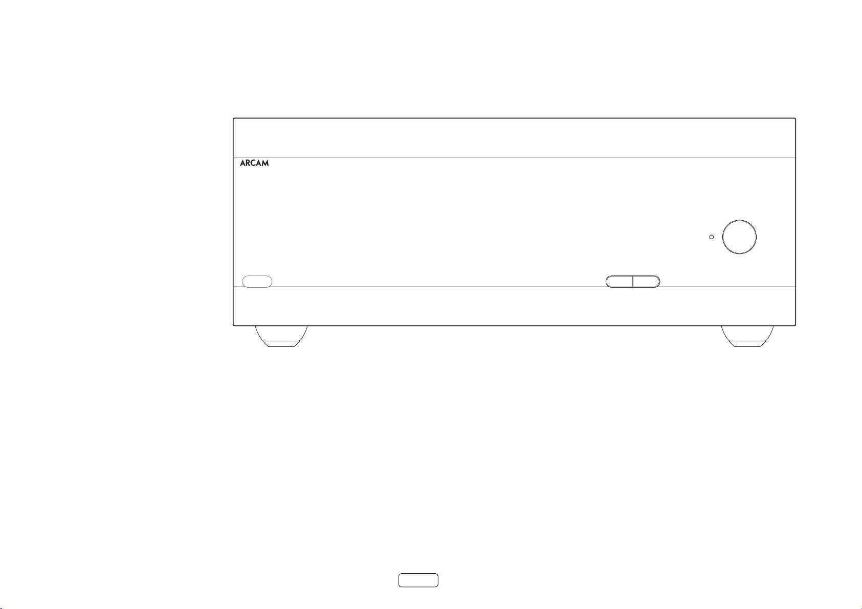
PA720
POWER AMPLIFIER
POWER
STANDBYMUTE
Placing The Unit
Place the amplifier on a level, firm surface, avoiding
direct sunlight and sources of heat or damp.
Do not place the PA720, PA240 or PA410 on top of a
power amplifier or other source of heat.
Do not place the amplifier in an enclosed space such
as a bookcase or closed cabinet unless there is good
provision for ventilation. The PA720, PA240 and PA410
are designed to run warm during normal operation.
Do not place any other component or item on top
of the amplifier as this may obstruct airflow around
the heat-sink, causing the amplifier to run hot. (The
unit placed on top of the amplifier would become
hot, too).
Do not place your record deck on top of this
unit. Record decks are very sensitive to the noise
generated by mains power supplies which will be
heard as a background ‘hum’ if the record deck is too
close.
The normal function of the unit may be disturbed by
strong electromagnetic interference. If this occurs,
simply reset the unit with the power button, or move
the unit to another location.
Interconnect Cables
We recommend the use of high-quality screened cables
that are designed for the particular application. Other
cables will have different impedance characteristics
that will degrade the performance of your system (for
example, do not use cabling intended for video use to
carry audio signals). All cables should be kept as short as
is practically possible.
It is good practice when connecting your equipment to
make sure that the mains power-supply cabling is kept
as far away as possible from your audio cables. Failure to
do so may result in unwanted noise in the audio signals.
EN-6
Power
The amplifier is supplied with a moulded mains plug
already fitted to the lead. Check that the plug supplied
fits your supply – should you require a new mains lead,
please contact your Arcam dealer.
If your mains supply voltage or mains plug is different,
please contact your Arcam dealer immediately.
Push the IEC plug end of the power cable into the power
socket on the back of the amplifier, making sure that it
is pushed in firmly. Plug the other end of the cable into
your mains socket and switch the socket on.
Page 9
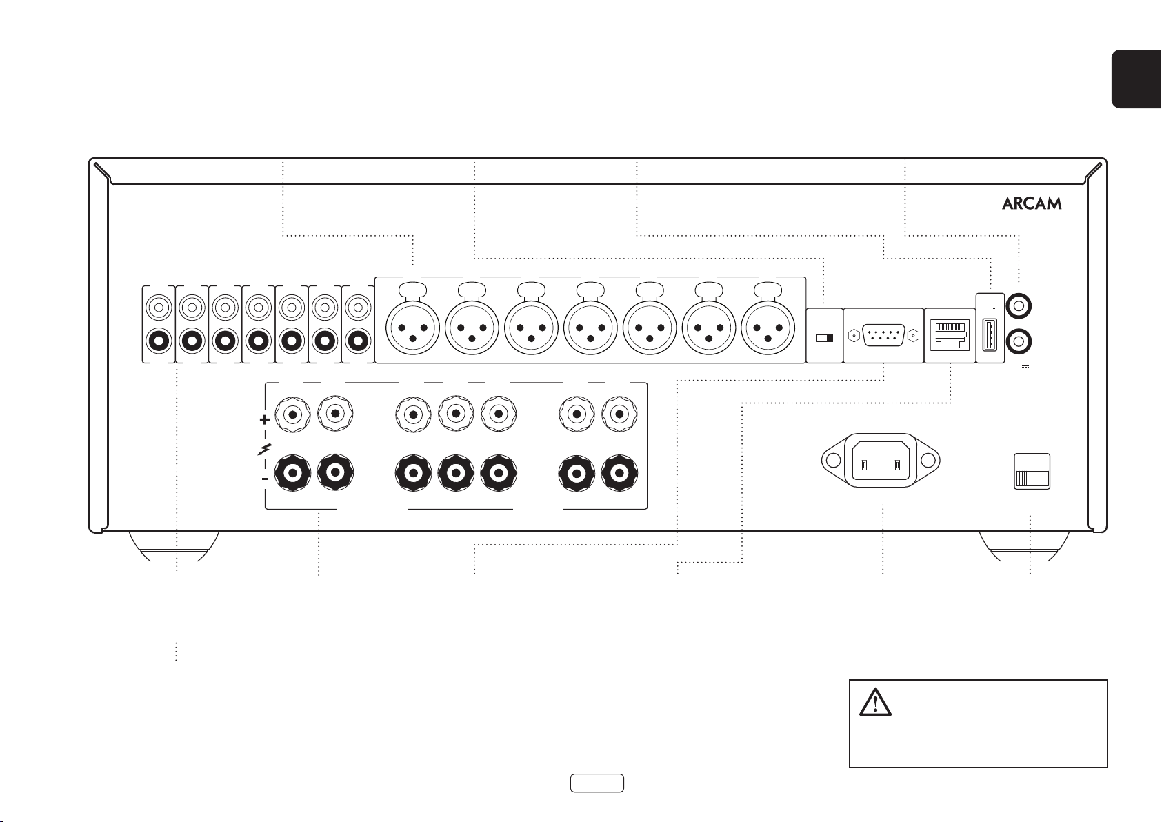
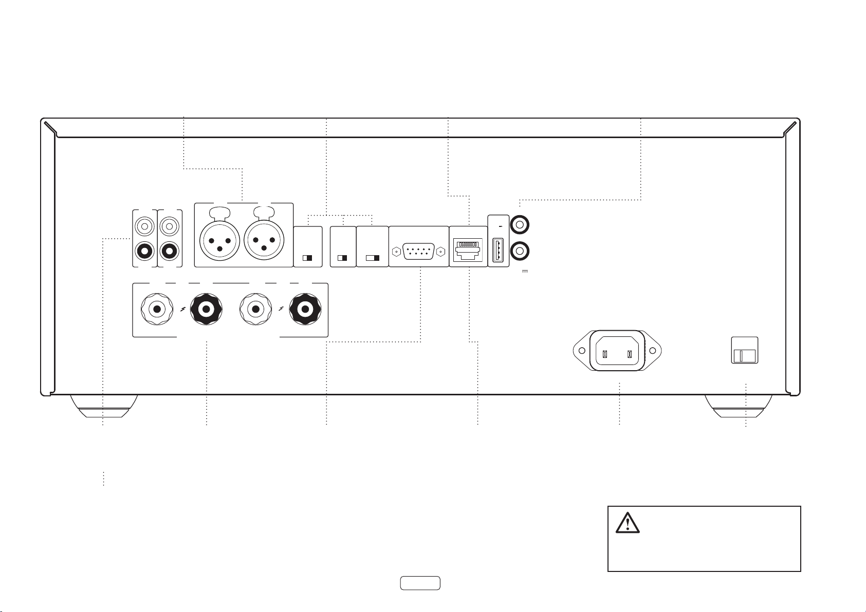
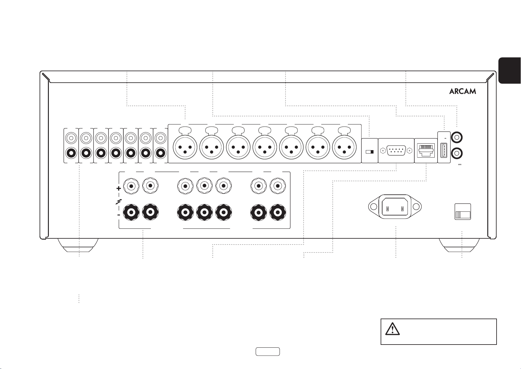
Rear Panel Connections and Controls PA720
IN7
OUT7
BALANCED XLR AUDIO INPUTS
Connect the XLR outputs of your pre-
amplifier.
See “Connecting Sources and
Loudspeakers” on page EN-13.
IN6
IN5
IN4
IN3
IN2
OUT6
OUT5
OUT4
OUT3
OUT2
IN1
OUT1
INPUT SWITCHES
Allow the PA720 to be configured to
different input types
See “Connecting Sources and
Loudspeakers” on page EN-13.
IN7 IN6 IN5 IN4 IN3 IN2 IN1
CH5CH6CH7
CH4 CH3 CH2 CH1
For software upgrades only.
See “USB” on page EN-10.
USB
Trigger OUT allows the PA720 to control the power state of other connected
Trigger IN allows the PA720 to be turned on or off by an external source.
TRIGGER IN / OUT
equipment
See “Trigger IN/OUT” on page EN-10.
TRIGGER IN
USB
5V
100mA
TRIGGER OUT
(12V 100mA)
SUPPLY
VOLTAGE
RCA
INPUT
XLR
RS232 NET
POWER INLET
EN
PRE-AMPLIFIER INPUTS
Connect the phono outputs of your
pre-amplifier.
See “Connecting Sources and
Loudspeakers” on page EN-13.
PRE-AMPLIFIER OUTPUT
OUT1-OUT7 provide a copy of
the signal applied to the IN1-IN7
phono sockets only, not the XLR.
Note: This is a passive output,
no additional filtering or
amplification is applied.
SPEAKER TERMINALS
See “Connecting Sources
and Loudspeakers” on
page EN-13.
4-16 OHMSCLASS 2 WIRING
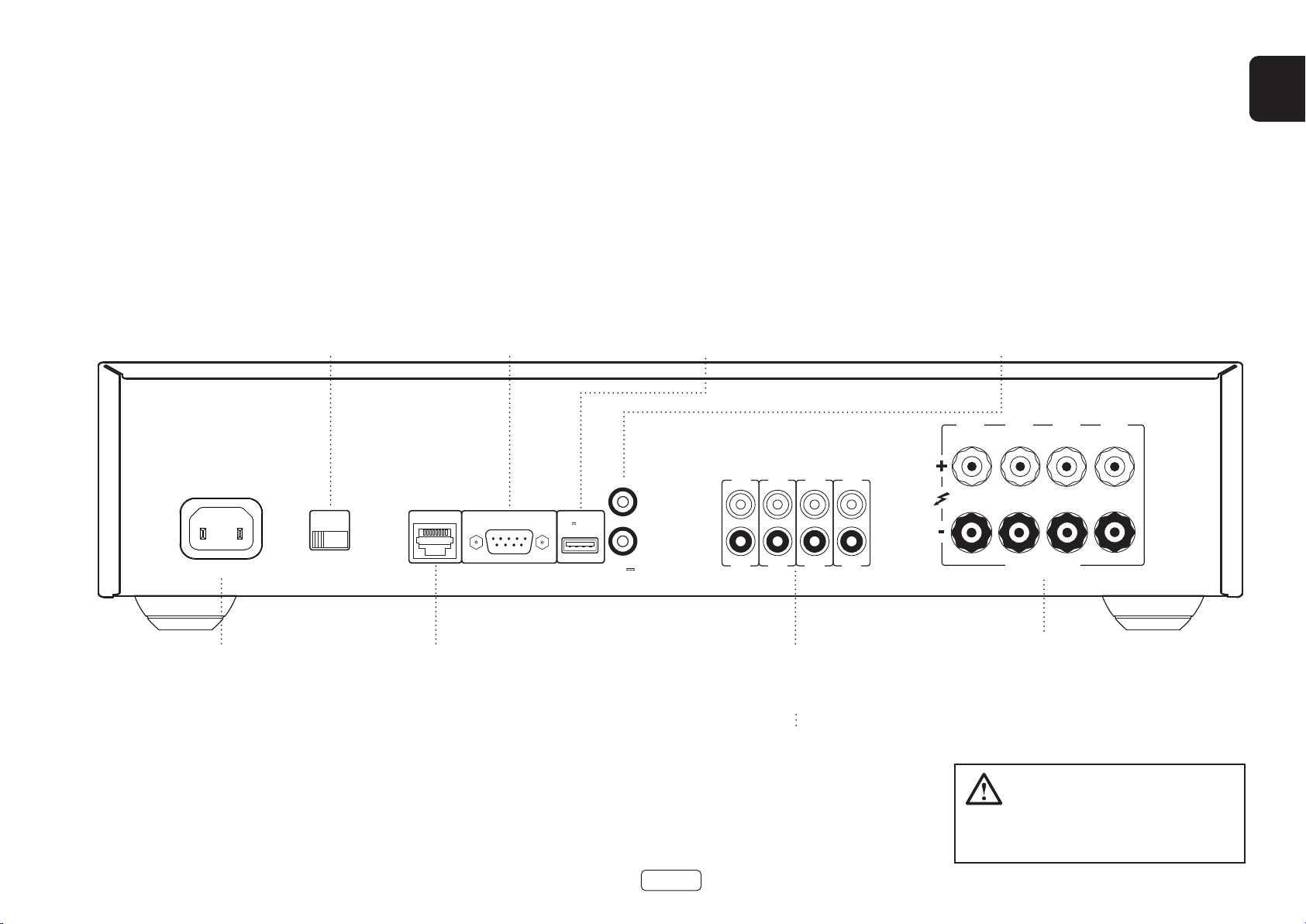
RS232
This connection allows for remote control
from a third-party home automation
system or computer.
See “Network and RS232” on page EN-10.
This connection allows for remote control
NETWORK
from a third-party home automation system or
computer.
See “Network and RS232” on page EN-10.
EN-7
110-120V/220-240V~
50/60Hz 1.5kW MAX
POWER INLET
Connect the correct mains cable
here.
Please read the sections “Placing The Unit”,
“Power” and “Interconnect Cables” on page
EN-6 before connecting your PA720
amplier!
SWITCH POSITIONS
115 = 110 - 120V ~
230 = 220 - 240V ~
VOLTAGE SELECT
Ensure that the voltage
selected matches the local
power supply.
Page 10
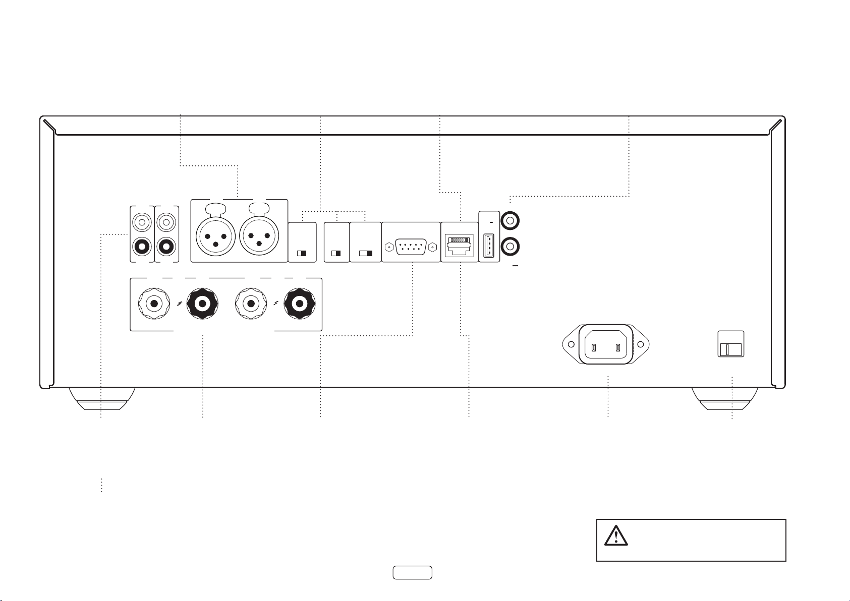
Rear Panel Connections and Controls PA240
RS232 NET
TRIGGER OUT
(12V 100mA)
TRIGGER IN
POWER INLET
110-120V/220-240V~
50/60Hz 1.5kW MAX
USB
5V
100mA
SWITCH POSITIONS
115 = 110 - 120V ~
230 = 220 - 240V ~
SUPPLY
VOLTAGE
RCA
XLR
INPUT
+
4-16 OHMS. CLASS 2 WIRING
+
- -
R
ST BRIDGE DM
GAIN
25dB 31dB
MODE
L
INR INL
INR
OUTR
INL
OUTL
BALANCED XLR AUDIO INPUTS
Connect the XLR outputs of your pre-
amplifier.
See “Connecting Sources and
Loudspeakers” on page EN-13.
INPUT SWITCHES
Allow the PA240 to be configured in
different operational modes.
See “Connecting Sources and
Loudspeakers” on page EN-13.
For software upgrades only.
USB
See “USB” on page EN-10.
Trigger IN allows the PA240 to be turned on or off by an external source.
TRIGGER IN / OUT
Trigger OUT allows the PA240 to control the power state of other connected
equipment
See “Trigger IN/OUT” on page EN-10.
PRE-AMPLIFIER INPUTS
Connect the phono outputs of your
pre-amplifier.
See “Connecting Sources and
Loudspeakers” on page EN-13.
PRE-AMPLIFIER OUTPUT
OUTL and OUTR provide a copy of
the signal applied to the IN L and IN
R phono sockets only, not the XLR.
Note: This is a passive output,
no additional filtering or
amplification is applied.
SPEAKER TERMINALS
See “Connecting Sources
This connection allows for remote control
and Loudspeakers” on
page EN-13.
See “Network and RS232” on page EN-10.
RS232
from a third-party home automation
system or computer.
NETWORK
This connection allows for remote control
from a third-party home automation system or
computer.
See “Network and RS232” on page EN-10.
EN-8
POWER INLET
Connect the correct mains cable
here.
Please read the sections “Placing The Unit”,
“Power” and “Interconnect Cables” on page
EN-6 before connecting your PA240
amplier!
VOLTAGE SELECT
Ensure that the voltage
selected matches the local
power supply.
Page 11
POWER INLET
110-120V/220-240V ~ 50/60Hz
500W MAX
SUPPLY
VOLTAGE
SWITCH POSITIONS
115 = 110 - 120V ~
230 = 220 - 240V ~
RS232NET USB
5V 100mA
CH1
4-16 OHMS
CLASS 2 WIRING
CH2CH3CH4
IN4
OUT4
IN3
OUT3
IN2
OUT2
IN1
OUT1
TRIGGER OUT
(12V 100mA)
TRIGGER IN
Rear Panel Connections and Controls PA410
EN
Connect the correct mains cable
POWER INLET
here.
VOLTAGE SELECT
Ensure that the voltage
selected matches the local
power supply.
Connect your wired local network to one port.
The second port can be used to connect to
See “Network and RS232” on page EN-10.
This connection allows for remote control
RS232
from a third-party home automation
system or computer.
See “Network and RS232” on page EN-10.
NETWORK
other devices
For software upgrades only. See
USB
“USB” on page EN-10.
PRE-AMPLIFIER INPUTS
Connect the phono outputs of your
pre-amplifier.
See “Connecting Sources and
Loudspeakers” on page EN-13.
PRE-AMPLIFIER OUTPUT
OUT1 to OUT4 provide a copy
of the signal applied to the
IN1 to IN4 phono sockets.
Note: This is a passive output,
no additional filtering or
amplification is applied.
EN-9
Trigger IN allows the PA410 to be turned on or off by an external source.
TRIGGER IN / OUT
Trigger OUT allows the PA410 to control the power state of other connected
equipment
See “Trigger IN/OUT” on page EN-10.
SPEAKER TERMINALS
See “Connecting Sources
and Loudspeakers” on
page EN-13.
Please read the sections “Placing The Unit”,
“Power” and “Interconnect Cables” on page
EN-6 before connecting your PA410
amplier!
Page 12
RS232 NET
TRIGGER OUT
(12V 100mA)
TRIGGER IN
POWER INLET
110-120V/220-240V~
50/60Hz 1.5kW MAX
USB
5V
100mA
SWITCH POSITIONS
115 = 110 - 120V ~
230 = 220 - 240V ~
SUPPLY
VOLTAGE
RCA
XLR
INPUT
IN7
OUT7
IN6
OUT6
IN5
OUT5
IN4
OUT4
IN3
OUT3
IN2
OUT2
IN1
OUT1
IN7 IN6 IN5 IN4 IN3 IN2 IN1
CH4 CH3 CH2 CH1
4-16 OHMSCLASS 2 WIRING
CH5CH6CH7
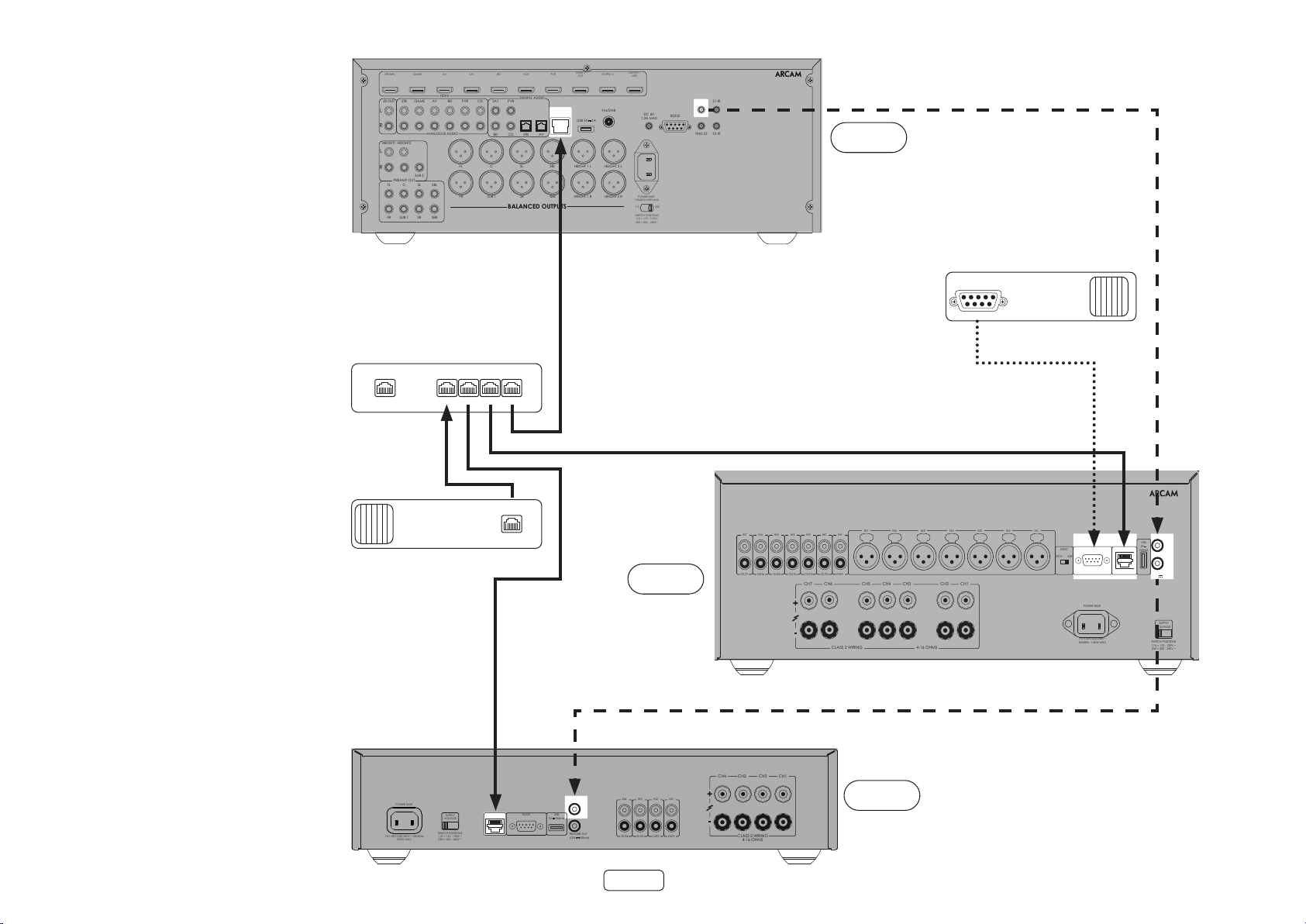
Control System Connections
Network and RS232
The PA720, PA240 and PA410 feature a network and
RS232 port that can be used to connect to a local
network, computer or home automation sytem so that
the amplifier can be controlled and monitored remotely.
Various third party systems are available providing
sophisticated control over all of your entertainment
devices. Contact your dealer or installer for details.
For technical details of control protocols please refer to
the PA720 / PA240 / PA410 RS232/IP control document,
availbale for download at www.arcam.co.uk, for
further information.
Note: By default, network and RS232 control is disabled
in standby to minimise standby power consumption.
To enable network control see “Network and RS322 in
Standby” on page EN-12.
USB
The USB port is used for software updates only. For the
latest software as well as further information, please visit
www.arcam.co.uk.
GAME
STB/MHL
STB
GAME
Z2 OUT
L
R
HEIGHT1 HEIGHT2
L
R
SUB 2
PREAMP OUT
FL C SL SBL
FR SUB 1 SR SBR
Network Router
AV
HDMI
AV
ANALOGUE AUDIO
BD
BD
SAT
PVR
FL C SL SBL HEIGHT 1 L HEIGHT 2 L
FR SUB 1 SR SBR HEIGHT 1 R HEIGHT 2 R
CD
BD CD
VCR
DIGITAL AUDIO
PVRSAT
STB AV
BALANCED OUTPUTS
1 2 3 4NET
NET
PVR
ETHERNET
ZONE 2
OUT
USB 5V
OUTPUT 1
OUTPUT 2
ARC
FM/DAB
DC 6V
1A
1.2A MAX
POWER INLET
~50/60Hz 50W MAX
115 230
SWITCH POSITIONS
115 = 110 - 115V~
230 = 220 - 240V~
TRIG Z1 Z1 IR
RS232
TRIG Z2 Z2 IR
23425
AV860
Home Automation Controller
RS232
Trigger IN/OUT
The power state of the PA720, PA240 and PA410 can
be controlled by compatible audio/video sources
(such as an Arcam AVR). In this case, connect the
TRIGGER OUT of the source to the TRIGGER IN of the
PA720, PA240 or PA410 using a mono 3.5mm jack lead.
Similarly, the PA720, PA240 and PA410 can control the
power state of compatible product (such as another
PA720, PA240 or PA410). In this case, connect the
TRIGGER IN of the source to the TRIGGER OUT of the
PA720, PA240 or PA410 using a mono 3.5mm jack.
Note: These leads are not supplied.
Home Automation Controller
POWER INLET
110-120V/220-240V ~ 50/60Hz
500W MAX
SUPPLY
VOLTAGE
SWITCH POSITIONS
115 = 110 - 120V ~
230 = 220 - 240V ~
RS232NET USB
5V 100mA
TRIGGER IN
TRIGGER OUT
(12V 100mA)
PA720
IN4
IN3
OUT4
OUT3
EN-10
CH2CH3CH4
CH1
IN2
IN1
OUT2
OUT1
CLASS 2 WIRING
4-16 OHMS
PA410
Page 13
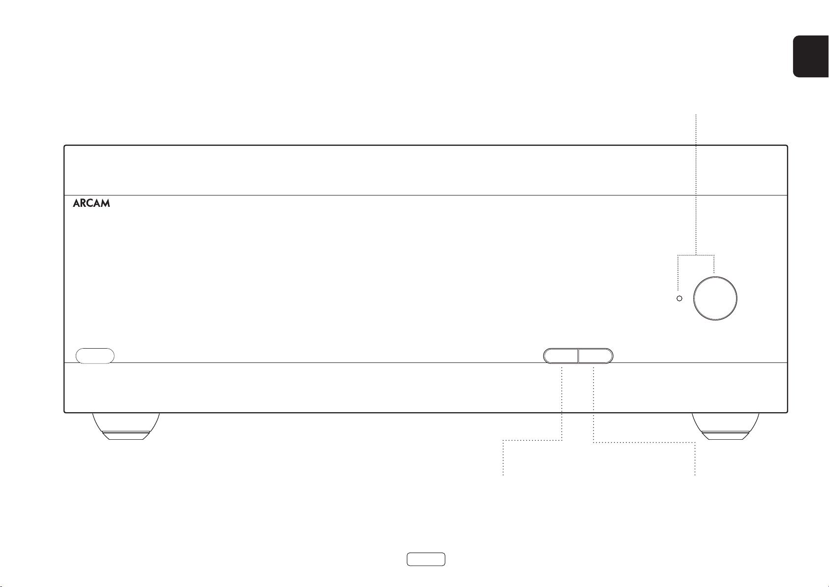
Front Panel Connections and Controls
EN
PA720
POWER INDICATOR AND POWER
SWITCH
See “Switching On” on page EN-12.
POWER AMPLIFIER
POWER
STANDBYMUTE
Mute / unmute the PA720, PA240 or PA410 speaker outputs.
MUTE
See “Muting the Output” on page EN-12.
EN-11
UNIT STANDBY
See “Switching On” on page EN-12.
Page 14

Operation
Switching On
The POWER button switches the unit on and off. The
status indicator LED indicates the state of the amplifier:
it changes from red to orange then white if mains
power is connected and the unit is switched on.
Pressing the STBY button while the unit is powered
on, will place the PA720, PA240 or PA410 into standby
mode. Press the STBY button again to bring the unit out
of standby.
Automatic Standby
In order to comply with international regulations for
consumer products, this unit is designed to enter
standby mode if no user interaction and no audio input
signal are detected for an extended period of time
(default is 20 minutes). The unit can be brought out of
standby by pressing the STBY button on the front panel,
the trigger input or RS232 or ethernet command (if
enabled, see “Network and RS322 in Standby” for more
information)
The standby time out can be adjusted using either
RS232 or IP control commands. Please refer to the
PA720 / PA240 / PA410 RS232/IP control document,
available for download from www.arcam.co.uk.
Alternatively pressing and holding the MUTE button
will toggle the standby time out between OFF and 20
minutes.
The LED will flash to indicate the setting change, red for
OFF, green for 20 minutes.
Note: if the standby time-out is set to OFF, the automatic
standby feature will be disabled.
Network and RS322 in Standby
In low power standby mode the network and RS322
functionality is disabled.
To enable network and RS232 in standby, send a control
or status request command to the unit whilst it is
powered on.
This will enable whichever control method was used
when the unit is in standby.
Note: To indicate the unit is not in lowest power standby
mode the LED will flash briefly when entering standby
mode.
Note: Enabling network or RS232 control will increase
standby power consumption. To restore the unit to
the default low power standby consumption press and
hold the STBY button for more than 3 seconds or restore the unit to
factory defaults.
Muting the Output
The speaker outputs of the PA720, PA240 or PA410 can
be silenced by pressing the MUTE button on either the
front panel or by sending the relevent command via
either the RS232 or network connection.
If the unit is muted, front panel power indicator will
change to orange.
To cancel the mute, press the MUTE button again or
send the relevent command via either the RS232 or
network connection.
Mode switches
The various mode switches located on the rear of the
PA720 and PA240 amplifiers allow you to configure your
power amplifier to your specific equipment setup. See
“Connecting Sources and Loudspeakers” on page EN-13
for more information.
INPUT (PA720 and PA240 only)
This switch selects between the XLR and RCA phono
inputs of the amplifier. Select which ever connection
method you are using to connect your preamp.
GAIN(PA240 only)
This switch allows the gain to be changed from standard
Arcam gain of 31dB (which matches all Arcam amplifiers
and receivers) to 26dB. This allows flexibility to connect
multiple PA240 amplifiers in different modes to multiple
speakers.
In normal set-ups this switch should be left at 31dB.
MODE (PA240 only)
This switch selects between the different amplification
modes of the PA240.
STEREO (ST)
This is the standard stereo amplification mode using
two separate preamp inputs driving two separate
speaker outputs.
DUAL MONO (DM)
This mode allows two separate speakers to be driven
from a single preamp input.
Alternatively the two drivers of a single speaker can be
bi-amped from a single PA240.
EN-12
BRIDGED MONO (BRIDGE)
This mode uses both channels of the PA240 to drive a
single speaker. This the ultimate in high power, high
fidelity amplification.
Page 15
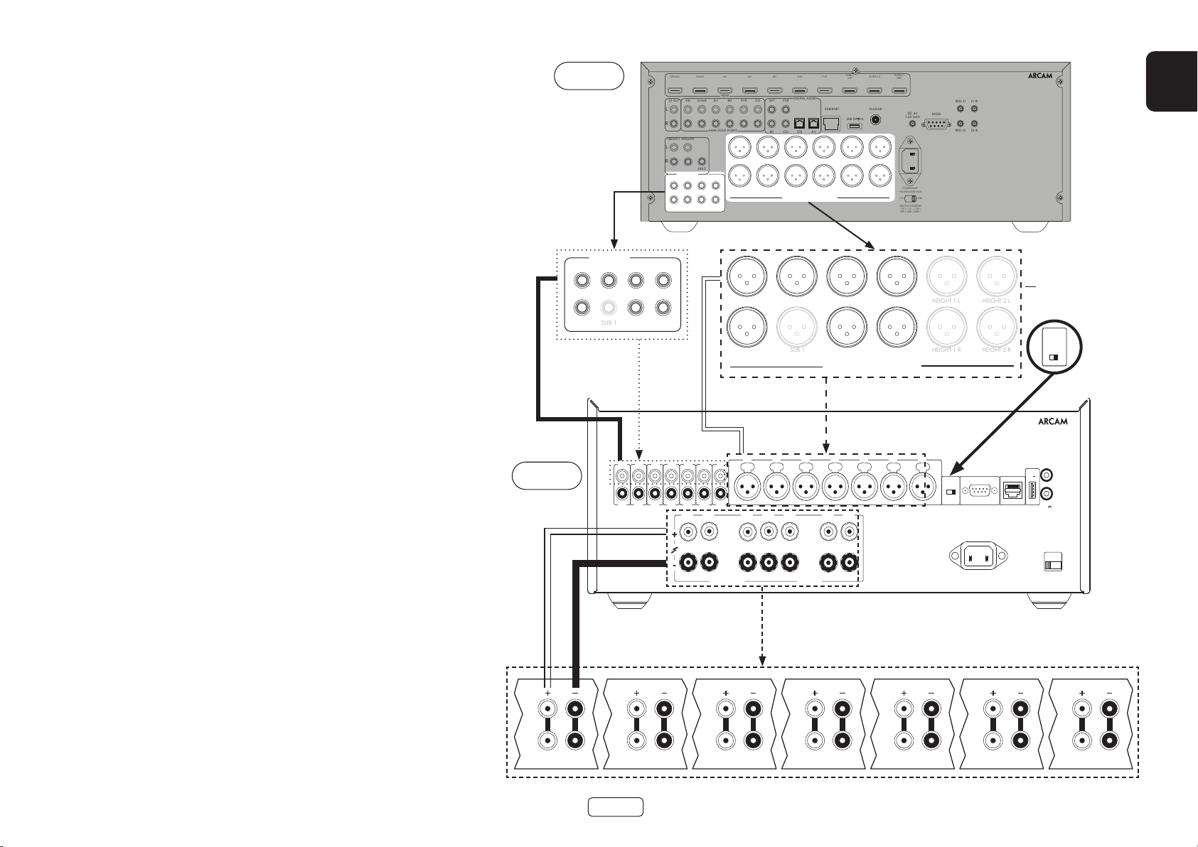
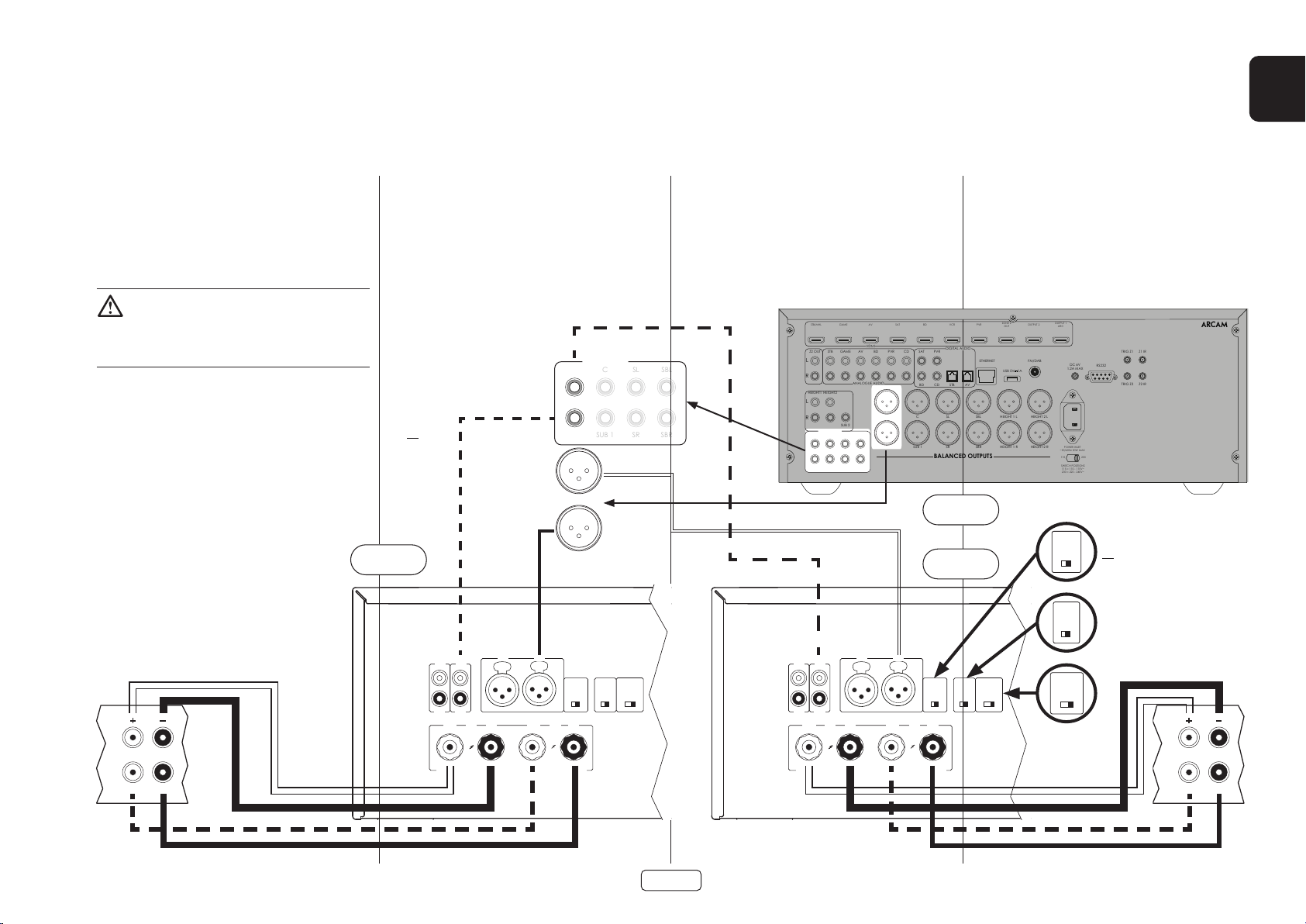
Connecting Sources and Loudspeakers
RS232 NET
TRIGGER OUT
(12V 100mA)
TRIGGER IN
POWER INLET
110-120V/220-240V~
50/60Hz 1.5kW MAX
USB
5V
100mA
SWITCH POSITIONS
115 = 110 - 120V ~
230 = 220 - 240V ~
SUPPLY
VOLTAGE
RCA
XLR
INPUT
IN7
OUT7
IN6
OUT6
IN5
OUT5
IN4
OUT4
IN3
OUT3
IN2
OUT2
IN1
OUT1
IN7 IN6 IN5 IN4 IN3 IN2 IN1
CH4 CH3 CH2 CH1
4-16 OHMSCLASS 2 WIRING
CH5CH6CH7
PREAMP OUT
SUB 1
HEIGHT 1 L
HEIGHT 2 L
SUB 1
HEIGHT 1 R
HEIGHT 2 R
PA720
Connect the RED positive speaker terminal labelled
CH1 to CH7+ to the positive terminal of your speaker.
Similarly, connect the BLACK negative speaker terminal
of the same channel to the negative terminal of your
speaker.
Repeat this process for the other speakers, using the
same respective input and speaker terminals for each
channel.
NOTE: All the channels are identical so there is no
requirement to connect specific AVR output channels
to specific amplifier channels.
AV860
FL C SL SBL
FR
SR SBR
STB/MHL
STB
Z2 OUT
L
R
HEIGHT1 HEIGHT2
L
R
PREAMP OUT
FL C SL SBL
FR SUB 1 SR SBR
GAME
GAME
SUB 2
AV
HDMI
AV
ANALOGUE AUDIO
BD
BD
SAT
CD
PVR
PVRSAT
BD CD
FL C SL SBL HEIGHT 1 L HEIGHT 2 L
FR SUB 1 SR SBR HEIGHT 1 R HEIGHT 2 R
BALANCED OUTPUTS
FL C SL SBL
FR
VCR
DIGITAL AUDIO
STB AV
OUT
ETHERNET
USB 5V
SR SBR
ZONE 2
PVR
BALANCED OUTPUTS
OUTPUT 1
OUTPUT 2
ARC
FM/DAB
DC 6V
1A
1.2A MAX
POWER INLET
~50/60Hz 50W MAX
115 230
SWITCH POSITIONS
115 = 110 - 115V~
230 = 220 - 240V~
TRIG Z1 Z1 IR
RS232
TRIG Z2 Z2 IR
23425
EN
Note: Unit should be
connected via RCA
or XLR. Both versions
shown for illustrative
purposes only.
INPUT
XLR
RCA
Note: Single channel shown for
clarity
Notes On Making Speaker Connections
Do not make any connections to any amplifier while it is switched on. We recommend
that your amplifier is completely disconnected from the mains supply before starting.
Before switching your amplifier on for the first time after connecting to speakers, please
check all connections thoroughly. Ensure that bare wires or cables are not touching
each other or the amplifier’s chassis (which could cause short circuits), and that you
have connected positive (+) to positive and negative (–) to negative. Be sure to check
the wiring for both the amplifier and the speaker.
After making connections: switch the amplifier on then gradually increase the volume
to the required listening level.
If you are unsure as to how your system should be connected, please contact your
Arcam dealer who will be happy to help you.
PA720
HF
LF
HF
LF
EN-13
HF
LF
HF
LF
HF
LF
HF
LF
HF
LF
Page 16
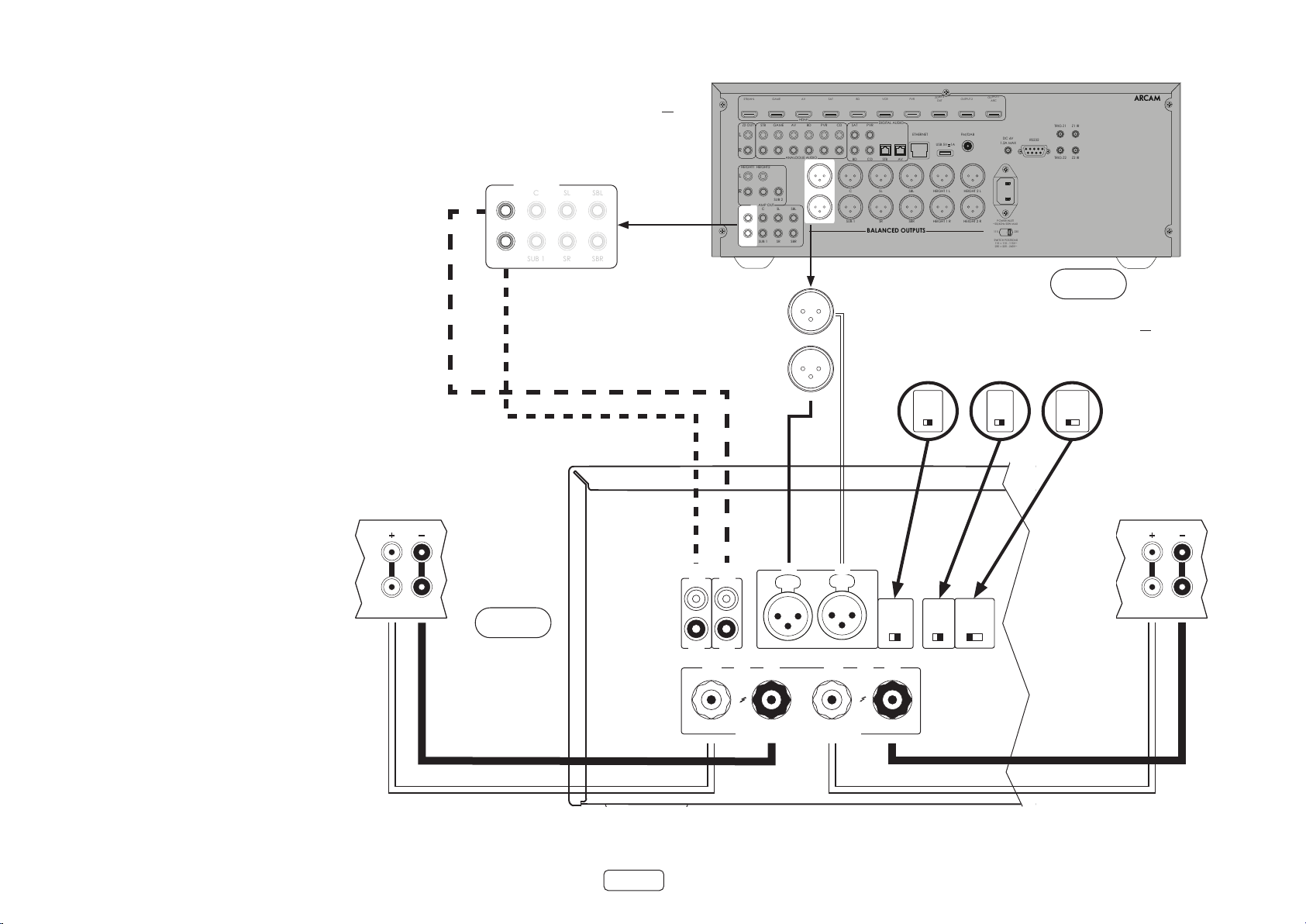
PA240
RCA
XLR
INPUT
+
4-16 OHMS. CLASS 2 WIRING
+
- -
R
ST BRIDGE DM
GAIN
25dB 31dB
MODE
L
INR INL
INR
OUTR
INL
OUTL
PREAMP OUT
CSLSBL
SUB 1SRSBR
Connect the RED positive speaker terminal labelled
L+ to the positive terminal of your speaker. Similarly,
connect the BLACK negative speaker terminal labelled
L to the negative terminal of your speaker.
Note: Unit should be connected via RCA or XLR.
Both versions shown for illustrative purposes
onl y.
FL
FR
STB/MHL
STB
Z2 OUT
L
R
HEIGHT1 HEIGHT2
L
R
PREAMP OUT
FL C SL SBL
FR SUB 1 SR SBR
GAME
GAME
SUB 2
AV
HDMI
AV
ANALOGUE AUDIO
BD
BD
SAT
CD
PVR
PVRSAT
BD CD
FL C SL SBL HEIGHT 1 L HEIGHT 2 L
FR SUB 1 SR SBR HEIGHT 1 R HEIGHT 2 R
BALANCED OUTPUTS
VCR
DIGITAL AUDIO
STB AV
PVR
ETHERNET
ZONE 2
OUT
USB 5V
OUTPUT 1
OUTPUT 2
ARC
FM/DAB
DC 6V
1A
1.2A MAX
POWER INLET
~50/60Hz 50W MAX
115 230
SWITCH POSITIONS
115 = 110 - 115V~
230 = 220 - 240V~
TRIG Z1 Z1 IR
RS232
TRIG Z2 Z2 IR
23425
Repeat this process for the right speaker.
Right
HF
LF
PA240
AV860
Note:
Make sure INPUT switch is set to input type RCA or XLR
FL
Make sure GAIN switch is set to 31dB
Make sure MODE switch is set to stereo mode, ST
FR
GAIN
25dB 31dB
INPUT
XLR
RCA
MODE
ST BRIDGE DM
Left
HF
LF
EN-14
Page 17
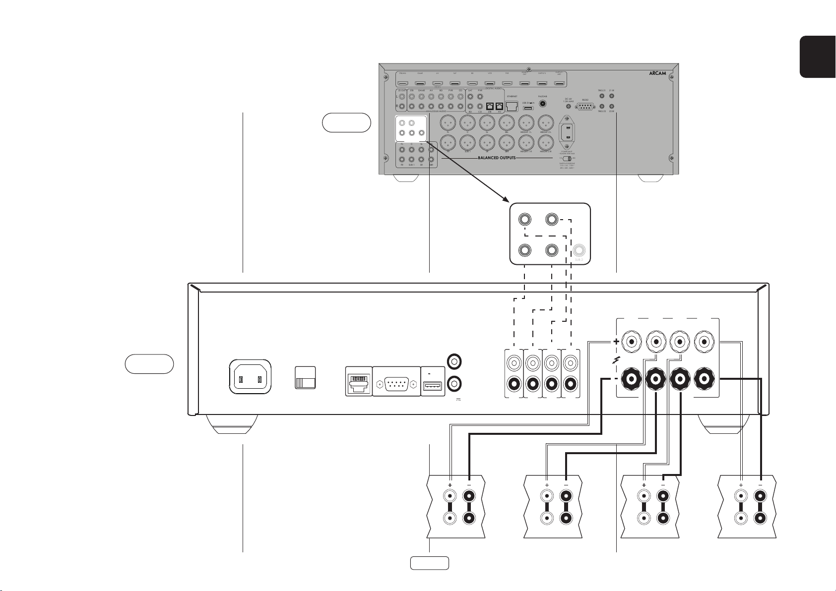
PA410
POWER INLET
110-120V/220-240V ~ 50/60Hz
500W MAX
SUPPLY
VOLTAGE
SWITCH POSITIONS
115 = 110 - 120V ~
230 = 220 - 240V ~
RS232NET USB
5V 100mA
CH1
4-16 OHMS
CLASS 2 WIRING
CH2CH3CH4
IN4
OUT4
IN3
OUT3
IN2
OUT2
IN1
OUT1
TRIGGER OUT
(12V 100mA)
TRIGGER IN
SUB 2
Connect the RED positive speaker terminal labelled
CH1 to CH4+ to the positive terminal of your speaker.
Similarly, connect the BLACK negative speaker terminal
of the same channel- to the negative terminal of your
speaker.
AV860
STB/MHL
STB
Z2 OUT
L
R
HEIGHT1 HEIGHT2
L
R
PREAMP OUT
FL C SL SBL
FR SUB 1 SR SBR
GAME
GAME
SUB 2
AV
HDMI
AV
ANALOGUE AUDIO
BD
BD
SAT
CD
PVR
PVRSAT
BD CD
FL C SL SBL HEIGHT 1 L HEIGHT 2 L
FR SUB 1 SR SBR HEIGHT 1 R HEIGHT 2 R
BALANCED OUTPUTS
VCR
DIGITAL AUDIO
STB AV
ZONE 2
PVR
OUT
ETHERNET
USB 5V
OUTPUT 1
OUTPUT 2
ARC
FM/DAB
DC 6V
1A
1.2A MAX
POWER INLET
~50/60Hz 50W MAX
115 230
SWITCH POSITIONS
115 = 110 - 115V~
230 = 220 - 240V~
TRIG Z1 Z1 IR
RS232
TRIG Z2 Z2 IR
23425
EN
Repeat this process for the other speakers, using the
same respective input and speaker terminals for each
channel.
NOTE: All the channels are identical so there is no
requirement to connect specific AVR output channels
to specific amplifier channels.
PA410
HEIGHT 1 HEIGHT 2
L
R
PREAMP OUT
HF
LF
Height 1 Right Height 1 Left
EN-15
HF
LF
Height 2 Right Height 2 Left
HF
LF
HF
LF
Page 18
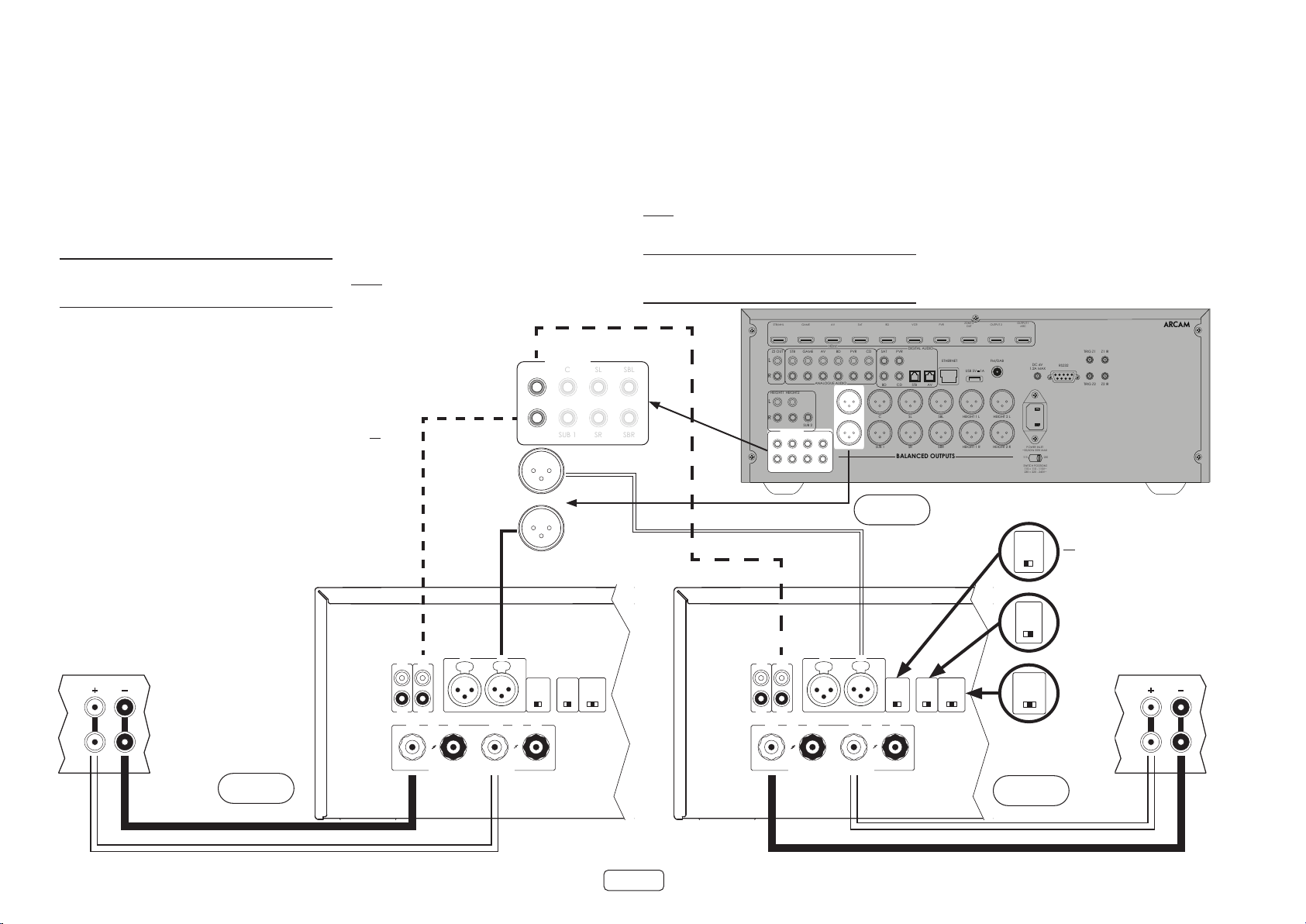
Bridged Mono Mode - PA240
RCA
XLR
INPUT
+
4-16 OHMS. CLASS 2 WIRING
+
- -
R
ST BRIDGE DM
GAIN
25dB 31dB
MODE
L
INR INL
INR
OUTR
INL
OUTL
RCA
XLR
INPUT
+
4-16 OHMS. CLASS 2 WIRING
+
- -
R
ST BRIDGE DM
GAIN
25dB 31dB
MODE
L
INR INL
INR
OUTR
INL
OUTL
PREAMP OUT
CSLSBL
SUB 1SRSBR
only
Bridged mono mode requires the use of a PA240 for
each channel.
Note: In bridged mode only the L+ and R+ speaker
outputs are required.
WARNING: Do not make any connections to the L- or
R- speaker terminals, doing so will severely damage
your amplier.
Note: Unit should be connected via RCA or XLR.
Both versions shown for illustrative purposes
onl y.
Right
HF
On one of the PA240’s, connect the RED positive
speaker terminal labelled L+ to the positive terminal of
your left speaker.
Connect the RED positive speaker terminal labelled R+
to the negative terminal of your left speaker.
Repeat this process for the right speaker, using the
SAME terminals on the other PA240.
FL
FR
FL
FR
Note: L+ must be connected to the positive speaker
terminal and R+ to the negative speaker terminal on
BOTH speakers otherwise the speakers will be out of
phase.
WARNING: Make ABSOLUTELY sure you have used the
L+ and R+ terminals of the PA240. L- and R- terminals
are NOT required in this arrangement.
STB/MHL
STB
Z2 OUT
L
R
HEIGHT1 HEIGHT2
L
R
PREAMP OUT
FL C SL SBL
FR SUB 1 SR SBR
GAME
GAME
SUB 2
AV
HDMI
AV
ANALOGUE AUDIO
BD
BD
SAT
DIGITAL AUDIO
CD
PVR
PVRSAT
BD CD
FL C SL SBL HEIGHT 1 L HEIGHT 2 L
FR SUB 1 SR SBR HEIGHT 1 R HEIGHT 2 R
BALANCED OUTPUTS
AV860
In this setup only one interconnect is required to
each power amplifier and it should be connected to
the IN L input. The interconnects can be either XLR
(recommended for longer cable runs) or phono (RCA).
Set the INPUT switch on both of the PA240’s to the
appropriate setting for the cables used.
Note: The IN R input has no function in this
arrangement.
VCR
STB AV
PVR
ETHERNET
ZONE 2
OUT
USB 5V
OUTPUT 1
OUTPUT 2
ARC
FM/DAB
DC 6V
1A
1.2A MAX
POWER INLET
~50/60Hz 50W MAX
115 230
SWITCH POSITIONS
115 = 110 - 115V~
230 = 220 - 240V~
TRIG Z1 Z1 IR
RS232
TRIG Z2 Z2 IR
Note:
Make sure INPUT switch
25dB 31dB
or XLR
is set to input type RCA
GAIN
It is recommended that the
GAIN switch is set to 25dB
INPUT
XLR
RCA
Make sure MODE switch
is set to bridged mode,
BRIDGE
MODE
ST BRIDGE DM
Left
HF
23425
LF
LF
PA240
PA240
EN-16
Page 19
Dual Mono / Bi Amp Mode - PA240 only
RCA
XLR
INPUT
+ +
- -
R
ST BRIDGE DM
GAIN
25dB 31dB
MODE
L
INR INL
INR
OUTR
INL
OUTL
RCA
XLR
INPUT
+ +
- -
R
ST BRIDGE DM
GAIN
25dB 31dB
MODE
L
INR INL
INR
OUTR
INL
OUTL
PREAMP OUT
CSLSBL
SUB 1SRSBR
EN
Dual mono requires the use of a PA240 for each channel.
On one of the PA240’s, connect the RED positive speaker
terminal labelled L+ to the positive LF terminal of your
left speaker. Similarly, connect the BLACK negative
speaker terminal labelled L- to the negative LF terminal
of your left speaker.
WARNING: Speakers that support biamping
have a metal strip that connects the low
frequency (LF) and high frequency (HF)
terminals. This MUST be removed in a bi-amped
system
Note: Unit should be connected via RCA or XLR.
Both versions shown for illustrative purposes
onl y.
PA240
Right
Using a second speaker cable connect the RED positive
speaker terminal labelled R+ to the positive HF terminal
of your left speaker. Similarly, connect the BLACK
negative speaker terminal labelled R- to the negative
HF terminal of your speaker.
Repeat this process for the right speaker, using the same
terminals on the other PA240.
FL
FR
FL
FR
In this setup only one interconnect is required to
each power amplifier and it should be connected to
the IN L input. The interconnects can be either XLR
(recommended for longer cable runs) or phono (RCA).
Set the INPUT switch on both of the PA240’s to the
appropriate setting for the cables used.
Note: The IN R input has no function in this
arrangement.
STB/MHL
STB
Z2 OUT
L
R
HEIGHT1 HEIGHT2
L
R
PREAMP OUT
FL C SL SBL
FR SUB 1 SR SBR
GAME
GAME
SUB 2
AV
HDMI
AV
ANALOGUE AUDIO
BD
BD
SAT
PVR
FL C SL SBL HEIGHT 1 L HEIGHT 2 L
FR SUB 1 SR SBR HEIGHT 1 R HEIGHT 2 R
CD
VCR
DIGITAL AUDIO
PVRSAT
BD CD
STB AV
BALANCED OUTPUTS
AV860
PA240
ZONE 2
PVR
OUT
ETHERNET
USB 5V
OUTPUT 1
OUTPUT 2
ARC
FM/DAB
DC 6V
1A
1.2A MAX
POWER INLET
~50/60Hz 50W MAX
115 230
SWITCH POSITIONS
115 = 110 - 115V~
230 = 220 - 240V~
TRIG Z1 Z1 IR
RS232
TRIG Z2 Z2 IR
23425
Note:
Make sure INPUT switch
GAIN
25dB 31dB
is set to input type RCA
or XLR
Make sure GAIN switch is
set to 31dB
INPUT
XLR
RCA
Make sure MODE switch
is set to dual mono mode,
DM
MODE
ST BRIDGE DM
Left
HF
LF
HF
LF
EN-17
Page 20

Troubleshooting
Problem Check the following
No sound The PA720 / PA240 / PA410 power amplifier is correctly plugged in and
switched on.
Your audio/video source (e.g. pre amplifier) is correctly connected.
The PA720 / PA240 / PA410 is not in protection mode, as described in
the next section.
The PA720, PA240 and PA410 is not muted.
Sound cuts-out unexpectedly The PA720 / PA240 / PA410 may enter a protection mode, depending on
the fault being detected. The front panel LED will indicate the fault type,
according to the list below.
FLASHING WHITE: The internal temperature of the unit reached an
unsafe level. Allow the PA720 / PA240 / PA410 to cool off.
FLASHING RED: The PA720 / PA240 / PA410 amplifier detected a
speaker short circuit. Should this happen, please inspect all the
speaker cables to make sure none of them are shorted together. This
fault is very common when bare wires are being used to make speaker
connections.
FLASHING ORANGE: PA720 and PA240 only. The amplifier detected a
DC offset.
Following any of the faults described above, the amplifier will turn itself
off and power to the speakers will be removed. To continue using the
PA720 / PA240 / PA410, the fault must be removed and the unit must be
turned OFF then back ON.
EN-18
Page 21
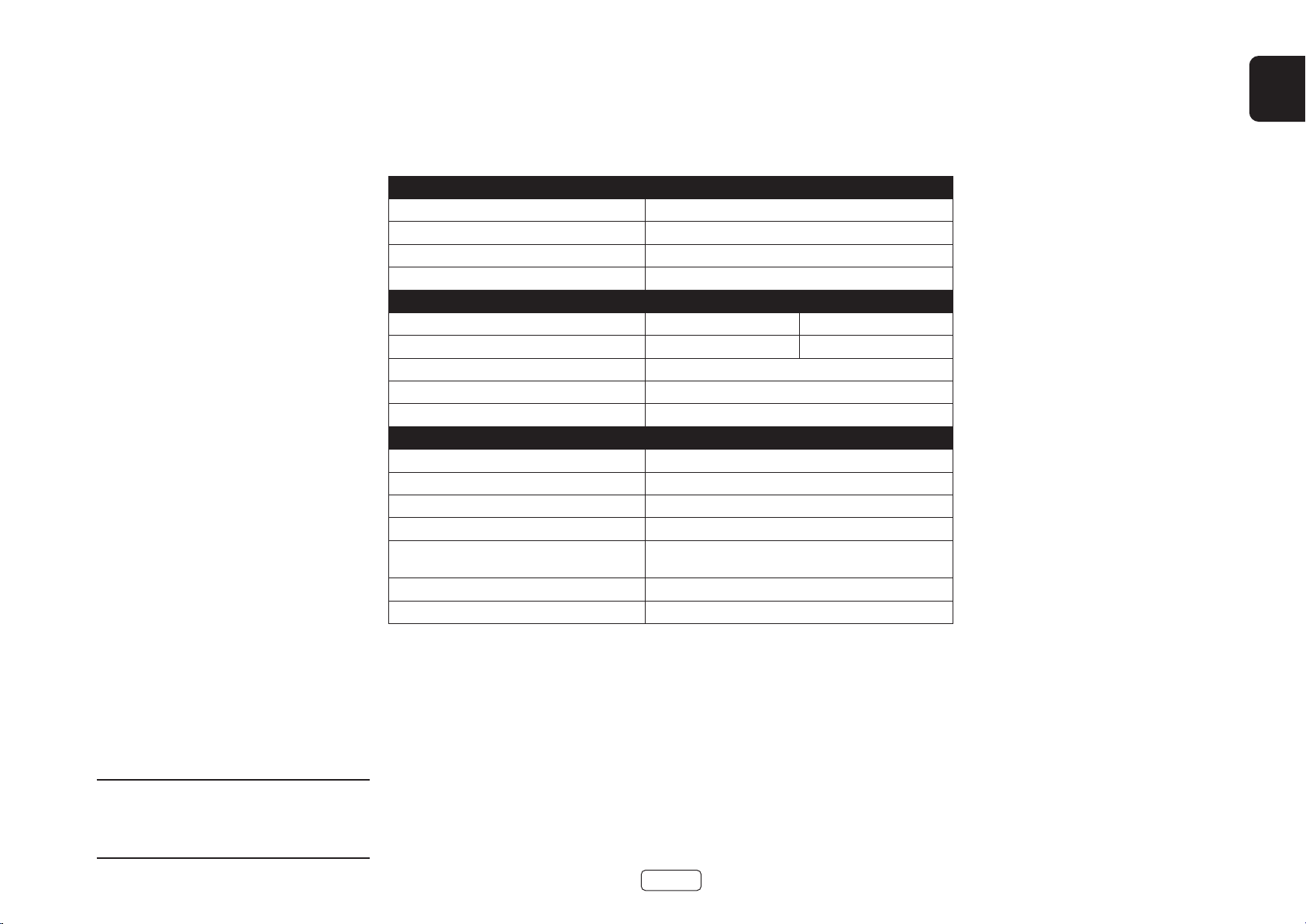
Specications
PA720
Continuous power output at 0.2% THD per channel
Seven channels driven, 4Ω / 8Ω, 1kHz 140W / 100W
Five channels driven, 4Ω / 8Ω, 1kHz 175W / 110W
Two channels driven, 4Ω / 8Ω, 1kHz 225W / 140W
Harmonic distortion, 80% power, 8Ω at 1kHz 0.002%
Inputs
RC A Type XLR Ty pe
Input sensitivity 100W / 8Ω 800mV RMS 1.6V RMS
Signal/Noise ratio (A-wtd) 100W / 8Ω 112dB
Input impedance 10kΩ
Frequency response 20 - 20kHz +/-0.05dB
General
Mains voltage 110–120V or 220–240V, 50–60Hz
Maximum power consumption 1.5kW
Low power standby consumption 0.5W
Network standby consumption 2W
Dimensions W x H x D (including feet,
control knob and speaker terminals)
Weight (net) 18kg
Weight (gross) 19.7kg
433 x 425 x 177mm
EN
All specication values are typical unless otherwise
stated. Arcam has a policy of continuous improvement
for its products. This means that designs and
specications are subject to change without notice.
E&OE.
EN-19
Page 22
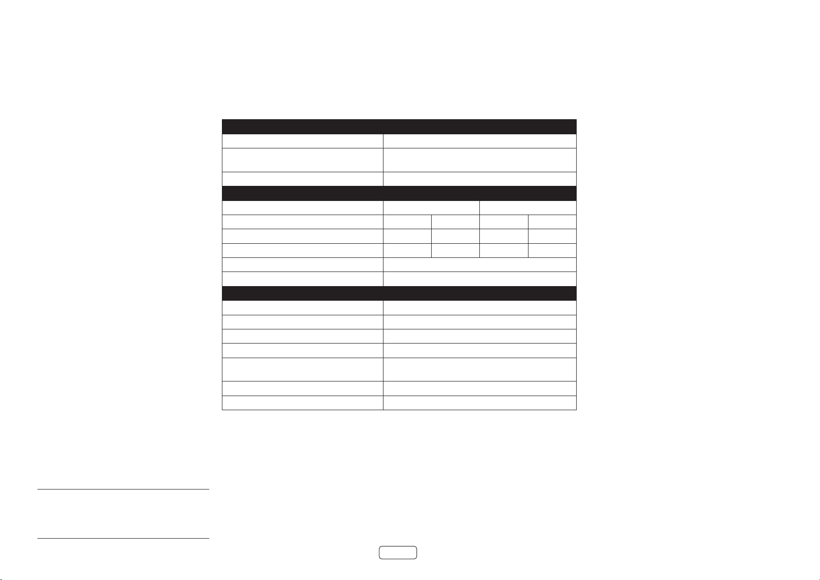
PA240
Continuous power output at 0.2% THD per channel
Two channels driven, 4Ω / 8Ω, 1kHz 380W / 225W
One channel driven,
8Ω bridged mode, 1kHz
Harmonic distortion, 80% power, 8Ω at 1kHz 0.001%
Inputs
Input sensitivity 200W / 8Ω 1.15V RMS 2.3V RMS 2.3V RMS 4.6V RMS
Signal/Noise ratio (A-wtd) 10W / 8Ω 110dB 114dB 110dB 114dB
Input impedance 10kΩ
Frequency response 20 - 20kHz +/-0.05dB
General
Mains voltage 110–120V or 220–240V, 50–60Hz
Maximum power consumption 1.5kW
Low power standby consumption 0.5W
Network standby consumption 2W
Dimensions W x H x D (including feet,
control knob and speaker terminals)
Weight (net) 18kg
Weight (gross) 19.7kg
790W
RC A Type XLR Ty pe
31dB 25dB 31dB 25dB
433 x 425 x 177mm
All specication values are typical unless otherwise
stated. Arcam has a policy of continuous improvement
for its products. This means that designs and
specications are subject to change without notice.
E&OE.
EN-20
Page 23
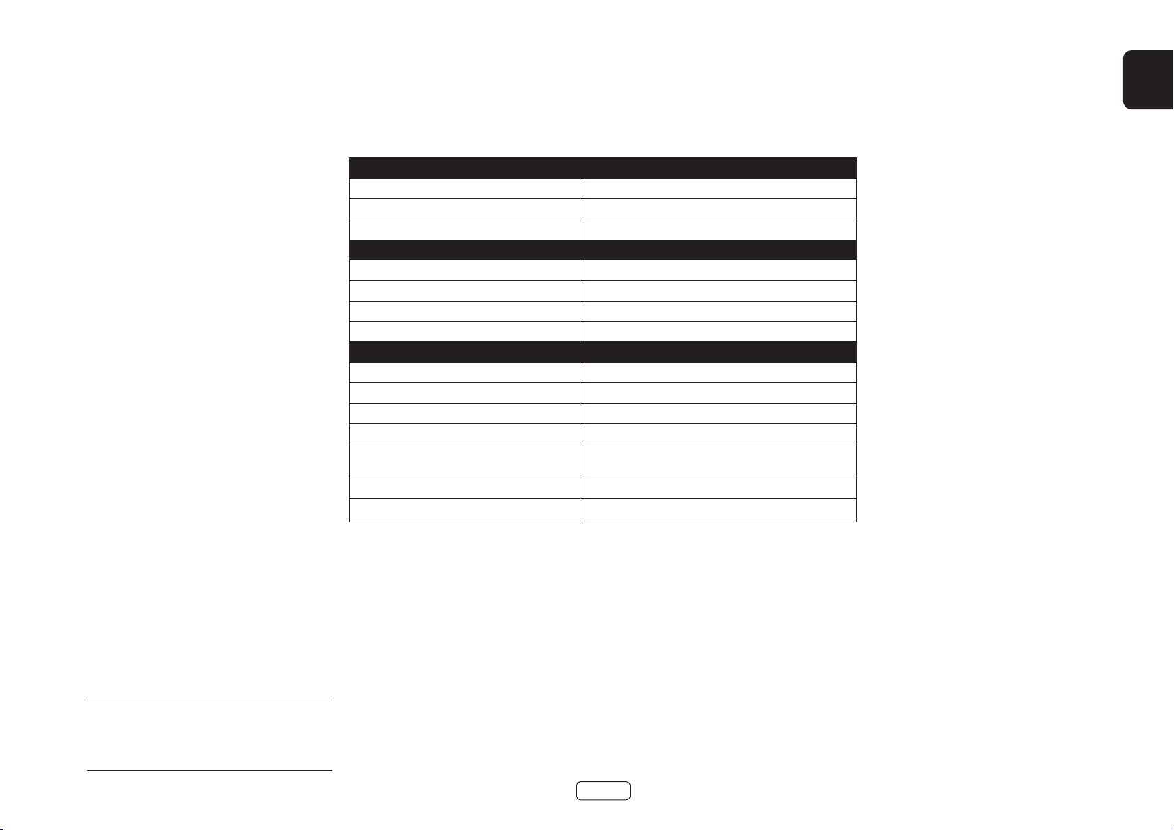
PA410
Continuous power output at at 0.2% THD, per channel
Four channels driven, 4Ω / 8Ω, 1kHz 70W / 50W
Two channels driven, 4Ω / 8Ω, 1kHz 90W / 60W
Harmonic distortion, 80% power, 8Ω at 1kHz 0.003%
Inputs
Input sensitivity 50W / 8Ω 560mV RMS
Signal/Noise ratio (A-wtd) 50W / 8Ω 106dB
Input impedance 10kΩ
Frequency response 20 - 20kHz +/-0.2dB
General
Mains voltage 110–120V or 220–240V, 50–60Hz
Maximum power consumption 700W
Low power standby consumption 0.5W
Network standby consumption 2W
Dimensions W x H x D (including feet,
control knob and speaker terminals)
Weight (net) 10kg
Weight (gross) 11.5kg
433x325x105mm
EN
All specication values are typical unless otherwise
stated. Arcam has a policy of continuous improvement
for its products. This means that designs and
specications are subject to change without notice.
E&OE.
EN-21
Page 24

Worldwide Guarantee
This entitles you to have the unit repaired free of charge, during the first five years after purchase, provided that
it was originally purchased from an authorised Arcam dealer. The Arcam dealer is responsible for all after-sales
service. The manufacturer can take no responsibility for defects arising from accident, misuse, abuse, wear and tear,
neglect or through unauthorised adjustment and/or repair, neither can they accept responsibility for damage or loss
occurring during transit to or from the person claiming under the guarantee.
The warranty covers:
Parts (excluding disc drives) and labour costs for five years from the purchase date (see below for additional terms
and conditions). After five years you must pay for both parts and labour costs.
Disc drives (of any type) are covered under this warranty for two years from the purchase date.
The warranty does not cover battery replacement at any time.
The warranty does not cover transportation costs at any time.
Claims under guarantee
This equipment should be packed in the original packing and returned to the dealer from whom it was purchased.
It should be sent carriage prepaid by a reputable carrier – not by post. No responsibility can be accepted for the unit
whilst in transit to the dealer or distributor and customers are therefore advised to insure the unit against loss or
damage whilst in transit.
For further details contact Arcam at arcam.support@harman.co.uk.
Problems?
If your Arcam dealer is unable to answer any query regarding this or any other Arcam product please contact Arcam
Customer Support at the above address and we will do our best to help you.
On-line registration
You can register your product on-line at www.arcam.co.uk.
EN-22
Page 25

AMPLIFICATEUR
MANUEL
FR
PA720 / PA240 / PA410
Page 26

Bienvenue
Merci et félicitations...
...pour votre achat d’un amplificateur Arcam PA720, PA240 or PA410.
Arcam fabrique des produits audio spécialisés d’une qualité remarquable depuis plus de quatre décennies. Ses plus
récents amplificateurs PA720, PA240 and PA410 sont les derniers d’une longue série de produits de haute-fidélité primés.
La conception de la gamme HDA puise dans toutes les années d’expérience d’Arcam, l’une des sociétés audio les plus
respectées du Royaume-Uni, en vue de produire la famille d’amplificateurs multicanaux la plus performante qu’Arcam ait
jamais conçue et assemblée, et ce pour vous offrir des années de plaisir d’écoute.
Ce manuel est un guide d’installation et d’utilisation du PA720, PA240 and PA410 et contient des informations sur
les fonctionnalités les plus avancées. Utilisez le sommaire de la page suivante pour vous guider vers la section qui
vous intéresse.
Nous espérons que votre produit vous procurera des années de fonctionnement sans problème. Dans le cas peu
probable d’une panne ou si vous avez simplement besoin d’informations complémentaires sur les produits Arcam,
notre réseau de revendeurs se fera un plaisir de vous aider. Vous pouvez trouver des informations plus complètes
sur le site d’Arcam situé au www.arcam.co.uk.
Votre équipe de conception PA720, PA240 and PA410
FR-2
Page 27

Contenu
FR
Bienvenue FR-2
Vue d’ensemble FR-4
Placement de l’unité FR-4
Câbles de raccordement FR-4
Alimentation FR-4
Connexions et commandes du panneau arrière PA720 FR-5
Connexions et commandes du panneau arrière PA240 FR-6
Connexions et commandes du panneau arrière PA410 FR-7
Branchement du système de contrôle FR-8
Réseau et RS232 FR-8
USB FR-8
ENTRÉE/SORTIE de déclenchement FR-8
Commandes et connexions du panneau avant FR-9
Opération FR-10
Mise sous alimentation FR-10
Veille automatique FR-10
Réseau et RS322 en mode veille FR-10
Désactivation du son de la sortie FR-10
Commutateurs de modes FR-10
Branchement des sources et des enceintes acoustiques FR-11
Mode ponté mono – PA240 seulement FR-14
Mono double/Mode Bi Amp – PA240 seulement FR-15
Dépannage FR-16
Caractéristiques techniques FR-17
PA720 FR-17
PA240 FR-18
PA410 FR-19
Garantie Internationale FR-20
FR-3
Page 28

Vue d’ensemble
Les amplicateurs Arcam
PA720, PA240 and PA410
Les amplificateurs Arcam PA720, PA240 and PA410
offrent une qualité sonore de premier ordre pour une
reproduction optimale de votre musique.
Ces amplificateurs, fruits de nombreuses années
d’expérience d’Arcam en conception d’éléments
d’amplification, utilisent les meilleurs composants et
les meilleures pratiques d’ingénierie pour produire des
amplificateurs qui offriront de nombreuses années de
plaisir musical et une opération fiable.
Avec une alimentation toroïdale, un châssis à
amortissement acoustique, une technologie de
classe G (PA240 et PA720), des étages de sortie à
transistors parallèles (PA240) et des niveaux de distorsion
et de bruit exceptionnellement bas, ces amplificateurs
PA720, PA240 and PA410 sont tous capables de
reproduire la musique avec toute son autorité et ses
détails originaux. Soyez assuré que vous entendrez la
musique comme l’artiste l’a prévu.
Les amplificateurs PA720, PA240 and PA410 sont conçus
pour produire un niveau de performance qui donnera
vie à la musique.
Placement de l’unité
Posez l’amplificateur sur une surface plane et ferme,
en évitant les rayons directs du soleil et les sources de
chaleur ou d’humidité.
Ne le placez pas le PA720, PA240 or PA410 sur un
amplificateur ou une autre source de chaleur.
Ne placez pas l’amplificateur dans un endroit fermé
comme une bibliothèque ou un meuble fermé à
moins qu’il n’y ait une bonne circulation d’air. Le
PA720, PA240 and PA410 est conçu pour produire de
la chaleur lors de son fonctionnement normal.
Ne placez aucun autre composant ou article sur le
dessus de l’amplificateur, car cela pourrait obstruer
la circulation d’air autour du dissipateur thermique
et provoquer un échauffement de l’amplificateur.
(L’appareil placé sur le dessus de l’amplificateur
deviendrait également chaud).
PA720
Ne placez pas votre platine tourne-disques sur
cet appareil. Les platines tourne-disques sont très
sensibles au bruit généré par l’alimentation secteur
qui sera entendu comme un « bourdonnement » de
fond si le tourne-disque est trop proche.
L’opération normale de l’appareil peut être perturbée
par de fortes interférences électromagnétiques. Si
cela se produit, réinitialisez simplement l’appareil à
l’aide du bouton d’alimentation ou déplacez-le à un
autre endroit.
Câbles de raccordement
Nous recommandons l’utilisation de câbles blindés de
haute qualité, conçus pour l’application particulière.
D’autres câbles auront des caractéristiques d’impédance
différentes qui réduiront les performances de votre
système (par exemple, n’utilisez pas de câbles destinés
à la vidéo pour transporter des signaux audio). Tous les
câbles doivent être aussi courts que possible.
Il est recommandé, lors du branchement de votre
équipement, de veiller à ce que le câblage de
l’alimentation secteur soit aussi éloigné que possible
de vos câbles audio. Le défaut à suivre ces règles peut
entraîner des bruits indésirables dans les signaux audio.
POWER AMPLIFIER
POWER
STANDBYMUTE
Alimentation
L’amplificateur est livré avec une fiche secteur moulée
déjà montée sur le câble. Vérifiez que la fiche fournie
correspond à votre type d’alimentation – si vous avez
besoin d’un nouveau câble secteur, veuillez contacter
votre revendeur Arcam.
Si la tension d’alimentation de la prise secteur ou la fiche
de votre appareil ne conviennent pas, veuillez contacter
immédiatement votre revendeur Arcam.
Enfoncez l’extrémité de la fiche CEI du câble
d’alimentation dans la prise de courant située à l’arrière
de l’amplificateur, en vous assurant qu’elle est bien
enfoncée. Branchez l’autre extrémité du câble dans
votre prise secteur et mettez l’interrupteur à la position
EN MARCHE.
FR-4
Page 29
Connexions et commandes du panneau arrière PA720
ENTRÉES AUDIO XLR SYMÉTRIQUES
Branchez les sorties XLR de votre
préamplificateur.
Consultez le « Branchement des sources et des
enceintes acoustiques » sur la page FR-11.
COMMUTATEURS D’ENTRÉES
Permettent de configurer le PA720 pour
différents types d’entrée
Consultez le « Branchement des sources et des
enceintes acoustiques » sur la page FR-11.
USB
Pour les mises à jour
logicielles seulement.
Consultez le « USB » sur la
page FR-8.
L’ENTRÉE de déclenchement permet d’activer ou de mettre le PA720 sous tension ou
ENTRÉE/SORTIE DE DÉCLENCHEMENT
hors tension à partir d’une source externe.
La SORTIE de déclenchement du PA720 permet de contrôler l’alimentation d’autres
appareils branchés.
Consultez le « ENTRÉE/SORTIE de déclenchement » sur la page FR-8.
FR
IN7
IN6
IN5
OUT7
OUT6
OUT5
ENTRÉES PRÉAMPLIFICATEUR
Branchez les sorties phono de votre
préamplificateur.
Consultez le « Branchement des
sources et des enceintes acoustiques »
sur la page FR-11.
SORTIE PRÉAMPLIFICATEUR
Les sorties OUT1-OUT7 fournit une
copie du signal aux prises phono
IN1-IN7 uniquement, et non au XLR.
Note: Il s’agit d’une sortie passive :
aucun filtrage ou amplification
supplémentaire ne sont appliqués.
IN4
IN3
IN2
OUT4
OUT3
OUT2
BORNES DE
HAUT-PARLEUR
Consultez le «
Branchement des
sources et des
enceintes acoustiques »
sur la page FR-11.
IN1
OUT1
IN7 IN6 IN5 IN4 IN3 IN2 IN1
CH5CH6CH7
CH4 CH3 CH2 CH1
RS232
Cette connexion permet le contrôle
à distance à partir d’un système
domotique ou d’un ordinateur tiers.
Consultez le « Réseau et RS232 » sur la
page FR-8.
TRIGGER IN
USB
INPUT
XLR
RCA
4-16 OHMSCLASS 2 WIRING
Cette connexion permet le contrôle
RÉSEAU
à distance à partir d’un système
ENTRÉE D’ALIMENTATION
Branchez le câble secteur approprié
dans la prise marquée POWER INLET.
RS232 NET
POWER INLET
110-120V/220-240V~
50/60Hz 1.5kW MAX
domotique ou d’un ordinateur tiers.
5V
100mA
TRIGGER OUT
(12V 100mA)
SUPPLY
VOLTAGE
SWITCH POSITIONS
115 = 110 - 120V ~
230 = 220 - 240V ~
SÉLECTION DE LA TENSION
Assurez-vous que la tension
sélectionnée correspond à la
tension d’alimentation locale.
Consultez le « Réseau et RS232 » sur la
page FR-8.
Veuillez consulter les sections « Placement
de l’unité », « Alimentation » et « Câbles de
raccordement » à la page FR-4 avant de
brancher votre PA720 amplicateur!
FR-5
Page 30
Connexions et commandes du panneau arrière PA240
RS232 NET
TRIGGER OUT
(12V 100mA)
TRIGGER IN
POWER INLET
110-120V/220-240V~
50/60Hz 1.5kW MAX
USB
5V
100mA
SWITCH POSITIONS
115 = 110 - 120V ~
230 = 220 - 240V ~
SUPPLY
VOLTAGE
RCA
XLR
INPUT
+
4-16 OHMS. CLASS 2 WIRING
+
- -
R
ST BRIDGE DM
GAIN
25dB 31dB
MODE
L
INR INL
INR
OUTR
INL
OUTL
ENTRÉES AUDIO XLR SYMÉTRIQUES
Branchez les sorties XLR de votre
préamplificateur.
Consultez le « Branchement des sources et des
enceintes acoustiques » sur la page FR-11.
COMMUTATEURS D’ENTRÉES
Permettent de configurer le PA240 en divers
modes d’opération.
Consultez le « Branchement des sources et des
enceintes acoustiques » sur la page FR-11.
USB
Pour les mises à jour
logicielles seulement.
Consultez le « USB » sur
la page FR-8.
L’ENTRÉE de déclenchement permet d’activer ou de mettre le PA240 sous tension ou
ENTRÉE/SORTIE DE DÉCLENCHEMENT
hors tension à partir d’une source externe.
La SORTIE de déclenchement du PA240 permet de contrôler l’alimentation d’autres
appareils branchés.
Consultez le « ENTRÉE/SORTIE de déclenchement » sur la page FR-8.
ENTRÉES PRÉAMPLIFICATEUR
Branchez les sorties phono de votre
préamplificateur.
Consultez le « Branchement des
sources et des enceintes acoustiques »
sur la page FR-11.
SORTIE PRÉAMPLIFICATEUR
OUTL et OUTR fournissent une copie
du signal aux prises phono IN L et
IN R uniquement, et non au XLR.
Note: Il s’agit d’une sortie passive :
aucun filtrage ou amplification
supplémentaire ne sont appliqués.
BORNES DE
HAUT-PARLEUR
Consultez le « Branchement
des sources et des enceintes
acoustiques » sur la page
FR-11.
RS232
Cette connexion permet le contrôle
à distance à partir d’un système
domotique ou d’un ordinateur tiers.
Consultez le « Réseau et RS232 » sur la
page FR-8.
RÉSEAU
Cette connexion permet le contrôle à
distance à partir d’un système domotique
ou d’un ordinateur tiers.
Consultez le « Réseau et RS232 » sur la
page FR-8.
FR-6
ENTRÉE D’ALIMENTATION
Branchez le câble secteur approprié
dans la prise marquée POWER INLET.
Veuillez consulter les sections « Placement
de l’unité », « Alimentation » et « Câbles de
raccordement » à la page FR-4 avant de
brancher votre PA240 amplicateur!
SÉLECTION DE LA TENSION
Assurez-vous que la tension
sélectionnée correspond à la
tension d’alimentation locale.
Page 31

POWER INLET
110-120V/220-240V ~ 50/60Hz
500W MAX
SUPPLY
VOLTAGE
SWITCH POSITIONS
115 = 110 - 120V ~
230 = 220 - 240V ~
RS232NET USB
5V 100mA
CH1
4-16 OHMS
CLASS 2 WIRING
CH2CH3CH4
IN4
OUT4
IN3
OUT3
IN2
OUT2
IN1
OUT1
TRIGGER OUT
(12V 100mA)
TRIGGER IN
Connexions et commandes du panneau arrière PA410
FR
ENTRÉE D’ALIMENTATION
Branchez le câble secteur approprié
dans la prise marquée POWER INLET.
SÉLECTION DE LA TENSION
Assurez-vous que la tension
sélectionnée correspond à la
tension d’alimentation locale.
Connectez votre réseau local câblé à un
port. Le deuxième port peut être utilisé
pour se connecter à d’autres appareils
Consultez le « Réseau et RS232 » sur la
RS232
Cette connexion permet le
contrôle à distance à partir d’un système
domotique ou d’un ordinateur tiers.
Consultez le « Réseau et RS232 » sur la
page FR-8.
RÉSEAU
page FR-8.
Pour les mises à jour logicielles
USB
seulement. Consultez le « USB »
sur la page FR-8.
ENTRÉES PRÉAMPLIFICATEUR
Branchez les sorties phono de votre
préamplificateur.
Consultez le « Branchement des sources et des
enceintes acoustiques » sur la page FR-11.
SORTIE PRÉAMPLIFICATEUR
OUT1 à OUT4 fournissent une
copie du signal appliqué aux
prises phono IN1 à IN4.
Note: Il s’agit d’une sortie passive :
aucun filtrage ou amplification
supplémentaire ne sont appliqués.
FR-7
L’ENTRÉE de déclenchement permet d’activer ou de mettre le PA410 sous tension
ENTRÉE/SORTIE DE DÉCLENCHEMENT
ou hors tension à partir d’une source externe.
La SORTIE de déclenchement du PA410 permet de contrôler l’alimentation
d’autres appareils branchés.
Consultez le « ENTRÉE/SORTIE de déclenchement » sur la page FR-8.
BORNES DE
HAUT-PARLEUR
Consultez le « Branchement
des sources et des enceintes
acoustiques » sur la page FR-11.
Veuillez consulter les sections « Placement
de l’unité », « Alimentation » et « Câbles de
raccordement » à la page FR-4 avant de
brancher votre PA410 amplicateur!
Page 32

RS232 NET
TRIGGER OUT
(12V 100mA)
TRIGGER IN
POWER INLET
110-120V/220-240V~
50/60Hz 1.5kW MAX
USB
5V
100mA
SWITCH POSITIONS
115 = 110 - 120V ~
230 = 220 - 240V ~
SUPPLY
VOLTAGE
RCA
XLR
INPUT
IN7
OUT7
IN6
OUT6
IN5
OUT5
IN4
OUT4
IN3
OUT3
IN2
OUT2
IN1
OUT1
IN7 IN6 IN5 IN4 IN3 IN2 IN1
CH4 CH3 CH2 CH1
4-16 OHMSCLASS 2 WIRING
CH5CH6CH7
Branchement du système de
contrôle
Réseau et RS232
Le PA720, PA240 and PA410 dispose d’un port réseau et
RS232 qui peut être utilisé pour se connecter à un réseau
local, à un ordinateur ou à un système domotique afin
que l’amplificateur puisse être contrôlé à distance.
Différents systèmes tiers sont disponibles et offrent
un contrôle sophistiqué sur tous vos appareils de
divertissement. Contactez votre revendeur ou votre
installateur pour plus de détails.
Pour les détails techniques des protocoles de contrôle,
veuillez vous référer au document de contrôle RS232/IP
de PA720 / PA240 / PA410 disponible en téléchargement
sur www.arcam.co.uk, pour plus d’informations.
Note: La commande réseau et RS232 est désactivée
par défaut en mode veille pour minimiser la
consommation d’énergie en mode veille. Pour activer
le contrôle réseau, voir « Réseau et RS322 en mode
veille » sur la page FR-10.
USB
Le port USB est utilisé uniquement pour les mises à jour
logicielles. Pour obtenir les logiciels les plus récents ainsi
que de plus amples informations, veuillez consulter le
site www.arcam.co.uk.
ENTRÉE/SORTIE de déclenchement
L’état d’alimentation du PA720, PA240 and PA410 peut
être contrôlé par des sources audio/vidéo compatibles
(comme un récepteur audio-vidéo Arcam). Dans ce cas,
branchez le TRIGGER OUT de la source au TRIGGER IN
du PA720, PA240 or PA410 en utilisant un fil à mini-prise
3,5 mm mono.
De même, le PA720, PA240 and PA410 peut contrôler
l’état d’alimentation d’un produit compatible (comme
un autre PA720, PA240 or PA410). Dans ce cas, branchez
le TRIGGER IN de la source au TRIGGER OUT du
PA720, PA240 or PA410 en utilisant un fil à mini-prise
3,5 mm mono.
Note: Ces câbles ne sont pas fournis.
GAME
STB/MHL
AV
STB
GAME
Z2 OUT
L
R
L
R
HEIGHT1 HEIGHT2
SUB 2
PREAMP OUT
FL C SL SBL
FR SUB 1 SR SBR
ANALOGUE AUDIO
Routeur réseau
Contrôleur domotique
POWER INLET
110-120V/220-240V ~ 50/60Hz
500W MAX
AV
HDMI
BD
BD
SAT
CD
PVR
BD CD
FL C SL SBL HEIGHT 1 L HEIGHT 2 L
FR SUB 1 SR SBR HEIGHT 1 R HEIGHT 2 R
PVR
VCR
DIGITAL AUDIO
PVRSAT
ETHERNET
STB AV
BALANCED OUTPUTS
1 2 3 4NET
NET
SUPPLY
VOLTAGE
SWITCH POSITIONS
115 = 110 - 120V ~
230 = 220 - 240V ~
RS232NET USB
5V 100mA
ZONE 2
TRIGGER IN
TRIGGER OUT
(12V 100mA)
OUTPUT 1
OUTPUT 2
OUT
USB 5V
ARC
FM/DAB
DC 6V
1A
1.2A MAX
POWER INLET
~50/60Hz 50W MAX
115 230
SWITCH POSITIONS
115 = 110 - 115V~
230 = 220 - 240V~
TRIG Z1 Z1 IR
RS232
TRIG Z2 Z2 IR
23425
AV860
Contrôleur domotique
RS232
PA720
CH2CH3CH4
CH1
IN4
IN3
IN2
OUT4
FR-8
IN1
OUT3
OUT2
OUT1
CLASS 2 WIRING
4-16 OHMS
PA410
Page 33

Commandes et connexions du panneau avant
INDICATEUR D’ALIMENTATION
ET INTERRUPTEUR
D’ALIMENTATION
Consultez le « Mise sous
alimentation » sur la page FR-10.
FR
POWER AMPLIFIER
PA720
Désactiver/rétablir PA720, PA240 or PA410 le son des
SOURDINE
sorties haut-parleurs.
Consultez le « Désactivation du son de la sortie » sur la
page FR-10.
FR-9
POWER
STANDBYMUTE
MISE EN VEILLE DE L’APPAREIL
Consultez le « Mise sous alimentation » sur la page FR-10.
Page 34

Opération
Mise sous alimentation
La touche POWER active et désactive l’appareil. La DEL
d’indication d’état indique l’état de l’amplificateur : elle
passe du rouge à l’orange puis au blanc si l’alimentation
secteur est branchée et que l’appareil est allumé.
Appuyez sur la touche STBY lorsque l’appareil est sous
tension pour le mettre PA720, PA240 or PA410 en mode
veille. Appuyez sur la touche STBY de nouveau pour le
sortir du mode veille.
Veille automatique
Afin de se conformer aux réglementations internationales
relatives aux produits de consommation, cet appareil
est conçu pour passer en mode veille si aucune
interaction de l’utilisateur et aucun signal d’entrée
audio n’est détecté pendant une période prolongée (20
minutes par défaut). L’appareil peut être mis hors veille
en appuyant sur le touche STBY sur le panneau avant,
par le biais de l’entrée de déclenchement, ou de la
commande RS232 ou Ethernet si activée (voir « Réseau
et RS322 en mode veille » pour plus d’informations).
Le délai d’attente pour la mise en veille peut être
déterminé à l’aide de commandes de contrôle RS232
ou IP. Veuillez consulter le document de contrôle RS232/
IP du PA720 / PA240 / PA410 disponible en
téléchargement au www.arcam.co.uk.
Vous pouvez également appuyer sur le bouton MUTE
et le maintenir enfoncé pour basculer le délai d’attente
entre OFF et 20 minutes.
La LED clignote pour indiquer le changement de
réglage, rouge pour OFF, vert pendant 20 minutes.
Note: Si le délai d’attente est réglé sur OFF, la fonction
de veille automatique est désactivée.
Réseau et RS322 en mode veille
En mode veille à faible consommation, la fonctionnalité
réseau et RS322 est désactivée.
Pour activer le réseau et RS232 en mode veille, envoyez
une commande de contrôle ou de demande d’état à
l’appareil lorsqu’il est sous tension.
Ceci activera la dernière méthode de commande
utilisée avant que l’appareil soit en veille.
Note: Pour indiquer que l’appareil n’est pas en mode
veille à la plus faible consommation, le voyant DEL
clignote brièvement lorsque vous entrez en mode veille.
Note : L’activation de la commande réseau ou RS232
augmentera la consommation d’énergie en mode veille.
Pour rétablir la consommation d’énergie par défaut
de l’appareil en mode veille à faible consommation,
appuyez sur la touche STBY et maintenez-la enfoncée
pendant plus de 3 secondes ou restaurez les réglages
par défaut de l’appareil.
Désactivation du son de la sortie
Les sorties haut-parleurs du PA720, PA240 or PA410
peuvent être désactivées en appuyant sur la touche
MUTE du panneau avant ou en envoyant la commande
correspondante par la connexion RS232 ou réseau.
Si le son de l’appareil est mis en sourdine (MUTE),
l’indicateur d’alimentation du panneau avant passe à
l’orange.
Pour annuler la désactivation du son, appuyez à
nouveau sur la touche MUTE ou envoyez la commande
correspondante par la connexion RS232 ou réseau.
Commutateurs de modes
Les différents commutateurs de mode situés à l’arrière
des amplificateurs PA720 et PA240 vous permettent
de configurer votre amplificateur en fonction de
la configuration spécifique de votre équipement.
Consultez « Branchement des sources et des
enceintes acoustiques » sur la page FR-11 pour plus d’
information.
INPUT (PA720 et PA240 seulement)
Ce commutateur permet de choisir entre les entrées
phono XLR et RCA de l’amplificateur. Sélectionnez la
méthode de connexion que vous utilisez pour brancher
votre préampli.
GAIN (PA240 seulement)
Ce commutateur permet de passer d’un gain
Arcam standard de 31 dB (qui correspond à tous les
amplificateurs et récepteurs Arcam) à 26 dB. Cela
permet de brancher plusieurs amplificateurs PA240
dans différents modes à plusieurs haut-parleurs.
Dans les configurations normales, ce commutateur doit
être laissé à 31 dB.
MODE (PA240 seulement)
Ce commutateur permet de la sélection entre les
différents modes d’amplification de la fonction PA240.
STÉRÉO (ST)
Il s’agit du mode d’amplification stéréo standard
utilisant deux entrées préamplifiées distinctes qui sont
acheminées vers deux sorties haut-parleurs séparées.
DOUBLE MONO (DM)
Ce mode permet de commander deux enceintes
séparées à partir d’une seule entrée de préamplificateur.
Il est également possible de biamplifier les deux hautparleurs d’une seule enceinte à partir d’un seul PA240.
FR-10
MONO EN MODE PONTÉ (BRIDGE)
Ce mode utilise les deux canaux du PA240 pour un
seul haut-parleur. C’est le nec plus ultra en matière
d’amplification haute puissance et haute-fidélité.
Page 35

Branchement des sources et des
RS232 NET
TRIGGER OUT
(12V 100mA)
TRIGGER IN
POWER INLET
110-120V/220-240V~
50/60Hz 1.5kW MAX
USB
5V
100mA
SWITCH POSITIONS
115 = 110 - 120V ~
230 = 220 - 240V ~
SUPPLY
VOLTAGE
RCA
XLR
INPUT
IN7
OUT7
IN6
OUT6
IN5
OUT5
IN4
OUT4
IN3
OUT3
IN2
OUT2
IN1
OUT1
IN7 IN6 IN5 IN4 IN3 IN2 IN1
CH4 CH3 CH2 CH1
4-16 OHMSCLASS 2 WIRING
CH5CH6CH7
PREAMP OUT
SUB 1
HEIGHT 1 L
HEIGHT 2 L
SUB 1
HEIGHT 1 R
HEIGHT 2 R
enceintes acoustiques
PA720
Connectez la borne de haut-parleur positive ROUGE
identifiée CH1 à CH7+ à la borne positive de votre
haut-parleur. Connectez de la même façon la borne de
haut-parleur négative NOIRE du même canal à la borne
négative de votre haut-parleur.
Répétez ce processus pour les autres enceintes, en
utilisant les mêmes bornes respectives de haut-parleur
sur l’amplificateur et d’entrée sur vos haut-parleurs pour
chaque canal.
NOTE: Tous les canaux sont identiques, il n’est donc
pas nécessaire de connecter des canaux de sortie AVR
spécifiques à des canaux d’amplificateur spécifiques.
AV860
FL C SL SBL
FR
SR SBR
STB/MHL
STB
Z2 OUT
L
R
HEIGHT1 HEIGHT2
L
R
PREAMP OUT
FL C SL SBL
FR SUB 1 SR SBR
GAME
GAME
SUB 2
AV
HDMI
AV
ANALOGUE AUDIO
BD
BD
SAT
CD
PVR
PVRSAT
BD CD
FL C SL SBL HEIGHT 1 L HEIGHT 2 L
FR SUB 1 SR SBR HEIGHT 1 R HEIGHT 2 R
BALANCED OUTPUTS
FL C SL SBL
FR
VCR
DIGITAL AUDIO
STB AV
OUT
ETHERNET
USB 5V
SR SBR
ZONE 2
PVR
BALANCED OUTPUTS
OUTPUT 1
OUTPUT 2
ARC
FM/DAB
DC 6V
1A
1.2A MAX
TRIG Z1 Z1 IR
RS232
TRIG Z2 Z2 IR
23425
FR
POWER INLET
~50/60Hz 50W MAX
115 230
SWITCH POSITIONS
115 = 110 - 115V~
230 = 220 - 240V~
Note: L’appareil doit
être connecté en
utilisant RCA ou XLR.
Les deux versions ne
sont présentées qu’à
titre d’exemple.
INPUT
XLR
RCA
Note: Un seul canal illustré pour
plus de clarté
Remarques sur la connexion des haut-parleurs
N’effectuez aucune connexion à un amplificateur lorsqu’il est sous tension. Nous vous
recommandons de débrancher complètement votre amplificateur du secteur avant
d’entreprendre de nouvelles connexions.
Avant de mettre votre amplificateur sous tension pour la première fois après la connexion
d’enceintes, veuillez vérifier soigneusement toutes les connexions. Assurez-vous que les
fils ou câbles dénudés ne se touchent pas ou ne touchent pas le châssis de l’amplificateur
(ce qui pourrait causer des courts-circuits), et que vous avez connecté le positif (+) au
positif et le négatif (-) au négatif. Assurez-vous de vérifier le câblage de l’amplificateur et de
l’enceinte.
Après avoir effectué les branchements : allumez l’amplificateur, puis augmentez
progressivement le volume jusqu’au niveau d’écoute requis.
Si vous n’êtes pas sûr de la manière dont votre système doit être connecté, veuillez
contacter votre revendeur Arcam qui se fera un plaisir de vous aider.
PA720
HF
LF
HF
LF
FR-11
HF
LF
HF
LF
HF
LF
HF
LF
HF
LF
Page 36

PA240
RCA
XLR
INPUT
+
4-16 OHMS. CLASS 2 WIRING
+
- -
R
ST BRIDGE DM
GAIN
25dB 31dB
MODE
L
INR INL
INR
OUTR
INL
OUTL
PREAMP OUT
CSLSBL
SUB 1SRSBR
Connectez la borne de haut-parleur positive ROUGE
identifiée L+ sur le panneau arrière à la borne positive
de votre haut-parleur. Branchez de la même façon la
borne de haut-parleur négative NOIRE identifiée L à la
borne négative de votre haut-parleur.
Répétez ce processus pour le haut-parleur droit.
Note: L’appareil doit être connecté en utilisant
RCA ou XLR. Les deux versions ne sont
présentées qu’à titre d’exemple.
FL
FR
STB/MHL
STB
Z2 OUT
L
R
HEIGHT1 HEIGHT2
L
R
PREAMP OUT
FL C SL SBL
FR SUB 1 SR SBR
GAME
GAME
SUB 2
AV
HDMI
AV
ANALOGUE AUDIO
BD
BD
SAT
CD
PVR
PVRSAT
BD CD
FL C SL SBL HEIGHT 1 L HEIGHT 2 L
FR SUB 1 SR SBR HEIGHT 1 R HEIGHT 2 R
BALANCED OUTPUTS
Note:
Assurez-vous que le commutateur INPUT est réglé sur le type d’entrée
RCA ou XLR.
FL
Assurez-vous que le commutateur GAIN est réglé sur 31dB.
Assurez-vous que le commutateur MODE est réglé sur le mode stéréo, ST
VCR
DIGITAL AUDIO
STB AV
PVR
ETHERNET
ZONE 2
OUT
USB 5V
OUTPUT 1
OUTPUT 2
ARC
FM/DAB
DC 6V
1A
1.2A MAX
POWER INLET
~50/60Hz 50W MAX
115 230
SWITCH POSITIONS
115 = 110 - 115V~
230 = 220 - 240V~
TRIG Z1 Z1 IR
RS232
TRIG Z2 Z2 IR
23425
AV860
Haut-parleur
droit
HF
LF
PA240
FR
GAIN
25dB 31dB
INPUT
XLR
RCA
MODE
ST BRIDGE DM
Haut-parleur
de gauche
HF
LF
FR-12
Page 37
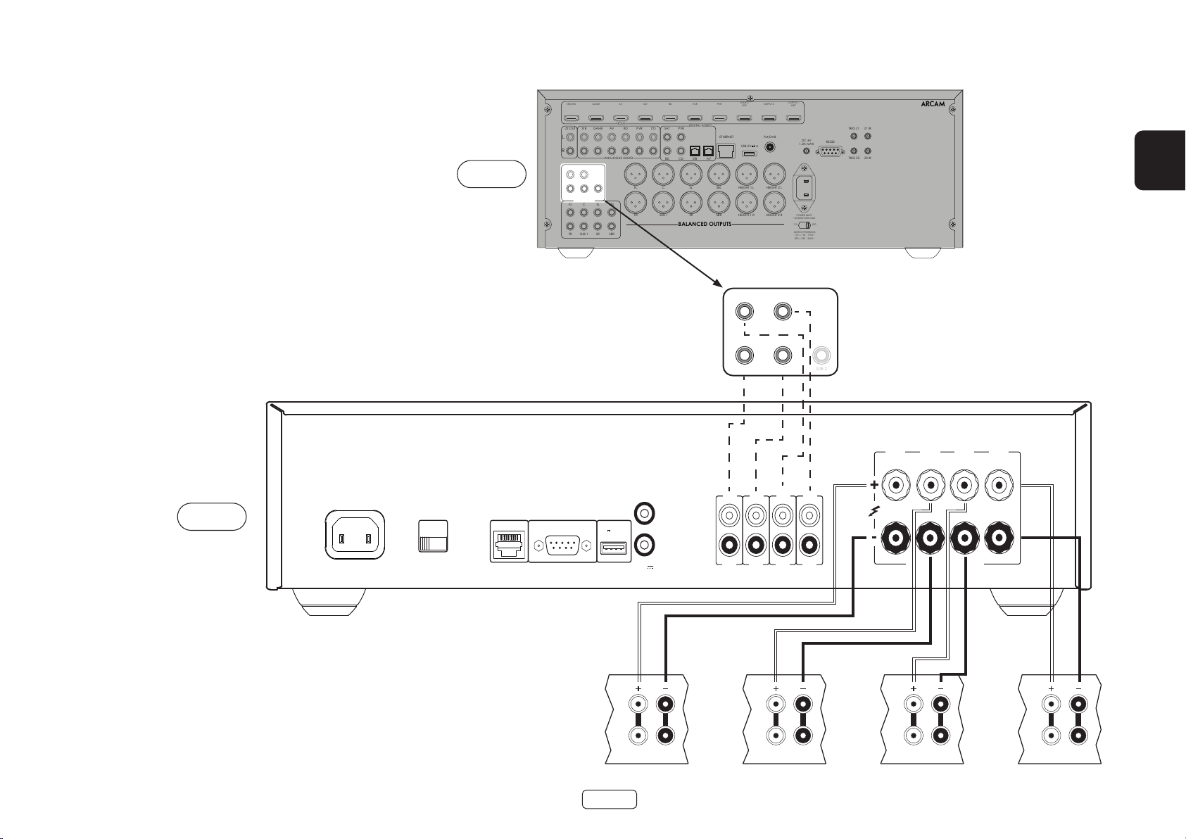
PA410
POWER INLET
110-120V/220-240V ~ 50/60Hz
500W MAX
SUPPLY
VOLTAGE
SWITCH POSITIONS
115 = 110 - 120V ~
230 = 220 - 240V ~
RS232NET USB
5V 100mA
CH1
4-16 OHMS
CLASS 2 WIRING
CH2CH3CH4
IN4
OUT4
IN3
OUT3
IN2
OUT2
IN1
OUT1
TRIGGER OUT
(12V 100mA)
TRIGGER IN
SUB 2
Connectez la borne de haut-parleur positive ROUGE
identifiée CH1 àCH4+ à la borne positive de votre hautparleur. De même, connectez la borne de haut-parleur
négative NOIRE du même canal à la borne négative de
votre haut-parleur.
AV860
STB/MHL
STB
Z2 OUT
L
R
HEIGHT1 HEIGHT2
L
R
PREAMP OUT
FL C SL SBL
FR SUB 1 SR SBR
GAME
GAME
SUB 2
AV
HDMI
AV
ANALOGUE AUDIO
BD
BD
SAT
PVR
FL C SL SBL HEIGHT 1 L HEIGHT 2 L
FR SUB 1 SR SBR HEIGHT 1 R HEIGHT 2 R
CD
BD CD
VCR
DIGITAL AUDIO
PVRSAT
STB AV
BALANCED OUTPUTS
ZONE 2
PVR
OUT
ETHERNET
USB 5V
OUTPUT 1
OUTPUT 2
ARC
FM/DAB
DC 6V
1A
1.2A MAX
TRIG Z1 Z1 IR
RS232
TRIG Z2 Z2 IR
23425
FR
POWER INLET
~50/60Hz 50W MAX
115 230
SWITCH POSITIONS
115 = 110 - 115V~
230 = 220 - 240V~
Répétez ce processus pour les autres enceintes, en
utilisant les mêmes bornes respectives de haut-parleur
sur l’amplificateur et d’entrée sur vos haut-parleurs pour
chaque canal.
NOTE: Tous les canaux sont identiques, il n’est donc
pas nécessaire de connecter des canaux de sortie AVR
spécifiques à des canaux d’amplificateur spécifiques.
PA410
HEIGHT 1 HEIGHT 2
L
R
PREAMP OUT
HF
LF
Hauteur1 Droit Hauteur1 Gauche
FR-13
HF
LF
Hauteur2 Droit Hauteur2 Gauche
HF
LF
HF
LF
Page 38

Mode ponté mono – PA240 seu-
RCA
XLR
INPUT
+
4-16 OHMS. CLASS 2 WIRING
+
- -
R
ST BRIDGE DM
GAIN
25dB 31dB
MODE
L
INR INL
INR
OUTR
INL
OUTL
RCA
XLR
INPUT
+
4-16 OHMS. CLASS 2 WIRING
+
- -
R
ST BRIDGE DM
GAIN
25dB 31dB
MODE
L
INR INL
INR
OUTR
INL
OUTL
PREAMP OUT
CSLSBL
SUB 1SRSBR
lement
Le mode mono ponté nécessite l’utilisation d’un PA240
pour chaque canal.
Note: En mode ponté, seules les sorties de haut-parleur
L+ et R+ sont nécessaires.
AVERTISSEMENT: N’eec tuez aucun branchement sur
les bornes de haut-parleur L- ou R- de l’amplicateur,
vous risqueriez de l’endommager gravement.
Note: L’appareil doit être connecté en utilisant
RCA ou XLR. Les deux versions ne sont
présentées qu’à titre d’exemple.
Haut-parleur
droit
HF
Sur l’un des PA240, branchez la borne de haut-parleur
positive ROUGE identifiée L+ à la borne positive de
votre haut-parleur de gauche.
Connectez la borne de haut-parleur positive ROUGE
identifiée R+ à la borne négative de votre haut-parleur
de gauche.
Répétez ce processus pour le haut-parleur droit, en
utilisant les MÊMES bornes sur l’autre PA240.
FL
FR
FL
FR
Note : L+ doit être connecté à la borne positive de
l’enceinte et R+ à la borne négative de l’enceinte des
DEUX enceintes, sinon les enceintes seront déphasées.
AVERTISSEMENT: Assurez-vous SANS AUCUN DOUTE
que vous avez utilisé les bornes L+ et R+ de l’appareil
PA240. Les bornes L- et R- ne sont PAS nécessaires
dans cet arrangement.
STB/MHL
STB
Z2 OUT
L
R
HEIGHT1 HEIGHT2
L
R
PREAMP OUT
FL C SL SBL
FR SUB 1 SR SBR
GAME
GAME
SUB 2
AV
HDMI
AV
ANALOGUE AUDIO
BD
BD
SAT
DIGITAL AUDIO
CD
PVR
PVRSAT
BD CD
FL C SL SBL HEIGHT 1 L HEIGHT 2 L
FR SUB 1 SR SBR HEIGHT 1 R HEIGHT 2 R
BALANCED OUTPUTS
AV860
Dans cette configuration, une seule interconnexion
est nécessaire pour chaque amplificateur de puissance
et elle doit être connectée à l’entrée. IN L . Les
interconnexions peuvent être XLR (recommandées
pour des longueurs de câble plus longues) ou phono
(RCA). Réglez les commutateurs INPUT des deux PA240
aux positions appropriées pour les câbles utilisés.
Note: L’entrée IN R n’a aucun rôle dans cet arrangement.
VCR
STB AV
PVR
ETHERNET
ZONE 2
OUT
USB 5V
OUTPUT 1
OUTPUT 2
ARC
FM/DAB
DC 6V
1A
1.2A MAX
POWER INLET
~50/60Hz 50W MAX
115 230
SWITCH POSITIONS
115 = 110 - 115V~
230 = 220 - 240V~
TRIG Z1 Z1 IR
RS232
TRIG Z2 Z2 IR
Note:
Assurez-vous que le commutateur
25dB 31dB
RCA ou XLR.
INPUT est réglé sur le type d’entrée
GAIN
Il est recommandé de régler le
commutateur GAIN sur 25 dB
INPUT
XLR
RCA
Assurez-vous que le commutateur
MODE est en mode ponté, BRIDGE
Haut-parleur de gauche
MODE
ST BRIDGE DM
HF
23425
LF
LF
PA240
PA240
FR-14
Page 39
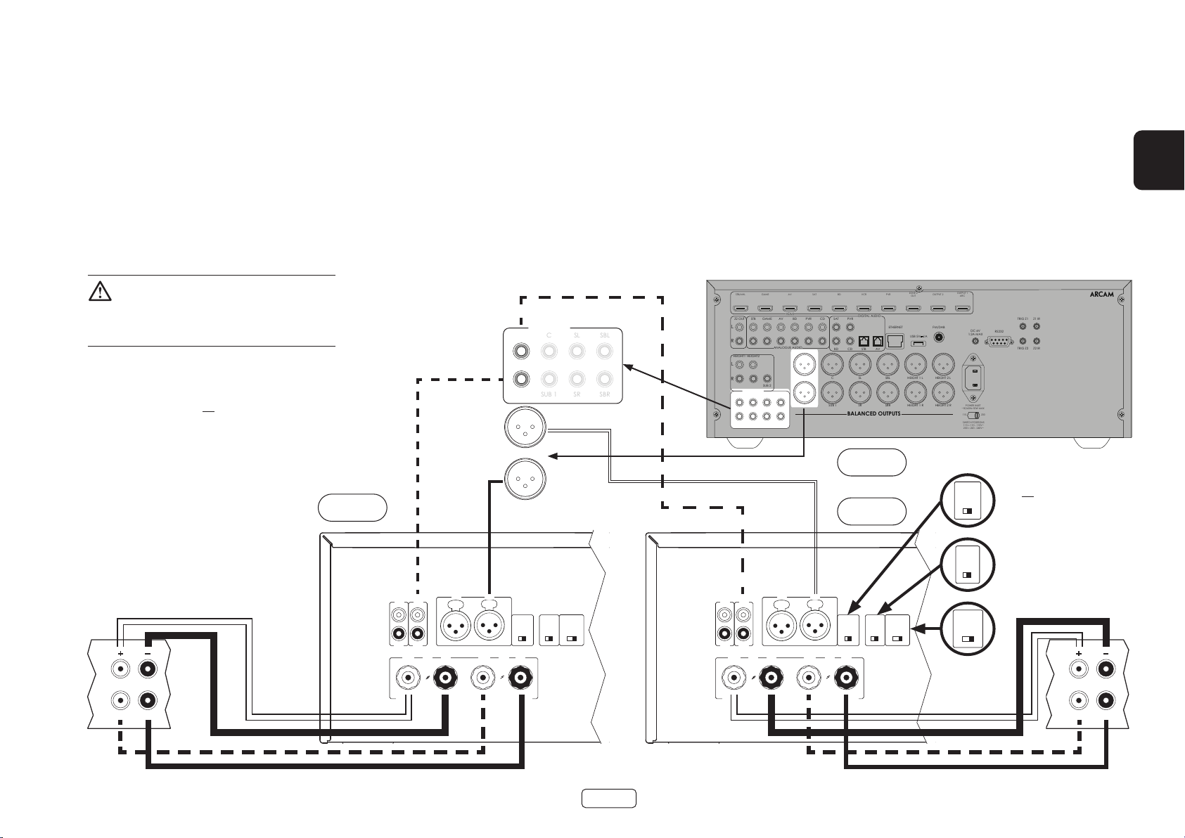
Mono double/Mode Bi Amp – PA240 seulement
RCA
XLR
INPUT
+ +
- -
R
ST BRIDGE DM
GAIN
25dB 31dB
MODE
L
INR INL
INR
OUTR
INL
OUTL
RCA
XLR
INPUT
+ +
- -
R
ST BRIDGE DM
GAIN
25dB 31dB
MODE
L
INR INL
INR
OUTR
INL
OUTL
PREAMP OUT
CSLSBL
SUB 1SRSBR
Le mono double requiert l’utilisation d’un PA240 pour
chaque canal.
Sur l’un des PA240, connectez la borne de haut-parleur
positive ROUGE identifiée L+ à la borne LF positive du
haut-parleur gauche. De la même manière, branchez la
borne de haut-parleur négative NOIRE identifiée L - à la
borne négative LF de votre haut-parleur gauche.
AVERTISSEMENT : Les haut-parleurs qui
prennent en charge la biamplication ont une
bande métallique qui relie les bornes basse
fréquence (LF) et haute fréquence (HF). Celle-ci DOIT
être supprimée dans un système biamplié.
Note: L’appareil doit être connecté en utilisant
RCA ou XLR. Les deux versions ne sont
présentées qu’à titre d’exemple.
Haut-parleur
droit
À l’aide d’un deuxième câble d’enceinte, connectez la
borne de haut-parleur positive ROUGE identifiée R+ à la
borne positive HF de votre haut-parleur de gauche. De
la même manière, connectez la borne de haut-parleur
négative NOIRE identifiée R- à la borne négative HF de
votre haut-parleur.
Répétez ce processus pour le haut-parleur droit, en
utilisant les mêmes bornes sur l’autre PA240.
FL
FR
FL
PA240
FR
Dans cette configuration, une seule interconnexion
est nécessaire pour chaque amplificateur de puissance
et elle doit être connectée à l’entrée. IN L . Les
interconnexions peuvent être XLR (recommandées
pour des longueurs de câble plus longues) ou phono
(RCA). Réglez les commutateurs INPUT des deux PA240
aux positions appropriées pour les câbles utilisés.
Note: L’entrée IN R n’a aucun rôle dans cet arrangement.
STB/MHL
STB
Z2 OUT
L
R
HEIGHT1 HEIGHT2
L
R
PREAMP OUT
FL C SL SBL
FR SUB 1 SR SBR
GAME
GAME
SUB 2
AV
HDMI
AV
ANALOGUE AUDIO
BD
BD
SAT
PVR
FL C SL SBL HEIGHT 1 L HEIGHT 2 L
FR SUB 1 SR SBR HEIGHT 1 R HEIGHT 2 R
CD
VCR
DIGITAL AUDIO
PVRSAT
BD CD
STB AV
BALANCED OUTPUTS
AV860
PA240
FR
ZONE 2
PVR
OUT
ETHERNET
USB 5V
OUTPUT 1
OUTPUT 2
ARC
FM/DAB
DC 6V
1A
1.2A MAX
POWER INLET
~50/60Hz 50W MAX
115 230
SWITCH POSITIONS
115 = 110 - 115V~
230 = 220 - 240V~
TRIG Z1 Z1 IR
RS232
TRIG Z2 Z2 IR
23425
Note:
Assurez-vous que le commutateur
INPUT est réglé sur le type d’entrée
GAIN
25dB 31dB
RCA ou XLR.
Assurez-vous que le commutateur
GAIN est réglé sur 31dB.
Assurez-vous que le commutateur
INPUT
MODE est réglé sur le mode dual
XLR
RCA
mono, DM
Haut-parleur
MODE
ST BRIDGE DM
de gauche
HF
LF
HF
LF
FR-15
Page 40

Dépannage
Problème Vérifiez les points suivants
Pas de son L’amplificateur PA720 / PA240 / PA410 est correctement branché et
mis sous tension.
Votre source audio/vidéo (par exemple préamplificateur) est
correctement connectée.
Le PA720 / PA240 / PA410 n’est pas en mode protection, comme décrit
dans la section suivante.
La sortie sonore du PA720, PA240 and PA410 n’est pas désactivée.
Le son coupe de façon inattendue Le PA720 / PA240 / PA410 peut entrer en mode de protection, selon
le défaut détecté. Le voyant DEL du panneau avant indique le type de
défaut, selon la liste ci-dessous.
CLIGNOTEMENT RAPIDE EN BLANC : La température interne de l’appareil
a atteint un niveau dangereux. Laissez le PA720 / PA240 / PA410 revenir
à sa température normale.
CLIGNOTEMENT RAPIDE ROUGE : L’amplificateur PA720 / PA240 / PA410
a détecté un court-circuit du haut-parleur. Si cela se produit, veuillez
inspecter tous les câbles d’enceintes pour vous assurer qu’aucun
d’entre eux n’est court-circuité ensemble. Ce défaut est très fréquent
lorsque des fils dénudés sont utilisés pour réaliser les connexions des
enceintes.
CLIGNOTEMENT RAPIDE ORANGE : PA720 et PA240 seulement.
L’amplificateur a détecté un décalage en courant continu.
Si l’un des défauts décrits ci-dessus se produit, l’amplificateur s’éteint de
lui-même et l’alimentation des enceintes est coupée. Pour continuer à
utiliser l’appareil PA720 / PA240 / PA410, la défectuosité doit être éliminée
et l’appareil doit être éteint puis remis sous tension.
FR-16
Page 41

Caractéristiques techniques
PA720
Puissance de sortie continue @ 0.2% THD, par canal
Sept canaux avec charge 4 Ω/8 Ω, 1 kHz 140W / 100W
Cinq canaux avec charge 4 Ω/8 Ω, 1 kHz 175W / 110W
Deux canaux avec charge 4 Ω/8 Ω, 1 kHz 225W / 140W
Distorsion harmonique, 80 % de puissance,
8 Ω à 1 kHz
Entrées
Sensibilité d’entrée 100 W/8 Ω 800mV RMS 1.6V RMS
Rapport signal/bruit (A-wtd) 100 W/8 Ω 112dB
Impédance d’entrée 10kΩ
Réponse en fréquence 20 - 20kHz +/-0.05dB
Général
Tension de secteur 110–120V or 220–240V, 50–60Hz
Consommation d’énergie maximale 1.5kW
Faible consommation en veille 0.5W
Consommation en veille réseau 2W
Dimensions l x H x P (y compris les
pieds, le bouton de commande et
les bornes du haut-parleur)
Poids (net) 18kg
Poids (brut) 19.7kg
0,002 %
Type RCA Type XLR
433 x 425 x 177mm
FR
Toutes les valeurs de spécication sont typiques,
sauf indication contraire. Arcam a une politique
d’amélioration continue de ses produits. Cela
signie que les conceptions et les spécications sont
modiables sans préavis. Sauf erreur ou omission
FR-17
Page 42

PA240
Puissance de sortie continue @ 0.2% THD, par canal
Deux canaux avec charge 4Ω/8 Ω, 1 kHz 380W / 225W
Un canal avec charge 8 Ω mode ponté, 1 kHz 790W
Distorsion harmonique, 80 %
de puissance, 8 Ω à 1 kHz
Entrées
Sensibilité d’entrée 200 W/8 Ω 1.15V RMS 2.3V RMS 2.3V RMS 4.6V RMS
Rapport signal/bruit (A-wtd) 100 W/8 Ω 110dB 114dB 110dB 114dB
Impédance d’entrée 10kΩ
Réponse en fréquence 20 - 20kHz +/-0.05dB
Général
Tension de secteur 110–120V or 220–240V, 50–60Hz
Consommation d’énergie maximale 1.5kW
Faible consommation en veille 0.5W
Consommation en veille réseau 2W
Dimensions l x H x P (y compris les
pieds, le bouton de commande et
les bornes du haut-parleur)
Poids (net) 18kg
Poids (brut) 19.7kg
0,001 %
Type RCA Type XLR
31dB 25dB 31dB 25dB
433 x 425 x 177mm
Toutes les valeurs de spécication sont typiques,
sauf indication contraire. Arcam a une politique
d’amélioration continue de ses produits. Cela
signie que les conceptions et les spécications sont
modiables sans préavis. Sauf erreur ou omission
FR-18
Page 43

PA410
Puissance de sortie continue @ 0.2% THD, par canal
Quatre canaux avec charge4 Ω/8 Ω, 1 kHz 70W / 50W
Deux canaux avec charge4 Ω/8 Ω, 1 kHz 90W / 60W
Distorsion harmonique, 80 %
de puissance, 8 Ω à 1 kHz
Entrées
Sensibilité d’entrée 50 W/8 Ω 560mV RMS
Rapport signal/bruit (A-wtd) 50 W/8 Ω 106dB
Impédance d’entrée 10kΩ
Réponse en fréquence 20 - 20kHz +/-0.2dB
Général
Tension de secteur 110–120V or 220–240V, 50–60Hz
Consommation d’énergie maximale 700W
Faible consommation en veille 0.5W
Consommation en veille réseau 2W
Dimensions l x H x P (y compris les
pieds, le bouton de commande et
les bornes du haut-parleur)
Poids (net) 10kg
Poids (brut) 11.5kg
0,003 %
433x325x105mm
FR
Toutes les valeurs de spécication sont typiques,
sauf indication contraire. Arcam a une politique
d’amélioration continue de ses produits. Cela
signie que les conceptions et les spécications sont
modiables sans préavis. Sauf erreur ou omission
FR-19
Page 44

Garantie Internationale
Vous avez ainsi le droit de faire réparer l’appareil gratuitement au cours des cinq premières années suivant son achat,
à condition qu’il ait été acheté à l’origine chez un revendeur agréé Arcam. Le revendeur Arcam est responsable de
tout le service après-vente. Le fabricant décline toute responsabilité pour les défauts résultant d’un accident, d’une
mauvaise utilisation, d’un abus, de l’usure, d’une négligence ou d’un réglage et/ou d’une réparation non autorisés,
ainsi que pour les dommages ou pertes survenant pendant le transport à destination ou en provenance de la
personne qui fait valoir la garantie.
La garantie comprend:
Les pièces (à l’exclusion des lecteurs de disques) et les coûts de main-d’œuvre pendant cinq ans à compter de la
date d’achat (voir les conditions générales supplémentaires ci-dessous). Au bout de cinq ans, vous devez payer les
pièces et la main-d’œuvre.
Les lecteurs de disque (de tout type) sont couverts par cette garantie pendant deux ans à compter de la date d’achat.
La garantie ne couvre pas le remplacement de la pile en aucun temps.
La garantie ne couvre en aucun moment les frais de transport.
Réclamations sous garantie
Cet équipement doit être emballé dans son emballage d’origine et retourné au revendeur auprès duquel il a
été acheté. Il doit être retourné préaffranchi par un service de courrier reconnu – et non par la poste. Aucune
responsabilité ne peut être acceptée pour l’appareil pendant le transport vers le revendeur ou le distributeur et il est
donc conseillé aux clients d’assurer l’appareil contre toute perte ou tout dommage pendant le transport.
Pour plus d’informations, contactez Arcam au arcam.support@harman.co.uk.
Des problèmes ?
Si votre revendeur Arcam n’est pas en mesure de répondre à toute question concernant ce produit ou tout autre produit
Arcam, veuillez contacter le service clientèle Arcam à l’adresse ci-dessus et nous ferons de notre mieux pour vous aider.
Enregistrement en ligne
Vous pouvez enregistrer votre produit en ligne au www.arcam.co.uk.
FR-20
Page 45

LEISTUNGSVERSTÄRKER
HANDBUCH
DE
PA720 / PA240 / PA410
Page 46

Willkommen
Vielen Dank und herzlichen Glückwunsch...
...zum Kauf Ihres Leistungsverstärkers des Typs PA720, PA240 or PA410 von Arcam.
Arcam fertigt bereits seit über vier Jahrzehnten professionelle Audio-Produkte von höchster Qualität. Bei den
neuen PA720, PA240 and PA410 Leistungsverstärkern handelt es sich um die modernsten einer langen Serie
preisgekrönter Hi-Fi-Geräte. Das Design der HDA-Produktreihe beruht auf der langjährigen Erfahrung von Arcam,
eines der angesehensten britischen Unternehmen in der Audiotechnologiebranche und Hersteller der bislang
leistungsfähigsten Mehrkanal-Leistungsverstärker, die so konzipiert und gebaut wurden, dass Sie Ihnen jahrelang
einen einzigartigen Hörgenuss bieten.
Dieses Handbuch ist eine Anleitung zur Aufstellung und Inbetriebnahme der PA720, PA240 and PA410 und enthält
Informationen zu sämtlichen der erweiterten Funktionen. Das Inhaltsverzeichnis auf dieser Seite zeigt Ihnen, welche
Abschnitte von besonderem Interesse für Sie sind.
Wir hoffen, dass Ihnen Ihr Produkt viele Jahre lang Freude bereiten wird. Im unwahrscheinlichen Fall eines
Produktfehlers bzw. wenn Sie Interesse an zusätzlichen Informationen über Arcam Produkte haben, steht Ihnen
unser Händlernetz gerne zur Verfügung. Weitere Informationen finden Sie auch auf der Website von Arcam unter
www.arcam.co.uk.
Ihr PA720, PA240 and PA410-Entwicklungsteam
DE-2
Page 47

Inhalt
Willkommen DE-2
Übersicht DE-4
Gerät aufstellen DE-4
Verbindungskabel DE-4
Netzanschluss DE-4
Anschlüsse und Bedienelemente auf der Rückseite PA720 DE-5
Anschlüsse und Bedienelemente auf der Rückseite PA240 DE-6
Anschlüsse und Bedienelemente auf der Rückseite PA410 DE-7
Anschlüsse zur Steuerung des Systems DE-8
Netzwerk und RS232 DE-8
USB DE-8
Trigger EIN-/AUSGANG DE-8
Anschlüsse und Bedienelemente auf der Frontblende DE-9
Inbetriebnahme DE-10
Einschalten DE-10
Automatischer Standby-Modus DE-10
Netzwerk und RS322 im Standby-Modus DE-10
Stummschalten der Lautsprecherausgänge DE-10
Betriebsartumschalter DE-10
Anschließen der Audioquellen und Lautsprecher DE-11
Brückenbetrieb - nur bei PA240 DE-14
Dual Mono- / Bi Amp-Betrieb - nur bei PA240 DE-15
Störungserkennung DE-16
Technische Daten DE-17
PA720 DE-17
PA240 DE-18
PA410 DE-19
Weltweite Garantie DE-20
DE
DE-3
Page 48

Übersicht
Die PA720, PA240 and PA410
Verstärker von Arcam
Die PA720, PA240 and PA410 Leistungsverstärker von
Arcam bieten erstklassige Klangqualität für die optimale
Wiedergabe Ihrer Musik.
Zusätzlich zu der langjährigen Erfahrung in der
Entwicklung von Verstärkern verwendet Arcam die
hochwertigsten Komponenten und besten technischen
Verfahren für seine Produkte, um Verstärker zu fertigen,
die Ihnen jahrelangen Musikgenuss und zuverlässigen
Service bieten.
Dank eines Netzteils mit Ringkerntransformator, einem
akustisch gedämpften, resonanzarmen Gehäuse,
Klasse-G-Technologie (PA240 und PA720), parallelen
Transistor-Endstufen (PA240) sowie außerordentlich
selten auftretenden Störungen durch Verzerrung und
Rauschen sind die PA720, PA240 and PA410 Verstärker
in der Lage, Musik in Studioqualität und mit maximaler
Detailtreue wiederzugeben. Seien Sie sich gewiss,
die Musik genauso zu hören, wie es der Künstler
beabsichtigt.
Die PA720, PA240 and PA410 Verstärker sind so
konzipiert, dass sie ein Leistungsniveau erzeugen, mit
dem Ihre Musik wahrlich zum Leben erweckt wird.
Gerät aufstellen
Stellen Sie den Verstärker auf einer ebenen, festen
Oberfläche auf. Achten Sie darauf, dass das Gerät
keinem direkten Sonnenlicht oder Wärme- bzw.
Feuchtigkeitsquellen ausgesetzt ist.
Stellen Sie den PA720, PA240 or PA410 nicht auf einen
Leistungsverstärker oder eine andere Wärmequelle.
Stellen Sie den Verstärker nicht in ein geschlossenes
Bücherregal oder einen Schrank, es sei denn, es ist
für ausreichende Belüftung gesorgt. Die Verstärker
PA720, PA240 and PA410 laufen im Normalbetrieb
konstruktionsbedingt etwas warm.
Stellen Sie kein anderes Gerät oder einen Gegenstand
auf den Verstärker, da dies die Luftzirkulation
um den Kühlkörper behindern kann, und der
Verstärker dadurch überhitzt. (Ein auf dem Verstärker
abgestelltes Gerät würde ebenfalls überhitzen.)
PA720
Stellen Sie keinen Plattenspieler auf dieses Gerät.
Plattenspieler reagieren sehr empfindlich auf
das von Netzteilen erzeugte Rauschen, das als
Hintergrundbrummen zu hören ist, wenn sich der
Plattenspieler zu dicht am Gerät befindet.
Die normale Funktion des Geräts kann durch starke
elektromagnetische Interferenzen gestört werden.
Setzen Sie in diesem Fall einfach das Gerät mit der
Ein-/Austaste zurück oder stellen Sie es an einen
anderen Standort auf.
Verbindungskabel
Wir empfehlen den Einsatz hochwertiger abgeschirmter
Kabel, die für diese spezielle Anwendung entwickelt
wurden. Andere Kabel verfügen über andere
Impedanzen, die die Leistung Ihres Systems verringern
(verwenden Sie z.B. keine für Video vorgesehenen Kabel
zur Übertragung von Audiosignalen). Alle Kabel sollten
so kurz wie möglich gehalten werden.
Bei der Verkabelung der Geräte sollten Sie darauf
achten, dass das Netzkabel so weit wie möglich von
den Audiokabeln entfernt ist. Andernfalls kann es
zu unerwünschtem Rauschen in den Audiosignalen
kommen.
POWER AMPLIFIER
POWER
STANDBYMUTE
Netzanschluss
Der Verstärker wird mit einem Netzkabel mit
vergossenem Netzstecker geliefert. Überprüfen Sie, dass
das mitgelieferte Kabel mit Ihrem Anschluss kompatibel
ist – falls Sie ein neues Netzkabel benötigen, wenden
Sie sich bitte an Ihren Arcam-Händler.
Falls Ihre Netzanschlussspannung oder das Netzkabel
nicht übereinstimmen, wenden Sie sich sofort an Ihren
Arcam-Händler.
Stecken Sie den IEC-Stecker des Netzkabels in die
Netzbuchse auf der Rückseite des Verstärkers, so dass
dieser fest sitzt. Stecken Sie den Stecker des anderen
Kabelendes in eine Steckdose und schalten Sie diese
ein.
DE-4
Page 49

Anschlüsse und Bedienelemente auf der Rückseite PA720
SYMMETRISCHE XLR-AUDIOEINGÄNGE
Schließen Sie hier die XLR-Ausgänge Ihres
Vorverstärkers an.
Siehe „Anschließen der Audioquellen und
Lautsprecher“ auf Seite DE-11.
EINGANGSSCHALTER
Hiermit kann der PA720 für
zwei verschiedene Arten von
Eingangssignalen konfiguriert werden.
Siehe „Anschließen der Audioquellen
und Lautsprecher“ auf Seite DE-11.
Der USB-Anschluss ist nur für
USB
Aktualisierungen der Software
vorgesehen. Siehe „USB“ auf
Seite DE-8.
Mit Trigger IN lässt sich der PA720 über ein externes Audiogerät ein- und ausschalten.
TRIGGER IN / OUT
Mit Trigger OUT ist der PA720 in der Lage, den Betriebszustand anderer angeschlossener
Audiogeräte zu steuern.
Siehe „Trigger EIN-/AUSGANG“ auf Seite DE-8.
DE
IN7
IN6
IN5
IN4
OUT7
OUT6
OUT5
OUT4
EINGÄNGE DES VORVERSTÄRKERS
Schließen Sie hier die Phono-Ausgänge
Ihres Vorverstärkers an.
Siehe „Anschließen der Audioquellen
und Lautsprecher“ auf Seite DE-11.
VORVERSTÄRKERAUSGANG
Die Ausgänge OUT1-OUT7 stellen eine
Kopie ausschließlich des Signals bereit,
das an den Phono-Buchsen IN1-IN7, nicht
jedoch an den XLR-Eingängen, anliegt.
Hinweis: Hierbei handelt es sich um
einen passiven Ausgang. Das bedeutet,
es wird keine zusätzliche Filterung
oder Verstärkung angewendet.
IN3
IN2
IN1
OUT3
OUT2
OUT1
LAUTSPRECHERKLEMMEN
Siehe „Anschließen
der Audioquellen und
Lautsprecher“ auf Seite DE-11.
IN7 IN6 IN5 IN4 IN3 IN2 IN1
CH5CH6CH7
CH4 CH3 CH2 CH1
4-16 OHMSCLASS 2 WIRING
RS232
Mit diesem Anschluss ist die
Fernsteuerung mittels eines
Hausautomationssystems
von einem Drittanbieter oder
Mit diesem Anschluss ist die Fernsteuerung
NETZWERK
mittels eines Hausautomationssystems von
einem Drittanbieter oder Computer möglich.
Siehe „Netzwerk und RS232“ auf Seite DE-8.
Computer möglich.
Siehe „Netzwerk und RS232“ auf
Seite DE-8.
DE-5
RCA
INPUT
XLR
RS232 NET
POWER INLET
110-120V/220-240V~
50/60Hz 1.5kW MAX
NETZEINGANG
Schließen Sie hier das entsprechende
Netzkabel an.
Lesen Sie sich vor Inbetriebnahme Ihres
Verstärkers die Abschnitte „Gerät aufstellen“,
„Netzanschluss“ und „Verbindungskabel“ die
auf Seite DE-4 Seite PA720 durch!
TRIGGER IN
USB
5V
100mA
TRIGGER OUT
(12V 100mA)
SUPPLY
VOLTAGE
SWITCH POSITIONS
115 = 110 - 120V ~
230 = 220 - 240V ~
SPANNUNGSAUSWAHL
Vergewissern Sie sich,
dass die gewählte
Spannung mit der örtlichen
Spannungsversorgung
übereinstimmt.
Page 50

Anschlüsse und Bedienelemente auf der Rückseite PA240
RS232 NET
TRIGGER OUT
(12V 100mA)
TRIGGER IN
POWER INLET
110-120V/220-240V~
50/60Hz 1.5kW MAX
USB
5V
100mA
SWITCH POSITIONS
115 = 110 - 120V ~
230 = 220 - 240V ~
SUPPLY
VOLTAGE
RCA
XLR
INPUT
+
4-16 OHMS. CLASS 2 WIRING
+
- -
R
ST BRIDGE DM
GAIN
25dB 31dB
MODE
L
INR INL
INR
OUTR
INL
OUTL
SYMMETRISCHE XLR-AUDIOEINGÄNGE
Schließen Sie hier die XLR-Ausgänge Ihres
Vorverstärkers an.
Siehe „Anschließen der Audioquellen und
Lautsprecher“ auf Seite DE-11.
EINGANGSSCHALTER
Hiermit lässt sich der PA240 in
unterschiedliche Betriebsmodi versetzen.
Siehe „Anschließen der Audioquellen und
Lautsprecher“ auf Seite DE-11.
Der USB-Anschluss ist nur
USB
für Aktualisierungen der
Software vorgesehen. Siehe
„USB“ auf Seite DE-8.
Mit Trigger IN lässt sich der PA240 über ein externes Audiogerät ein- und ausschalten.
TRIGGER IN / OUT
Mit Trigger OUT ist der PA240 in der Lage, den Betriebszustand anderer
angeschlossener Audiogeräte zu steuern.
Siehe „Trigger EIN-/AUSGANG“ auf Seite DE-8.
EINGÄNGE DES VORVERSTÄRKERS
LAUTSPRECHERKLEMMEN
Schließen Sie hier die Phono-Ausgänge
Ihres Vorverstärkers an.
Siehe „Anschließen der Audioquellen
und Lautsprecher“ auf Seite DE-11.
Lautsprecher“ auf Seite DE-11.
VORVERSTÄRKERAUSGANG
Die Ausgänge OUTL und OUTR stellen eine
Kopie ausschließlich des Signals bereit, das
an den Phono-Buchsen IN L und IN R, nicht
jedoch an den XLR-Eingängen, anliegt.
Hinweis: Hierbei handelt es sich um
einen passiven Ausgang. Das bedeutet,
es wird keine zusätzliche Filterung
oder Verstärkung angewendet.
Siehe „Anschließen
der Audioquellen und
RS232
Mit diesem Anschluss ist die
Fernsteuerung mittels eines
Hausautomationssystems von einem
Drittanbieter oder Computer möglich.
Siehe „Netzwerk und RS232“ auf Seite
DE-8.
NETZWERK
Mit diesem Anschluss ist die Fernsteuerung
mittels eines Hausautomationssystems von
einem Drittanbieter oder Computer möglich.
Siehe „Netzwerk und RS232“ auf Seite DE-8.
DE-6
Schließen Sie hier das entsprechende
NETZEINGANG
Netzkabel an.
Lesen Sie sich vor Inbetriebnahme Ihres
Verstärkers die Abschnitte „Gerät aufstellen“,
„Netzanschluss“ und „Verbindungskabel“ die
auf Seite DE-4 Seite PA240 durch!
SPANNUNGSAUSWAHL
Vergewissern Sie sich,
dass die gewählte
Spannung mit der örtlichen
Spannungsversorgung
übereinstimmt.
Page 51

POWER INLET
110-120V/220-240V ~ 50/60Hz
500W MAX
SUPPLY
VOLTAGE
SWITCH POSITIONS
115 = 110 - 120V ~
230 = 220 - 240V ~
RS232NET USB
5V 100mA
CH1
4-16 OHMS
CLASS 2 WIRING
CH2CH3CH4
IN4
OUT4
IN3
OUT3
IN2
OUT2
IN1
OUT1
TRIGGER OUT
(12V 100mA)
TRIGGER IN
Anschlüsse und Bedienelemente auf der Rückseite PA410
entsprechende Netzkabel an.
Spannung mit der örtlichen
NETZEINGANG
Schließen Sie hier das
SPANNUNGSAUSWAHL
Vergewissern Sie sich,
dass die gewählte
Spannungsversorgung
übereinstimmt.
Verbinden Sie über diesen Anschluss Ihr
kabelgebundenes lokales Netzwerk. Über den
anderen Anschluss können Sie eine Verbindung
zu weiteren Geräten herstellen.
Siehe „Netzwerk und RS232“ auf Seite DE-8.
Mit diesem Anschluss ist die
RS232
Fernsteuerung mittels eines
Hausautomationssystems
von einem Drittanbieter oder
Computer möglich.
Siehe „Netzwerk und RS232“
auf Seite DE-8.
NETZWERK
Der USB-Anschluss ist nur für
USB
Aktualisierungen der Software
vorgesehen. Siehe „USB“ auf
Seite DE-8.
EINGÄNGE DES VORVERSTÄRKERS
Schließen Sie hier die Phono-Ausgänge
Ihres Vorverstärkers an.
Siehe „Anschließen der Audioquellen
und Lautsprecher“ auf Seite DE-11.
VORVERSTÄRKERAUSGANG
Die Ausgänge OUT1 bis OUT4 stellen
eine Kopie des an den Phono-Buchsen
IN1 bis IN4 anliegenden Signals bereit.
Hinweis: Hierbei handelt es sich um
einen passiven Ausgang. Das bedeutet,
es wird keine zusätzliche Filterung
oder Verstärkung angewendet.
DE-7
Mit Trigger IN lässt sich der PA410 über ein externes Audiogerät ein- und ausschalten.
TRIGGER IN / OUT
Mit Trigger OUT ist der PA410 in der Lage, den Betriebszustand anderer
angeschlossener Audiogeräte zu steuern.
Siehe „Trigger EIN-/AUSGANG“ auf Seite DE-8.
LAUTSPRECHERKLEMMEN
Siehe „Anschließen
der Audioquellen und
Lautsprecher“ auf Seite DE-11.
Lesen Sie sich vor Inbetriebnahme Ihres
Verstärkers die Abschnitte „Gerät aufstellen“,
„Netzanschluss“ und „Verbindungskabel“ die
auf Seite DE-4 Seite PA410 durch!
DE
Page 52

RS232 NET
TRIGGER OUT
(12V 100mA)
TRIGGER IN
POWER INLET
110-120V/220-240V~
50/60Hz 1.5kW MAX
USB
5V
100mA
SWITCH POSITIONS
115 = 110 - 120V ~
230 = 220 - 240V ~
SUPPLY
VOLTAGE
RCA
XLR
INPUT
IN7
OUT7
IN6
OUT6
IN5
OUT5
IN4
OUT4
IN3
OUT3
IN2
OUT2
IN1
OUT1
IN7 IN6 IN5 IN4 IN3 IN2 IN1
CH4 CH3 CH2 CH1
4-16 OHMSCLASS 2 WIRING
CH5CH6CH7
Anschlüsse zur Steuerung
des Systems
Netzwerk und RS232
Die Verstärker PA720, PA240 and PA410 verfügen jeweils
über einen Netzwerk- und einen RS232-Anschluss, über
den sich eine Verbindung zu einem lokalen Netzwerk,
Computer oder Heimautomatisierungssystem herstellen
lässt. So kann der Verstärker auch aus der Ferne gesteuert
und überwacht werden.
Hierzu stehen Ihnen zahlreiche Systeme von Drittanbietern
zur Verfügung, mit denen Sie all Ihre Unterhaltungsgeräte
präzise steuern können. Wenden Sie sich für weitere
Informationen an Ihren Händler oder Installateur.
Technische Einzelheiten und weitere Informationen
zu den Steuerprotokollen finden Sie in der Unterlage
zur Steuerung des PA720 / PA240 / PA410 via RS232/IP,
die jeweils unter www.arcam.co.uk heruntergeladen
werden können.
Hinweis: Die Steuerung über ein Netzwerk und
RS232 wird im Standby-Modus deaktiviert, um den
Stromverbrauch im Bereitschaftszustand zu reduzieren.
Informationen zum Aktivieren der Steuerung über ein
Netzwerk finden Sie im Abschnitt „Netzwerk und RS322
im Standby-Modus“ auf Seite DE-10.
GAME
STB/MHL
STB
GAME
Z2 OUT
L
R
HEIGHT1 HEIGHT2
L
R
SUB 2
PREAMP OUT
FL C SL SBL
FR SUB 1 SR SBR
Netzwerk-Router
AV
HDMI
AV
ANALOGUE AUDIO
BD
BD
SAT
PVR
FL C SL SBL HEIGHT 1 L HEIGHT 2 L
FR SUB 1 SR SBR HEIGHT 1 R HEIGHT 2 R
CD
BD CD
VCR
DIGITAL AUDIO
PVRSAT
STB AV
BALANCED OUTPUTS
1 2 3 4NET
NET
PVR
ETHERNET
ZONE 2
OUT
USB 5V
OUTPUT 1
OUTPUT 2
ARC
FM/DAB
DC 6V
1A
1.2A MAX
POWER INLET
~50/60Hz 50W MAX
115 230
SWITCH POSITIONS
115 = 110 - 115V~
230 = 220 - 240V~
TRIG Z1 Z1 IR
RS232
TRIG Z2 Z2 IR
23425
AV860
Heimautomationssteuerung
RS232
USB
Der USB-Anschluss wird nur für Softwareaktualisierungen
verwendet. Besuchen Sie für die neueste Software
sowie weitere Informationen www.arcam.uk.
Trigger EIN-/AUSGANG
Der Betriebszustand des PA720, PA240 and PA410 kann
problemlos mit einem kompatiblen Audio-/Videogerät
(z. B. einem Arcam AVR) gesteuert werden. Verbinden
Sie dazu mit Hilfe eines Mono-3,5-mm-Klinkenkabels
den Ausgang TRIGGER OUT des Audiogeräts mit dem
Eingang TRIGGER IN des PA720, PA240 or PA410.
Auf ähnliche Weise kann der PA720, PA240 and PA410 auch
den Betriebszustand eines kompatiblen Produkts (z. B.
eines anderen PA720, PA240 or PA410) steuern. Verbinden
Sie dazu mit Hilfe eines Mono-3,5-mm-Klinkenkabels den
Eingang TRIGGER IN des Audiogeräts mit dem sich am
PA720, PA240 or PA410 befindlichen Ausgang TRIGGER OUT.
Hinweis: Die dafür benötigten Kabel sind nicht im
Lieferumfang enthalten.
Heimautomationssteuerung
POWER INLET
110-120V/220-240V ~ 50/60Hz
500W MAX
SUPPLY
VOLTAGE
SWITCH POSITIONS
115 = 110 - 120V ~
230 = 220 - 240V ~
RS232NET USB
5V 100mA
TRIGGER IN
TRIGGER OUT
(12V 100mA)
PA720
IN4
IN3
OUT4
OUT3
DE-8
CH2CH3CH4
CH1
IN2
IN1
OUT2
OUT1
CLASS 2 WIRING
4-16 OHMS
PA410
Page 53

Anschlüsse und Bedienelemente auf der Frontblende
BETRIEBSANZEIGE UND
NETZSCHALTER
Siehe „Einschalten“ auf Seite DE-10.
DE
POWER AMPLIFIER
PA720
Hierüber können Sie die Stummschaltung der
STUMMSCHALTUNG
Lautsprecherausgänge des PA720, PA240 or PA410
aktivieren oder deaktivieren.
Siehe „Stummschalten der Lautsprecherausgänge“
auf Seite DE-10.
DE-9
POWER
STANDBYMUTE
STANDBY-MODUS DES GERÄTS
Siehe „Einschalten“ auf Seite DE-10.
Page 54

Inbetriebnahme
Einschalten
Mit der Taste POWER wird das Gerät ein oder
ausgeschaltet. Die Status-LED zeigt den Status des
Verstärkers an: Sie wechselt von Rot über Orange nach
Weiß, wenn das Gerät mit einer Steckdose verbunden
und es eingeschaltet wurde.
Durch Drücken der STBY-Taste bei eingeschaltetem Gerät
wird der PA720, PA240 or PA410 in den Standby-Modus
versetzt. Drücken Sie die STBY-Taste erneut, um das Gerät
aus dem Standby-Modus heraus wieder in Betrieb zu
nehmen.
Automatischer Standby-Modus
Um den internationalen Bestimmungen für
Verbraucherprodukte zu entsprechen, ist dieses
Gerät so konzipiert, dass es sich, sollte es über einen
längeren Zeitraum keine Interaktion mit dem Benutzer
und kein Signal über einen der Audioeingänge
registrieren, in den Standby-Modus versetzt
(Standard ist 20 Minuten). Das Gerät kann durch
Drücken der sich auf der Vorderseite befindlichen
STBY-Taste, Aktivierung der Eingänge TRIGGER IN oder
RS232 oder mit einem Befehl über Ethernet aus dem
Standby-Modus gebracht werden (sofern aktiviert,
siehe „Netzwerk und RS322 im Standby-Modus“ für
weitere Informationen).
Der Zeitpunkt, an dem sich das Gerät automatisch
in den Standby-Modus versetzt, kann entweder mit
RS232- oder IP-Steuerbefehlen festgelegt werden.
Informationen dazu finden Sie in der Unterlage zur
Steuerung des PA720 / PA240 / PA410 via RS232/IP, die
jeweils unter www.arcam.co.uk zum Herunterladen zur
Verfügung steht.
Wenn Sie alternativ die MUTE-Taste gedrückt halten,
wird die Standby-Zeit zwischen AUS und 20 Minuten
umgeschaltet.
Die LED blinkt, um die Einstellungsänderung
anzuzeigen, rot für AUS, grün für 20 Minuten.
Hinweis: Wählen Sie beim Festlegen der Zeitspanne die
Option AUS, wird die automatische Standby-Funktion
deaktiviert.
Netzwerk und RS322 im
Standby-Modus
Im Standby-Modus mit niedrigem Stromverbrauch wird
sowohl die Netzwerk- als auch die RS322-Betriebsart
deaktiviert.
Senden Sie zum Aktivieren der Netzwerk- und
RS232-Funktion im Standby-Modus einen Steuerungsoder Statusanforderungsbefehl an das Gerät, während
es eingeschaltet ist.
Dadurch wird die Art der Steuerung, die verwendet
wurde, bevor sich das Gerät in den Standby-Modus
versetzt hat, reaktiviert.
Hinweis: Um anzuzeigen, dass sich das Gerät nicht
im Standby-Modus mit reduziertem Stromverbrauch
befindet, blinkt die LED bei Aktivierung des StandbyModus kurz auf.
Hinweis: Durch Aktivieren der Steuerung über ein
Netzwerk oder RS232 erhöht sich der Stromverbrauch
im Standby-Modus. Halten Sie die STBY -Taste
mindestens 3 Sekunden lang gedrückt oder setzen
Sie das Gerät auf die Werkseinstellungen zurück, um
den standardmäßigen Standby-Modus mit niedrigem
Stromverbrauch wiederherzustellen.
DE-10
Stummschalten der
Lautsprecherausgänge
Die Lautsprecherausgänge des PA720, PA240 or PA410
können durch Drücken der sich an der Vorderseite
befindlichen MUTE-Taste oder durch Senden des
entsprechenden Befehls über die RS232- oder
Netzwerkverbindung stummgeschaltet werden.
Ist die Stummschaltung des Geräts aktiviert, wechselt
die Betriebsanzeige auf der Vorderseite auf Orange.
Möchten Sie die Stummschaltung wieder deaktivieren,
dann drücken Sie die MUTE-Taste einfach erneut
oder senden Sie den entsprechenden Befehl über die
RS232- oder Netzwerkverbindung.
Betriebsartumschalter
Mit den verschiedenen Betriebsartenumschaltern an der
Rückseite der Verstärker PA720 und PA240 haben Sie die
Möglichkeit, Ihren Leistungsverstärker an die Einstellungen
Ihrer jeweiligen Geräteanordnung anzupassen. Weitere
Informationen finden Sie unter „Anschließen der
Audioquellen und Lautsprecher“ auf Seite DE-11.
INPUT (nur bei PA720 und PA240)
Mit diesem Schalter können Sie zwischen den XLR- und
RCA-, bzw. CINCH-Phono-Eingängen des Verstärkers
wählen. Wählen Sie die Verbindungsmethode, die
Sie bereits zum Anschließen Ihres Vorverstärkers
angewendet haben.
GAIN (nur bei PA240)
Mit diesem Schalter kann die standardmäßige
Arcam-Verstärkung von 31 dB (passend für alle
Arcam-Verstärker und -Empfänger) auf 26 dB reduziert
werden. Dieses Plus an Flexibilität ermöglicht den
Anschluss mehrerer sich in unterschiedlichen Betriebsarten
befindlicher PA240 Verstärker an mehrere Lautsprecher.
Bei gewöhnlichen Anordnungen sollte dieser Schalter
in der Stellung 31dB verbleiben.
MODE (nur bei PA240)
Über diesen Schalter können Sie eine der verschiedenen
Modi des PA240 zur Verstärkung festlegen.
STEREO-BETRIEB (ST)
Hierbei handelt es sich um den standardmäßigen Modus
zur Verstärkung von Stereo-Signalen, bei dem die zwei
separaten Lautsprecherausgänge von den zwei separaten
Eingängen des Vorverstärkers angesteuert werden.
DUAL MONO-BETRIEB (DM)
In diesem Modus können zwei separate Lautsprecher über
einen einzigen Eingang des Vorverstärkers angesteuert
werden.
Alternativ können die beiden Treiber eines einzelnen
Lautsprechers von einem einzigen PA240 auch doppelt
verstärkt werden.
BRÜCKENBETRIEB (BRIDGE)
In diesem Modus werden beide Kanäle des PA240
verwendet, um einen einzelnen Lautsprecher anzusteuern.
Hiermit erhalten Sie die optimale Verstärkung mit hoher
Leistung und hoher Wiedergabetreue.
Page 55

Anschließen der Audioquellen und
RS232 NET
TRIGGER OUT
(12V 100mA)
TRIGGER IN
POWER INLET
110-120V/220-240V~
50/60Hz 1.5kW MAX
USB
5V
100mA
SWITCH POSITIONS
115 = 110 - 120V ~
230 = 220 - 240V ~
SUPPLY
VOLTAGE
RCA
XLR
INPUT
IN7
OUT7
IN6
OUT6
IN5
OUT5
IN4
OUT4
IN3
OUT3
IN2
OUT2
IN1
OUT1
IN7 IN6 IN5 IN4 IN3 IN2 IN1
CH4 CH3 CH2 CH1
4-16 OHMSCLASS 2 WIRING
CH5CH6CH7
PREAMP OUT
SUB 1
HEIGHT 1 L
HEIGHT 2 L
SUB 1
HEIGHT 1 R
HEIGHT 2 R
Lautsprecher
PA720
Stellen Sie zunächst eine Verbindung zwischen dem
ROTEN positiven Lautsprecheranschluss mit der
Kennzeichnung CH1 bis CH7+ und dem positiven
Anschluss Ihres Lautsprechers her. Stellen Sie dann
auf gleichem Wege auch eine Verbindung zwischen
dem SCHWARZEN negativen Lautsprecheranschluss
desselben Kanals und dem negativen Anschluss Ihres
Lautsprechers her.
Wiederholen Sie diesen Vorgang anschließend
für die anderen Lautsprecher und achten Sie
auch hierbei wieder darauf, bei jedem Kanal
die jeweils zusammengehörigen Eingänge und
Lautsprecheranschlüsse zu verwenden.
HINWEIS: Alle Kanäle sind identisch, weshalb die
einzelnen AVR-Ausgangskanäle nicht zwingend mit
den zugehörigen Kanälen des Verstärkers verbunden
werden müssen.
AV860
FL C SL SBL
FR
SR SBR
STB/MHL
STB
Z2 OUT
L
R
HEIGHT1 HEIGHT2
L
R
PREAMP OUT
FL C SL SBL
FR SUB 1 SR SBR
GAME
GAME
SUB 2
AV
HDMI
AV
ANALOGUE AUDIO
BD
BD
SAT
CD
PVR
PVRSAT
BD CD
FL C SL SBL HEIGHT 1 L HEIGHT 2 L
FR SUB 1 SR SBR HEIGHT 1 R HEIGHT 2 R
BALANCED OUTPUTS
FL C SL SBL
FR
VCR
DIGITAL AUDIO
STB AV
OUT
ETHERNET
USB 5V
SR SBR
ZONE 2
PVR
BALANCED OUTPUTS
OUTPUT 1
OUTPUT 2
ARC
FM/DAB
DC 6V
1A
1.2A MAX
POWER INLET
~50/60Hz 50W MAX
115 230
SWITCH POSITIONS
115 = 110 - 115V~
230 = 220 - 240V~
TRIG Z1 Z1 IR
RS232
TRIG Z2 Z2 IR
23425
Hinweis: Es muss entweder
über Cinch (RCA) oder
XLR eine Verbindung
DE
zum Gerät bestehen. Die
beiden Ausführungen
dienen lediglich zur
Veranschaulichung.
INPUT
XLR
RCA
Hinweis: Zu Übersichtszwecken
haben wir hier nur einen
einzelnen Kanal dargestellt.
Hinweise zum Lautsprecheranschluss
Stellen Sie keine Verbindungen mit einem Verstärker her, wenn dieser eingeschaltet ist.
Es ist ratsam, dass Ihr Verstärker vollständig vom Netz getrennt ist, bevor Sie beginnen.
Bevor Sie nach Anschluss der Lautsprecher Ihren Verstärker zum ersten Mal einschalten,
überprüfen Sie bitte gründlich alle Verbindungen. Stellen Sie sicher, dass freiliegende
Drähte oder Kabel weder einander noch das Verstärkergehäuse berühren (dadurch
kann es zu Kurzschlüssen kommen) und dass Sie positiv (+) mit positiv und negativ (–)
mit negativ verbunden haben. Überprüfen Sie die Verkabelung des Verstärkers und der
Lautsprecher.
Nehmen Sie den Verstärker nach dem Anschließen der Lautsprecher in Betrieb und
erhöhen Sie die Lautstärke schrittweise auf den gewünschten Pegel.
Falls Sie sich unsicher sind, wie Sie Ihr System verbinden sollen, wenden Sie sich an Ihren
Arcam-Händler, der Ihnen gerne behilflich sein wird.
PA720
HF
LF
HF
LF
DE-11
HF
LF
HF
LF
HF
LF
HF
LF
HF
LF
Page 56

PA240
RCA
XLR
INPUT
+
4-16 OHMS. CLASS 2 WIRING
+
- -
R
ST BRIDGE DM
GAIN
25dB 31dB
MODE
L
INR INL
INR
OUTR
INL
OUTL
PREAMP OUT
CSLSBL
SUB 1SRSBR
Stellen Sie zunächst eine Verbindung zwischen dem
ROTEN positiven Lautsprecheranschluss mit der
Kennzeichnung L+ und dem positiven Anschluss
Ihres Lautsprechers her. Stellen Sie dann auf
gleichem Wege auch eine Verbindung zwischen dem
SCHWARZEN negativen Lautsprecheranschluss mit der
Kennzeichnung L und dem negativen Anschluss Ihres
Lautsprechers her.
Wiederholen Sie diesen Vorgang nun für den rechten
Lautsprecher.
Hinweis: Es muss entweder über Cinch (RCA)
oder XLR eine Verbindung zum Gerät bestehen.
Die beiden Ausführungen dienen lediglich zur
Veranschaulichung.
FL
FR
STB/MHL
STB
Z2 OUT
L
R
HEIGHT1 HEIGHT2
L
R
PREAMP OUT
FL C SL SBL
FR SUB 1 SR SBR
GAME
GAME
SUB 2
AV
HDMI
AV
ANALOGUE AUDIO
BD
BD
SAT
CD
PVR
PVRSAT
BD CD
FL C SL SBL HEIGHT 1 L HEIGHT 2 L
FR SUB 1 SR SBR HEIGHT 1 R HEIGHT 2 R
BALANCED OUTPUTS
Hinweis:
Vergewissern Sie sich, dass der Schalter für die Auswahl des INPUT auf CINCH
(RCA) oder XLR eingestellt ist.
FL
Achten Sie darauf, dass GAIN auf 31 dB eingestellt ist
Stellen Sie sicher, dass der Schalter für die Auswahl des MODE auf Stereo-Modus
(ST) eingestellt ist.
FR
VCR
DIGITAL AUDIO
STB AV
PVR
ETHERNET
25dB 31dB
ZONE 2
OUT
USB 5V
OUTPUT 1
OUTPUT 2
ARC
FM/DAB
DC 6V
1A
1.2A MAX
POWER INLET
~50/60Hz 50W MAX
115 230
SWITCH POSITIONS
115 = 110 - 115V~
230 = 220 - 240V~
TRIG Z1 Z1 IR
RS232
TRIG Z2 Z2 IR
23425
AV860
GAIN
INPUT
XLR
RCA
MODE
ST BRIDGE DM
Rechts
HF
LF
Links
HF
LF
PA240
DE-12
Page 57

PA410
POWER INLET
110-120V/220-240V ~ 50/60Hz
500W MAX
SUPPLY
VOLTAGE
SWITCH POSITIONS
115 = 110 - 120V ~
230 = 220 - 240V ~
RS232NET USB
5V 100mA
CH1
4-16 OHMS
CLASS 2 WIRING
CH2CH3CH4
IN4
OUT4
IN3
OUT3
IN2
OUT2
IN1
OUT1
TRIGGER OUT
(12V 100mA)
TRIGGER IN
SUB 2
Stellen Sie zunächst eine Verbindung zwischen dem ROTEN
positiven Lautsprecheranschluss mit der Kennzeichnung
CH1 bis CH4+ und dem positiven Anschluss Ihres
Lautsprechers her. Stellen Sie dann auf gleichem Wege auch
eine Verbindung zwischen dem SCHWARZEN negativen
Lautsprecheranschluss desselben Kanals und dem
negativen Anschluss Ihres Lautsprechers her.
Wiederholen Sie diesen Vorgang anschließend für die
anderen Lautsprecher und achten Sie auch hierbei wieder
darauf, bei jedem Kanal die jeweils zusammengehörigen
Eingänge und Lautsprecheranschlüsse zu verwenden.
HINWEIS: Alle Kanäle sind identisch, weshalb die einzelnen
AVR-Ausgangskanäle nicht zwingend mit den zugehörigen
Kanälen des Verstärkers verbunden werden müssen.
AV860
STB/MHL
STB
Z2 OUT
L
R
HEIGHT1 HEIGHT2
L
R
PREAMP OUT
FL C SL SBL
FR SUB 1 SR SBR
GAME
GAME
SUB 2
AV
HDMI
AV
ANALOGUE AUDIO
BD
BD
SAT
PVR
FL C SL SBL HEIGHT 1 L HEIGHT 2 L
FR SUB 1 SR SBR HEIGHT 1 R HEIGHT 2 R
CD
BD CD
VCR
DIGITAL AUDIO
PVRSAT
STB AV
BALANCED OUTPUTS
ZONE 2
PVR
OUT
ETHERNET
USB 5V
HEIGHT 1 HEIGHT 2
L
R
1A
OUTPUT 2
FM/DAB
PREAMP OUT
OUTPUT 1
ARC
DC 6V
1.2A MAX
POWER INLET
~50/60Hz 50W MAX
115 230
SWITCH POSITIONS
115 = 110 - 115V~
230 = 220 - 240V~
23425
TRIG Z1 Z1 IR
RS232
TRIG Z2 Z2 IR
DE
PA410
HF
LF
Höhen 1 Rechts Höhen 1 Links
DE-13
HF
LF
Höhen 2 Rechts Höhen 2 Links
HF
LF
HF
LF
Page 58

Brückenbetrieb - nur bei PA240
RCA
XLR
INPUT
+
4-16 OHMS. CLASS 2 WIRING
+
- -
R
ST BRIDGE DM
GAIN
25dB 31dB
MODE
L
INR INL
INR
OUTR
INL
OUTL
RCA
XLR
INPUT
+
4-16 OHMS. CLASS 2 WIRING
+
- -
R
ST BRIDGE DM
GAIN
25dB 31dB
MODE
L
INR INL
INR
OUTR
INL
OUTL
PREAMP OUT
CSLSBL
SUB 1SRSBR
Im Brückenbetrieb muss für jeden Kanal ein PA240
verwendet werden.
Hinweis: Im Brückenbetrieb werden nur die
Lautsprecherausgänge L+ und R+ benötigt.
ACHTUNG: Stellen Sie unter keinen Umständen eine
Verbindung zu den Lautsprecheranschlüssen L- oder
R- her, da dies andernfalls zu irreparablen Schäden an
Ihrem Verstärker führt.
Hinweis: Es muss entweder über Cinch (RCA)
oder XLR eine Verbindung zum Gerät bestehen.
Die beiden Ausführungen dienen lediglich zur
Veranschaulichung.
Stellen Sie zunächst an einem der PA240 Geräte
eine Verbindung zwischen dem ROTEN positiven
Lautsprecheranschluss mit der Kennzeichnung L+ und
dem positiven Anschluss Ihres linken Lautsprechers her.
Stellen Sie dann eine Verbindung zwischen dem ROTEN
positiven Lautsprecheranschluss mit der Kennzeichnung
R+ und dem negativen Anschluss Ihres linken
Lautsprechers her.
Wiederholen Sie diesen Vorgang anschließend für den
rechten Lautsprecher und achten Sie darauf, DIESELBEN
Anschlüsse an dem anderen PA240 zu verwenden.
FL
FR
FL
FR
Hinweis: L+ muss an den positiven Lautsprecheranschluss
und R+ an den negativen Lautsprecheranschluss BEIDER
Lautsprecher angeschlossen werden, da es bei den
Lautsprechern andernfalls zur einer Phasenverschiebung
kommt.
ACHTUNG: Sie müssen sich GÄNZLICH sicher sein, dass
Sie die Anschlüsse L+ und R+ des PA240 verwendet
haben. Die Anschlüsse L- und R- werden bei dieser
Anordnung NICHT benötigt.
STB/MHL
STB
Z2 OUT
L
R
HEIGHT1 HEIGHT2
L
R
PREAMP OUT
FL C SL SBL
FR SUB 1 SR SBR
GAME
GAME
SUB 2
AV
HDMI
AV
ANALOGUE AUDIO
BD
BD
SAT
DIGITAL AUDIO
CD
PVR
PVRSAT
BD CD
FL C SL SBL HEIGHT 1 L HEIGHT 2 L
FR SUB 1 SR SBR HEIGHT 1 R HEIGHT 2 R
BALANCED OUTPUTS
AV860
In dieser Konfiguration ist lediglich eine Verbindung
zu jedem Leistungsverstärker erforderlich, die an den
Eingang IN L anzuschließen ist. Die Verbindungen können
entweder über XLR (empfohlen für längere Kabelstrecken)
oder über Phono (RCA) hergestellt werden. Bringen Sie
den EINGANG-Schalter an beiden PA240 Geräten in die
Position, die für die verwendeten Kabel in Frage kommt.
Hinweis: Der Eingang IN R hat bei dieser Anordnung
keine Funktion.
VCR
STB AV
PVR
ETHERNET
ZONE 2
OUT
USB 5V
OUTPUT 1
OUTPUT 2
ARC
FM/DAB
DC 6V
1A
1.2A MAX
POWER INLET
~50/60Hz 50W MAX
115 230
SWITCH POSITIONS
115 = 110 - 115V~
230 = 220 - 240V~
TRIG Z1 Z1 IR
RS232
TRIG Z2 Z2 IR
Hinweis:
Vergewissern Sie sich, dass der
Schalter für die Auswahl des
GAIN
25dB 31dB
EINGANGS auf CINCH (RCA) oder
XLR eingestellt ist.
Es wird empfohlen, den GAINSchalter auf 25 dB zu stellen
INPUT
Stellen Sie sicher, dass der Schalter
XLR
RCA
für die Auswahl des MODUS auf
BRIDGE eingestellt ist.
23425
Rechts
HF
LF
PA240
MODE
ST BRIDGE DM
PA240
Links
HF
LF
DE-14
Page 59

Dual Mono- / Bi Amp-Betrieb - nur bei PA240
RCA
XLR
INPUT
+ +
- -
R
ST BRIDGE DM
GAIN
25dB 31dB
MODE
L
INR INL
INR
OUTR
INL
OUTL
RCA
XLR
INPUT
+ +
- -
R
ST BRIDGE DM
GAIN
25dB 31dB
MODE
L
INR INL
INR
OUTR
INL
OUTL
PREAMP OUT
CSLSBL
SUB 1SRSBR
Auch im Dual Mono-Betrieb muss für jeden Kanal ein
PA240 verwendet werden.
Stellen Sie zunächst an einem der PA240 Geräte
eine Verbindung zwischen dem ROTEN positiven
Lautsprecheranschluss mit der Kennzeichnung L+ und
dem positiven Anschluss LF Ihres linken Lautsprechers
her. Stellen Sie dann auf gleichem Wege auch eine
Verbindung zwischen dem SCHWARZEN negativen
Lautsprecheranschluss mit der Kennzeichnung L- und dem
negativen Anschluss LF Ihres linken Lautsprechers her.
ACHTUNG: Lautsprecher, die das Bi-Amping
unterstützen, sind mit einem Metallstreifen
versehen, der die Niederfrequenz- und
Hochfrequenzanschlüsse miteinander verbindet. In
einer Konguration mit zwei Verstärkern MUSS dieser
zuvor entfernt werden.
Hinweis: Es muss entweder über Cinch (RCA)
oder XLR eine Verbindung zum Gerät bestehen.
Die beiden Ausführungen dienen lediglich zur
Veranschaulichung.
PA240
Rechts
Nehmen Sie ein zweites Lautsprecherkabel zur Hand und
stellen Sie eine Verbindung zwischen dem ROTEN positiven
Lautsprecheranschluss mit der Kennzeichnung R+ und
dem positiven Anschluss HF Ihres linken Lautsprechers
her. Stellen Sie dann auf gleichem Wege auch eine
Verbindung zwischen dem SCHWARZEN negativen
Lautsprecheranschluss mit der Kennzeichnung R- und dem
negativen Anschluss HF Ihres Lautsprechers her.
Wiederholen Sie diesen Vorgang anschließend für den
rechten Lautsprecher und achten Sie darauf, dieselben
Anschlüsse an dem anderen PA240 zu verwenden.
FL
FR
FL
FR
In dieser Konfiguration ist lediglich eine Verbindung
zu jedem Leistungsverstärker erforderlich, die an den
Eingang IN L anzuschließen ist. Die Verbindungen
können entweder über XLR (empfohlen für längere
Kabelstrecken) oder über Phono (RCA) hergestellt
werden. Bringen Sie den EINGANG-Schalter an beiden
PA240 Geräten in die Position, die für die verwendeten
Kabel in Frage kommt.
Hinweis: Der Eingang IN R hat bei dieser Anordnung
keine Funktion.
STB/MHL
STB
Z2 OUT
L
R
HEIGHT1 HEIGHT2
L
R
PREAMP OUT
FL C SL SBL
FR SUB 1 SR SBR
GAME
GAME
SUB 2
AV
HDMI
AV
ANALOGUE AUDIO
BD
BD
SAT
PVR
FL C SL SBL HEIGHT 1 L HEIGHT 2 L
FR SUB 1 SR SBR HEIGHT 1 R HEIGHT 2 R
CD
VCR
DIGITAL AUDIO
PVRSAT
BD CD
STB AV
BALANCED OUTPUTS
AV860
PA240
DE
ZONE 2
PVR
OUT
ETHERNET
USB 5V
OUTPUT 1
OUTPUT 2
ARC
FM/DAB
DC 6V
1A
1.2A MAX
POWER INLET
~50/60Hz 50W MAX
115 230
SWITCH POSITIONS
115 = 110 - 115V~
230 = 220 - 240V~
TRIG Z1 Z1 IR
RS232
TRIG Z2 Z2 IR
23425
Hinweis:
Vergewissern Sie sich, dass der
Schalter für die Auswahl des
GAIN
25dB 31dB
EINGANGS auf CINCH (RCA)
oder XLR eingestellt ist.
Achten Sie darauf, dass GAIN
auf 31 dB eingestellt ist
INPUT
XLR
RCA
Stellen Sie sicher, dass der
Schalter für die Auswahl des
MODUS auf Dual Mode (DM)
eingestellt ist.
MODE
ST BRIDGE DM
Links
HF
LF
HF
LF
DE-15
Page 60

Störungserkennung
Problem Überprüfen Sie folgende Punkte:
Kein Ton Der PA720 / PA240 / PA410 Verstärker ist ordnungsgemäß
angeschlossen und eingeschaltet.
Ihr Audio-/Videogerät (z. B. Vorverstärker) ist ordnungsgemäß
angeschlossen.
Der PA720 / PA240 / PA410 befindet sich nicht, wie im nächsten
Abschnitt beschrieben, im Schutzmodus.
Die Stummschaltung des PA720, PA240 and PA410 wurde nicht
aktiviert.
Ton fällt unerwartet aus Der PA720 / PA240 / PA410 hat möglicherweise einen Schutzmodus
aufgerufen, der von der erkannten Störung abhängt. Die LED auf der
Frontblende zeigt die Art der Störung gemäß folgender Liste an.
BLINKT WEISS: Die interne Temperatur des Geräts hat ein unsicheres
Niveau erreicht. Lassen Sie den PA720 / PA240 / PA410 vollständig
abkühlen.
BLINKT ROT: Der PA720 / PA240 / PA410 Verstärker hat einen
Kurzschluss an einem Lautsprecherkabel erkannt. Sollte dies der Fall
sein, überprüfen Sie bitte alle Lautsprecherkabel, um sicherzustellen,
dass kein Kabel kurzgeschlossen ist. Diese Störung tritt häufig auf,
wenn freiliegende Drähte verwendet werden, um die Verbindung mit
den Lautsprechern herzustellen.
BLINKT ORANGE: Nur beim PA720 und PA240. Der Verstärker hat einen
DC-Offset erkannt.
Bei jeder der oben beschriebenen Störungen schaltet sich der
Verstärker automatisch aus und die Versorgung der Lautsprecher wird
unterbrochen. Um den PA720 / PA240 / PA410 weiterhin zu nutzen,
muss die Störung beseitigt, das Gerät ausgeschaltet und dann wieder
eingeschaltet werden.
DE-16
Page 61

Technische Daten
PA720
Dauerleistung @ 0.2% THD pro Kanal
Sieben Kanäle angesteuert, 4 Ω / 8 Ω, 1 kHz 140W / 100W
Fünf Kanäle angesteuert, 4 Ω / 8 Ω, 1 kHz 175W / 110W
Zwei Kanäle angesteuert, 4 Ω / 8 Ω, 1 kHz 225W / 140W
Klirrfaktor, 80% Leistung, 8 Ω bei 1 kHz 0,002 %
Eingänge
RCA-Typ (Cinch) XLR-Typ
Eingangsempfindlichkeit 100 W / 8 Ω 800mV RMS 1.6V RMS
Signal-Rausch-Verhältnis (A-bwt) 100 W / 8 Ω 112dB
Eingangsimpedanz 10kΩ
Frequenzgang 20 - 20kHz +/-0.05dB
Allgemein
Netzspannung 110–120V or 220–240V, 50–60Hz
Maximale Leistungsaufnahme 1.5kW
Geringer Stromverbrauch im Standby 0.5W
Netzwerk Standby Verbrauch 2W
Abmessungen B x H x T
(einschließlich Füßen, Bedienelementen
und Lautsprecherklemmen)
Gewicht (netto) 18kg
Gewicht (brutto) 19.7kg
433 x 425 x 177mm
DE
Alle angegebenen Werte sind typisch, sofern
nicht anders angegeben. Arcam bemüht sich um
ständige Produktverbesserung. Das Design und die
technischen Daten können sich deshalb ohne weitere
Ankündigung ändern. Fehler und Auslassungen
vorbehalten
DE-17
Page 62

PA240
Dauerleistung @ 0.2% THD pro Kanal
Zwei Kanäle angesteuert, 4 Ω / 8 Ω, 1 kHz 380W / 225W
Ein Kanal angesteuert,
8 Ω Brückenbetrieb, 1 kHz
Klirrfaktor, 80% Leistung, 8 Ω bei 1 kHz 0.001%
Eingänge
Eingangsempfindlichkeit 200 W / 8 Ω 1.15V RMS 2.3V RMS 2.3V RMS 4.6V RMS
Signal-Rausch-Verhältnis (A-bwt) 100 W / 8 Ω 110dB 114dB 110dB 114dB
Eingangsimpedanz 10kΩ
Frequenzgang 20 - 20kHz +/-0.05dB
Allgemein
Netzspannung 110–120V or 220–240V, 50–60Hz
Maximale Leistungsaufnahme 1.5kW
Geringer Stromverbrauch im Standby 0.5W
Netzwerk Standby Verbrauch 2W
Abmessungen B x H x T
(einschließlich Füßen, Bedienelementen
und Lautsprecherklemmen)
Gewicht (netto) 18kg
Gewicht (brutto) 19.7kg
790W
RCA-Typ (Cinch) XLR-Typ
31dB 25dB 31dB 25dB
433 x 425 x 177mm
Alle angegebenen Werte sind typisch, sofern
nicht anders angegeben. Arcam bemüht sich um
ständige Produktverbesserung. Das Design und die
technischen Daten können sich deshalb ohne weitere
Ankündigung ändern. Fehler und Auslassungen
vorbehalten
DE-18
Page 63
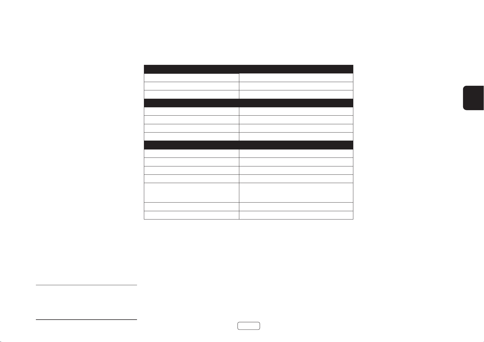
PA410
Dauerleistung @ 0.2% THD pro Kanal
Vier Kanäle angesteuert, 4 Ω / 8 Ω, 1 kHz 70W / 50W
Zwei Kanäle angesteuert, 4 Ω / 8 Ω, 1 kHz 90W / 60W
Klirrfaktor, 80% Leistung, 8 Ω bei 1 kHz 0.003%
Eingänge
Eingangsempfindlichkeit 50 W / 8 Ω 560mV RMS
Signal-Rausch-Verhältnis (A-bwt) 50 W / 8 Ω 106dB
Eingangsimpedanz 10kΩ
Frequenzgang 20 - 20kHz +/-0.05dB
Allgemein
Netzspannung 110–120V or 220–240V, 50–60Hz
Maximale Leistungsaufnahme 700W
Geringer Stromverbrauch im Standby 0.5W
Netzwerk Standby Verbrauch 2W
Abmessungen B x H x T (einschließlich
Füßen, Bedienelementen und
Lautsprecherklemmen)
Gewicht (netto) 10kg
Gewicht (brutto) 11.5kg
433x325x105mm
DE
Alle angegebenen Werte sind typisch, sofern
nicht anders angegeben. Arcam bemüht sich um
ständige Produktverbesserung. Das Design und die
technischen Daten können sich deshalb ohne weitere
Ankündigung ändern. Fehler und Auslassungen
vorbehalten
DE-19
Page 64

Weltweite Garantie
Hiermit haben Sie in den ersten fünf Jahren nach dem Kauf Anspruch auf eine kostenlose Reparatur Ihres Geräts,
vorausgesetzt, Sie haben es ursprünglich bei einem autorisierten Arcam-Händler erworben. Der Arcam-Fachhändler
führt den Kundenservice nach Vertragsschluss durch. Der Hersteller übernimmt keine Verantwortung für Schäden,
die durch Unfall, falsche Nutzung, Verschleiß, Vernachlässigung oder unzulässige Veränderungen bzw. Reparaturen
entstehen. Außerdem wird keinerlei Verantwortung für Schäden oder Verlust des Gerätes während des Transports
zum oder vom Garantienehmer übernommen.
Die Garantie umfasst Folgendes:
Teile (ausgenommen Laufwerke) und Arbeitskosten für fünf Jahre ab Kaufdatum (siehe unten für zusätzliche
Bedingungen). Nach fünf Jahren müssen Sie sowohl Teile als auch Arbeitskosten bezahlen.
Laufwerke (jeder Art) unterliegen dieser Garantie für zwei Jahre ab Kaufdatum.
Die Garantie deckt zu keinem Zeitpunkt den Austausch von Batterien/Akkus ab.
Versandkosten werden nicht übernommen.
Inanspruchnahme der Garantie
Das Gerät sollte in der Originalverpackung an den Händler zurückgegeben werden, bei dem es erworben wurde.
Der Versand muss frei Haus durch einen angesehenen Kurier erfolgen – nicht mit der Post. Da keine Verantwortung
für Schäden oder Verlust während des Transports zum Händler oder Distributor übernommen wird, sollten Sie das
Gerät entsprechend versichern.
Weitere Informationen zu Arcam erhalten Sie unter arcam.support@harman.co.uk.
Probleme?
Kann Ihr Arcam-Händler Fragen zu diesem oder einem anderen Arcam-Produkt nicht beantworten, wenden Sie sich
an den Arcam-Kundendienst, und wir versuchen unser Möglichstes, um Ihnen zu helfen.
Online-Registrierung
Sie können Ihr Produkt online auf www.arcam.co.uk registrieren.
DE-20
Page 65

EINDVERSTERKER
HANDLEIDING
NL
PA720 / PA240 / PA410
Page 66

Welkom
Hartelijk bedankt en gefeliciteerd...
...voor het aanschaffen van uw Arcam PA720, PA240 or PA410 eindversterker.
Arcam produceert al langer dan vier decennia specialistische audioproducten van buitengewone kwaliteit en de
nieuwe PA720, PA240 and PA410 eindversterkers zijn de nieuwste in een lange reeks bekroonde hifi. Het ontwerp
van het HDA-assortiment is gebaseerd op alle ervaringen van Arcam als een van de meest gerespecteerde
audiobedrijven in het Verenigd Koninkrijk, om Arcam's best presterende assortiment meerkanaals eindversterkers
te produceren - ontworpen en gebouwd om u jarenlang luisterplezier te geven.
Deze handleiding helpt u bij het installeren en gebruiken van de PA720, PA240 and PA410 en bevat informatie over
de meer geavanceerde eigenschappen. Gebruik de inhoudsopgave op de volgende pagina om de gewenste sectie
te vinden.
Wij hopen dat u jarenlang probleemloos van uw product zult genieten. In het onwaarschijnlijke geval dat het
systeem defect raakt of indien u meer informatie wilt ontvangen over producten van Arcam, dan zijn de dealers van
ons netwerk u graag van dienst. U kunt ook meer informatie vinden op de website van Arcam www.arcam.co.uk.
Uw PA720, PA240 and PA410 ontwikkelingsteam
NL-2
Page 67

Inhoudsopgave
Welkom NL-2
Overzicht NL-4
Het apparaat plaatsen NL-4
Aansluitkabels NL-4
Voeding NL-4
Aansluiten en bedieningen op het achterpaneel PA720 NL-5
Aansluiten en bedieningen op het achterpaneel PA240 NL-6
Aansluiten en bedieningen op het achterpaneel PA410 NL-7
Aansluitingen van het bedieningssysteem NL-8
Netwerk en RS232 NL-8
USB NL-8
Trigger IN/UIT NL-8
Aansluitingen en bedieningen van het voorpaneel NL-9
Gebruik NL-10
Inschakelen NL-10
Automatische stand-by NL-10
Netwerk en RS322 op stand-by NL-10
De uitgang dempen NL-10
Modusschakelaars NL-10
Bronnen en luidsprekers aansluiten NL-11
Bridged mono modus - alleen PA240 NL-14
Dual mono / biamp modus - alleen PA240 NL-15
Probleemoplossing NL-16
Specicaties NL-17
PA720 NL-17
PA240 NL-18
PA410 NL-19
Wereldwijde garantie NL-20
NL
NL-3
Page 68

Overzicht
Arcam’s PA720, PA240 and PA410
versterkers
Arcam’s PA720, PA240 and PA410 eindversterkers
bieden een toonaangevende geluidskwaliteit voor een
optimale weergave van uw muziek.
Gebaseerd op de vele jaren ervaring in versterkerontwerp
bij Arcam, maken deze producten gebruik van de beste
kwaliteit componenten en technische praktijk om
versterkers te produceren die vele jaren muzikaal genot
en betrouwbare dienst zullen bieden.
Met een toroïdale voeding, een akoestisch gedempt
chassis, klasse G-technologie (PA240 & PA720),
parallelle transistoruitgangstrappen (PA240) en
uitzonderlijk lage vervormings- en ruisniveaus, zijn alle
PA720, PA240 and PA410 versterkers in staat om muziek
te reproduceren met alle originele autoriteit en details.
U zult zonder twijfel de muziek horen net zoals de
artiest wilt dat u het hoort.
De PA720, PA240 and PA410 versterkers zijn ontworpen
voor uiterst hoge prestaties waardoor uw muziek pas
echt tot leven komt.
PA720
POWER AMPLIFIER
POWER
STANDBYMUTE
Het apparaat plaatsen
Plaats de versterker op een vlakke, stevige
ondergrond, vermijd direct zonlicht en vocht- en
warmtebronnen.
Plaats de PA720, PA240 or PA410 niet bovenop een
eindversterker of andere hittebron.
Plaats de versterker niet in een gesloten ruimte zoals
een boekenkast of een afgesloten kast, tenzij er een
goede ventilatie is. De PA720, PA240 and PA410 zijn
ontworpen om warm te worden tijdens normaal
gebruik.
Plaats geen ander component of voorwerp bovenop
de versterker, omdat dit de luchtstroom rond
het koellichaam kan belemmeren, waardoor de
versterker te heet wordt. (Het apparaat bovenop de
versterker geplaatst zal ook warm worden.)
Plaats geen platenspeler op dit apparaat.
Platenspelers zijn zeer gevoelig voor het geluid
dat wordt geproduceerd door apparaten die op
het lichtnet zijn aangesloten en dit vertaalt zich in
achtergrondgeruis als de platenspeler te dichtbij
staat.
De normale functie van het apparaat kan worden
verstoord door krachtige, elektromagnetische
interferentie. Mocht dit het geval zijn, dan hoeft u het
apparaat slechts terug te stellen met de aan/uittoets
of deze naar een andere plek te verplaatsen.
NL-4
Aansluitkabels
Wij raden u aan om afgeschermde kabels van hoge
kwaliteit te gebruiken die speciaal voor dit doel
ontwikkeld zijn. Andere kabels hebben andere
impedantie-eigenschappen die de prestaties van uw
systeem zullen verminderen (gebruik bijvoorbeeld
geen videokabels om audiosignalen door te geven).
Alle kabels moeten zo kort mogelijk gehouden worden.
Het is een goede gewoonte om ervoor te zorgen dat u
bij het installeren van uw apparatuur het netsnoer zo
ver mogelijk van uw audiokabels verwijderd houdt. Dit
kan namelijk ongewenst geruis in de audiosignalen tot
gevolg hebben.
Voeding
De versterker is uitgerust met een gegoten netstekker.
Controleer of de stekker in uw stopcontact past –
indien u een andere stekker nodig hebt, dient u met uw
Arcam-dealer contact op te nemen.
Neem onmiddellijk contact op met uw Arcam-dealer als
de voedingsspanning of netstekker bij u afwijkt.
Steek het IEC-stekkereinde van het netsnoer in de
opening aan de achterkant van de versterker en
controleer of deze stevig vast zit. Steek het andere
uiteinde van de kabel in uw stopcontact en schakel het
stopcontact in.
Page 69

Aansluiten en bedieningen op het achterpaneel PA720
GEBALANCEERDE XLR-AUDIO-INGANGEN
Sluit de XLR-uitgangen aan van uw
voorversterker.
Zie “Bronnen en luidsprekers aansluiten” op
pagina NL-11.
IN7
IN6
IN5
IN4
IN3
OUT7
OUT6
OUT5
OUT4
OUT3
IN2
OUT2
INGANGSCHAKELAARS
U kunt hiermee de PA720 configureren
voor verschillende ingangtypes.
Zie “Bronnen en luidsprekers aansluiten”
op pagina NL-11.
IN1
OUT1
IN7 IN6 IN5 IN4 IN3 IN2 IN1
CH5CH6CH7
CH4 CH3 CH2 CH1
USB
Alleen voor
software-upgrades. Zie “USB”
op pagina NL-8.
4-16 OHMSCLASS 2 WIRING
U kunt met Trigger IN de PA720 laten in- of uitschakelen door een externe bron.
U kunt met Trigger UIT de PA720 gebruiken om de aan/uit-status van andere
aangesloten apparatuur te regelen.
Zie “Trigger IN/UIT” op pagina NL-8.
TRIGGER IN
USB
5V
100mA
TRIGGER OUT
(12V 100mA)
SUPPLY
VOLTAGE
SWITCH POSITIONS
115 = 110 - 120V ~
230 = 220 - 240V ~
RCA
INPUT
XLR
RS232 NET
POWER INLET
110-120V/220-240V~
50/60Hz 1.5kW MAX
NL
TRIGGER IN/UIT
VOORVERSTERKERINGANGEN
Sluit de phono-uitgangen
aan van uw voorversterker.
Zie “Bronnen en luidsprekers
aansluiten” op pagina NL-11.
VOORVERSTERKERUITGANG
OUT1-OUT7 verstrekt een kopie van het
signaal toegepast op alleen de IN1-IN7
phono-aansluitingen, niet op de XLR.
Opmerking: Dit is een passieve
uitgang, er wordt geen extra
filter of versterking toegepast.
LUIDSPREKERKLEMMEN
Zie “Bronnen en
luidsprekers aansluiten” op
pagina NL-11.
Dankzij deze aansluiting kunt u de
RS232
afstandsbediening van een ander Home
Automation Systeem of van een andere
computer gebruiken.
Zie “Netwerk en RS232” op pagina NL-8.
Dankzij deze aansluiting kunt u de
NETWERK
afstandsbediening van een ander Home
Automation Systeem of van een andere
computer gebruiken.
Zie “Netwerk en RS232” op pagina NL-8.
NL-5
VOEDINGSINGANG
Sluit hier het correcte
netsnoer op aan.
Lees de paragrafen “Het apparaat plaatsen”,
“Voeding” en “Aansluitkabels” op pagina
NL-4 voordat u uw PA720 versterker
aansluit!
SPANNINGSELECTIE
Controleer of de geselecteerde
spanning overeenkomt met de
plaatselijke voeding.
Page 70

Aansluiten en bedieningen op het achterpaneel PA240
RS232 NET
TRIGGER OUT
(12V 100mA)
TRIGGER IN
POWER INLET
110-120V/220-240V~
50/60Hz 1.5kW MAX
USB
5V
100mA
SWITCH POSITIONS
115 = 110 - 120V ~
230 = 220 - 240V ~
SUPPLY
VOLTAGE
RCA
XLR
INPUT
+
4-16 OHMS. CLASS 2 WIRING
+
- -
R
ST BRIDGE DM
GAIN
25dB 31dB
MODE
L
INR INL
INR
OUTR
INL
OUTL
GEBALANCEERDE XLR-AUDIO-INGANGEN
Sluit de XLR-uitgangen aan van uw
voorversterker.
Zie “Bronnen en luidsprekers aansluiten” op
pagina NL-11.
INGANGSCHAKELAARS
U kunt hiermee de PA240 configureren
voor verschillende gebruiksmodi.
Zie “Bronnen en luidsprekers aansluiten”
op pagina NL-11.
USB
Alleen voor
software-upgrades. Zie “USB”
op pagina NL-8.
U kunt met Trigger IN de PA240 laten in- of uitschakelen door een externe bron.
TRIGGER IN/UIT
U kunt met Trigger UIT de PA240 gebruiken om de aan/uit-status van andere
aangesloten apparatuur te regelen.
Zie “Trigger IN/UIT” op pagina NL-8.
VOORVERSTERKERINGANGEN
LUIDSPREKERKLEMMEN
Sluit de phono-uitgangen
aan van uw voorversterker.
Zie “Bronnen en luidsprekers
aansluiten” op pagina NL-11.
luidsprekers aansluiten” op
VOORVERSTERKERUITGANG
OUTL en OUTR verstrekken een kopie van
het signaal toegepast op alleen de IN L en
IN R phono-aansluitingen, niet op de XLR.
Opmerking: Dit is een passieve
uitgang, er wordt geen extra filter
of versterking toegepast.
Zie “Bronnen en
pagina NL-11.
RS232
Dankzij deze aansluiting kunt u de
afstandsbediening van een ander Home
Automation Systeem of van een andere
computer gebruiken.
Zie “Netwerk en RS232” op pagina NL-8.
Dankzij deze aansluiting kunt u de
afstandsbediening van een ander Home
Automation Systeem of van een andere
Zie “Netwerk en RS232” op pagina NL-8.
NL-6
NETWERK
computer gebruiken.
VOEDINGSINGANG
Sluit hier het correcte
netsnoer op aan.
SPANNINGSELECTIE
Controleer of de geselecteerde
spanning overeenkomt met de
plaatselijke voeding.
Lees de paragrafen “Het apparaat plaatsen”,
“Voeding” en “Aansluitkabels” op pagina
NL-4 voordat u uw PA240 versterker
aansluit!
Page 71

POWER INLET
110-120V/220-240V ~ 50/60Hz
500W MAX
SUPPLY
VOLTAGE
SWITCH POSITIONS
115 = 110 - 120V ~
230 = 220 - 240V ~
RS232NET USB
5V 100mA
CH1
4-16 OHMS
CLASS 2 WIRING
CH2CH3CH4
IN4
OUT4
IN3
OUT3
IN2
OUT2
IN1
OUT1
TRIGGER OUT
(12V 100mA)
TRIGGER IN
Aansluiten en bedieningen op het achterpaneel PA410
Controleer of de geselecteerde
spanning overeenkomt met de
VOEDINGSINGANG
Sluit hier het correcte
netsnoer op aan.
SPANNINGSELECTIE
plaatselijke voeding.
Sluit uw lokale bekabeld netwerk aan op één
poort. De tweede poort kan worden gebruikt
om andere apparatuur aan te sluiten.
Zie “Netwerk en RS232” op pagina NL-8.
Dankzij deze aansluiting kunt
RS232
u de afstandsbediening van
een ander Home Automation
Systeem of van een andere
computer gebruiken.
Zie “Netwerk en RS232” op
pagina NL-8.
NETWERK
Alleen voor software-upgrades.
USB
Zie “USB” op pagina NL-8.
VOORVERSTERKERINGANGEN
Sluit de phono-uitgangen aan van uw
voorversterker.
Zie “Bronnen en luidsprekers
aansluiten” op pagina NL-11.
VOORVERSTERKERUITGANG
OUT1 naar OUT4 verstrekt een kopie
van het signaal toegepast op de
IN1 naar IN4 phono-aansluitingen.
Opmerking: Dit is een passieve
uitgang, er wordt geen extra
filter of versterking toegepast.
NL-7
U kunt met Trigger IN de PA410 laten in- of uitschakelen door een externe bron.
TRIGGER IN/UIT
U kunt met Trigger UIT de PA410 gebruiken om de aan/uit-status van andere
aangesloten apparatuur te regelen.
Zie “Trigger IN/UIT” op pagina NL-8.
LUIDSPREKERKLEMMEN
Zie “Bronnen en
luidsprekers aansluiten” op
pagina NL-11.
Lees de paragrafen “Het apparaat plaatsen”,
“Voeding” en “Aansluitkabels” op pagina
NL-4 voordat u uw PA410 versterker
aansluit!
NL
Page 72

RS232 NET
TRIGGER OUT
(12V 100mA)
TRIGGER IN
POWER INLET
110-120V/220-240V~
50/60Hz 1.5kW MAX
USB
5V
100mA
SWITCH POSITIONS
115 = 110 - 120V ~
230 = 220 - 240V ~
SUPPLY
VOLTAGE
RCA
XLR
INPUT
IN7
OUT7
IN6
OUT6
IN5
OUT5
IN4
OUT4
IN3
OUT3
IN2
OUT2
IN1
OUT1
IN7 IN6 IN5 IN4 IN3 IN2 IN1
CH4 CH3 CH2 CH1
4-16 OHMSCLASS 2 WIRING
CH5CH6CH7
Aansluitingen van het
bedieningssysteem
Netwerk en RS232
De PA720, PA240 and PA410 is voorzien van een
netwerk- en RS232-poort die kunnen worden gebruikt
om een lokaal netwerk, computer of systeem voor
huisautomatisering aan te sluiten, zodat de versterker
op afstand kan worden bediend en gecontroleerd.
Er zijn verschillende systemen van derden verkrijgbaar
waarmee u al uw entertainmentapparatuur op
geavanceerde wijze kunt bedienen. Neem contact op
met uw dealer of installateur voor meer informatie.
Raadpleeg voor technische details van controleprotocollen
het PA720 / PA240 / PA410 RS232/IP bedieningsdocument,
beschikbaar voor download op www.arcam.co.uk, voor
meer informatie.
Opmerking: Netwerk- en RS232-bediening is
standaard uitgeschakeld in stand-by-modus om het
stroomverbruik te minimaliseren. Zie “Netwerk en RS322
op stand-by” op pagina NL-10 om de netwerkbediening
in te schakelen.
STB/MHL
STB
Z2 OUT
L
R
HEIGHT1 HEIGHT2
L
R
PREAMP OUT
FL C SL SBL
FR SUB 1 SR SBR
Netwerkrouter
GAME
GAME
SUB 2
AV
HDMI
AV
ANALOGUE AUDIO
BD
BD
SAT
PVR
FL C SL SBL HEIGHT 1 L HEIGHT 2 L
FR SUB 1 SR SBR HEIGHT 1 R HEIGHT 2 R
CD
BD CD
VCR
DIGITAL AUDIO
PVRSAT
STB AV
BALANCED OUTPUTS
1 2 3 4NET
PVR
ETHERNET
ZONE 2
OUT
USB 5V
OUTPUT 1
OUTPUT 2
ARC
FM/DAB
DC 6V
1A
1.2A MAX
POWER INLET
~50/60Hz 50W MAX
115 230
SWITCH POSITIONS
115 = 110 - 115V~
230 = 220 - 240V~
TRIG Z1 Z1 IR
RS232
TRIG Z2 Z2 IR
23425
AV860
Controller voor thuisautomatisering
RS232
USB
Deze USB-poort wordt alleen gebruikt voor softwareupdates. Ga naar www.arcam.co.uk voor de nieuwste
software en meer informatie.
Trigger IN/UIT
De aan/uit-status van de PA720, PA240 and PA410
kan door compatibele audio-/videobronnen worden
bediend (zoals een Arcam AVR). Sluit in dit geval de
TRIGGER OUT van de bron aan op de TRIGGER IN van
de PA720, PA240 or PA410 met een mono 3,5 mm kabel.
De PA720, PA240 and PA410 kan natuurlijk ook de aan/
uit-status bedienen van andere compatibele apparatuur
(zoals een andere PA720, PA240 or PA410). Sluit in dit
geval de TRIGGER IN van de bron aan op de TRIGGER
OUT van de PA720, PA240 or PA410 met een mono
3,5 mm kabel.
Opmerking: Deze kabels zijn niet inbegrepen.
Controller voor thuisautomatisering
POWER INLET
110-120V/220-240V ~ 50/60Hz
500W MAX
SUPPLY
VOLTAGE
SWITCH POSITIONS
115 = 110 - 120V ~
230 = 220 - 240V ~
NET
RS232NET USB
5V 100mA
TRIGGER IN
TRIGGER OUT
(12V 100mA)
PA720
IN4
IN3
OUT4
OUT3
NL-8
CH2CH3CH4
CH1
IN2
IN1
OUT2
OUT1
CLASS 2 WIRING
4-16 OHMS
PA410
Page 73

Aansluitingen en bedieningen van het voorpaneel
STROOMINDICATOR EN AAN-/
UITSCHAKELAAR
Zie “Inschakelen” op pagina NL-10.
POWER AMPLIFIER
NL
PA720
De PA720, PA240 or PA410 luidsprekeruitgangen
DEMPEN
dempen/herstellen.
Zie “De uitgang dempen” op pagina NL-10.
NL-9
POWER
STANDBYMUTE
APPARAAT STAND-BY
Zie “Inschakelen” op pagina NL-10.
Page 74

Gebruik
Inschakelen
De POWER-toets op het voorpaneel schakelt het
apparaat aan en uit. De statusindicator-LED toont
de status van de versterker: het verandert van rood
in oranje en vervolgens in wit als de netvoeding is
aangesloten en het apparaat is ingeschakeld.
Druk op de toets STBY terwijl het apparaat is
ingeschakeld om de PA720, PA240 or PA410 op de
stand-by-modus te schakelen. Druk nogmaals op de
toets STBY om het apparaat vanuit de stand-by-modus
weer in te schakelen.
Automatische stand-by
Om te voldoen aan internationale richtlijnen met
betrekking tot consumentenproducten, is dit apparaat
ontworpen om op stand-by te schakelen wanneer
er geen interactie met de gebruiker is en er voor
een langere tijd geen audio-ingangssignaal wordt
waargenomen (standaard is 20 minuten). Het apparaat
kan vanuit stand-by worden ingeschakeld door op
de toets STBY op het voorpaneel te drukken, via de
triggeringang of via een RS232- of ethernetcommando
(indien ingeschakeld, zie “Netwerk en RS322 op standby” voor meer informatie).
De tijd voor het automatisch op stand-by schakelen
kan via RS232- of IP-besturingscommando’s worden
aangepast. Raadpleeg het PA720 / PA240 / PA410
RS232-/IP-besturingsdocument, beschikbaar voor
download op www.arcam.co.uk.
Als u de MUTE-knop ingedrukt houdt, schakelt u de
standby-tijd tussen OFF en 20 minuten.
De LED knippert om de wijziging van de instelling aan
te geven, rood voor UIT, groen gedurende 20 minuten.
Opmerking: als de stand-by-tijd op UIT is ingesteld,
dan zal de automatische stand-by-functie worden
uitgeschakeld.
Netwerk en RS322 op stand-by
De netwerk- en RS322-functionaliteit wordt
uitgeschakeld in de laag-vermogen stand-by-modus.
U kunt de netwerk- en RS232-functionaliteit op
stand-by inschakelen door een besturingscommando
of startverzoek naar het apparaat te sturen terwijl deze
is ingeschakeld.
Hierdoor zal de besturingsmodus worden ingeschakeld
die het laatst was gebruikt met het apparaat op
stand-by.
Opmerking: Om aan te geven dat het apparaat niet
op stand-by staat met het laagste energieverbruik, zal
de led eventjes knipperen wanneer het apparaat op
stand-by wordt geschakeld.
Opmerking: Het energieverbruik in de stand-by-modus
neemt toe als u de netwerk- of RS232-besturing inschakelt.
Om het apparaat weer terug in te stellen op de standaard
laag-vermogen stand-by-functie, houdt u de toets STBY
minstens 3 seconden ingedrukt of herstelt u de standaard
fabriekswaarden van het apparaat.
De uitgang dempen
De luidsprekeruitgangen van de PA720, PA240 or PA410
kunnen worden gedempt door op de toets
MUTE op het voorpaneel te drukken of door het
betreffende commando te sturen via de RS232- of
netwerkverbinding.
Als het apparaat is gedempt, dan zal de aan/uit-indicator
op het voorpaneel oranje beginnen te branden.
Om de dempfunctie te annuleren, drukt u nogmaals op
de toets MUTE of stuurt u het betreffende commando
via de RS232- of netwerkverbinding.
Modusschakelaars
U kunt de verschillende modusschakelaars op de
achterzijde van de PA720 en PA240 versterkers gebruiken
om uw eindversterker voor uw specifiek apparatuur te
configureren. Zie “Bronnen en luidsprekers aansluiten”
op pagina NL-11 voor meer informatie.
INPUT (alleen PA720 en PA240)
Deze schakelaar wisselt tussen de XLR en RCA
phono-ingangen van de versterker. Selecteer welk type
aansluiting u gebruikt wanneer u uw voorversterker
aansluit.
GAIN (alleen PA240)
U kunt met deze schakelaar de gain veranderen van de
standaard Arcam gain van 31 dB (hetzelfde voor alle
versterkers en ontvangers van Arcam) in 26 dB. Dit biedt
flexibiliteit wanneer u meerdere PA240 versterkers in
verschillende modi aansluit op meerdere luidsprekers.
Deze schakelaar dient voor een normale installatie op
31 dB te worden gelaten.
MODE (alleen PA240)
Deze schakelaar wisselt tussen de verschillende
versterkingsmodi van de PA240.
STEREO (ST)
Dit is de standaard stereo versterkingsmodus waarin
twee afzonderlijke voorversterkingsingangen worden
gebruikt die twee afzonderlijke luidsprekeruitgangen
aandrijven.
DUAL MONO (DM)
U kunt met deze modus een enkele
voorversterkingsingang twee afzonderlijke luidsprekers
laten aandrijven.
De twee drivers van een enkele luidsprekers kunnen
bovendien worden bi-amped vanaf een enkele PA240.
NL-10
BRIDGED MONO (BRIDGE)
Deze modus gebruikt beide kanalen van de PA240 om
een enkele luidspreker aan te drijven. Dit is de ultieme
hoog-vermogen versterking van uiterst hoge kwaliteit.
Page 75

Bronnen en luidsprekers aansluiten
RS232 NET
TRIGGER OUT
(12V 100mA)
TRIGGER IN
POWER INLET
110-120V/220-240V~
50/60Hz 1.5kW MAX
USB
5V
100mA
SWITCH POSITIONS
115 = 110 - 120V ~
230 = 220 - 240V ~
SUPPLY
VOLTAGE
RCA
XLR
INPUT
IN7
OUT7
IN6
OUT6
IN5
OUT5
IN4
OUT4
IN3
OUT3
IN2
OUT2
IN1
OUT1
IN7 IN6 IN5 IN4 IN3 IN2 IN1
CH4 CH3 CH2 CH1
4-16 OHMSCLASS 2 WIRING
CH5CH6CH7
PREAMP OUT
SUB 1
HEIGHT 1 L
HEIGHT 2 L
SUB 1
HEIGHT 1 R
HEIGHT 2 R
PA720
Sluit de RODE positieve luidsprekerklem gemarkeerd
CH1 tot CH7+ aan op de positieve klem van uw
luidspreker. Evenzo, sluit de ZWARTE negatieve
luidsprekerklem van hetzelfde kanaal aan op de
negatieve klem van uw luidspreker.
Herhaal deze stappen voor de andere luidsprekers en
gebruik daarbij dezelfde overeenkomende ingang en
luidsprekerklemmen voor elk kanaal.
Opmerking: Alle kanalen zijn identiek, waardoor het
dus niet nodig is om specifieke AVR-uitgangskanalen
aan te sluiten op specifieke versterkerkanalen.
AV860
FL C SL SBL
FR
SR SBR
STB/MHL
STB
Z2 OUT
L
R
HEIGHT1 HEIGHT2
L
R
PREAMP OUT
FL C SL SBL
FR SUB 1 SR SBR
GAME
GAME
SUB 2
AV
HDMI
AV
ANALOGUE AUDIO
BD
BD
SAT
CD
PVR
PVRSAT
BD CD
FL C SL SBL HEIGHT 1 L HEIGHT 2 L
FR SUB 1 SR SBR HEIGHT 1 R HEIGHT 2 R
BALANCED OUTPUTS
FL C SL SBL
FR
VCR
DIGITAL AUDIO
STB AV
OUT
ETHERNET
USB 5V
SR SBR
ZONE 2
PVR
BALANCED OUTPUTS
OUTPUT 1
OUTPUT 2
ARC
FM/DAB
DC 6V
1A
1.2A MAX
POWER INLET
~50/60Hz 50W MAX
115 230
SWITCH POSITIONS
115 = 110 - 115V~
230 = 220 - 240V~
TRIG Z1 Z1 IR
RS232
TRIG Z2 Z2 IR
23425
Opmerking: Apparaat
dient aangesloten te
zijn via RCA of XLR.
Beide afgebeelde
versies dienen slechts
ter illustratie.
INPUT
XLR
RCA
NL
Opmerking: Eén kanaal getoond
voor duidelijkheid
Opmerkingen m.b.t. het maken van
luidsprekeraansluitingen
Maak geen aansluitingen met een versterker terwijl deze is ingeschakeld. Het is raadzaam
dat uw versterker volledig losgekoppeld is van de netvoeding voordat u begint.
Controleer alle verbindingen grondig na het aansluiten op luidsprekers voordat u uw
versterker(s) voor de eerste keer inschakelt. Zorg ervoor dat blootliggende draden of kabels
elkaar of het chassis van de versterker niet aanraken (dat zou kortsluiting kunnen veroorzaken)
en dat u positief (+) naar positief en negatief (–) naar negatief hebt aangesloten. Zorg ervoor
de bedrading voor zowel de versterker en de luidspreker te controleren.
Nadat de aansluitingen tot stand zijn gebracht: schakel de versterker in en verhoog het
volume vervolgens geleidelijk aan tot op het gewenste luisterniveau.
Als u twijfelt over hoe uw systeem dient te worden aangesloten, neem dan a.u.b.
contact op met uw Arcam dealer, zij staan u graag te hulp.
PA720
HF
LF
HF
LF
NL-11
HF
LF
HF
LF
HF
LF
HF
LF
HF
LF
Page 76

PA240
RCA
XLR
INPUT
+
4-16 OHMS. CLASS 2 WIRING
+
- -
R
ST BRIDGE DM
GAIN
25dB 31dB
MODE
L
INR INL
INR
OUTR
INL
OUTL
PREAMP OUT
CSLSBL
SUB 1SRSBR
Sluit de RODE positieve luidsprekerklem gemarkeerd
L+ aan op de positieve klem van uw luidspreker.
Evenzo, sluit de ZWARTE negatieve luidsprekerklem
gemarkeerd L aan op de negatieve klem van uw
luidspreker.
Herhaal deze stappen voor de rechter luidspreker.
Opmerking: Apparaat dient aangesloten te zijn
via RCA of XLR. Beide afgebeelde versies dienen
slechts ter illustratie.
FL
FR
STB/MHL
STB
Z2 OUT
L
R
HEIGHT1 HEIGHT2
L
R
PREAMP OUT
FL C SL SBL
FR SUB 1 SR SBR
GAME
GAME
SUB 2
AV
HDMI
AV
ANALOGUE AUDIO
BD
BD
SAT
CD
PVR
PVRSAT
BD CD
FL C SL SBL HEIGHT 1 L HEIGHT 2 L
FR SUB 1 SR SBR HEIGHT 1 R HEIGHT 2 R
BALANCED OUTPUTS
Opmerking:
Zorg ervoor dat de INPUT-schakelaar is ingesteld op
FL
ingangstype RCA of XLR
Zorg ervoor de GAIN-schakelaar in te stellen op 31dB
Zorg ervoor dat de MODE-schakelaar is ingesteld op
stereo modus, ST
FR
VCR
DIGITAL AUDIO
STB AV
PVR
ETHERNET
25dB 31dB
ZONE 2
OUT
USB 5V
OUTPUT 1
OUTPUT 2
ARC
FM/DAB
DC 6V
1A
1.2A MAX
POWER INLET
~50/60Hz 50W MAX
115 230
SWITCH POSITIONS
115 = 110 - 115V~
230 = 220 - 240V~
TRIG Z1 Z1 IR
RS232
TRIG Z2 Z2 IR
23425
AV860
GAIN
INPUT
XLR
RCA
MODE
ST BRIDGE DM
Rechts
HF
LF
Links
HF
LF
PA240
NL-12
Page 77

PA410
POWER INLET
110-120V/220-240V ~ 50/60Hz
500W MAX
SUPPLY
VOLTAGE
SWITCH POSITIONS
115 = 110 - 120V ~
230 = 220 - 240V ~
RS232NET USB
5V 100mA
CH1
4-16 OHMS
CLASS 2 WIRING
CH2CH3CH4
IN4
OUT4
IN3
OUT3
IN2
OUT2
IN1
OUT1
TRIGGER OUT
(12V 100mA)
TRIGGER IN
SUB 2
Sluit de RODE positieve luidsprekerklem gemarkeerd
CH1 tot CH4+ aan op de positieve klem van uw
luidspreker. Evenzo, sluit de ZWARTE negatieve
luidsprekerklem van hetzelfde kanaal- aan op de
negatieve klem van uw luidspreker.
AV860
STB/MHL
STB
Z2 OUT
L
R
HEIGHT1 HEIGHT2
L
R
PREAMP OUT
FL C SL SBL
FR SUB 1 SR SBR
GAME
GAME
SUB 2
AV
HDMI
AV
ANALOGUE AUDIO
BD
BD
SAT
PVR
FL C SL SBL HEIGHT 1 L HEIGHT 2 L
FR SUB 1 SR SBR HEIGHT 1 R HEIGHT 2 R
CD
BD CD
VCR
DIGITAL AUDIO
PVRSAT
STB AV
BALANCED OUTPUTS
ZONE 2
PVR
OUT
ETHERNET
USB 5V
OUTPUT 1
OUTPUT 2
ARC
FM/DAB
DC 6V
1A
1.2A MAX
POWER INLET
~50/60Hz 50W MAX
115 230
SWITCH POSITIONS
115 = 110 - 115V~
230 = 220 - 240V~
TRIG Z1 Z1 IR
RS232
TRIG Z2 Z2 IR
23425
Herhaal deze stappen voor de andere luidsprekers en
gebruik daarbij dezelfde overeenkomende ingang en
luidsprekerklemmen voor elk kanaal.
Opmerking: Alle kanalen zijn identiek, waardoor het
dus niet nodig is om specifieke AVR-uitgangskanalen
aan te sluiten op specifieke versterkerkanalen.
PA410
HEIGHT 1 HEIGHT 2
L
NL
R
PREAMP OUT
HF
LF
Hoogte 1 Rechts Hoogte 1 Links
NL-13
HF
LF
Hoogte 2 Rechts Hoogte 2 Links
HF
LF
HF
LF
Page 78

Bridged mono modus - alleen
RCA
XLR
INPUT
+
4-16 OHMS. CLASS 2 WIRING
+
- -
R
ST BRIDGE DM
GAIN
25dB 31dB
MODE
L
INR INL
INR
OUTR
INL
OUTL
RCA
XLR
INPUT
+
4-16 OHMS. CLASS 2 WIRING
+
- -
R
ST BRIDGE DM
GAIN
25dB 31dB
MODE
L
INR INL
INR
OUTR
INL
OUTL
PREAMP OUT
CSLSBL
SUB 1SRSBR
PA240
Bridged mono modus vereist het gebruik van een
PA240 voor elk kanaal.
Opmerking: In bridged modus zijn alleen de L+ en R+
luidsprekeruitgangen vereist.
WAARSCHUWING: Maak geen aansluitingen op de
luidsprekerklemmen gemarkeerd L- of R-, anders zult
u uw versterker ernstig beschadigen.
Opmerking: Apparaat dient aangesloten te zijn
via RCA of XLR. Beide afgebeelde versies dienen
slechts ter illustratie.
Rechts
HF
Op een van de PA240’s, sluit de RODE positieve
luidsprekerklem gemarkeerd L+ aan op de positieve
klem van uw linker luidspreker.
Sluit de RODE positieve luidsprekerklem gemarkeerd
R+ aan op de negatieve klem van uw linker luidspreker.
Herhaal deze stappen voor de rechter luidspreker en
gebruik daarbij DEZELFDE klemmen op de andere
PA240.
FL
FR
FL
FR
Opmerking: L+ moet worden aangesloten op de
positieve luidsprekerklem en R+ op de negatieve
luidsprekerklem op BEIDE luidsprekers, anders zullen de
luidsprekers buiten fase zijn.
WAARSCHUWING: Het is ESSENTIEEL dat u de L+ en R+
klemmen hebt gebruikt van de PA240. L- en R- klemmen
zijn NIET vereist in deze opstelling.
STB/MHL
STB
Z2 OUT
L
R
HEIGHT1 HEIGHT2
L
R
PREAMP OUT
FL C SL SBL
FR SUB 1 SR SBR
GAME
GAME
SUB 2
AV
HDMI
AV
ANALOGUE AUDIO
BD
BD
SAT
CD
PVR
FL C SL SBL HEIGHT 1 L HEIGHT 2 L
FR SUB 1 SR SBR HEIGHT 1 R HEIGHT 2 R
VCR
DIGITAL AUDIO
PVRSAT
BD CD
STB AV
BALANCED OUTPUTS
AV860
Er is in deze opstelling slechts één onderlinge aansluiting
nodig op elke eindversterker en deze dient te worden
aangesloten op de ingang IN L. De onderlinge
verbindingen kunnen of XLR (aanbevolen voor langere
kabels) of phono (RCA) zijn. Stel de INPUT-schakelaar op
beide van de PA240’s ib op de juiste instelling voor de
gebruikte kabels.
Opmerking: De ingang IN R heeft geen functie in deze
opstelling.
PVR
ETHERNET
ZONE 2
OUT
USB 5V
OUTPUT 1
OUTPUT 2
ARC
FM/DAB
DC 6V
1A
1.2A MAX
POWER INLET
~50/60Hz 50W MAX
115 230
SWITCH POSITIONS
115 = 110 - 115V~
230 = 220 - 240V~
TRIG Z1 Z1 IR
RS232
TRIG Z2 Z2 IR
23425
Opmerking:
Zorg ervoor dat de
INPUT-schakelaar is ingesteld
GAIN
25dB 31dB
op ingangstype RCA of XLR
Het wordt aanbevolen om de
GAIN-schakelaar op 25 dB te
zetten
INPUT
XLR
RCA
Zorg ervoor dat de
MODE-schakelaar is ingesteld
op bridged modus, BRIDGE
MODE
ST BRIDGE DM
Links
HF
LF
LF
PA240
PA240
NL-14
Page 79
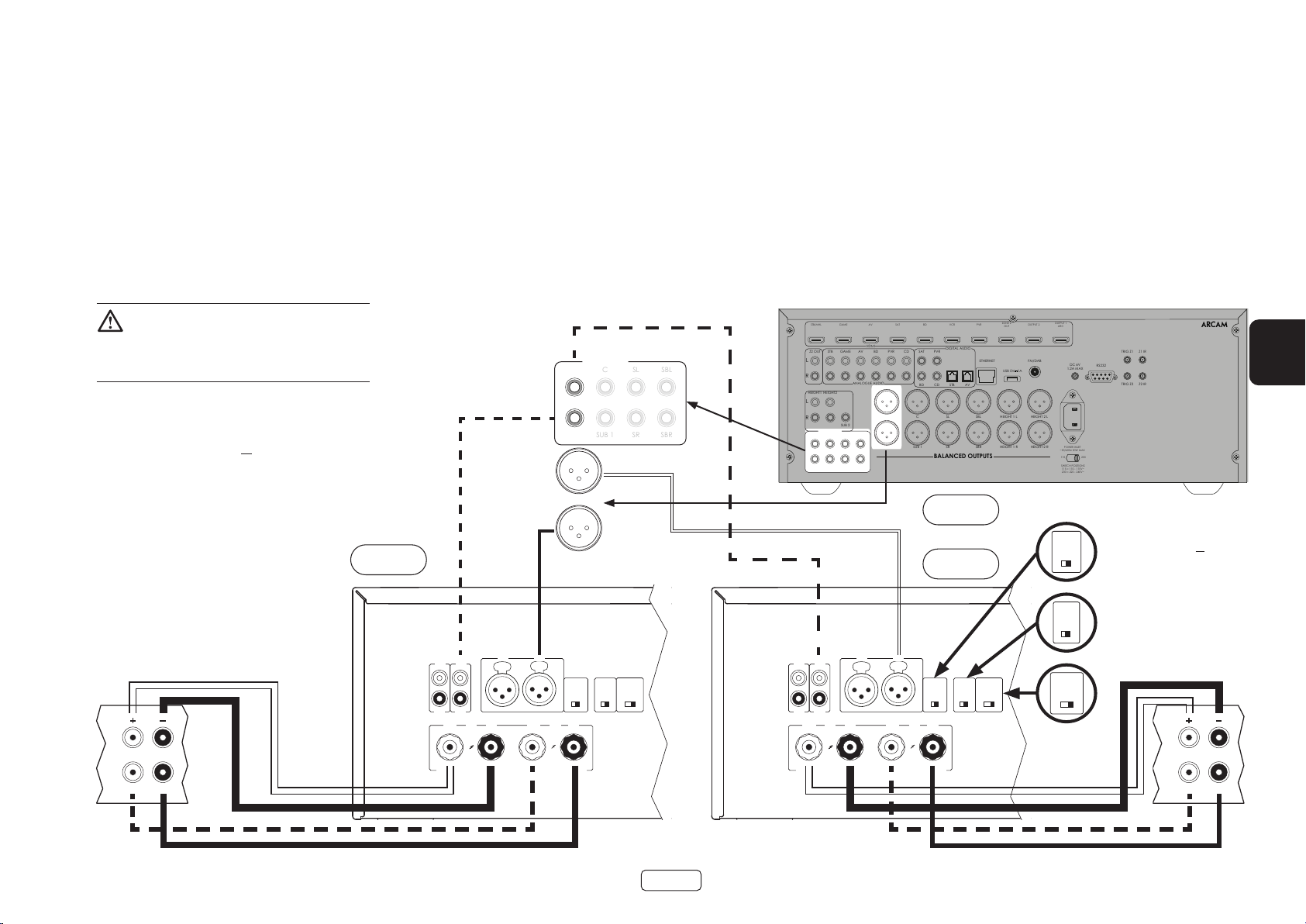
Dual mono / biamp modus - alleen PA240
RCA
XLR
INPUT
+ +
- -
R
ST BRIDGE DM
GAIN
25dB 31dB
MODE
L
INR INL
INR
OUTR
INL
OUTL
RCA
XLR
INPUT
+ +
- -
R
ST BRIDGE DM
GAIN
25dB 31dB
MODE
L
INR INL
INR
OUTR
INL
OUTL
PREAMP OUT
CSLSBL
SUB 1SRSBR
Dual mono vereist het gebruik van een PA240 voor elk
kanaal.
Op een van de PA240’s, sluit de RODE positieve
luidsprekerklem gemarkeerd L+ aan op de positieve
LF klem van uw linker luidspreker. Evenzo, sluit de
ZWARTE negatieve luidsprekerklem gemarkeerd L- aan
op de negatieve LF klem van uw luidspreker.
WAARSCHUWING: Luidsprekers die bi-amping
ondersteunen hebben een metalen strip die de
lage frequentie (LF) en hoge frequentie (HF)
klemmen verbindt. Deze MOETEN worden verwijderd
in een bi-amped systeem
Opmerking: Apparaat dient aangesloten te zijn
via RCA of XLR. Beide afgebeelde versies dienen
slechts ter illustratie.
PA240
Rechts
Gebruik een tweede luidsprekerkabel om de RODE
positieve luidsprekerklem gemarkeerd R+ aan te sluiten
op de positieve HF klem van uw linker luidspreker.
Evenzo, sluit de ZWARTE negatieve luidsprekerklem
gemarkeerd R- aan op de negatieve HF klem van uw
luidspreker.
Herhaal deze stappen voor de rechter luidspreker en
gebruik daarbij dezelfde klemmen op de andere PA240.
FL
FR
FL
FR
Er is in deze opstelling slechts één onderlinge
aansluiting nodig op elke eindversterker en deze
dient te worden aangesloten op de ingang IN L. De
onderlinge verbindingen kunnen of XLR (aanbevolen
voor langere kabels) of phono (RCA) zijn. Stel de INPUTschakelaar op beide van de PA240’s ib op de juiste
instelling voor de gebruikte kabels.
Opmerking: De ingang IN R heeft geen functie in deze
opstelling.
STB/MHL
STB
Z2 OUT
L
R
HEIGHT1 HEIGHT2
L
R
PREAMP OUT
FL C SL SBL
FR SUB 1 SR SBR
GAME
GAME
SUB 2
AV
HDMI
AV
ANALOGUE AUDIO
BD
BD
SAT
PVR
FL C SL SBL HEIGHT 1 L HEIGHT 2 L
FR SUB 1 SR SBR HEIGHT 1 R HEIGHT 2 R
CD
VCR
DIGITAL AUDIO
PVRSAT
BD CD
STB AV
BALANCED OUTPUTS
AV860
PA240
ZONE 2
PVR
OUT
ETHERNET
USB 5V
OUTPUT 1
OUTPUT 2
ARC
FM/DAB
DC 6V
1A
1.2A MAX
POWER INLET
~50/60Hz 50W MAX
115 230
SWITCH POSITIONS
115 = 110 - 115V~
230 = 220 - 240V~
TRIG Z1 Z1 IR
RS232
TRIG Z2 Z2 IR
23425
NL
Opmerking:
Zorg ervoor dat de
25dB 31dB
op ingangstype RCA of XLR
INPUT-schakelaar is ingesteld
GAIN
Zorg ervoor de
GAIN-schakelaar in te stellen
op 31dB
INPUT
XLR
RCA
Zorg ervoor dat de
MODE-schakelaar is ingesteld
op MONO modus, DM
MODE
ST BRIDGE DM
Links
HF
LF
HF
LF
NL-15
Page 80

Probleemoplossing
Probleem Controleer het volgende
Geen geluid De PA720 / PA240 / PA410 eindversterker is correct aangesloten en
ingeschakeld.
Uw audio-/videobron (bijvoorbeeld voorversterker) is correct
aangesloten.
De PA720 / PA240 / PA410 is niet in beveiligingsmodus, zoals
beschreven in de volgende paragraaf.
De PA720, PA240 and PA410 is niet gedempt.
Het geluid onderbreekt onverwacht De PA720 / PA240 / PA410 kan een beveiligingsmodus openen,
afhankelijk van de waargenomen storing. De LED op het voorpaneel zal
het storingstype aangeven, volgens de lijst hieronder
KNIPPEREND WIT: De interne temperatuur van het apparaat heeft een
onveilig niveau bereikt. Laat de PA720 / PA240 / PA410 afkoelen.
KNIPPEREND ROOD: De PA720 / PA240 / PA410 versterker heeft
een luidsprekerkortsluiting waargenomen. Mocht dit het geval
zijn, inspecteer a.u.b. alle luidsprekerkabels om te verifiëren dat
geen van hen samen zijn kortgesloten. Deze storing komt vaak
voor wanneer blootliggende draden worden gebruikt om de
luidsprekeraansluitingen tot stand te brengen.
KNIPPEREND ORANJE: Alleen PA720 en PA240. De versterker heeft een
voedingsafwijking waargenomen.
Na een van de bovengenoemde storingen, zal de versterker zichzelf
uitschakelen en wordt de voeding richting te luidsprekers onderbroken.
Om de PA720 / PA240 / PA410 te blijven gebruiken, moet de storing
worden verholpen en moet het apparaat UIT en vervolgens IN worden
geschakeld.
NL-16
Page 81

Specicaties
PA720
Continue vermogensuitgang @ 0.2% THD, per kanaal
Zeven kanalen aangedreven, 4 Ω/8 Ω, 1 kHz 140W / 100W
Vier kanalen aangedreven, 4 Ω/8 Ω, 1 kHz 175W / 110W
Twee kanalen aangedreven, 4 Ω/8 Ω, 1 kHz 225W / 140W
Harmonische vervorming, 80%
vermogen, 8 Ω op 1 kHz
Ingangen
Ingangsgevoeligheid 100 W/8 Ω 800mV RMS 1.6V RMS
Signaal-/ruisverhouding (A-wtd) 100 W/8 Ω 112dB
Ingangsimpedantie 10kΩ
Frequentiebereik 20 - 20kHz +/-0.05dB
Algemeen
Netspanning 110–120V or 220–240V, 50–60Hz
Maximaal stroomverbruik 1.5kW
Laag stroomverbruik in stand-by 0.5W
Netwerk stand-by verbruik 2W
Afmetingen B x H x D (inclusief voetstukken,
bedieningsknop en luidsprekerklemmen)
Gewicht (netto) 18kg
Gewicht (bruto) 19.7kg
0,002%
RCA-type XLR-type
433 x 425 x 177mm
NL
De waarden van alle specicaties zijn typisch, tenzij
anders vermeld. Arcam hanteert een beleid voor
onafgebroken verbetering van haar producten.
Dit betekent dat ontwerpen en specicaties zonder
voorafgaande kennisgeving kunnen worden
veranderd. Fouten en weglatingen uitgesloten.
NL-17
Page 82

PA240
Continue vermogensuitgang @ 0.2% THD, per kanaal
Twee kanalen aangedreven, 4 Ω/8 Ω, 1 kHz 380W / 225W
Eén kanaal aangedreven,
8 Ω bridged modus, 1 kHz
Harmonische vervorming, 80%
vermogen, 8 Ω op 1 kHz
Ingangen
Ingangsgevoeligheid 200 W/8 Ω 1.15V RMS 2.3V RMS 2.3V RMS 4.6V RMS
Signaal-/ruisverhouding (A-wtd) 100 W/8 Ω 110dB 114dB 110dB 114dB
Ingangsimpedantie 10kΩ
Frequentiebereik 20 - 20kHz +/-0.05dB
Algemeen
Netspanning 110–120V or 220–240V, 50–60Hz
Maximaal stroomverbruik 1.5kW
Laag stroomverbruik in stand-by 0.5W
Netwerk stand-by verbruik 2W
Afmetingen B x H x D (inclusief voetstukken,
bedieningsknop en luidsprekerklemmen)
Gewicht (netto) 18kg
Gewicht (bruto) 19.7kg
790W
0.001%
RCA-type XLR-type
31dB 25dB 31dB 25dB
433 x 425 x 177mm
De waarden van alle specicaties zijn typisch, tenzij
anders vermeld. Arcam hanteert een beleid voor
onafgebroken verbetering van haar producten.
Dit betekent dat ontwerpen en specicaties zonder
voorafgaande kennisgeving kunnen worden
veranderd. Fouten en weglatingen uitgesloten.
NL-18
Page 83

PA410
Continue vermogensuitgang @ 0.2% THD, per kanaal
Vier kanalen aangedreven, 4 Ω/8 Ω, 1 kHz 70W / 50W
Twee kanalen aangedreven, 4 Ω/8 Ω, 1 kHz 90W / 60W
Harmonische vervorming, 80%
vermogen, 8 Ω op 1 kHz
Ingangsgevoeligheid 50 W/8 Ω 560mV RMS
Signaal-/ruisverhouding (A-wtd) 50 W/8 Ω 106dB
Ingangsimpedantie 10kΩ
Frequentiebereik 20 - 20kHz +/-0.2dB
Algemeen
Netspanning 110–120V or 220–240V, 50–60Hz
Maximaal stroomverbruik 700W
Laag stroomverbruik in stand-by 0.5W
Netwerk stand-by verbruik 2W
Afmetingen B x H x D (inclusief voetstukken,
bedieningsknop en luidsprekerklemmen)
Gewicht (netto) 10kg
Gewicht (bruto) 11.5kg
0.003%
433x325x105mm
NL
De waarden van alle specicaties zijn typisch, tenzij
anders vermeld. Arcam hanteert een beleid voor
onafgebroken verbetering van haar producten.
Dit betekent dat ontwerpen en specicaties zonder
voorafgaande kennisgeving kunnen worden
veranderd. Fouten en weglatingen uitgesloten.
NL-19
Page 84

Wereldwijde garantie
Dit geeft u recht op kosteloze reparatie van het apparaat gedurende de eerste vijf jaar na aankoop, op voorwaarde
dat het oorspronkelijk was aangeschaft bij een geautoriseerde Arcam-dealer. De Arcam-dealer is verantwoordelijk
voor alle naverkoopservice. De fabrikant kan niet aansprakelijk worden gesteld voor gebreken als gevolg van
ongeval, verkeerd gebruik, misbruik, slijtage, verwaarlozing of door ongeoorloofde aanpassing en/of reparatie, noch
kan de fabrikant aansprakelijk worden gesteld voor schade of verlies ontstaan tijdens het transport van of naar de
persoon die een garantieclaim indient.
De garantie dekt:
Onderdelen (exclusief diskdrives) en arbeidskosten voor 5 jaar vanaf de aankoopdatum (zie hieronder voor meer
algemene voorwaarden). U moet na vijf jaar voor zowel onderdelen als arbeidskosten betalen.
De garantie dekt diskdrives (van elke soort) voor twee jaar vanaf de aankoopdatum.
De garantie dekt op geen enkel moment batterijvervangingen.
De garantie dekt op geen enkel moment transportkosten.
Garantieclaims
Deze apparatuur moet worden verpakt in de originele verpakking en naar de dealer worden geretourneerd van wie
het werd gekocht. Het moet franco vervoer via een gerenommeerde vervoerder worden toegezonden – niet per
post. Er kan tijdens transport naar de dealer of distributeur geen verantwoordelijkheid voor het apparaat worden
aanvaard en klanten worden daarom geadviseerd om het apparaat te verzekeren tegen verlies of beschadiging
tijdens transport.
Neem voor meer informatie contact op met Arcam via arcam.support@harman.co.uk.
Problemen?
Als uw Arcam-dealer geen enkele vraag met betrekking tot dit of enig ander Arcam-product kan beantwoorden,
neem contact op met Arcam Customer Support op het hierboven vermelde adres en we zullen ons best doen om
u te helpen.
Online registratie
U kunt uw product online registreren op www.arcam.co.uk.
NL-20
Page 85

AMPLIFICADOR DE POTENCIA
MANUAL
ES
PA720 / PA240 / PA410
Page 86

Bienvenido
Gracias y felicidades...
... por comprar su PA720, PA240 or PA410 amplificador de potencia Arcam.
Arcam ha producido productos especializados de audio de calidad excepcional por más de cuatro décadas y los
nuevos PA720, PA240 and PA410 amplificadores de potencia son los más recientes en una larga línea de dispositivos
Hi-Fi galardonados. El diseño del rango HDA hace uso de toda la experiencia de Arcam como una de las compañías
de audio más respetadas del R.U., para producir el mejor rango de desempeño de amplificadores de potencia
multicanales de Arcam a la fecha: diseñados y ensamblados para darle a sus oídos años de gozo auditivo.
Este manual es una guía para instalar y usar el PA720, PA240 and PA410 e incluye información sobre las funciones
más avanzadas. Use la lista de contenido en la página siguiente para consultar la sección de interés.
Esperamos que su producto le dé años de operación libre de problemas. En el caso poco probable de darse algún fallo, o
simplemente si requiere más información sobre los productos Arcam, nuestra red de distribuidores estará encantada de
ayudarle. También se puede encontrar información adicional en el sitio Web de Arcam www.arcam.co.uk.
El equipo de desarrollo de PA720, PA240 and PA410
ES-2
Page 87

Índice
Bienvenido ES-2
Descripción general ES-4
Colocación de la unidad ES-4
Cables de interconexión ES-4
Alimentación ES-4
Controles y conexiones del panel trasero PA720 ES-5
Controles y conexiones del panel trasero PA240 ES-6
Controles y conexiones del panel trasero PA410 ES-7
Conexiones del sistema de control ES-8
Red y RS232 ES-8
USB ES-8
ENTRADA/SALIDA de disparador ES-8
Conexiones y controles del panel frontal ES-9
Funcionamiento ES-10
Encendido ES-10
Modo de espera automático ES-10
Red y RS322 en espera ES-10
Silenciar la salida ES-10
Interruptores de modo ES-10
Conectar las fuentes y altavoces ES-11
Modo mono puente - PA240 únicamente ES-14
Modo mono dual / biamplificado - PA240 únicamente ES-15
Resolución de problemas ES-16
Especicaciones ES-17
PA720 ES-17
PA240 ES-18
PA410 ES-19
Garantía Mundial ES-20
ES
ES-3
Page 88

Descripción general
Amplicadores
PA720, PA240 and PA410 de
Arcam
Los amplificadores PA720, PA240 and PA410 de Arcam
brindan una calidad de sonido líder en su sector para la
mejor reproducción de su música.
Aprovechando los muchos años de experiencia en
diseño de amplificadores en Arcam, estos productos
usan componentes de la mejor calidad y experiencia
en ingeniería para producir amplificadores que le darán
muchos años de placer musical y servicio confiable.
Con una fuente de alimentación toroidal, chasis con
amortiguador acústico, tecnología clase G (PA240
& PA720), etapas de salida de transistor paralelo
(PA240) y niveles excepcionalmente bajos de ruido y
distorsión, los amplificadores PA720, PA240 and PA410
son completamente capaces de reproducir música
con toda su autoridad original y a detalle. Puede estar
seguro de que escuchará la música exactamente como
quiso el artista.
Los amplificadores PA720, PA240 and PA410 están
diseñados para producir un nivel de desempeño que
realmente dará vida a su música.
Colocación de la unidad
Coloque el amplificador sobre una superficie plana y
firme, evitando la luz directa del sol y las fuentes de
calor o humedad.
No coloque el PA720, PA240 or PA410 sobre un
amplificador de potencia u otra fuente de calor.
No coloque el amplificador en un espacio cerrado,
como en un librero o en un gabinete cerrado,
a menos que tenga una buena ventilación. Los
PA720, PA240 and PA410 están diseñados para
calentarse durante la operación normal.
No coloque ningún otro equipo o elemento sobre
el amplificador ya que obstaculizaría el flujo de aire
alrededor del disipador térmico, provocando el
sobrecalentamiento del amplificador. (La unidad
colocada sobre el amplificador también se calentaría.)
PA720
No coloque su tocadiscos sobre la unidad. Los
tocadiscos son muy sensibles al ruido que genera
la alimentación principal, y se puede oír como un
"zumbido" de fondo si el tocadiscos está demasiado
cerca.
El funcionamiento normal de la unidad puede
interrumpirse por interferencias electromagnéticas
fuertes. Si esto ocurre, simplemente reinicie la unidad
con el botón de encendido, o mueva la unidad hacia
otra ubicación.
Cables de interconexión
Recomendamos que utilice cables blindados de
alta calidad que hayan sido diseñados para esta
aplicación en particular. Otros cables tendrán diferentes
características de impedancia, lo que degradará el
rendimiento de su sistema (por ejemplo, no utilice
cableado diseñado para video, para transmitir señales
de audio). Todos los cables deben mantenerse lo más
cortos como sea posible en la práctica.
Es recomendable, cuando conecte su equipo,
asegurarse de que el cableado de alimentación se
mantenga lo más alejado posible de los cables de
audio. No hacerlo puede causar ruidos indeseados en
las señales de audio.
POWER AMPLIFIER
POWER
STANDBYMUTE
Alimentación
El amplificador se entrega con un cable de alimentación
con enchufe. Compruebe que el conector que se
incluye encaje con su tomacorriente; si necesitase
un nuevo conector de alimentación, contacte a su
distribuidor de Arcam.
Si su voltaje de alimentación o enchufe de alimentación
es diferente, contacte inmediatamente con su
distribuidor de Arcam.
Empuje la clavija IEC del cable de alimentación dentro
del receptáculo en la parte trasera del amplificador,
cerciorándose de que está completamente introducida.
Conecte el otro extremo del cable en el tomacorriente
y, si fuera necesario, enciéndalo.
ES-4
Page 89

Controles y conexiones del panel trasero PA720
ENTRADAS DE AUDIO XLR
BALANCEADAS
Conecte las salidas XLR a su preamplificador.
Consulte “Conectar las fuentes y altavoces” en
página ES-11.
IN7
IN6
IN5
IN4
IN3
OUT7
OUT6
OUT5
OUT4
OUT3
IN2
OUT2
IN1
OUT1
INTERRUPTORES DE ENTRADA
Permiten que el PA720 se configure
en diferentes tipos de entrada
Consulte “Conectar las fuentes y
Solo para actualizaciones de
software. Consulte “USB” en
altavoces” en página ES-11.
IN7 IN6 IN5 IN4 IN3 IN2 IN1
CH5CH6CH7
CH4 CH3 CH2 CH1
4-16 OHMSCLASS 2 WIRING
USB
página ES-8.
Trigger IN permite que una fuente externa apague o encienda el PA720.
Trigger OUT permite que el PA720 controle el estado de alimentación de
ENTRADA/SALIDA DEL DISPARADOR
otro equipo conectado
Consulte “ENTRADA/SALIDA de disparador” en página ES-8.
TRIGGER IN
USB
5V
100mA
TRIGGER OUT
(12V 100mA)
SWITCH POSITIONS
115 = 110 - 120V ~
230 = 220 - 240V ~
RCA
INPUT
XLR
RS232 NET
POWER INLET
110-120V/220-240V~
50/60Hz 1.5kW MAX
SUPPLY
VOLTAGE
ES
ENTRADAS DEL PREAMPLIFICADOR
Conectar las salidas fono de su
preamplificador.
Consulte “Conectar las fuentes y
altavoces” en página ES-11.
SALIDA DEL PREAMPLIFICADOR
OUT1-OUT7 brinda una copia de
la señal aplicada solo a conectores
fono IN1-IN7, no al XLR.
Nota: Esta es una salida pasiva,
no se aplica ningún filtrado
o amplificación adicional.
TERMINALES DEL
ALTAVOZ
Consulte “Conectar las
fuentes y altavoces” en
página ES-11.
Esta conexión permite el control remoto
RS232
desde un sistema de automatización
doméstico de terceros o una computadora.
Consulte “Red y RS232” en página ES-8.
Esta conexión permite el control remoto desde
RED
un sistema de automatización doméstico de
terceros o una computadora.
Consulte “Red y RS232” en página ES-8.
ES-5
ENTRADA DE ALIMENTACIÓN
Conecte aquí el cable de
alimentación correcto.
¡Por favor lea las secciones “Colocación de la
unidad”, “Alimentación” y “Cables de
interconexión” en el Página ES-4 antes de
conectar su amplicador PA720!
SELECCIÓN DE VOLTAJE
Asegúrese de que el voltaje
seleccionado sea igual a la
alimentación local.
Page 90

Controles y conexiones del panel trasero PA240
RS232 NET
TRIGGER OUT
(12V 100mA)
TRIGGER IN
POWER INLET
110-120V/220-240V~
50/60Hz 1.5kW MAX
USB
5V
100mA
SWITCH POSITIONS
115 = 110 - 120V ~
230 = 220 - 240V ~
SUPPLY
VOLTAGE
RCA
XLR
INPUT
+
4-16 OHMS. CLASS 2 WIRING
+
- -
R
ST BRIDGE DM
GAIN
25dB 31dB
MODE
L
INR INL
INR
OUTR
INL
OUTL
ENTRADAS DE AUDIO XLR
BALANCEADAS
Conecte las salidas XLR a su preamplificador.
Consulte “Conectar las fuentes y altavoces”
en página ES-11.
INTERRUPTORES DE ENTRADA
Permiten que el PA240 se configure
en diferentes modos operativos.
Consulte “Conectar las fuentes y
altavoces” en página ES-11.
Solo para actualizaciones de
USB
software. Consulte “USB” en
página ES-8.
Trigger IN permite que una fuente externa apague o encienda el PA240.
ENTRADA/SALIDA DEL DISPARADOR
Trigger OUT permite que el PA240 controle el estado de alimentación de
otro equipo conectado
Consulte “ENTRADA/SALIDA de disparador” en página ES-8.
ENTRADAS DEL PREAMPLIFICADOR
Conectar las salidas fono de su
preamplificador.
Consulte “Conectar las fuentes y
altavoces” en página ES-11.
SALIDA DEL PREAMPLIFICADOR
OUTL y OUTR brindan una
copia de la señal aplicada
solo a los conectores fono
IN L e IN R, no al XLR.
Nota: Esta es una salida pasiva,
no se aplica ningún filtrado
o amplificación adicional.
TERMINALES DEL
ALTAVOZ
Esta conexión permite el control remoto
Consulte “Conectar las
fuentes y altavoces” en
página ES-11.
doméstico de terceros o una computadora.
RS232
desde un sistema de automatización
Consulte “Red y RS232” en página ES-8.
RED
Esta conexión permite el control remoto desde
un sistema de automatización doméstico de
terceros o una computadora.
Consulte “Red y RS232” en página ES-8.
ES-6
ENTRADA DE ALIMENTACIÓN
Conecte aquí el cable de
alimentación correcto.
¡Por favor lea las secciones “Colocación de la
unidad”, “Alimentación” y “Cables de
interconexión” en el Página ES-4 antes de
conectar su amplicador PA240!
SELECCIÓN DE VOLTAJE
Asegúrese de que el voltaje
seleccionado sea igual a la
alimentación local.
Page 91

POWER INLET
110-120V/220-240V ~ 50/60Hz
500W MAX
SUPPLY
VOLTAGE
SWITCH POSITIONS
115 = 110 - 120V ~
230 = 220 - 240V ~
RS232NET USB
5V 100mA
CH1
4-16 OHMS
CLASS 2 WIRING
CH2CH3CH4
IN4
OUT4
IN3
OUT3
IN2
OUT2
IN1
OUT1
TRIGGER OUT
(12V 100mA)
TRIGGER IN
Controles y conexiones del panel trasero PA410
ENTRADA DE ALIMENTACIÓN
SELECCIÓN DE VOLTAJE
Asegúrese de que el voltaje
seleccionado sea igual a la
Conecte aquí el cable de
alimentación correcto.
Esta conexión permite el control remoto
desde un sistema de automatización
doméstico de terceros o una computadora.
alimentación local.
Consulte “Red y RS232” en página ES-8.
RED
Conecte su red alámbrica local a un puerto. El
segundo puerto puede usarse para conectarse a
otros dispositivos
Consulte “Red y RS232” en página ES-8.
RS232
Solo para actualizaciones de
USB
software. Consulte “USB” en
página ES-8.
ENTRADAS DEL PREAMPLIFICADOR
Conectar las salidas fono de su
preamplificador.
Consulte “Conectar las fuentes y
altavoces” en página ES-11.
SALIDA DEL PREAMPLIFICADOR
OUT1 a OUT4 brindan una
copia de la señal aplicada a los
conectores fono IN1 a IN4.
Nota: Esta es una salida pasiva,
no se aplica ningún filtrado o
amplificación adicional.
ES-7
Trigger IN permite que una fuente externa apague o encienda el PA410.
ENTRADA/SALIDA DEL DISPARADOR
Trigger OUT permite que el PA410 controle el estado de alimentación de
otro equipo conectado
Consulte “ENTRADA/SALIDA de disparador” en página ES-8.
TERMINALES DEL
ALTAVOZ
Consulte “Conectar las
fuentes y altavoces” en
página ES-11.
¡Por favor lea las secciones “Colocación de la
unidad”, “Alimentación” y “Cables de
interconexión” en el Página ES-4 antes de
conectar su amplicador PA410!
ES
Page 92

RS232 NET
TRIGGER OUT
(12V 100mA)
TRIGGER IN
POWER INLET
110-120V/220-240V~
50/60Hz 1.5kW MAX
USB
5V
100mA
SWITCH POSITIONS
115 = 110 - 120V ~
230 = 220 - 240V ~
SUPPLY
VOLTAGE
RCA
XLR
INPUT
IN7
OUT7
IN6
OUT6
IN5
OUT5
IN4
OUT4
IN3
OUT3
IN2
OUT2
IN1
OUT1
IN7 IN6 IN5 IN4 IN3 IN2 IN1
CH4 CH3 CH2 CH1
4-16 OHMSCLASS 2 WIRING
CH5CH6CH7
Conexiones del sistema de
control
Red y RS232
El PA720, PA240 and PA410 cuenta con una red y puerto
RS232 que pueden usarse para conectarse a una red
local, computadora o sistema de automatización del
hogar, de forma que el amplificador se puede controlar
y monitorear remotamente.
Varios sistemas de terceros están disponibles y brindan
un sofisticado control de todos sus dispositivos
de entretenimiento. Póngase en contacto con su
distribuidor o instalador para más detalles.
Para detalles técnicos de protocolos de control, por
favor consulte el PA720 / PA240 / PA410 documento
de control RS232/IP, disponible para descarga en www.
arcam.co.uk, para más información.
Nota: De forma predeterminada, el control de red y
RS232 se desactiva durante el modo de espera para
minimizar el consumo de energía durante la espera.
Para activar el control de red, vea “Red y RS322 en
espera” en página ES-10.
GAME
STB/MHL
STB
GAME
Z2 OUT
L
R
HEIGHT1 HEIGHT2
L
R
SUB 2
PREAMP OUT
FL C SL SBL
FR SUB 1 SR SBR
Enrutador de red
AV
HDMI
AV
ANALOGUE AUDIO
BD
BD
SAT
PVR
FL C SL SBL HEIGHT 1 L HEIGHT 2 L
FR SUB 1 SR SBR HEIGHT 1 R HEIGHT 2 R
CD
BD CD
VCR
DIGITAL AUDIO
PVRSAT
STB AV
BALANCED OUTPUTS
1 2 3 4NET
PVR
ETHERNET
ZONE 2
OUT
USB 5V
OUTPUT 1
OUTPUT 2
ARC
FM/DAB
DC 6V
1A
1.2A MAX
POWER INLET
~50/60Hz 50W MAX
115 230
SWITCH POSITIONS
115 = 110 - 115V~
230 = 220 - 240V~
TRIG Z1 Z1 IR
RS232
TRIG Z2 Z2 IR
23425
AV860
Controlador de automatización casero
RS232
USB
El puerto USB se usa exclusivamente para
actualizaciones de software. Para la versión de software
más reciente así como para obtener más información,
visite www.arcam.co.uk.
ENTRADA/SALIDA de disparador
El estado de energía del PA720, PA240 and PA410 puede
controlarse mediante fuentes de audio/video (como
Arcam AVR). En este caso, conecte el TRIGGER OUT
de la fuente al TRIGGER IN del PA720, PA240 or PA410
utilizando un conector mono de 3.5 mm.
De forma similar, el PA720, PA240 and PA410 puede
controlar el estado de alimentación del producto
compatible (como otro PA720, PA240 or PA410). En este
caso, conecte el TRIGGER IN de la fuente al TRIGGER
OUT del PA720, PA240 or PA410 utilizando un conector
mono de 3,5 mm.
Nota: No se incluyen los conectores.
NET
Controlador de automatización casero
POWER INLET
110-120V/220-240V ~ 50/60Hz
500W MAX
SUPPLY
VOLTAGE
SWITCH POSITIONS
115 = 110 - 120V ~
230 = 220 - 240V ~
RS232NET USB
5V 100mA
TRIGGER IN
TRIGGER OUT
(12V 100mA)
PA720
IN4
IN3
OUT4
OUT3
ES-8
CH2CH3CH4
CH1
IN2
IN1
OUT2
OUT1
CLASS 2 WIRING
4-16 OHMS
PA410
Page 93
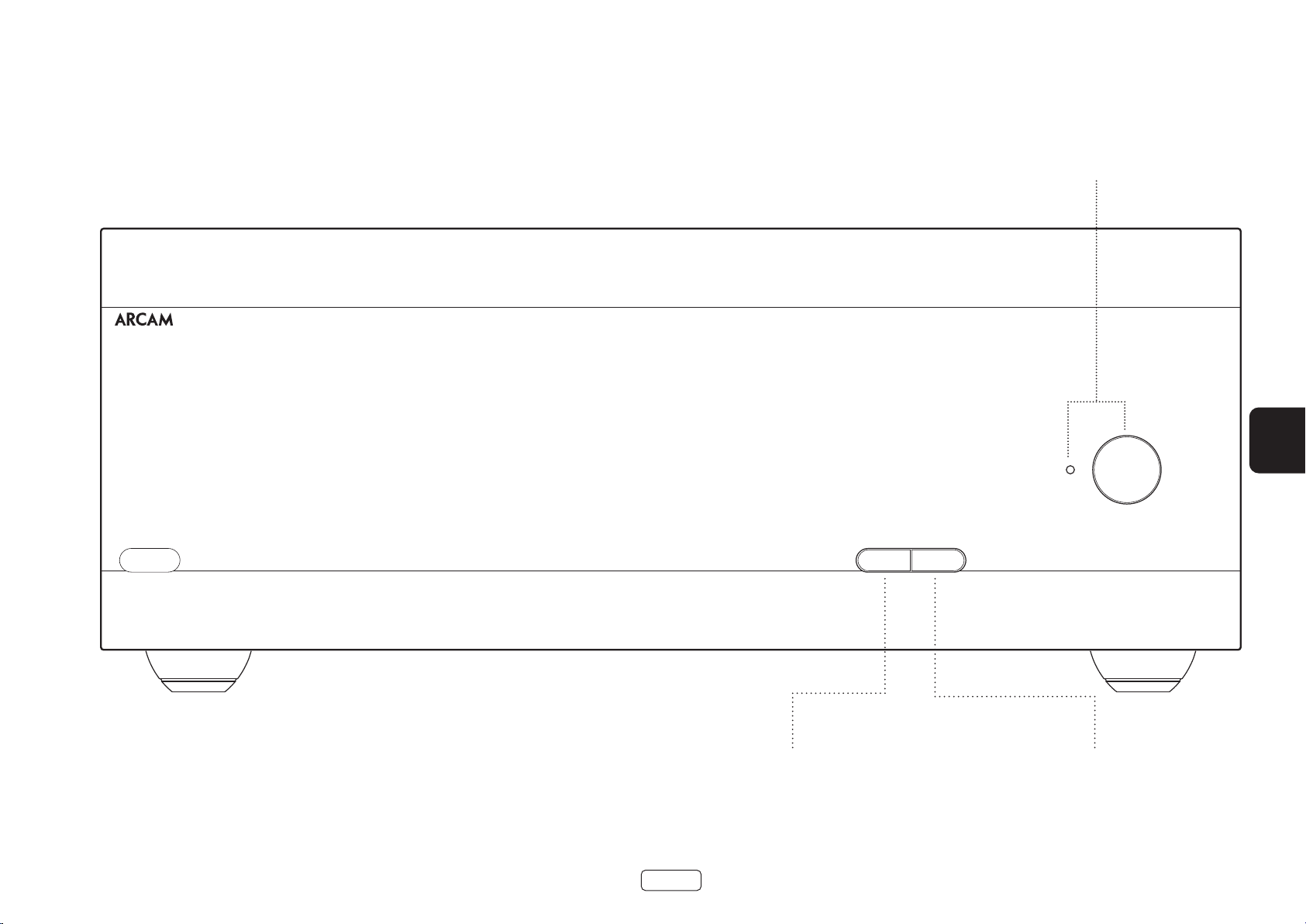
Conexiones y controles del panel frontal
PA720
INDICADOR E INTERRUPTOR DE
ENCENDIDO
Consulte “Encendido” en página ES-10.
POWER AMPLIFIER
ES
POWER
STANDBYMUTE
Silencia/activa las PA720, PA240 or PA410 salidas
SILENCIAR
de los altavoces.
Consulte “Silenciar la salida” en página ES-10.
ES-9
UNIDAD EN ESPERA
Consulte “Encendido” en página ES-10.
Page 94

Funcionamiento
Encendido
El botón POWER enciende y apaga la unidad. El LED
indicador de estado señala el estado del amplificador:
cambia de rojo a naranja y luego a blanco si la
alimentación principal está conectada y la unidad está
encendida.
Presionar el botón STBY mientras la unidad está
encendida colocará el PA720, PA240 or PA410 en modo
de espera. Presione el botón STBY nuevamente para
sacar la unidad del modo de espera.
Modo de espera automático
Para cumplir con las regulaciones internacionales de
productos de consumo, esta unidad se encuentra
diseñada para ingresar al modo de espera si no se
detectan interacciones del usuario o señales de
entrada de audio por un tiempo prolongado (el valor
predeterminado es 20 minutos). La unidad puede salir
del modo de espera presionando el botón STBY en
el panel frontal, la entrada del disparador o RS232 o
comando ethernet (si se encuentra activado, vea “Red y
RS322 en espera” para más información)
El tiempo de espera puede ajustarse utilizando RS232
o los comandos del control IP. Por favor consulte
PA720 / PA240 / PA410 el documento de control RS232/IP,
disponible para descarga enwww.arcam.co.uk.
Alternativamente, presionar y mantener presionado el
botón MUTE alternará el tiempo de espera entre OFF y 20
minutos.
El LED parpadeará para indicar el cambio de configuración,
rojo para APAGADO, verde durante 20 minutos.
Nota: Si el tiempo límite de espera está en APAGADO, se
desactivará la función de espera.
Red y RS322 en espera
En modo de espera con poca energía, la red y la
funcionalidad RS322 están desactivadas.
Para activar la red y RS232 en modo de espera, envíe un
comando de control o solicitud de estado a la unidad
mientras esté encendida.
Esto activará cualquiera que sea el método de control
utilizado cuando la unidad está en espera.
Nota: Para indicar que la unidad no está en modo de
espera con poca energía, el LED parpadeará brevemente
al entrar al modo de espera.
Nota: Activar la red o control RS232 incrementará el
consumo de energía de espera. Para restaurar la unidad
al consumo de modo de espera con baja energía
predeterminado, mantenga oprimido el botón STBY
por más de 3 segundos o restaure la unidad a los valores
de fábrica.
Silenciar la salida
Las salidas de los altavoces del PA720, PA240 or PA410
se pueden silenciar presionando el botón MUTE en
el panel delantero o enviando el comando pertinente
mediante el RS232 o la conexión de red.
Si se silencia la unidad, el indicador de energía del panel
frontal cambiará a naranja.
Para cancelar el silencio, presione nuevamente el botón
MUTE o envíe el comando pertinente mediante el
RS232 o la conexión de red.
Interruptores de modo
Los diversos interruptores de modo ubicados en la
parte trasera de los amplificadores PA720 y PA240 le
permitirán configurar su amplificador de potencia a los
valores específicos de su equipo. Consulte “Conectar las
fuentes y altavoces” en página ES-11 para obtener más
información.
INPUT (PA720 y PA240 únicamente)
Este interruptor selecciona entre el XLR y las entradas
fono RCA del amplificador. Seleccione cualquier
método de conexión que esté usando para conectar su
preamplificador.
GAIN(PA240 únicamente)
Este interruptor permite cambiar la ganancia de
Arcam estándar de 31 dB (que es igual a todos los
amplificadores y receptores Arcam) a 26 dB. Esto permite
la flexibilidad de conectar múltiples amplificadores
PA240 en diferentes modos a múltiples altavoces.
En configuraciones normales, este interruptor debe
estar a la izquierda en 31 dB.
MODE (PA240 únicamente)
Este interruptor selecciona los diferentes modos de
amplificación del PA240.
STEREO (ST)
Este es el modo de amplificación estéreo estándar que
utiliza dos entradas de preamplificador separadas que
controlan dos salidas de altavoz separadas.
DUAL MONO (DM)
Este modo permite que dos altavoces separados se
controlen desde una sola entrada de preamplificador.
Alternativamente, los dos controladores de un solo
altavoz pueden ser biamplificados desde un solo PA240.
ES-10
BRIDGED MONO (BRIDGE)
Este modo utiliza ambos canales del PA240 para
controlar un solo altavoz. Esta es la versión definitiva de
la amplificación de alta potencia y alta fidelidad.
Page 95
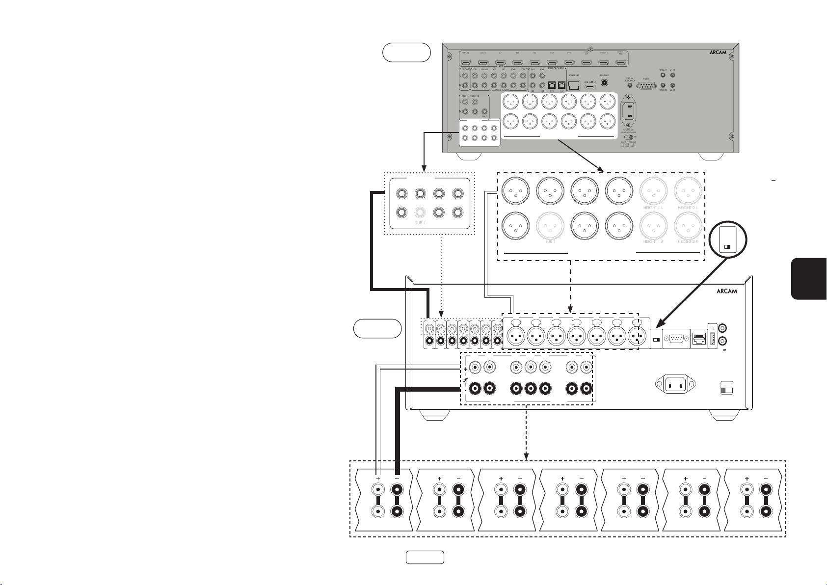
Conectar las fuentes y altavoces
RS232 NET
TRIGGER OUT
(12V 100mA)
TRIGGER IN
POWER INLET
110-120V/220-240V~
50/60Hz 1.5kW MAX
USB
5V
100mA
SWITCH POSITIONS
115 = 110 - 120V ~
230 = 220 - 240V ~
SUPPLY
VOLTAGE
RCA
XLR
INPUT
IN7
OUT7
IN6
OUT6
IN5
OUT5
IN4
OUT4
IN3
OUT3
IN2
OUT2
IN1
OUT1
IN7 IN6 IN5 IN4 IN3 IN2 IN1
CH4 CH3 CH2 CH1
4-16 OHMSCLASS 2 WIRING
CH5CH6CH7
PREAMP OUT
SUB 1
HEIGHT 1 L
HEIGHT 2 L
SUB 1
HEIGHT 1 R
HEIGHT 2 R
PA720
Conecte el terminal de altavoz positivo ROJO
denominado CH1 a CH7+ al terminal positivo de su
altavoz. De manera similar, conecte el terminal de
altavoz negativo NEGRO del mismo canal al terminal
negativo de su altavoz.
Repita este proceso para los otros altavoces y utilice la
misma entrada y terminales de altavoz respectivos para
cada canal.
NOTA: Todos los canales son idénticos, así que no hay
requisitos de conectar canales de salida AVR específicos
a canales de amplificador específicos.
AV860
FL C SL SBL
FR
SR SBR
STB/MHL
STB
Z2 OUT
L
R
HEIGHT1 HEIGHT2
L
R
PREAMP OUT
FL C SL SBL
FR SUB 1 SR SBR
GAME
GAME
SUB 2
AV
HDMI
AV
ANALOGUE AUDIO
BD
BD
SAT
CD
PVR
PVRSAT
BD CD
FL C SL SBL HEIGHT 1 L HEIGHT 2 L
FR SUB 1 SR SBR HEIGHT 1 R HEIGHT 2 R
BALANCED OUTPUTS
FL C SL SBL
FR
VCR
DIGITAL AUDIO
STB AV
OUT
ETHERNET
USB 5V
SR SBR
ZONE 2
PVR
BALANCED OUTPUTS
OUTPUT 1
OUTPUT 2
ARC
FM/DAB
DC 6V
1A
1.2A MAX
POWER INLET
~50/60Hz 50W MAX
115 230
SWITCH POSITIONS
115 = 110 - 115V~
230 = 220 - 240V~
TRIG Z1 Z1 IR
RS232
TRIG Z2 Z2 IR
23425
Nota: La unidad debe
conectarse vía RCA o
XLR. Ambas versiones
mostradas con fines
ilustrativos únicamente.
INPUT
XLR
RCA
ES
Nota: Canal único mostrado por
claridad
Notas sobre la realización de conexiones de altavoces
No realice las conexiones al amplificador mientras lo tenga encendido. Le recomendamos
que tenga el amplificador completamente desconectado de la red eléctrica antes de
empezar.
Antes de encender su(s) amplificador(es) por primera vez después de conectarlo(s) a
los altavoces, compruebe minuciosamente todas las conexiones. Cerciórese de que
los cables o alambres sin aislamiento (pelados) no se tocan entre si, ni a la carcasa del
amplificador (ya que podrían generar cortocircuitos), y que tiene conectado el positivo
(+) al positivo y el negativo (–) al negativo. No olvide comprobar el cableado tanto del
amplificador como del altavoz.
Tras realizar conexiones: encienda el amplificador e incremente gradualmente el
volumen al nivel de escucha requerido.
Si no está seguro de cómo debe conectarse su sistema, póngase en contacto con su
distribuidor Arcam quien estará complacido de poder ayudarle.
PA720
HF
LF
HF
LF
ES-11
HF
LF
HF
LF
HF
LF
HF
LF
HF
LF
Page 96

PA240
RCA
XLR
INPUT
+
4-16 OHMS. CLASS 2 WIRING
+
- -
R
ST BRIDGE DM
GAIN
25dB 31dB
MODE
L
INR INL
INR
OUTR
INL
OUTL
PREAMP OUT
CSLSBL
SUB 1SRSBR
Conecte el terminal de altavoz positivo ROJO
denominado L+ al terminal positivo de su altavoz. De
manera similar, conecte el terminal de altavoz negativo
NEGRO denominado L al terminal negativo de su
altavoz.
Repita este proceso para el altavoz derecho.
Nota: La unidad debe conectarse vía RCA o
XLR. Ambas versiones mostradas con fines
ilustrativos únicamente.
FL
FR
STB/MHL
STB
Z2 OUT
L
R
HEIGHT1 HEIGHT2
L
R
PREAMP OUT
FL C SL SBL
FR SUB 1 SR SBR
GAME
GAME
SUB 2
AV
HDMI
AV
ANALOGUE AUDIO
BD
BD
SAT
CD
PVR
PVRSAT
BD CD
FL C SL SBL HEIGHT 1 L HEIGHT 2 L
FR SUB 1 SR SBR HEIGHT 1 R HEIGHT 2 R
BALANCED OUTPUTS
Nota:
Asegúrese de que el interruptor INPUT esté colocado en el tipo de entrada
RCA o XLR
FL
Asegúrese de que el interruptor GAIN esté colocado en 31dB
Asegúrese de que el interruptor MODE esté puesto en modo estéreo, ST
VCR
DIGITAL AUDIO
STB AV
PVR
ETHERNET
ZONE 2
OUT
USB 5V
OUTPUT 1
OUTPUT 2
ARC
FM/DAB
DC 6V
1A
1.2A MAX
POWER INLET
~50/60Hz 50W MAX
115 230
SWITCH POSITIONS
115 = 110 - 115V~
230 = 220 - 240V~
TRIG Z1 Z1 IR
RS232
TRIG Z2 Z2 IR
23425
AV860
Derecha
HF
LF
PA240
FR
GAIN
25dB 31dB
INPUT
XLR
RCA
MODE
ST BRIDGE DM
Izquierda
HF
LF
ES-12
Page 97

PA410
POWER INLET
110-120V/220-240V ~ 50/60Hz
500W MAX
SUPPLY
VOLTAGE
SWITCH POSITIONS
115 = 110 - 120V ~
230 = 220 - 240V ~
RS232NET USB
5V 100mA
CH1
4-16 OHMS
CLASS 2 WIRING
CH2CH3CH4
IN4
OUT4
IN3
OUT3
IN2
OUT2
IN1
OUT1
TRIGGER OUT
(12V 100mA)
TRIGGER IN
SUB 2
Conecte el terminal de altavoz positivo ROJO
denominado CH1 a CH4+ al terminal positivo de su
altavoz. De manera similar, conecte el terminal de
altavoz negativo NEGRO del mismo canal al terminal
negativo de su altavoz.
AV860
STB/MHL
STB
Z2 OUT
L
R
HEIGHT1 HEIGHT2
L
R
PREAMP OUT
FL C SL SBL
FR SUB 1 SR SBR
GAME
GAME
SUB 2
AV
HDMI
AV
ANALOGUE AUDIO
BD
BD
SAT
PVR
FL C SL SBL HEIGHT 1 L HEIGHT 2 L
FR SUB 1 SR SBR HEIGHT 1 R HEIGHT 2 R
CD
BD CD
VCR
DIGITAL AUDIO
PVRSAT
STB AV
BALANCED OUTPUTS
ZONE 2
PVR
OUT
ETHERNET
USB 5V
OUTPUT 1
OUTPUT 2
ARC
FM/DAB
DC 6V
1A
1.2A MAX
POWER INLET
~50/60Hz 50W MAX
115 230
SWITCH POSITIONS
115 = 110 - 115V~
230 = 220 - 240V~
TRIG Z1 Z1 IR
RS232
TRIG Z2 Z2 IR
23425
Repita este proceso para los otros altavoces y utilice la
misma entrada y terminales de altavoz respectivos para
cada canal.
NOTA: Todos los canales son idénticos, así que no hay
requisitos de conectar canales de salida AVR específicos
a canales de amplificador específicos.
PA410
HEIGHT 1 HEIGHT 2
L
R
PREAMP OUT
ES
HF
LF
Alta 1 derecha Alta 1 izquierda
ES-13
HF
LF
Alta 2 derecha Alta 2 izquierda
HF
LF
HF
LF
Page 98

Modo mono puente - PA240
RCA
XLR
INPUT
+
4-16 OHMS. CLASS 2 WIRING
+
- -
R
ST BRIDGE DM
GAIN
25dB 31dB
MODE
L
INR INL
INR
OUTR
INL
OUTL
RCA
XLR
INPUT
+
4-16 OHMS. CLASS 2 WIRING
+
- -
R
ST BRIDGE DM
GAIN
25dB 31dB
MODE
L
INR INL
INR
OUTR
INL
OUTL
PREAMP OUT
CSLSBL
SUB 1SRSBR
únicamente
El modo mono puente requiere el uso de un PA240 para
cada canal.
Nota: En modo puente solo se requieren las salidas de
altavoces L+ y R+.
ADVERTENCIA: No conecte nada a los terminales de
altavoces L- o R-; hacerlo dañará severamente su
amplicador.
Nota: La unidad debe conectarse vía RCA o
XLR. Ambas versiones mostradas con fines
ilustrativos únicamente.
Derecha
HF
En uno de los PA240s, conecte el terminal de altavoz
positivo ROJO denominado L+ al terminal positivo de
su altavoz izquierdo.
Conecte el terminal de altavoz positivo ROJO
denominado R+ al terminal negativo de su altavoz
izquierdo.
Repita este proceso para el altavoz derecho y utilice los
MISMOS terminales en el otro PA240.
FL
FR
FL
FR
Nota: L+ debe conectarse al terminal de altavoz
positivo y R+ al terminal de altavoz negativo en
AMBOS altavoces, de otra forma los altavoces estarán
fuera de fase.
ADVERTENCIA: Asegúrese COMPLETAMENTE de
haber usado los terminales L+ y R+ del PA240. Los
terminales L- y R- NO se requieren en este arreglo.
STB/MHL
STB
Z2 OUT
L
R
HEIGHT1 HEIGHT2
L
R
PREAMP OUT
FL C SL SBL
FR SUB 1 SR SBR
GAME
GAME
SUB 2
AV
HDMI
AV
ANALOGUE AUDIO
BD
BD
SAT
CD
PVR
FL C SL SBL HEIGHT 1 L HEIGHT 2 L
FR SUB 1 SR SBR HEIGHT 1 R HEIGHT 2 R
VCR
DIGITAL AUDIO
PVRSAT
BD CD
STB AV
BALANCED OUTPUTS
AV860
En esta configuración, solo se requiere una interconexión
a cada amplificador de potencia y este debe estar
conectado a la entrada IN L. Las interconexiones pueden
ser XLR (recomendados para tramos de cables más largos)
o fono (RCA). Ponga el interruptor INPUT en ambos PA240s
en la configuración adecuada para los cables utilizados.
Nota: La entrada IN R no tiene ninguna función en este
arreglo.
PVR
ETHERNET
ZONE 2
OUT
USB 5V
OUTPUT 1
OUTPUT 2
ARC
FM/DAB
DC 6V
1A
1.2A MAX
POWER INLET
~50/60Hz 50W MAX
115 230
SWITCH POSITIONS
115 = 110 - 115V~
230 = 220 - 240V~
TRIG Z1 Z1 IR
RS232
TRIG Z2 Z2 IR
23425
Nota:
Asegúrese de que el interruptor
INPUT esté colocado en el tipo
GAIN
25dB 31dB
de entrada RCA o XLR
Se recomienda que el
interruptor GAIN esté
configurado en 25dB
INPUT
XLR
RCA
Asegúrese de que el interruptor
MODE está puesto en modo
puente, BRIDGE
MODE
ST BRIDGE DM
Izquierda
HF
LF
LF
PA240
PA240
ES-14
Page 99

Modo mono dual / biamplicado - PA240 únicamente
RCA
XLR
INPUT
+ +
- -
R
ST BRIDGE DM
GAIN
25dB 31dB
MODE
L
INR INL
INR
OUTR
INL
OUTL
RCA
XLR
INPUT
+ +
- -
R
ST BRIDGE DM
GAIN
25dB 31dB
MODE
L
INR INL
INR
OUTR
INL
OUTL
PREAMP OUT
CSLSBL
SUB 1SRSBR
Mono dual requiere el uso de un PA240 para cada canal.
En uno de los PA240s, conecte el terminal de altavoz
positivo ROJO denominado L+ al terminal positivo LF
de su altavoz izquierdo. De forma similar, conecte el
terminal de altavoz negativo NEGRO denominado L- al
terminal negativo LF de su altavoz izquierdo.
ADVERTENCIA: Los altavoces compatibles con
biamplicación tienen una tira de metal que
conecta los terminales de baja frecuencia (LF) y
alta frecuencia (HF). Esto DEBE quitarse en un sistema
biamplicado
Nota: La unidad debe conectarse vía RCA o
XLR. Ambas versiones mostradas con fines
ilustrativos únicamente.
Utilizando un segundo cable de altavoz, conecte el
terminal de altavoz positivo ROJO denominado R+ al
terminal positivo HF de su altavoz izquierdo. De manera
similar, conecte el terminal de altavoz negativo NEGRO
denominadoR- al terminal negativo HF de su altavoz.
Repita este proceso con el altavoz derecho y utilice los
mismos terminales en el otro PA240.
FL
FR
FL
PA240
FR
En esta configuración, solo se requiere una interconexión
a cada amplificador de potencia y este debe estar
conectado a la entrada IN L. Las interconexiones pueden
ser XLR (recomendados para tramos de cables más largos)
o fono (RCA). Ponga el interruptor INPUT en ambos PA240s
en la configuración adecuada para los cables utilizados.
Nota: La entrada IN R no tiene ninguna función en este
arreglo.
STB/MHL
STB
Z2 OUT
L
R
HEIGHT1 HEIGHT2
L
R
PREAMP OUT
FL C SL SBL
FR SUB 1 SR SBR
GAME
GAME
SUB 2
AV
HDMI
AV
ANALOGUE AUDIO
BD
BD
SAT
DIGITAL AUDIO
CD
PVR
PVRSAT
BD CD
FL C SL SBL HEIGHT 1 L HEIGHT 2 L
FR SUB 1 SR SBR HEIGHT 1 R HEIGHT 2 R
BALANCED OUTPUTS
AV860
PA240
VCR
STB AV
ZONE 2
PVR
OUT
ETHERNET
USB 5V
OUTPUT 1
OUTPUT 2
ARC
FM/DAB
DC 6V
1A
1.2A MAX
POWER INLET
~50/60Hz 50W MAX
115 230
SWITCH POSITIONS
115 = 110 - 115V~
230 = 220 - 240V~
TRIG Z1 Z1 IR
RS232
TRIG Z2 Z2 IR
23425
ES
Nota:
Asegúrese de que el interruptor
25dB 31dB
de entrada RCA o XLR
INPUT esté colocado en el tipo
GAIN
Asegúrese de que el interruptor
GAIN esté colocado en 31dB
INPUT
Asegúrese de que el interruptor
XLR
RCA
MODE esté puesto en modo
dual mono, DM
Derecha
HF
LF
MODE
ST BRIDGE DM
Izquierda
HF
LF
ES-15
Page 100

Resolución de problemas
Problema Verifique lo siguiente
No hay sonido El amplificador de potencia PA720 / PA240 / PA410 está conectado y
encendido correctamente.
Su fuente de audio/video (p.e. preamplificador) está conectada
correctamente.
El PA720 / PA240 / PA410 no está en modo de protección, como se
describe en la siguiente sección.
El PA720, PA240 and PA410 no está silenciado.
El sonido se corta inesperadamente El PA720 / PA240 / PA410 puede entrar en modo de protección,
dependiendo de la falla que se detecte. El LED del panel frontal indicará
el tipo de falla, de acuerdo con la siguiente lista.
BLANCO PARPADEANTE: La temperatura interna de la unidad alcanzó
un nivel inseguro. Permite que el PA720 / PA240 / PA410 se enfríe.
ROJO PARPADEANTE: El amplificador PA720 / PA240 / PA410 detectó
un cortocircuito en el altavoz. Si esto llegara a pasar, inspeccione todos
los cables de altavoz y asegúrese que ninguno de ellos esté haciendo
corto. Esta falla es muy común cuando se están usando cables
desnudos para hacer las conexiones de altavoces.
NARANJA PARPADEANTE: PA720 y PA240 únicamente. El amplificador
detectó una desviación de CD.
Después de cualquier falla descrita anteriormente, el amplificador se
apagará y se retirará la alimentación a los altavoces. Para continuar
utilizando el PA720 / PA240 / PA410, debe eliminarse la falla y la unidad se
debe apagar y volver a encenderse.
ES-16
 Loading...