

Page 1

Multichannel Power Amplifier
Amplificateur de Puissance
Multicanaux
Mehrkanal-Verstärker
Eindversterker voor
Meerdere Kanalen
Page 2

English3English
2
Page 3

Using this handbook
This handbook has been designed to give you all the information you
need to install, connect, set up and use the Arcam FMJ P7 Multichannel
Power Amplifier.
It may be that the P7 has been installed and set up as part of your
Hi-Fi or home cinema installation by a qualified Arcam dealer. In this
case, you may wish to skip the sections of this handbook dealing with
installation and setting up the unit. Use the Contents list to guide you
to the relevant sections.
SAFETY
Safety guidelines are set out on the following page of this handbook.
Many of these items are common sense precautions, but for your own
safety, and to ensure that you do not damage the unit, we recommend
strongly that you read them. This is a class 1 product and requires an
earth connection.
CONTENTS
Using this handbook...................................................................... 3
Safety guidelines............................................................................. 4
Important safety instructions...........................................................4
Safety compliance...................................................................................4
Getting started with your P7...................................................... 5
Introduction............................................................................................... 5
Speaker Installation................................................................................5
Cables............................................................................................................5
Installation ....................................................................................... 6
Positioning the unit................................................................................6
Connecting to a pre-amplier......................................................... 6
Connecting to loudspeakers ............................................................ 7
Connecting to a power supply.......................................................7
Operating your P7......................................................................... 8
Front panel layout..................................................................................8
Operating procedure ........................................................................... 8
Before you start ......................................................................................9
Bi-wiring your loudspeakers .............................................................9
Bi-wiring and bi-amping loudspeakers....................................... 9
Bi-amping your system.........................................................................9
Troubleshooting...........................................................................10
Fault status indicators........................................................................ 11
Technical specications...............................................................12
Guarantee......................................................................................13
On line registration............................................................................. 13
3
Page 4

English
5
Safety guidelines
RISQUE DE CHOC ELECTRIQUE
NE PAS OUVRIR
ATTENTION
CAUTION
RISK OF ELECTRIC
SHOCK DO NOT OPEN
CAUTION: To reduce the risk of electric shock, do not remove cover
(or back). No user serviceable parts inside. Refer servicing to qualified
service personnel.
WARNING: To reduce the risk of fire or electric shock, do not expose
this apparatus to rain or moisture.
The lightning flash with an arrowhead symbol within an equilateral triangle,
is intended to alert the user to the presence of uninsulated ‘dangerous
voltage’ within the product’s enclosure that may be of sufficient magnitude to
constitute a risk of electric shock to persons.
The exclamation point within an equilateral triangle is intended to alert the
user to the presence of important operating and maintenance (servicing)
instructions in the literature accompanying the product.
CAUTION: In Canada and the USA, to prevent electric shock, match
the wide blade of the plug to the wide slot in the socket and insert the
plug fully into the socket.
IMPORTANT SAFETY INSTRUCTIONS
This product is designed and manufactured to meet strict quality
and safety standards. However, you should be aware of the following
installation and operation precautions:
1. Take heed of warnings and instructions
You should read all the safety and operating instructions before
operating this appliance. Retain this handbook for future reference and
adhere to all warnings in the handbook or on the appliance.
2. Water and moisture
The presence of electricity near water can be dangerous. Do not use
the appliance near water – for example next to a bathtub, washbowl,
kitchen sink, in a wet basement or near a swimming pool, etc.
3. Object or liquid entry
Take care that objects do not fall and liquids are not spilled into the
enclosure through any openings. Liquid filled objects such as vases
should not be placed on the equipment.
4. Ventilation
Do not place the equipment on a bed, sofa, rug or similar soft surface, or
in an enclosed bookcase or cabinet, since ventilation may be impeded.
We recommend a minimum distance of 50mm (2 inches) around the
sides and top of the appliance to provide adequate ventilation.
5. Heat
Locate the appliance away from naked flames or heat producing
equipment such as radiators, stoves or other appliances (including
other amplifiers) that produce heat.
6. Climate
The appliance has been designed for use in moderate climates.
7. Racks and stands
Only use a rack or stand that is recommended for use with audio
equipment. If the equipment is on a portable rack it should be moved
with great care, to avoid overturning the combination.
8. Cleaning
Unplug the unit from the mains supply before cleaning.
The case should normally only require a wipe with a soft, damp, lint-
free cloth. Do not use paint thinners or other chemical solvents for
cleaning.
We do not advise the use of furniture cleaning sprays or polishes as
they can cause indelible white marks if the unit is subsequently wiped
with a damp cloth.
9. Power sources
Only connect the appliance to a power supply of the type described in
the operating instructions or as marked on the appliance.
10. Power-cord protection
Power supply cords should be routed so that they are not likely to be
walked on or pinched by items placed upon or against them, paying
particular attention to cords and plugs, and the point where they exit
from the appliance.
11. Grounding
Ensure that the grounding means of the appliance is not defeated.
12. Power lines
Locate any outdoor antenna/aerial away from power lines.
13. Non-use periods
If the unit has a standby function, a small amount of current will continue
to flow into the equipment in this mode. Unplug the power cord of the
appliance from the outlet if left unused for a long period of time.
14. Abnormal smell
If an abnormal smell or smoke is detected from the appliance, turn
the power off immediately and unplug the unit from the wall outlet.
Contact your dealer immediately.
15. Servicing
You should not attempt to service the appliance beyond that described
in this handbook. All other servicing should be referred to qualified
service personnel.
16. Damage requiring service
The appliance should be serviced by qualified service personnel when:
A. the power-supply cord or the plug has been damaged, or
B. objects have fallen, or liquid has spilled into the appliance, or
C. the appliance has been exposed to rain, or
D. the appliance does not appear to operate normally or exhibits a
marked change in performance, or
E. the appliance has been dropped or the enclosure damaged.
17. Lifting the unit
This amplifier weighs 31kg, so take extreme care when lifting or moving
this unit. We recommend that two people are available to lift this unit.
SAFETY COMPLIANCE
This product has been designed to meet the IEC 60065 international
electrical safety standard.
4
Page 5
Getting started with your P7
Surround back
left
Surround back
right
CentreFront
left
Front
right
Subwoofer
Surround left
Surround right
INTRODUCTION
The P7 Multi-channel Power Amplifier is built to Arcam’s traditional
high quality design and manufacturing standards. It is an extremely
high-performance multi-channel power amplifier, offering up to 150W
per channel. It is obviously well suited to multi-channel home cinema
amplification, and also provides superb quality stereo performance with
two-channel sources. The P7 is an ideal partner for the FMJ AV8 Preamp Processor.
Each power amplifier module is identical, and is electrically isolated from
the other modules by opto-isolated circuitry which ensures that each
amplifier module has its own isolated supply. This allows the amplifier to
give excellent channel separation and very low distortion.
The P7 also has input and output phono sockets for the signal being fed
to each channel, to allow the signal to be passed on to additional power
amplifiers to drive loudspeakers in other rooms or to bi-amplify any of
the speakers. If the P7 is being used to drive a five-channel surround
sound system, then the spare two modules (‘L surround rear’ and ‘R
surround rear’) can be used in conjunction with the main (‘L front’ and
‘R front’) modules to bi-amplify suitable front left and right speakers.
The P7 can be easily integrated with various types of loudspeakers,
including those that are THX certified. Being THX certified means that
the P7 has passed the rigorous THX Ultra2 specification enabling it to
reproduce THX Surround EX signals from both Dolby Digital and DTS
soundtracks, when fed from a THX Surround EX-capable processor,
such as the Arcam AV8.
The customised installation of the P7 to a listening room is an
important process which requires care at every stage. For this reason,
the installation information is very comprehensive and should be
followed carefully. This manual has been written with the assumption
that the installer is familiar with the installation of audio/video systems.
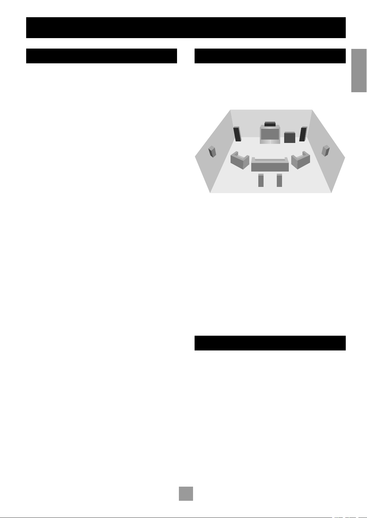
SPEAKER INSTALLATION
The P7 allows connection of up to seven loudspeakers. All speakers,
with the exception of the subwoofer, should be arranged around your
normal viewing/listening position (see diagram). The subwoofer can be
placed almost anywhere and we recommend experimenting with it in
various positions to obtain the best result.
Position your front left and right speakers to achieve a good stereo
image for normal musical reproduction. If they are placed too close
together there will be a lack of spaciousness. Alternatively if they are
placed too far apart the stereo image will appear to have a large hole
in the middle and will be presented in two halves.
The centre speaker allows for a more realistic reproduction of dialogue
and centre sounds as well as wider and better imaging for stereo effects
and background sounds for home cinema use. Do not compromise
on the quality of your centre speaker as it carries all the dialogue for a
home cinema system.
The surround left and right speakers reproduce the ambient sound and
effects present in a multi-channel home cinema system.
The surround back left and surround back right speakers are used to
add extra depth, a more spacious ambience and sound localisation.
A subwoofer will greatly improve the bass performance from your
system. This is useful for reproducing special cinema effects, especially
where a dedicated LFE (Low-Frequency Effects) channel is available, as
with Dolby Digital or DTS Digital Surround encoded discs.
English
CABLES
We recommend the use of high quality screened analogue, digital
and video cables as inferior quality cables will degrade the sound and
picture quality of your system. Only use cables that are designed for
the particular application as other cables will have different impedance
characteristics that will degrade the performance of your system.
Speaker cable length should be minimized and low resistance wire
should be used throughout to ensure efficient power transmission and
avoid audible distortion.
For optimum soundstage imaging, try to keep the right and left speaker
cables the same length. You are also advised to route the signal cables,
speaker cables and mains power cables away from each other to
minimize interference.
Contact your Arcam dealer or installer for details of suitable cables.
5
Page 6
English
7
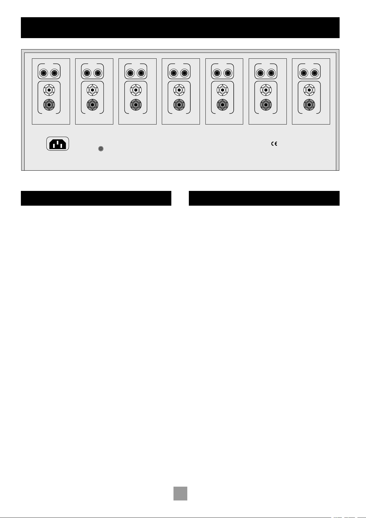
POWER INLET
50 – 60 HZ
~230V
3700 VA MAX
12V TRIGGER
IN
+
–
4-16 OHMS
AUDIO
IN
OUT
+
–
4-16 OHMS
AUDIO
IN
OUT
+
–
4-16 OHMS
AUDIO
IN
OUT
+
–
4-16 OHMS
AUDIO
IN
OUT
+
–
4-16 OHMS
AUDIO
IN
OUT
+
–
4-16 OHMS
AUDIO
IN
OUT
+
–
4-16 OHMS
AUDIO
IN
OUT
7. RS BACK
6. R SURR
5. R FRONT
4. CENTRE
3. L FRONT
2. L SURR
1. LS BACK
Installation
POSITIONING THE UNIT
Place the amplifier on a level, firm surface.
Avoid placing the unit in direct sunlight or near sources of heat
or damp.
Do not place the unit on top of a power amplifier or other
sources of heat.
Ensure adequate ventilation.
The P7 has a variable speed fan for cooling. If the unit is placed
in an enclosed space, such as a bookcase, equipment rack or
cabinet, ensure that there is adequate space and ventilation in
the enclosure for air to flow through the ventilation slots and
cool the amplifier. Inadequate cabinet ventialtion may cause the
P7 to shut down due to thermal overload.
The amplifier is designed to run warm during normal operation.
Ensure that the equipment rack or stand can support the 31kg
weight of the unit.
CONNECTING TO A PRE-AMPLIFIER
ANALOGUE AUDIO INPUTS
It is imperative to connect the pre-amplifier outputs to the module for
that particluar channel, e.g., connect the left surround output to the
module that will be driving the left surround speaker.
All modules are identical. However, we advise you to make connections
corresponding to rear panel labelling, since the amplifier modules are
muted in pairs. Due to the layout of the power supply circuitry in the
P7, you should connect the correct input signal and loudspeaker to
the recommended channel, or the left/right stereo imaging will not be
optimum.
The outputs from the pre-amplifier should be connected to the AUDIO
IN inputs on the P7. Be sure to note which channel from the pre-
amplifier is connected to which power amplifier module, so that the
correct speaker can be connected to that module and the correct
channel identity can be maintained.
If you wish to use four modules to bi-amplify a pair of speakers, or
would like to bi-amplify using another power amp, then you can take
the signal for that channel and feed it on to the additional modules
using the AUDIO OUT phono socket on that module. The signal is then
fed in to the first module, but also fed on to the second module so that
both modules can bi-amplify the loudspeaker.
12V TRIGGER INPUT
If your pre-amp provides a 12V Trigger output, it can be connected to
the 12V TRIGGER IN socket using a 3.5mm jack. This enables the P7 to be
turned on remotely from the pre-amp.
Note that the trigger input is only active when the central power
button on the front panel is depressed.
6
Page 7
Arcam P7 power amplifier
HF
LF
+
+
–
–
+
–
IN OUT
+
–
IN OUT
+
–
IN OUT
+
–
IN OUT
+
–
IN OUT
+
–
IN OUT
+
–
IN OUT
HF
LF
+
+
–
–
HF
LF
+
+
–
–
HF
LF
+
+
–
–
... etc. ...
Right
surround
rear
Right
surround
Right
front Centre
Left
front
Left
surround
Left
surround
rear
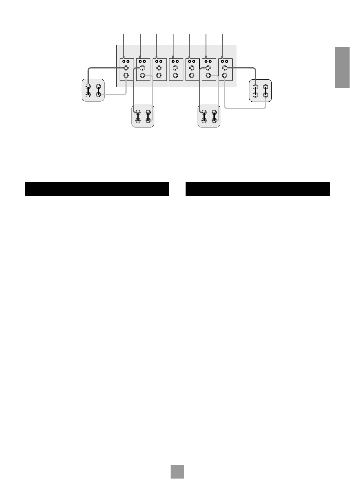
Outputs from multichannel pre-amp (e.g. AV8)
Basic wiring of loudspeakers (three channels omitted for clarity)
English
CONNECTING TO LOUDSPEAKERS
The speakers should be connected to the loudspeaker terminals, as
per the correct input signal. In other words, the Centre channel speaker
should be connected to the module that is being fed the signal for the
Centre channel, and so on, for all the channels.
As with all speaker connections, ensure that polarity is maintained
when connecting the speakers (i.e., red (+) to red; black (–) to black).
To bi-wire or bi-amplify your speakers, refer to the section towards the
end of this handbook where diagrams are provided. If you are unsure as
to how your system should be connected, or need advice on bi-amping,
please consult your Arcam dealer.
CONNECTING TO A POWER SUPPLY
MAINS LEAD
The appliance is normally supplied with a moulded mains plug already
fitted to the lead. If for any reason the plug needs to be removed, it
must be disposed of immediately and securely, as it is a potential shock
hazard when inserted into the mains socket. Should you require a new
mains lead, contact your Arcam dealer.
WRONG PLUG?
Check that the plug supplied with the unit fits your supply and that your
mains supply voltage agrees with the voltage setting (100V, 115V or
230V) indicated on the rear panel of the unit.
If your mains supply voltage or mains plug is different, consult your
Arcam dealer or Arcam Customer Support on +44 (0)1223 203200.
PLUGGING IN
Push the plug (high current IEC line socket) of the power cable supplied
with the unit into the POWER INLET socket in the back of the unit. Make
sure it is pushed in firmly.
The P7 has been designed so that a standard-rating IEC cable (which
has insufficient current rating) cannot be plugged into the P7. Only high
current power cables can be connected.
Put the plug on the other end of the cable into your power supply
socket and switch the socket on.
7
Page 8

English
9
Operating your P7
P7 MULTICHANNEL POWER AMPLIFIER
1 2 3 4 5 6 7
FRONT PANEL LAYOUT
The P7 front panel has a single control: a centrally located power on/off
button.
POWER
Switches the unit on and off. Note that the modules are turned on
individually to stagger the surge created when a powerful amplifier
is switched on (i.e., it provides a ‘soft start’). This reduces the surge
current drawn from the domestic power supply.
STATUS LEDS
A separate LED indicates the status of each of the seven channels of
the P7.
The LEDs cycle through red, orange, then green to indicate the status
from powered-up (initialised), stabilised and active respectively.
All LEDs are off in standby mode.
OPERATING PROCEDURE
Once the relevant connections have been made, the P7 can be
switched on using the central button on the front panel.
SWITCHING ON
It is recommended that you switch on your pre-amp or controller
before powering up the P7 power amp.
Normal powering up is indicated by the following sequence of front
panel LED indicators:
1. On pressing the power switch, all LEDs turn red.
2. After approximately half-a-second, the centre LED turns amber.
3. The LEDs continue turning amber from the centre to the edges
in pairs, with intervals of approximately one second.
4. The centre LED turns green and a relay ‘click’ is heard.
5. The LEDs continue turning green from the centre to the edges
in pairs, along with relay ‘clicks’, with intervals of approximately
one second.
If the LEDs do not follow this sequence when the P7 is powered up,
or behave abnormally at any time during use, then consult the table of
‘Fault status indicators’ on page 11 to discover why the amplifier is in
protection mode.
SWITCHING OFF
To shut down, switch the P7 power amp off first, followed by the preamp or controller.
This eliminates the chance of any ‘thumps’ or power spikes being fed
through to the power amplifier and potentially causing damage to the
system.
NOTE: It is recommended that if the unit is switched off, then it
should not be switched on again for at least 20 seconds from when
it was turned off. This allows the amplifier’s power supply to discharge
fully before it is switched on again.
8
Page 9
Bi-wiring and bi-amping loudspeakers
Arcam P7 power amplifier
HF
LF
+
+
–
–
+
–
IN
OUT
Arcam P7 power amplifier
HF
LF
+
+
–
–
+
–
IN
OUT
+
–
IN
OUT
BEFORE YOU START
WARNING: Do not make any connections to your amplifier while
it is switched on or connected to the mains supply.
Before switching on please check all connections thoroughly, making
sure bare wires or cables are not touching the amplifier in the wrong
places (which could cause short circuits) and you have connected
positive (+) to positive and negative (–) to negative.
Always ensure that the volume control on your amplifier is set to
minimum before starting these procedures.
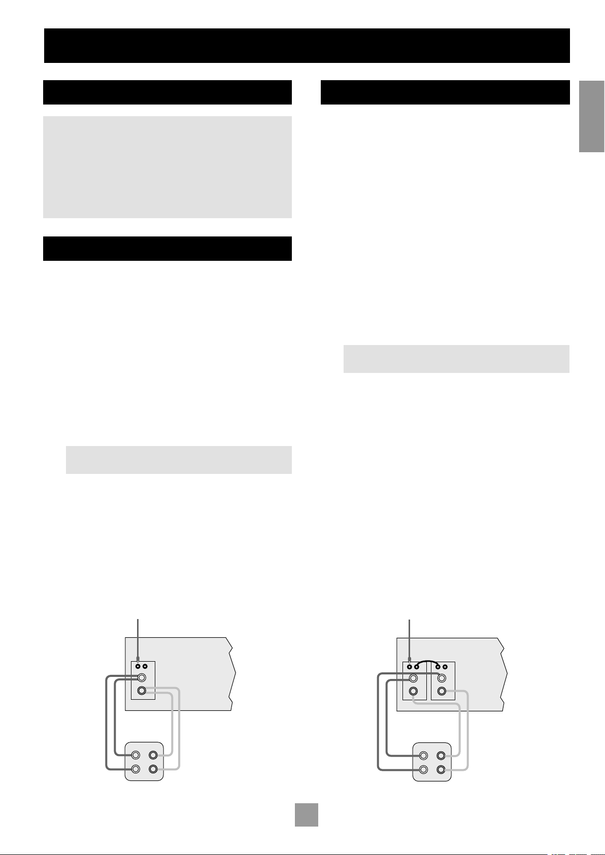
BI-WIRING YOUR LOUDSPEAKERS
Bi-wiring improves the sound of your system because it divides the
high and low frequency signal currents into separate speaker cables.
This avoids signal distortions arising from the high and low frequency
currents interacting with one another within a single cable, as in
conventionally wired systems.
You will need:
Speakers – with four input terminals each: these will be marked HF
(High Frequency + and –) and LF (Low Frequency + and –).
Loudspeaker cables – two pairs of cables per loudspeaker (which
may be joined at the amplifier end if your amplifier has only one pair
of output terminals per channel, as is the case with P7), or a suitably
terminated cable set.
How to bi-wire loudspeakers
1. Remove the terminal links on the rear of your loudspeakers.
NOTE: If you do not remove the shorting links from the
speaker terminals, the speakers will still be single-wired!
2. Connect the cables as shown in the diagram below, ensuring
correct polarity at all times.
BI-AMPING YOUR SYSTEM
The performance of your system can be further enhanced over that
achieved with bi-wiring, by extending the principle one stage further
to include separate amplification for the low and high frequency drive
units in each loudspeaker enclosure.
To bi-amplify your speakers, connect the speaker terminals from one
module to one pair of terminals on the speaker. Connect another
module, or one channel of a separate power amp, to the other pair of
terminals on the speaker, so that two amplifier channels are connected
to that speaker; one for low frequencies and one for high frequencies.
Ensure that in all cases, the positive terminals on the speakers are
connected to the positive (red) terminals on the amplifier, and similarly
for the negative (black) terminals.
NOTE: In order to bi-amplify your speakers, your speakers will need
to be bi-wirable, and have positive and negative terminals for both high
frequency (HF) and low frequency (LF) information. If your speakers are
bi-wirable, ensure that the links between the HF and LF terminals are
removed.
How to set up a bi-amped system
1. Remove the terminal links on the rear of your loudspeakers.
WARNING: This step is essential or damage to your amplifier
may result which is not covered under warranty.
2. Connect the cables as shown in the diagram below, ensuring
correct polarity at all times.
3. Use interconnect cables to connect the OUT socket of the first
channel to the corresponding IN socket of the adjacent channel
of the power amplifier.
English
Bi-wiring using one set of connections on amplifier
Recommended bi-amping configuration
9
Page 10

English
11
Troubleshooting
NO LIGHTS ON THE UNIT
Check that:
the power cord is plugged into the P7 and the mains socket
outlet it is plugged into is switched on.
the plug fuse has not failed, or a circuit-breaker earlier in the
power supply path has not opened.
the power button is pressed in.
RED LED PRESENT
Refer to the ‘Fault Status Indicators’ table if you have an unusual
sequence of LEDs.
NO SOUND IS PRODUCED
Check that:
the correct input has been selected on the pre-amp.
you have assigned the digital input to the correct input source.
the volume is turned up to a reasonable level and ‘MUTE’ is not
displayed on the front panel display on the pre-amp.
your power amplifier(s) are turned on and working correctly.
SOUND IS POOR AND BADLY DISTORTED
Check that:
all cables are making a good connection. If necessary withdraw
the cable from the connector and plug it back in again. (Turn the
power off before doing this.)
you have selected the correct size of speakers to suit your
system in the setup menu of the processor or pre-amp.
HUM ON AN AMPLIFIER OUTPUT
Check that:
all cables are making a good connection. If necessary withdraw
the cable from the connector and plug it back in again. (Turn the
power off before doing this.)
if the hum originates from a ground loop caused by an aerial,
satellite dish or cable supply, you should contact your aerial
contractor.
the signal (interconnect) leads are not wrapped around a mains
lead.
try switching the ground lift on the back panel of the processor
(if available).
THERE IS RADIO/TELEVISION RECEPTION
INTERFERENCE
The P7 has been designed to a very high standards of electromagnetic
compatibility.
Check that:
the aerial/dish cable is routed as far as possible from your P7 and
its cabling.
the cabling used from the aerial/dish is of high quality and
screened.
repositioning the receiving aerial/dish as far as possible from your
P7 and its cabling may bring an improvement.
if the problem persists, contact your aerial contractor.
you are using high quality screened audio cable between your
equipment and that no cables are broken or damaged.
SOUND ONLY COMES FROM SOME OF THE
SPEAKERS
Check that:
all speakers in the system are connected to the P7.
you have configured your pre-amp to include all the speakers in
your system.
you have an appropriate surround sound source selected and
playing through the pre-amp.
for digital sources, check the player is outputting multichannel
data. With some DVD players you are able to select in what
format multi-format encoded discs are outputted, and whether
multichannel data is down mixed to PCM (stereo).
the disc you are playing is a multichannel recording and that the
processor is outputting multichannel audio.
your speaker balance is correct.
all amplifiers are turned on and all channels are working
correctly.
all units are turned on. If the audio is ‘daisy-chained’ from the P7,
make sure that the unit being fed is turned on.
10
Page 11

FAULT STATUS INDICATORS
The LED patterns below indicate the following fault conditions:
LED status Description Amplifier action
All LEDs are green This is the normal operating state of the amplifier. None
During power up all LEDs stay red
for an extended time
During power up or normal
operation, one or more LEDs are
flashing green, with the remaining
LEDs solid red
During power up or normal
operation, one or more LEDs are
flashing green, with the remaining
LEDs NOT solid red
During power up or normal
operation, one or more LEDs are
flashing red, with the remaining
LEDs solid red
During power up or normal
operation, one or more LEDs are
flashing red, with the remaining LEDs
NOT solid red
During power up or normal
operation, one or more LEDs are
flashing amber
During power up or normal
operation, one LED is flashing
amber, with the remaining LEDs
solid red
During power up or normal
operation, all the LEDs are flashing
amber
During normal operation, all the
LEDs are solid red
During power up or normal
operation, one or more LEDs are
flashing amber, with the remaining
LEDs flashing green
During power up or normal
operation, one or more LEDs are
flashing amber, with the remaining
LEDs flashing red
The amplifier is waiting for the DC offset fault lines
to clear. A DC offset fault can occur if an excessive
DC voltage is present at the output of the pre-amp
feeding the P7. Normal operation resumes if the
lines clear in 20 seconds.
The DC fault cannot be cleared. The channels with
the flashing green LEDs represent the amplifier
modules that have a DC offset fault. Alternatlively, a
DC offset fault has reoccurred on the same channel
within 12 seconds of a previous DC offset fault
clearance.
The amplifier is attempting to clear a DC offset fault
on a channel with the flashing green LED.
A short circuit fault cannot be cleared. The flashing
red LEDs represent the amplifier modules with a
short circuit fault. Alternatlively, a short circuit fault
has reoccurred on the same channel within 12
seconds of a previous short circuit fault clearance.
The amplifier is attempting to clear a short circuit
fault on a channel with the flashing red LED.
The amplifier is attempting to clear an over
temperature fault on a channel with the flashing
amber LED.
An over temperature fault has reoccurred on the
same channel within 12 seconds of a previous over
temperature fault clearance.The flashing amber
LEDs represent the amplifier modules with an over
temperature fault.
The amplifier is attempting to clear an over
temperature fault on more than one channel, or the
power transformers have overheated.
An over temperature fault has reoccurred on one
or more channels, or the power transformers have
overheated within 12 seconds of a previous over
temperature fault clearance.
A DC offset fault occurred on one or more
channels while attempting to clear a multiple over
temperature fault.
A short circuit fault occurred on one or more
channels while attempting to clear a multiple over
temperature fault.
To verify excessive DC offset voltage, remove the
interconnect leads (with the P7 switchd off) and turn
on the P7. The fault should have cleared.
The amplifier shuts down. The power switch must be
cycled to reset the amplifier (cycling the trigger does
NOT reset the amplifier).
The amplifer mutes the channel with the fault and its
paired channel. The amplifier stays in this state for up
to two seconds or until the fault clears (whichever is
sooner).
The amplifier shuts down. The power switch must be
cycled to reset the amplifier (cycling the trigger resets
the amplifier).
The amplifer mutes the channel with the fault and its
paired channel. The amplifier stays in this state for up
to half-a-second or until the fault clears (whichever
is sooner).
The amplifer mutes the channel with the fault and its
paired channel and the fan is set to maximum speed.
The amplifier stays in this state until the channel has
cooled.
The amplifier shuts down. The power switch must be
cycled to reset the amplifier (cycling the trigger resets
the amplifier).
The amplifer mutes all channels and the fan is set
to maximum speed. The amplifier stays in this state
until all channels have cooled, or the transformer has
cooled.
The amplifier shuts down. The power switch must be
cycled to reset the amplifier (cycling the trigger resets
the amplifier).
The amplifier shuts down. The power switch must be
cycled to reset the amplifier (cycling the trigger does
NOT reset the amplifier).
The amplifier shuts down. The power switch must be
cycled to reset the amplifier (cycling the trigger resets
the amplifier).
English
11
Page 12

English
13
Technical specications
All measurements are with 230V/50Hz mains power
Continuous output power
All channels driven, 20Hz—20kHz, 8Ω 150W per channel; 1.05kW total
All channels driven, 20Hz—20kHz, 4Ω 230W per channel; 1.62kW total
One or two channels driven at 1kHz, 8Ω 160W per channel
One or two channels driven at 1kHz, 4Ω 250W per channel
One or two channels driven at 1kHz, 3.2Ω 300W per channel
Peak output current capability
±25A per channel
Total harmonic distortion
At any level up to rated power, into 4 or 8Ω <0.05% (20Hz—20kHz); typically <0.005% at 1kHz
Frequency response
±0.2dB (20Hz—20kHz)
–1dB at 1Hz and 100kHz
Residual hum and noise
Ref. full power –122dB, 20Hz–20kHz, unweighted
Voltage gain
x 28.3 (1V input gives 100W/8Ω output)
Input impedance
22kΩ in parallel with 470pF
Output impedance
50mΩ at 20Hz, 1kHz
120mΩ at 20kHz
Power requirements
100, 115V or 230VAC, 50/60Hz, 3kW maximum via heavy duty IEC mains inlet
A soft-start system eliminates large inrush currents at switch on
Physical
Dimensions: W430 x D450 x H180 mm
Weight: 31kg (68 lb) nett; 35kg (77 lb) packed
E&OE
CONTINUAL IMPROVEMENT POLICY
Arcam has a policy of continual improvement for its products. This
means that designs and specifications are subject to change without
notice.
NOTE: All specification values are typical unless otherwise stated.
RADIO INTERFERENCE
The P7 is an audio device which has been designed to very high
standards of electromagnetic compatibility.
The unit can radiate RF (radio frequency) energy. In some cases this
can cause interference with FM and AM radio reception. If this is the
case, keep the P7 and its connecting cables as far from the tuner and its
aerials as possible. Connecting the P7 and the tuner to different mains
sockets can also help to reduce interference.
EC COUNTRIES – These products have been designed to comply with
directive 89/336/EEC.
USA – These products comply with FCC requirements.
12
Page 13

Guarantee
WORLDWIDE GUARANTEE
This entitles you to have the unit repaired free of charge, during the
first two years after purchase, at any authorised Arcam distributor
provided that it was originally purchased from an authorised Arcam
dealer or distributor. The manufacturer can take no responsibility for
defects arising from accident, misuse, abuse, wear and tear, neglect or
through unauthorised adjustment and/or repair, neither can they accept
responsibility for damage or loss occurring during transit to or from the
person claiming under the guarantee.
THE WARRANTY COVERS:
Parts and labour costs for two years from the purchase date. After two
years you must pay for both parts and labour costs. The warranty does
not cover transportation costs at any time.
CLAIMS UNDER GUARANTEE
This equipment should be packed in the original packing and returned
to the dealer from whom it was purchased, or failing this, directly to the
Arcam distributor in the country of residence. It should be sent carriage
prepaid by a reputable carrier – NOT by post. No responsibility can
be accepted for the unit whilst in transit to the dealer or distributor
and customers are therefore advised to insure the unit against loss or
damage whilst in transit.
For further details contact Arcam at:
Arcam Customer Support Department,
Pembroke Avenue, Waterbeach, CAMBRIDGE, CB5 9QR England
Telephone: +44 (0)1223 203200
Fax: +44 (0)1223 863384
Email: support@arcam.co.uk
PROBLEMS?
Always contact your dealer in the first instance.
If your dealer is unable to answer any query regarding this or any
other Arcam product please contact Arcam Customer Support on
+44 (0) 1223 203200 or write to us at the above address and we will
do our best to help you.
ON LINE REGISTRATION
You can register your Arcam product on line at:
www.arcam.co.uk
English
13
Page 14

Français15Français
14
Page 15

Utilisation de ce manuel
Ce manuel a été conçu pour vous donner toutes les informations
nécessaires pour installer, connecter, mettre en place et utiliser
l’amplificateur de puissance multicanaux Arcam FMJ P7.
Il se peut que le P7 ait été installé et mis en place dans le cadre de
votre installation Hi-Fi ou home cinéma par un revendeur Arcam agréé.
Dans ce cas, vous pouvez souhaiter passer les sections de ce manuel
qui traitent de l’installation et de la mise en place de l’unité. Utilisez le
Sommaire pour vous guider vers les sections qui vous intéressent.
SÉCURITÉ
Les consignes de sécurité sont énoncées sur la page suivante de ce
manuel.
Il s’agit dans de nombreux cas de précautions logiques mais, pour votre
propre sécurité et pour être sûr de ne pas endommager l’unité, nous
vous recommandons fortement de les lire. Cet appareil est un produit
de classe 1 qui requiert une connexion à la terre.
TABLE DES MATIÈRES
Utilisation de ce manuel............................................................. 15
Consignes de sécurité ................................................................16
Conseils de sécurité importants................................................. 16
Conformité aux normes de sécurité........................................16
Préparation du P7........................................................................ 17
Introduction............................................................................................ 17
Installation des haut-parleurs........................................................17
Câbles......................................................................................................... 17
Installation .....................................................................................18
Positionnement de l’appareil......................................................... 18
Raccordement à un préamplicateur....................................... 18
Raccordement aux haut-parleurs...............................................19
Branchement à une source d’alimentation ........................... 19
Fonctionnement de votre P7....................................................20
Schéma du panneau avant..............................................................20
Procédure de fonctionnement.....................................................20
Avent de commencer....................................................................... 21
Bi-câblage de vos haut-parleurs .................................................. 21
Bi-câblage et bi-amplication des haut-parleurs................... 21
Bi-amplication de votre système.............................................. 21
Dépannage..................................................................................... 22
Indicateurs d’état d’erreur ..............................................................23
Spécications techniques ...........................................................24
Garantie......................................................................................... 25
Inscription en ligne.............................................................................. 25
15
Page 16

Français
17
Consignes de sécurité
RISQUE DE CHOC ELECTRIQUE
NE PAS OUVRIR
ATTENTION
CAUTION
RISK OF ELECTRIC
SHOCK DO NOT OPEN
ATTENTION : Pour éviter tout risque de choc électrique, ne pas
enlever le couvercle (ou le panneau arrière). Aucune intervention n’est
possible pour l’utilisateur. Pour le service, voir un personnel qualifié.
AVERTISSEMENT : Pour éviter tout risque d’incendie ou de choc
électrique, ne pas exposer l’appareil à la pluie ou à l’humidité.
Le symbole d’un éclair dans un triangle a pour objet d’avertir l’utilisateur
de la présence à l’intérieur du boîtier de l’appareil de “tension électrique
dangereuse” non-isolée et de force suffisante à constituer un risque de
choc électrique.
Le point d’exclamation dans un triangle a pour objet d’avertir l’utilisateur
de la présence de renseignements importants concernant l’utilisation et
la maintenance (le service après vente) dans la documentation fournie
avec le produit.
ATTENTION : Au Canada et aux États-Unis, pour éviter tout risque de
choc électrique, alignez la lame large de la fiche secteur avec la fente
large de la prise murale, puis enfoncez la fiche complètement.
CONSEILS DE SÉCURITÉ IMPORTANTS
Cet appareil a été conçu et fabriqué conformément aux normes de
qualité et de sécurité les plus strictes. Vous devez cependant observer
les précautions suivantes lors de son installation et de son utilisation.
1. Avertissements et consignes
Il est conseillé de lire les consignes de sécurité et d’utilisation avant de
mettre cet appareil en marche. Conservez ce manuel pour pouvoir vous
y référer par la suite et respectez scrupuleusement les avertissements
figurant dans ce manuel ou sur l’appareil lui-même.
2. Eau et humidité
L’installation d’un appareil électrique à proximité d’une source d’eau
présente de sérieux risques. Il ne faut pas utiliser l’appareil à proximité
d’un point d’eau : près d’une baignoire, d’un lavabo, d’un évier, dans une
cave humide ou à côté d’une piscine, etc.
3. Chute d’objets ou infiltration de liquides
Veillez à ne pas laisser tomber d’objets ni faire couler de liquides à
travers l’une des ouvertures du boîtier. Ne posez pas d’objet contenant
du liquide sur l’appareil.
4. Ventilation
Évitez de placer l’appareil sur un lit, un canapé, un tapis ou une surface
similaire instable, ou dans une bibliothèque ou un meuble fermé, ce qui
risquerait d’empêcher une ventilation correcte. Pour permettre une
ventilation appropriée, il est conseillé de prévoir au minimum un espace
de 5 cm de chaque côté et au-dessus de l’appareil.
5. Exposition à la chaleur
Ne placez pas l’appareil près d’une flamme nue ou d’un dispositif
produisant de la chaleur, tel un radiateur, un poêle ou autre appareil (y
compris les amplificateurs).
6. Conditions climatiques
L’appareil est conçu pour fonctionner dans des climats modérés.
7. Étagères et supports
Utilisez uniquement des étagères ou des supports pour appareils
audio. Si l’appareil est posé sur un support mobile, déplacez celui-ci
avec précaution, pour éviter tout risque de chute.
8. Nettoyage
Débranchez l’appareil du secteur avant de le nettoyer.
Pour le nettoyage, utilisez un chiffon doux, humide et non pelucheux.
N’utilisez pas de diluant pour peinture ou de solvant chimique.
L’emploi d’aérosols ou de produits de nettoyage pour meubles est
déconseillé, car le passage d’un chiffon humide risquerait de laisser des
marques blanches indélébiles.
9. Alimentation secteur
Branchez l’appareil uniquement sur une alimentation secteur du type
mentionné dans le manuel d’utilisation ou indiqué sur l’appareil luimême.
10. Protection des cordons secteur
Veillez à ce que les cordons secteur ne se trouvent pas dans un lieu de
passage ou pincés par un objet quelconque. Prêtez particulièrement
attention aux cordons et fiches secteur à leurs points de sortie de
l’appareil.
11. Mise à la terre
Assurez-vous que l’appareil est correctement mis à la terre.
12. Câbles haute tension
Évitez de monter une antenne extérieure à proximité de câbles haute
tension.
13. Périodes de non-utilisation
Si l’appareil possède une fonction de mise en veille, un courant faible
continuera de circuler lorsqu’il est réglé sur ce mode. Débranchez
le cordon secteur de la prise murale si l’appareil doit rester inutilisé
pendant une période prolongée.
14. Odeur suspecte
Arrêtez et débranchez immédiatement l’appareil en cas de fumée ou
d’odeur anormale. Contactez immédiatement votre revendeur.
15. Service
Ne tentez pas d’effectuer d’autres opérations que celles mentionnées
dans ce manuel. Toute autre intervention doit être effectuée par un
personnel qualifié.
16. Entretien par un personnel qualifié
L’appareil doit être entretenu par du personnel qualifié lorsque :
A. la fiche ou le cordon secteur a été endommagé,
B. des objets sont tombés ou du liquide a coulé dans l’appareil,
C. l’appareil a été exposé à la pluie,
D. l’appareil ne semble pas fonctionner normalement ou présente
des altérations dans son fonctionnement,
E. l’appareil est tombé ou le boîtier a été endommagé.
17. Transport de l’unité
Cet amplificateur pèse 31 kg, il faut donc faire extrêmement attention
lorsque vous soulevez ou déplacez l’unité. Nous conseillons de porter
l’unité à deux personnes.
CONFORMITÉ AUX NORMES DE SÉCURITÉ
Cet appareil est conçu pour répondre à la norme internationale de
sécurité électrique IEC 60065.
16
Page 17

Préparation du P7
Surround arrière
gauche
Surround arrière
droite
CentreAvant
gauche
Avant
droite
Caisson de grave
Surround
gauche
Surround
droite
INTRODUCTION
L’Amplificateur de puissance multicanaux P7 est construit selon les
normes habituelles élevées de qualité et de fabrication d’Arcam. Il
s’agit d’un amplificateur de puissance multicanaux hautes performances,
offrant 150 W par canal. Il est évidemment bien adapté à l’amplification
multicanaux pour le home cinéma et assure également des
performances stéréo d’une qualité exceptionnelle avec des sources à
deux canaux. Le P7 est le complément idéal du Préampli processeur
FMJ AV8.
Chaque module d’amplificateur de puissance est identique et isolé
électriquement des autres modules par des circuits opto-isolés qui
assurent que chaque module amplificateur dispose de sa propre
alimentation isolée. Cela permet à l’amplificateur d’assurer une
excellente séparation des canaux et une très faible distorsion.
Le P7 dispose également de prises entrée et sortie phono pour que
le signal soit transmis à chaque canal, afin d’assurer la transmission du
signal à des amplificateurs d’alimentation supplémentaires pour des
haut-parleurs situés dans d’autres pièces ou pour bi-amplifier l’un des
haut-parleurs. Si le P7 est utilisé dans le cadre d’un système sonore
surround à cinq canaux, les deux modules de rechange (« L surround
rear » (surround arrière gauche) et « R surround rear » (surround
arrière droit)) peuvent être utilisés conjointement avec les modules
principaux (« L front » (avant droit) et « R front » (avant gauche))
pour bi-amplifier les haut-parleurs gauche et droit avant souhaités.
Le P7 peut facilement être utilisé avec divers types de haut-parleurs, y
compris les haut-parleurs certifiés THX. Le fait d’avoir la certification
THX signifie que le P7 a obtenu la spécification rigoureuse THX Ultra2,
ce qui lui permet de reproduire des signaux THX Surround EX à partir
de bandes sons Dolby Digital et DTS, lorsque le signal est émis à partir
d’un processeur de type THX Surround EX, tel que le Arcam AV8.
L’installation personnalisée du P7 vers une salle d’écoute est un
processus important qui requiert beaucoup d’attention à chaque étape.
C’est la raison pour laquelle les informations d’installation sont très
complètes et doivent être suivies à la lettre. Ce manuel a été écrit en
partant du principe que l’installateur est habitué à installer des systèmes
audio/vidéo.
INSTALLATION DES HAUT-PARLEURS
Le P7 peut être raccordé à un maximum de 7 haut-parleurs. Tous les hautparleurs, à l’exception du caisson de grave, devraient être organisés autour
de votre position de visualisation/d’écoute (voir le schéma). Le caisson
de grave peut être placé à peu près partout et nous recommandons
d’essayer diverses positions pour obtenir le meilleur résultat.
Français
Placez les haut-parleurs avant gauche et droit de façon à obtenir
une bonne image stéréo pour les reproductions musicales normales.
S’ils sont placés trop près l’un de l’autre, l’image stéréo sera trop
étriquée. Par ailleurs, s’ils sont placés trop loin l’un de l’autre, vous aurez
l’impression que l’image stéréo a un trou important au milieu et qu’elle
sera présentée en deux moitiés.
Le haut-parleur central permet une reproduction plus réalistedes
dialogues et des sons centraux et permet également d’obtenir une
image sonore plus large et plus nette pour les effets stéréo et les fonds
sonores utilisés pour le home cinéma. Soyez exigent sur la qualité de
votre haut-parleur central car c’est lui qui reproduit l’ensemble des
dialogues dans un système de home cinéma.
Les haut-parleurs surround gauche et droit reproduisent les sons et
effets d’ambiance présents dans un système home cinéma multicanaux.
Les haut-parleurs surround arrière gauche et surround arrière droit
sont utilisés pour ajouter de la profondeur, une ambiance plus spacieuse
et la localisation des sons.
Un caisson de grave augmentera grandement les performances des
graves de votre système. Cela s’avère utile pour reproduire les effets
spéciaux cinématographiques, en particulier si vous disposez d’un canal
dédié aux LFE (Low-Frequency Effects), par exemple avec des disques
codés Dolby Digital ou DTS Digital Surround.
CÂBLES
Nous vous recommandons d’utiliser des câbles analogiques isolés,
numériques et vidéo de haute qualité car des câbles de qualité
inférieure vont dégrader la qualité sonore et visuelle de votre système.
N’utilisez que des câbles conçus pour cette application particulière car
les autres câbles auront des caractéristiques d’impédance différentes qui
dégraderont les performances de votre système. Il convient de réduire
le plus possible la longueur des câbles des haut-parleurs et d’utiliser
des fils à faible niveau de résistance pour l’ensemble du système afin
d’assurer une transmission efficace et d’éviter des distorsions audibles.
Pour une représentation optimale de l’espace sonore, essayez de
maintenir une longueur identique pour les câbles des haut-parleurs
droit et gauche. Il vous est également conseillé d’acheminer les câbles
de signaux, les câbles des haut-parleurs et les câbles d’alimentation
principale écartés les uns des autres afin de réduire les interférences.
Contactez votre revendeur Arcam ou votre installateur pour plus de
détails sur les câbles adaptés.
17
Page 18

Français
19
POWER INLET
50 – 60 HZ
~230V
3700 VA MAX
12V TRIGGER
IN
+
–
4-16 OHMS
AUDIO
IN
OUT
+
–
4-16 OHMS
AUDIO
IN
OUT
+
–
4-16 OHMS
AUDIO
IN
OUT
+
–
4-16 OHMS
AUDIO
IN
OUT
+
–
4-16 OHMS
AUDIO
IN
OUT
+
–
4-16 OHMS
AUDIO
IN
OUT
+
–
4-16 OHMS
AUDIO
IN
OUT
7. RS BACK
6. R SURR
5. R FRONT
4. CENTRE
3. L FRONT
2. L SURR
1. LS BACK
Installation
POSITIONNEMENT DE L’APPAREIL
Placer l’amplificateur sur une surface plane et ferme.
Eviter de placer l’appareil à la lumière directe du soleil ou près de
sources de chaleur ou d’humidité.
Ne pas placer l’appareil au-dessus d’un amplificateur de puissance
ou de toute autre source de chaleur.
Assurer une ventilation adéquate.
Le P7 dispose d’un ventilateur à vitesse variable pour assurer
le refroidissement. Si l’appareil est placé dans un espace clos,
par exemple, une bibliothèque, une étagère prévue pour
l’équipement ou une armoire, assurez-vous qu’il y a suffisamment
d’espace et de ventilation pour que l’air circule par les fentes de
ventilation et refroidisse l’amplificateur. Une ventilation inadaptée
peut provoquer l’arrêt du P7 en raison d’une surchauffe.
L’amplificateur est conçu pour être tiède au toucher pendant le
fonctionnement normal.
Vérifier que l’étagère ou le support sur lequel est posé l’appareil
peut supporter son poids de 31kg.
RACCORDEMENT À UN PRÉAMPLIFICATEUR
ENTRÉES AUDIO ANALOGIQUES
Les sorties du préamplificateur doivent impérativement être connectées
au module pour ce canal particulier, par exemple, connectez la sortie
surround gauche au module qui alimente le haut-parleur surround
gauche.
Tous les modules sont identiques. Toutefois, nous vous conseillons de
réaliser les branchements correspondant aux étiquettes du panneau
arrière car les modules de l’amplificateur sont mis en sourdine par
paires. En raison du schéma du circuit d’alimentation du P7, vous
devriez raccorder correctement le signal d’entrée et le haut-parleur
au canal recommandé ou l’image stéréo gauche/droite ne sera pas
optimale.
Les sorties du préamplificateur doivent être raccordées aux entrées
AUDIO IN du P7. Notez quel canal du préamplificateur est raccordé
à quel module de l’amplificateur de puissance, de façon à pouvoir
connecter le haut-parleur correct à ce module et à maintenir l’identité
du canal correct.
Si vous souhaitez utiliser quatre modules pour biamplifier une paire
de haut-parleurs, ou si vous voulez bi-amplifier à l’aide d’un autre
amplificateur de puissance, vous devez prendre le signal pour ce canal
et le diriger vers les modules supplémentaires à l’aide de la prise phono
AUDIO OUT sur ce module. Le signal est ensuite transmis au premier
module, mais également au second module de façon à ce que les deux
modules puissent bi-amplifier le haut-parleur.
ENTRÉE TRIGGER INPUT 12V
18
Si votre préampli fournit une sortie Trigger output 12V, il peut être
raccordé à la prise 12V TRIGGER IN à l’aide d’une prise jack 3,5mm. Cela
permet d’activer le P7 à distance du préampli.
Notez que l’entrée TRIGGER INPUT n’est active que lorsque le bouton
d’alimentation central sur le panneau frontal est enfoncé.
Page 19

HF
LF
+
+
–
–
+
–
IN OUT
+
–
IN OUT
+
–
IN OUT
+
–
IN OUT
+
–
IN OUT
+
–
IN OUT
+
–
IN OUT
HF
LF
+
+
–
–
HF
LF
+
+
–
–
HF
LF
+
+
–
–
Sorties du préamplificateur (par exemple, AV8)
Surround
arrière
gauche
Surround
arrière
droite Centre
Avant
gauche
Avant
droite
Surround
gauche
Surround
droite
Amplicateur de Puissance Multicanaux P7
Câblage de base des haut-parleurs (trois canaux omis pour des raisons de clarté)
Français
RACCORDEMENT AUX HAUT-PARLEURS
Les haut-parleurs doivent être connectés aux bornes de haut-parleurs,
en fonction du signal d’entrée correct. En d’autres termes, le hautparleur du canal Central doit être connecté au module qui fournit le
signal du canal Central et ainsi de suite, pour tous les canaux.
Comme pour tous les branchements de haut-parleurs, vérifiez que la
polarité est respectée lors du raccordements des haut-parleurs (c’està-dire rouge (+) avec rouge ; noir (–) avec noir).
Pour bi-câbler ou bi-amplifier vos haut-parleurs, reportez-vous à la
section vers la fin de ce manuel contenant les schémas. Si vous n’êtes
pas sûr de la façon dont il convient de connecter votre système, ou
si vous avez besoin de conseil à propos de la biamplification, veuillez
consulter votre revendeur Arcam.
BRANCHEMENT À UNE SOURCE D’ALIMENTATION
CORDON D’ALIMENTATION
Normalement, l’appareil est fourni avec une prise de cordon
d’alimentation moulée déjà ajustée sur le cordon. Si, pour quelque
raison que ce soit, la prise doit être retirée, il convient de la jeter
immédiatement et de façon sécurisée, car elle risque de provoquer
un choc électrique. Si vous avez besoin d’un nouveau cordon
d’alimentation, adressez-vous à votre revendeur Arcam.
MAUVAISE PRISE ?
Vérifiez que la prise fournie avec l’appareil s’adapte à votre alimentation
et que la tension d’alimentation correspond au réglage de tension
(100V, 115V ou 230V) indiqué sur le panneau arrière de l’appareil.
Si la tension d’alimentation ou la prise principale est différente,
consultez votre revendeur Arcam ou le support technique d’Arcam au
+44 (0)1223 203200.
RACCORDEMENT AU RÉSEAU
Introduisez la prise (prise de ligne IEC fort courant) du câble
d’alimentation fournie avec l’appareil dans la prise POWER INLET à
l’arrière de l’appareil. Assurez-vous qu’elle est bien enfoncée.
Le P7 a été conçu de façon à ce qu’il soit impossible d’y brancher un
câble IEC de courant nominal standard (dont le courant nominal est
insuffisant). Seuls les câbles d’alimentation en courant haute tension
peuvent être raccordés.
Placer la prise sur l’autre extrémité du câble dans la prise d’alimentation
et mettre la prise sous tension.
19
Page 20

Français
21
Fonctionnement de votre P7
P7 MULTICHANNEL POWER AMPLIFIER
1 2 3 4 5 6 7
SCHÉMA DU PANNEAU AVANT
Le panneau avant du P7 présente une commande unique : un bouton
on/off d’alimentation situé au centre.
ALIMENTATION
Met l’appareil sous tension et hors tension. Notez que les modules sont
tournés individuellement afin d’échelonner la surtension créée lors de
la mise sous tension d’un amplificateur puissant (en d’autres termes,
cela permet d’assurer un « départ en douceur »). Cela permet de
réduire les surcharges de tension de l’alimentation domestique.
LED D’ÉTAT
Une LED distincte indique l’état de chacun des sept canaux du P7.
Le cycle des LED, de rouge à orange puis vert, indique respectivement
la mise sous tension (initialisé), la stabilisation et l’activation.Toutes les
LED sont hors tension (off) en mode veille.
PROCÉDURE DE FONCTIONNEMENT
Une fois que les branchements nécessaires ont été effectués, le P7 peut
être mis sous tension à l’aide du bouton central situé sur le panneau
avant.
3. Les LED deviennent orange par paires les unes après les autres
en partant du centre vers les bords, à un intervalle d’environ une
seconde.
4. La LED centrale devient verte et le « clic » du relais se fait
entendre.
5. Les LED deviennent verte par paires les unes après les autres en
partant du centre vers les bords et des « clics » de relais se font
entendre à des intervalles d’environ une seconde.
Si les LED ne suivent pas cette séquence lorsque le P7 est mis sous
tension, ou si elles se comportent de façon anormale à tout moment
pendant l’utilisation, consultez le tableau des « Indicateurs d’état
d’erreur » à la page 23 pour savoir pourquoi l’amplificateur est en
mode protection.
MISE HORS TENSION
Pour éteindre le système, commencez par mettre l’amplificateur de
puissance P7 hors tension, suivi du préampli ou du contrôleur.
Cela élimine tout « bruit sourd » outoute transmission de
crêtes d’alimentation à l’amplificateur de puissance qui risquerait
d’endommager le système.
REMARQUE : si l’appareil est mis hors tension, il est recommandé
d’attendre au moins 20 secondes avant de le remettre sous tension.
Cela permet de décharger l’alimentation de l’amplificateur avant de le
remettre sous tension.
MISE SOUS TENSION
Il est recommandé de mettre sous tension votre préampli ou votre
contrôleur avant de mettre sous tension l’amplificateur de puissance
P7.
La mise sous tension normale est indiquée par la séquence suivante au
niveau des indicateurs LED du panneau avant :
1. Lorsque vous appuyez sur le bouton d’alimentation, toutes les
LED deviennent rouges.
2. Après environ une demi seconde, la LED centrale devient
orange.
20
Page 21

Bi-câblage et bi-amplication des haut-parleurs
Amplicateur de Puissance
Multicanaux P7
HF
LF
+
+
–
–
+
–
IN
OUT
HF
LF
+
+
–
–
+
–
IN
OUT
+
–
IN
OUT
Amplicateur de Puissance
Multicanaux P7
AVENT DE COMMENCER
AVERTISSEMENT : ne pas effectuer de branchement si votre
amplificateur est sous tension ou connecté à l’alimentation principale.
Avant de mettre l’appareil sous tension, vérifiez bien tous les
branchements et assurez-vous qu’aucun fil ou câble nu ne touche
l’amplificateur au mauvais endroit (ce qui pourrait provoquer un
court circuit). Contrôlez également que vous avez connecté la borne
positive (+) au plus et la borne négative (–) au moins.
Vérifiez toujours que le volume sur votre amplificateur est réglé au
minimum avant de commencer ces procédures.
BI-CÂBLAGE DE VOS HAUT-PARLEURS
Le bi-câblage améliore la qualité du son de votre système car il divise
les courant des signaux haute fréquence et basse fréquence vers des
câbles de haut-parleurs distincts. Cela évite les distorsions de signaux
découlant de l’interaction des courants haute fréquence et basse
fréquence entre eux dans un câble unique, comme cela a lieu dans les
systèmes câblés de façon traditionnelle.
Vous avez besoin de :
Haut-parleurs – avec quatre bornes d’entrée chacun : ils porteront
la marque HF (Haute Fréquence + et –) et LF (Basse fréquence [Low
Frequency] + et –).
Câbles de haut-parleurs – deux paires de câbles par haut-parleur
(pouvant être joints à l’extrémité de l’amplificateur si celui-ci n’a qu’une
seule paire de bornes de sortie par canal, comme c’est le cas avec le
P7). Alternativement, utilisez un jeu de câble au bout adapté.
Procédure pour bi-câbler les haut-parleurs
1. Retirez les liaisons aux bornes à l’arrière de vos haut-parleurs.
REMARQUE : si vous n’enlevez pas les contacts de court-
circuit des bornes des haut-parleurs, ceux-ci seront monocâblés !
2. Connectez les câbles comme indiqué dans le schéma ci-dessous,
en vous assurant à tout moment que la polarité est correcte.
BI-AMPLIFICATION DE VOTRE SYSTÈME
Les performances de votre système peuvent être encore améliorées
par rapport au niveau obtenu grâce au bi-câblage. Pour cela, il faut
développer davantage le principe pour inclure l’amplification distincte
des lecteurs haute fréquence et basse fréquence dans chaque
enceinte.
Pour bi-amplifier vos haut-parleurs, connectez les bornes de hautparleurs d’un module à une paire de bornes sur le haut-parleur.
Connectez un autre module, ou un canal d’un amplificateur de
puissance distinct à l’autre paire de bornes sur le haut-parleur, de
sorte que les deux canaux de l’amplificateur soient connectés à ce
haut-parleur ; un pour les basses fréquences et l’autre pour les hautes
fréquences.
Assurez-vous que dans tous les cas, les bornes positives sur les
haut-parleurs sont connectées aux bornes positives (rouge) sur
l’amplificateur et de même pour les bornes négatives (noires).
REMARQUE : afin de bi-amplifier vos haut-parleurs, ceux-ci doivent
pouvoir être bi-câblés et être équipés de bornes positives et négatives
pour les informations haute fréquence (HF) et basse fréquence (LF). Si
vos haut-parleurs peuvent être bi-câblés, vérifiez que les liaisons entre
les bornes HF et LF ont été retirées.
Comment mettre en place un système bi-amplifié :
1. Retirer les liaisons des bornes à l’arrière de vos haut-parleurs.
AVERTISSEMENT : cette étape est essentielle car votre
amplificateur pourrait sans cela subir des dommages non
couverts par la garantie.
2. Connectez les câbles comme indiqué dans le diagramme cidessous, en vous assurant à tout moment que la polarité est
correcte.
3. Utilisez des câbles d’interconnexion pour connecter la prise OUT
du premier canal à la prise IN correspondante du canal adjacent
de l’amplificateur de puissance.
Français
Bi-câblage à l’aide d’un jeu de connexions sur l’amplificateur
Configuration de bi-amplification recommandée
21
Page 22

Français
23
Dépannage
AUCUNE LUMIÈRE SUR L’APPAREIL
Vérifiez que :
le cordon d’alimentation est raccordé au P7 et à la prise
d’alimentation principale (secteur). Si la prise de courant est
équipée d’un interrupteur, vérifiez que celui-ci est bien mis en
circuit (on).
le fusible de la prise n’a pas sauté, ou qu’un disjoncteur ne s’est
pas déclenché en amont du circuit d’alimentation.
le bouton d’alimentation est enfoncé.
LED ROUGE ALLUMÉE
Reportez-vous au tableau des « Indicateurs d’état d’erreur » si vous
constatez une séquence inhabituelle des LED.
AUCUN SON N’EST PRODUIT
Vérifiez que :
l’entrée qui a été sélectionnée sur le préampli est correcte.
vous avez affecté l’entrée numérique à la source d’entrée
correcte.
le volume est à un niveau raisonnable et que « MUTE » ne
s’affiche pas sur l’écran du panneau avant du préampli.
votre/vos amplificateur(s) de puissance sont sous tension et
fonctionnent correctement.
LE SON EST DE MAUVAISE QUALITÉ ET
DÉFORMÉ
Vérifiez que :
tous les câbles sont bien branchés. Si nécessaire, retirez le
câble du connecteur et rebranchez-le. (Eteignez l’appareil avant
d’effectuer cette opération.)
vous avez sélectionné la bonne taille de haut-parleurs pour
votre système dans le menu d’installation du processeur ou du
préampli.
SOUFFLE SUR UNE SORTIE D’AMPLIFICATEUR
Vérifiez que :
tous les câbles sont bien branchés. Si nécessaire, retirez le
câble du connecteur et rebranchez-le. (Eteignez l’appareil avant
d’effectuer cette opération.)
si le souffle provient d’une boucle de terre due à une antenne,
une parabole ou une liaison par câble, veuillez contacter le
vendeur de l’antenne.
les fils du signal (interconnexion) ne sont pas enroulés autour
d’un câble d’alimentation principale.
essayez de basculer le commutateur d’annulation de la mise
à la terre (ground lift) situé à l’arrière du processeur (le cas
échéant).
IL Y A DES INTERFÉRENCES DE RÉCEPTION
RADIO/TÉLÉVISION
Le P7 a été conçu pour fonctionner selon des normes très strictes de
compatibilité électromagnétique.
Vérifiez que :
le câble d’antenne/de parabole passe aussi loin que possible du
P7 et de son câblage.
le câblage utilisé pour l’antenne/la parabole est isolé et de haute
qualité.
repositionner l’antenne/la parabole de réception aussi loin
que possible du P7 et de son câblage peut apporter une
amélioration.
vous utilisez un câble audio isolé de haute qualité entre les
différentes composantes de votre équipement et aucun câble
n’est cassé ou endommagé.
Si le problème persiste, contactez le vendeur de l’antenne.
LE SON NE PROVIENT QUE DE CERTAINS HAUTPARLEURS
Vérifiez que :
tous les haut-parleurs du système sont connectés au P7.
vous avez configuré votre préampli de sorte à inclure tous les
haut-parleurs de votre système.
la source sonore surround sélectionnée est adéquate et passe
par le préampli.
pour les sources numériques, vérifiez que le lecteur émet des
données multicanaux. Avec certains lecteurs de DVD, vous
pouvez sélectionner le format de lecture des disques codés en
multi-format et vous pouvez choisir que les données multicanaux
soient ou non mixées par PCM (stéréo).
le disque lu est un enregistrement multicanaux et le processeur
traite des données audio multicanaux.
la balance de votre haut-parleur est correcte.
tous les amplificateurs sont sous tension et tous les canaux
fonctionnent correctement.
tous les appareils sont sous tension. Si les données audio sont
« en cascade » à partir du P7, assurez-vous que l’appareil
auxquelles elles sont transmises est sous tension.
22
Page 23

INDICATEURS D’ÉTAT D’ERREUR
Les schémas de LED ci-dessous indiquent les conditions d’erreur suivantes :
Etat de la LED Description Action de l’amplificateur
Toutes les LED sont vertes. Cela correspond à l’état de fonctionnement normal
Lors de la mise sous tension, toutes
les LED restent rouges pendant une
période prolongée.
Pendant la mise sous tension ou
en fonctionnement normal, une
ou plusieurs LED de couleur verte
clignote(nt), les autres LED étant
rouges fixes.
Pendant la mise sous tension ou
en fonctionnement normal, une
ou plusieurs LED de couleur
verte clignote(nt), les autres LED
N’ETANT PAS rouges fixes.
Pendant la mise sous tension ou en
fonctionnement normal, une LED de
couleur rouge clignote, les autres
LED étant rouges fixes.
Pendant la mise sous tension ou en
fonctionnement normal, une LED
de couleur rouge (ou plusieurs)
clignote(nt), les autres LED
N’ETANT PAS rouges fixes.
Pendant la mise sous tension ou
en fonctionnement normal, une ou
plusieurs LED oranges clignote(nt).
Pendant la mise sous tension ou en
fonctionnement normal, une LED
orange clignote, les autres LED étant
rouges fixes.
Pendant la mise sous tension ou en
fonctionnement normal, toutes les
LED clignote(nt) orange.
En fonctionnement normal, toutes
les LED sont rouges fixes.
Pendant la mise sous tension ou
en fonctionnement normal, une ou
plusieurs LED oranges clignote(nt),
les autres LED étant vertes et
clignotantes.
Pendant la mise sous tension ou en
fonctionnement normal, une LED
orange clignote, les autres LED étant
rouges clignotantes.
de l’amplificateur.
L’amplificateur attend que les lignes d’erreur de
décalage c.c. disparaissent. Une erreur de décalage
c.c. peut se produire si une tension c.c. excessive
est présente à la sortie du préampli qui alimente le
P7. Le fonctionnement normal reprend si les lignes
disparaissent dans les 20 secondes.
Impossible de corriger une erreur c.c. Les canaux
correspondant aux LED vertes clignotantes
représentent les modules d’amplificateur sur
lesquels se produit une erreur de décalage c.c. Il
peut également arriver qu’une erreur de décalage
c.c. se soit à nouveau produite sur le même canal
dans les 12 secondes suivant la suppression d’une
erreur de décalage c.c. précédente.
L’amplificateur tente de corriger une erreur de
décalage c.c. sur un canal indiqué par la LED verte
clignotante.
Impossible de corriger une erreur de court-circuit.
Les LED rouges clignotantes représentent les
modules d’amplificateur sur lesquels se produit une
erreur de court-circuit. Il peut également arriver
qu’une erreur de court-circuit se soit à nouveau
produite sur le même canal dans les 12 secondes
suivant la suppression d’une erreur de court-circuit
précédente.
L’amplificateur tente de corriger une erreur de
court-circuit sur un canal indiqué par la LED rouge
clignotante.
L’amplificateur tente de corriger une erreur de
surchauffe sur un canal indiqué par la LED orange
clignotante.
Il s’est produit une erreur de surchauffe sur le même
canal dans les 12 secondes suivant la correction
d’une erreur de surchauffe précédente. Les LED
oranges clignotantes représentent les modules
d’amplificateur sur lesquels se produit la surchauffe.
L’amplificateur tente de corriger une erreur de
surchauffe sur un ou plusieurs canaux, ou les
transformateurs de puissance ont surchauffé.
Il s’est produit une erreur de surchauffe sur un
ou plusieurs canal/canaux, ou les transformateurs
de puissance ont surchauffé dans les 12 secondes
suivant la correction d’une erreur de surchauffe
précédente.
Il s’est produit une erreur de décalage c.c. sur un ou
plusieurs canaux lors d’une tentative de correction
de multiples erreurs de surchauffe.
Il s’est produit un court-circuit sur un ou plusieurs
canaux lors d’une tentative pour effacer de multiples
erreurs de surchauffe.
Aucune.
Pour vérifier que la tension de décalage c.c. n’est pas
excessive, retirez les fils d’interconnexion (après avoir
éteint le P7) et mettez le P7 sous tension. L’erreur
devrait disparaître.
L’amplificateur s’éteint. L’interrupteur d’alimentation
doit effectuer un cycle pour réinitialiser l’amplificateur
(manœuvrer le trigger NE réinitialise PAS
l’amplificateur).
L’amplificateur met en sourdine le canal sur lequel
se produit l’erreur ainsi que le canal associé.
L’amplificateur reste dans cet état pendant une
période pouvant atteindre deux secondes ou jusqu’à
ce que l’erreur soit corrigée (selon ce qui se produit
en premier).
L’amplificateur s’éteint. L’interrupteur d’alimentation
doit effectuer un cycle pour réinitialiser l’amplificateur
(manœuvrer le trigger réinitialise l’amplificateur).
L’amplificateur met en sourdine le canal sur lequel
se produit l’erreur ainsi que le canal associé.
L’amplificateur reste dans cet état pendant une
période pouvant atteindre une demi seconde ou
jusqu’à ce que l’erreur soit corrigée (selon ce qui se
produit en premier).
L’amplificateur met en sourdine le canal sur lequel
se produit l’erreur ainsi que le canal associé et
le ventilateur est réglé sur la vitesse maximale.
L’amplificateur reste dans cet état jusqu’à ce que le
canal se soit refroidi.
L’amplificateur s’éteint. L’interrupteur d’alimentation
doit effectuer un cycle pour réinitialiser l’amplificateur
(manœuvrer le trigger réinitialise l’amplificateur).
L’amplificateur met en sourdine tous les canaux
et le ventilateur est réglé sur la vitesse maximale.
L’amplificateur reste dans cet état jusqu’à ce que tous
les canaux aient refroidi ou que le transformateur ait
refroidi.
L’amplificateur s’éteint. L’interrupteur d’alimentation
doit effectuer un cycle pour réinitialiser l’amplificateur
(manœuvrer le trigger réinitialise l’amplificateur).
L’amplificateur s’éteint. L’interrupteur d’alimentation
doit effectuer un cycle pour réinitialiser l’amplificateur
(manœuvrer le trigger NE réinitialise PAS
l’amplificateur).
L’amplificateur s’éteint. L’interrupteur d’alimentation
doit effectuer un cycle pour réinitialiser l’amplificateur
(manœuvrer le trigger réinitialise l’amplificateur).
Français
23
Page 24

Français
25
Spécications techniques
Toutes les mesures s’entendent avec une alimentation principale de 230V/50Hz
Puissance continue en sortie
Tous les canaux en fonction, 20Hz—20kHz, 8Ω 150W par canal; 1,05kW total
Tous les canaux en fonction, 20Hz—20kHz, 4Ω 230W par canal; 1,62kW total
Un ou deux canaux en fonction à 1kHz, 8Ω 160W par canal
Un ou deux canaux en fonction à 1kHz, 4Ω 250W par canal
Un ou deux canaux en fonction à 1kHz, 3,2Ω 300W par canal
Capacité de courant de crête en sortie
±25A par canal
Distorsion harmonique totale
A tout niveau jusqu’à la puissance nominale, dans 4 ou 8Ω <0,05% (20Hz—20kHz); en général <0,005% at 1kHz
Réponse en fréquence
±0,2dB (20Hz—20kHz)
–1dB à 1Hz et 100kHz
Souffle et bruit résiduel
Alimentation totale de réf. –122dB, 20Hz–20kHz, non pondérée
Gain de l’amplificateur
x 28,3 (une entrée 1V donne une sortie 100W/8Ω)
Impédance d’entrée
22kΩ en parallèle avec 470pF
Impédance de sortie
50mΩ à 20Hz, 1kHz
120mΩ à 20kHz
Alimentation
100V, 115V ou 230VAC, 50/60Hz,
3kW maximum via une prise secteur IEC haut rendement
Un système de démarrage en douceur élimine les courants d’enclenchement
élevés lors de la mise sous tension
Physique
Dimensions : L430 x P450 x H180 mm
Poids : 31kg (68 lb) net; 35kg (77 lb) emballé
E&OE
POLITIQUE D’AMÉLIORATION CONTINUE
Arcam a une politique d’amélioration continue de ses produits.
Cela signifie que les schémas et spécifications sont susceptibles de
modifications sans préavis.
REMARQUE : toutes les valeurs des spécifications sont générales
sauf mention contraire.
INTERFÉRENCES RADIO
Le P7 est un système audio conçu dans le respect de normes de
compatibilité électromagnétiques très strictes.
L’appareil peut émettre des ondes RF (radio fréquence). Dans certains
cas, cela peut provoquer des interférences avec la réception des ondes
radio FM et AM. Si cela se produit, éloignez le P7 et ses câbles de
connexion le plus possible du tuner et de ses antennes. Vous pouvez
également réduire les interférences en raccordant le P7 et le tuner à
des prises d’alimentation différentes.
Pays de la CE – Ces produits ont été conçus pour répondre à la
directive 89/336/CE.
Etats-Unis – Ces produits sont conformes aux exigences FCC.
24
Page 25

Garantie
GARANTIE INTERNATIONALE
Cette garantie vous permet de faire réparer l’appareil gratuitement
dans les deux années suivant la date d’achat par n’importe quel
distributeur Arcam agréé, à condition que vous l’ayez acheté chez un
concessionnaire ou un distributeur Arcam agréé. Le fabricant n’assume
aucune responsabilité quant aux défaillances résultant d’un accident,
d’un mauvais usage, d’abus, d’usure ou de réglages et de réparations
non autorisés, et n’assume aucune responsabilité quant aux dommages
ou pertes se produisant en cours de transport en provenance ou à
destination de la personne faisant une réclamation dans le cadre de
cette garantie.
LA GARANTIE COUVRE :
Les frais de pièces et de main-d’œuvre pendant deux ans à partir de la
date d’achat. Après deux ans, vous devez payer les pièces et la maind’œuvre. La garantie ne couvre pas les frais de transport.
RÉCLAMATIONS DANS LE CADRE DE LA
GARANTIE
L’appareil doit être emballé dans sa boîte d’origine en envoyé au
concessionnaire chez qui il a été acheté ou directement chez le
distributeur Arcam du pays de résidence. L’envoi doit être fait, port
payé, par l’entremise d’un coursier fiable – PAS par la poste. Aucune
responsabilité ne sera acceptée pour cet appareil pendant le transport
vers le concessionnaire ou le distributeur et les clients sont donc avisés
d’assurer leur appareil contre les pertes et dommages en cours de
transport.
Pour de plus amples renseignements, communiquer avec :
Arcam Customer Support Department,
Pembroke Avenue, Waterbeach, CAMBRIDGE, CB5 9QR, Angleterre
Telephone: +44 (0)1223 203200
Fax: +44 (0)1223 863384
Email: support@arcam.co.uk
DES PROBLEMS ?
Communiquez toujours en premier avec votre concessionnaire.
Si votre concessionnaire est incapable de répondre à vos questions
sur cet appareil ou sur tout autre appareil Arcam, communiquez avec
le service à la clientèle Arcam au +44 (0) 1223 203200 ou par écrit, à
l’adresse ci-dessus, et nous ferons de notre mieux pour vous aider.
INSCRIPTION EN LIGNE
Vous pouvez inscrire votre appareil Arcam par Internet à :
www.arcam.co.uk
Français
25
Page 26

27
Deutsch27Deutsch
26
Page 27

Hinweise zum Handbuch
Dieses Handbuch enthält Informationen, die Sie zum Installieren,
Anschließen, Einrichten und Betreiben des Arcam FMJ P7 MehrkanalVerstärkers benötigen.
Es ist möglich, dass der P7 als Teil Ihrer Hifi- oder Heimkinoanlage bereits
von einem qualifizierten Arcam-Händler installiert und eingestellt
wurde. In diesem Fall können Sie alle Abschnitte dieses Handbuchs
überspringen, die sich mit der Installation und dem Anschluss dieses
Geräts befassen. Die für Sie relevanten Abschnitte finden Sie anhand
der Inhaltsangabe.
SICHERHEIT
Auf der folgenden Seite dieses Handbuchs finden Sie einige
Sicherheitsrichtlinien.
Vieles davon scheint zwar offensichtlich, Sie sollten die Hinweise
aber trotzdem lesen, um Ihre eigene Sicherheit zu gewährleisten und
Schäden am Gerät zu vermeiden.
Dies ist ein Produkt der Klasse 1 und benötigt einen Erdanschluss.
INHALT
Hinweise zum Handbuch ........................................................... 27
Sicherheitsrichtlinien................................................................... 28
Wichtige Sicherheitsanweisungen..............................................28
Einhaltung von Sicherheitsbestimmungen..............................28
Einstieg in Ihren P7...................................................................... 29
Einführung................................................................................................ 29
Anschließen der Lautsprecher ..................................................... 29
Kabel ...........................................................................................................29
Installation .....................................................................................30
Aufstellen des Geräts........................................................................30
Anschließen an einen Vorverstärker......................................... 30
Anschließen der Lautsprecher ..................................................... 31
Anschließen der Stromversorgung............................................ 31
Bedienung des P7......................................................................... 32
Steuerelemente an der Vorderseite.......................................... 32
Betriebsablauf......................................................................................... 32
Befor Sie Anfangen.............................................................................33
Bi-Wiring Ihrer Lautsprecher ........................................................ 33
Bi-Wiring und Bi-Amping der Lautsprecher..........................33
Bi-Amping der Anlage....................................................................... 33
Fehlersuche................................................................................... 34
Fehlerstatusanzeigen.......................................................................... 35
Technische Daten ........................................................................36
Garantie......................................................................................... 37
Online-registrierung ...........................................................................37
Page 28

29
Deutsch
Sicherheitsrichtlinien
RISQUE DE CHOC ELECTRIQUE
NE PAS OUVRIR
ATTENTION
CAUTION
RISK OF ELECTRIC
SHOCK DO NOT OPEN
ACHTUNG: Um das Risiko eines Elektroschocks zu minimieren,
sollten Sie die Abdeckung (Rückseite) nicht entfernen. Die Bauteile im
Gerät können vom Benutzer nicht gewartet werden. Überlassen Sie
die Wartung des Gerätes einem Fachmann.
WARNUNG: Um das Risiko von Brand oder Elektroschock zu reduzieren,
sollten Sie dieses Gerät weder Regen noch Feuchtigkeit aussetzen.
Das Blitzsymbol in einem Dreieck weist den Anwender auf eine nicht
isolierte „gefährliche Spannungsquelle“ im Gehäuse des Gerätes hin, die
stark genug sein kann, um einen Stromschlag auszulösen.
Das Ausrufezeichen in einem gleichschenkligen Dreieck weist
den Anwender auf wichtige Anweisungen zum Betrieb und zur
Instandhaltung (Wartung) in der Dokumentation hin.
ACHTUNG: Um Stromschläge zu vermeiden, stecken Sie den breiten
Kontaktstift eines kanadischen oder amerikanischen Steckers in den
breiten Schlitz der Steckdose. Stellen Sie sicher, dass der Stecker
vollständig in die Steckdose eingeführt wurde.
WICHTIGE SICHERHEITSANWEISUNGEN
Dieses Gerät wurde unter Berücksichtigung strikter Qualitäts- und
Sicherheitsbestimmungen entworfen und gefertigt. Sie sollten jedoch bei
der Installation und dem Betrieb folgende Vorsichtsmaßnahmen treffen:
1. Beachten Sie die Warnungen und Anweisungen
Vor der Inbetriebnahme dieses Gerätes sollten Sie die entsprechenden
Sicherheits- und Betriebsanweisungen lesen. Heben Sie dieses
Handbuch gut auf, und beachten Sie die enthaltenen Warnungen sowie
die Hinweise auf dem Gerät.
2. Wasser und Feuchtigkeit
Das Betreiben von elektrischen Geräten in der Nähe von Wasser
kann gefährlich sein. Verwenden Sie das Gerät nicht in einer feuchten
Umgebung (z.B. in der Nähe von Badewannen, Waschbecken,
Swimming Pools oder in einem feuchten Keller).
3. Eindringen von Flüssigkeiten oder Schmutz
Achten Sie darauf, dass keine Flüssigkeiten oder Schmutz in das
Geräteinnere gelangen. Sie sollten keine mit Flüssigkeit gefüllten
Behälter (z.B. Blumenvasen) auf dem Gerät abstellen.
4. Belüftung
Stellen Sie das Gerät nicht auf ein Bett, ein Sofa, einen Teppich oder eine
andere weiche Oberfläche, oder in ein abgeschlossenes Bücherregal
bzw. einen Schrank, da hierdurch die Belüftung beeinträchtigt werden
könnte. Es wird empfohlen, einen Mindestabstand von 50 mm um die
Seiten- und Oberkanten des Gerätes freizuhalten.
5. Wärme
Stellen Sie das Gerät nicht in der Nähe von offenem Feuer oder
Wärme abgebenden Geräten wie Heizkörpern, Herden oder anderen
Elektrogeräten (z.B. anderen Verstärkern) auf.
6. Klima
Das Gerät wurde für den Betrieb in gemäßigten Klimazonen ausgelegt.
7. Racks und Regale
Benutzen Sie nur Racks und Regale, die für die Verwendung mit
Audiogeräten geeignet sind. Bewegen Sie die Anlage sehr vorsichtig,
wenn sie sich auf einem fahrbaren Regal befindet, um ein Umfallen zu
vermeiden.
8. Reinigung
Ziehen Sie vor dem Reinigen des Gerätes den Netzstecker.
In den meisten Fällen reicht es aus, wenn Sie das Gehäuse mit einem
weichen, fusselfreien und angefeuchteten Tuch abwischen. Verwenden
Sie keine Verdünner oder andere chemische Lösungsmittel.
Von der Verwendung von Polituren oder Möbelsprays wird abgeraten,
da diese Substanzen weiße Spuren hinterlassen können, wenn das
Gerät danach mit einem feuchten Tuch abgewischt wird.
9. Stromversorgung
Verwenden Sie nur eine Stromquelle, die den Hinweisen im Handbuch
oder auf dem Gerät entspricht.
10. Schutz der Netzkabel
Verlegen Sie die Netzkabel nicht frei im Raum. Achten Sie darauf, dass
sie nicht geknickt oder gedehnt werden und dass keine Gegenstände
darauf zu stehen kommen. Gehen Sie besonders sorgfältig mit
Kabelenden an Steckern und Gerätebuchsen um.
11. Erdung
Achten Sie darauf, dass die Erdung des Gerätes nicht beeinträchtigt
wird.
12. Stromleitungen
Bringen Sie Außenantennen nicht in der Nähe von Stromleitungen an.
13. Nichtnutzung
Ist die Anlage mit einem Standby-Modus ausgestattet, fließt in diesem
Modus ein geringer Strom durch das Gerät. Ziehen Sie den Netzstecker,
wenn Sie das Gerät für längere Zeit nicht nutzen.
14. Seltsamer Geruch
Sollten Sie einen ungewöhnlichen Geruch bemerken oder Rauch am
Gerät entdecken, schalten Sie es aus und ziehen Sie den Netzstecker.
Wenden Sie sich dann sofort an Ihren Arcam-Händler.
15. Wartung
Sie sollten nicht versuchen, das Gerät selbst zu warten. Führen Sie nur
die in diesem Handbuch beschriebenen Maßnahmen aus. Überlassen
Sie die Wartung des Gerätes einem qualifizierten Fachmann.
16. Zu behebende Schäden
Das Gerät sollte von einem Fachmann gewartet werden, wenn:
A. das Netzkabel oder der Netzstecker beschädigt wurde, oder
B. Gegenstände in das Gerät gefallen oder Flüssigkeiten
eingedrungen sind, oder
C. das Gerät Regen ausgesetzt war, oder
D. das Gerät nicht ordnungsgemäß funktioniert oder einen
erheblichen Leistungsabfall aufweist, oder
E. das Gerät zu Boden gefallen oder das Gehäuse beschädigt ist.
17. Anheben des Geräts
Dieser Verstärker wiegt 31kg. Seien Sie biem Anheben und Umstellen
daher besonders vorsichtig. Wir empfehlen, dieses Gerät mit zwei
Personen zu tragen.
EINHALTUNG VON SICHERHEITSBESTIMMUNGEN
Dieses Gerät entspricht der internationalen Sicherheitsnorm für
Elektrogeräte IEC 60065.
28
Page 29

Einstieg in Ihren P7
Surround hinten
links
Surround hinten
rechts
MitteVorne links Vorne rechts
Subwoofer
Surround links
Surround
rechts
EINFÜHRUNG
Der P7 Mehrkanal-Verstärker wurde nach dem traditionell
erstklassigen Design von Arcam und unter Berücksichtigung höchster
Herstellungsstandards entworfen und gefertigt. Dieser äußerst
leistungsstarke Mehrkanal-Verstärker leistet über 150 Watt pro Kanal
und eignet sich hervorragend zur Mehrkanal-Verstärkung Ihrer HomeCinema-Anlage. Mit zwei Kanalquellen bieter er Ihnen darüber hinaus
ein Klangerlebnis höchster Qualität. Der P7 ist der ideale Partner für
den FMJ AV8 Vorverstärker-Prozessor.
Jedes Verstärkermodul ist identisch und von den anderen Modulen
durch optoisolierte Stromkreise galvanisch isoliert. Damit ist
gewährleistet, dass die einzelnen Verstärkermodule gesondert mit dem
nötigen Strom versorgt werden, um so einen optimalen Kanalabstand
und niedrigste Verzerrung sicherzustellen.
Der P7 besitzt darüber hinaus Phono-Eingangs- und -Ausgangsbuchsen
für den Signalfluss zu jedem Kanal, so dass das Signal zum Antreiben
weiterer Lautsprecher in anderen Räumen oder zum Bi-Ampen
der Lautsprecher an zusätzliche Verstärker weitergegeben werden
kann. Wird der P7 zum Antreiben eines Fünfkanal-Surround-SoundSystems benutzt, können die beiden Ersatzmodule (‚L surround rear‘
(L Surround hinten) und ‚R surround rear‘ (R Surround hinten)) in
Verbindung mit den Hauptmodulen (‚L front‘ (L vorne) und ‚R front‘
(R vorne)) für ein Bi-Amping geeigneter Lautsprecher vorne links und
rechts benutzt werden.
Der P7 lässt sich problemlos mit verschiedenen Lautsprechern
zusammenschalten, einschließlich solcher mit THX-Zertifizierung.
THX-Zertifizierung bedeutet, der P7 entspricht den äußerst strengen
THX-Ultra2-Normen und kann THX-Surround-EX-Signale von Dolby
Digital- wie auch DTS-Soundtracks wiedergeben, wenn diese von
einem THX-Surround-EX-fähigen Prozessor wie dem Arcam AV8
kommen.
Die individuelle Anpassung der Installation des P7 in einem Raum ist
ein wichtiger Aspekt und bedarf bei jedem Schritt größte Sorgfalt. Aus
diesem Grund sind die Installationsanweisungen äußerst detailliert
und sollten genau befolgt werden. In diesem Handbuch wird davon
ausgegangen, dass die installierende Person sich mit der Installation von
Audio-/Videosystemen auskennt.
ANSCHLIEßEN DER LAUTSPRECHER
An den P7 lassen sich bis zu sieben Lautsprecher anschließen. Mit
Ausnahme des Subwoofers sollten alle Lautsprecher um Ihre normale
Blick-/Hörposition herum aufgestellt werden (siehe Diagramm). Der
Subwoofer kann fast überall positioniert werden. Wir empfehlen Ihnen,
hier zu experimentieren, um die besten Resultate zu erzielen.
Deutsch
Stellen Sie Ihre Lautsprecher vorne links und rechts so auf, dass Sie ein
ideales Stereobild für normale Musikwiedergabe erhalten. Stehen die
Lautsprecher zu dicht nebeneinander, erhalten Sie keinen Raumklang.
Sollten sie andererseits zu weit auseinander stehen, entsteht der
Eindruck, als hätte das Stereobild ein großes Loch in der Mitte und
würde in zwei Hälften wiedergegeben.
Der Center-Lautsprecher ermöglicht eine realistischere Wiedergabe
der Dialoge und Mittentöne sowie ein breiteres, besseres Bild für
Stereoeffekte und Hintergrundklänge für den Heimkino-Gebrauch.
Gehen Sie in Bezug auf die Qualität Ihres Center-Lautsprechers
keine Kompromisse ein, da er bei einem Home-Cinema-System den
gesamten Dialog trägt.
Der linke und rechte Surround-Lautsprecher reproduziert die in einem
Mehrkanal-Heimkino-System gegebenen Raumklänge und -effekte.
Die Surround-Lautsprecher hinten links und rechts sollen eine größere
Tiefe vermitteln, noch mehr räumliche Details reproduzieren und eine
Schalllokalisierung ermöglichen.
Der Subwoofer sorgt für eine bedeutend bessere Bassleistung Ihres
Systems. Dies ist nützlich, wenn besondere Kinoeffekte reproduziert
werden sollen. Inbesondere ist dies der Fall, wenn ein dedizierter LFE(Low-Frequency Effects)-Kanal vorhanden ist, wie bei Dolby Digitaloder DTS-Digital-Surround-codierten Disks.
KABEL
Wir empfehlen Ihnen, funkentstörte Analog-, Digital- und Videokabel
hoher Qualität zu verwenden, da minderwertige Kabel die Klangund Bildqualität Ihres Systems herabsetzen. Verwenden Sie nur
solche Kabel, die für die jeweilige Verwendung geeignet sind, da
andere Kabel unterschiedliche Impedanzeigenschaften besitzen und
die Leistungsfähigkeit Ihres Systems beeinträchtigen könnten. Die
Lautsprecherkabel sollten möglichst kurz gehalten werden. Nehmen
Sie niederohmige Kabel, um eine effiziente Energieübertragung zu
gewährleisten und hörbare Verzerrungen zu vermeiden.
Für den rechten und linken Lautsprecher nehmen Sie möglichst
Kabel gleicher Länge, um eine optimale Soundstage- Bildausgabe zu
gewährleisten. Außerdem raten wir Ihnen, die Signal-, Lautsprecher- und
Netzkabel in einigem Abstand zueinander zu verlegen, um Störungen
auf ein Minimum zu halten.
Einzelheiten über geeignete Kabel erfahren Sie von Ihrem ArcamHändler oder Installateur.
29
Page 30

31
Deutsch
POWER INLET
50 – 60 HZ
~230V
3700 VA MAX
12V TRIGGER
IN
+
–
4-16 OHMS
AUDIO
IN
OUT
+
–
4-16 OHMS
AUDIO
IN
OUT
+
–
4-16 OHMS
AUDIO
IN
OUT
+
–
4-16 OHMS
AUDIO
IN
OUT
+
–
4-16 OHMS
AUDIO
IN
OUT
+
–
4-16 OHMS
AUDIO
IN
OUT
+
–
4-16 OHMS
AUDIO
IN
OUT
7. RS BACK
6. R SURR
5. R FRONT
4. CENTRE
3. L FRONT
2. L SURR
1. LS BACK
Installation
AUFSTELLEN DES GERÄTS
Stellen Sie den Verstärker auf eine ebene, stabile Oberfläche.
Schützen Sie das Gerät vor direkter Sonneneinstrahlung und
halten Sie es von Wärme- bzw. Feuchtigkeitsquellen fern.
Stellen Sie das Gerät nicht auf einen Verstärker oder auf andere
Wärmequellen.
Sorgen Sie für eine ausreichende Belüftung.
Der P7 besitzt zur Kühlung einen regelbaren Ventilator. Steht das
Gerät an einem geschlossenen Ort wie in einem Bücherregal,
Geräterack oder Schrank, stellen Sie sicher, dass an allen
Seiten genügend Platz für eine ausreichende Luftzufuhr zu den
Lüftungsschlitzen besteht. Eine unzureichende Ventilation kann
zum Abschalten des P7 auf Grund von Überhitzung führen.
Der Verstärker wird bei normalem Betrieb warm.
Stellen Sie sicher, dass das Geräterack für das Gewicht des
Geräts (31 kg) geeignet ist.
ANSCHLIEßEN AN EINEN VORVERSTÄRKER
ANALOG-AUDIO-EINGÄNGE
Achten Sie unbedingt darauf, dass die Vorverstärker-Ausgänge mit dem
Modul für den entsprechenden Kanal verbunden werden. Schließen
Sie an den linken Surround-Ausgang z.B. das Modul an, das den linken
Surround-Lautsprecher antreibt.
Alle Module sind identisch. Wir raten Ihnen jedoch, sich an die auf der
Rückseite des Geräts angegebenen Verbindungen zu halten, da die
Verstärkermodule paarweise stummgeschaltet werden. Auf Grund der
Stromkreisanordnung im P7 sollten Sie an den empfohlenen Kanal die
korrekten Eingangssignale und Lautsprecher anschließen, da sonst keine
optimale Links-/Rechts-Stereo-Bildausgabe gewährleistet ist.
Schließen Sie die Ausgänge des Vorverstärkers an die AUDIO INBuchsen am P7 an. Achten Sie darauf, welcher Kanal vom Vorverstärker
an welches Verstärker-Modul angeschlossen ist, so dass der richtige
Lautsprecher mit dem Modul verbunden ist und die korrekte
Kanalidentität aufrechterhalten werden kann.
Wenn Sie vier Module für die doppelte Verstärkung (Bi-Amping) eines
Lautsprecherpaars benutzen oder für das Bi-Amping einen anderen
Verstärker verwenden möchten, können Sie das Signal für diesen Kanal
nehmen und es über die AUDIO OUT-Phonobuchse des Moduls in die
anderen Module eingeben. Das Signal wird dann in das erste Modul
gespeist, aber auch an das zweite weitergegeben, so dass ein Bi-Amping
des Lautsprechers über beide Module möglich ist.
12V TRIGGER-EINGANG
Besitzt Ihr Vorverstärker einen 12V Trigger-Ausgang, können Sie ihn
mit einer 3,5-mm-Buchse an den Anschluss 12V TRIGGER IN anschließen.
Damit können Sie den P7 vom Vorverstärker fernschalten.
Beachten Sie, dass der Trigger-Eingang nur dann aktiv ist, wenn der
zentrale Netzschalter (Power) auf der Frontplatte betätigt wurde.
30
Page 31

HF
LF
+
+
–
–
+
–
IN OUT
+
–
IN OUT
+
–
IN OUT
+
–
IN OUT
+
–
IN OUT
+
–
IN OUT
+
–
IN OUT
HF
LF
+
+
–
–
HF
LF
+
+
–
–
HF
LF
+
+
–
–
... enz. ...
Vorverstärker-Ausgänge
Mehrkanal-Verstärker P7
Surround
hinten
links
Surround
hinten
rechts Mitte
Vorne
links
Vorne
rechts
Surround
links
Surround
rechts
Prinzipverkabelung der Lautsprecher (zur Klarheit wurden drei Kanäle weggelassen)
Deutsch
ANSCHLIEßEN DER LAUTSPRECHER
Schließen Sie die Lautsprecher gemäß dem korrekten Eingangssignal an
die Lautsprecher-Anschlusspunkte an. Mit anderen Worten, der CenterKanal-Lautsprecher muss an das Modul angeschlossen werden, welches
das Signal für den Center-Kanal erhält. Bei allen anderen Kanälen wird
entsprechend vorgegangen.
Achten Sie wie bei allen Lautsprecherverbindungen beim Anschließen
der Lautsprecher auf die richtige Polarität (d.h. rot (+) an rot; schwarz
(–) an schwarz).
Für ein Bi-Wiring oder Bi-Amping Ihrer Lautsprecher lesen Sie sich
bitte den Abschnitt gegen Ende dieses Handbuchs durch. Dort finden
Sie auch ensprechende Diagramme. Sollten Sie beim Anschließen Ihres
Systems Zweifel haben oder weitere Informationen über Bi-Amping
benötigen, wenden Sie sich bitte an Ihren Arcam-Händler.
ANSCHLIEßEN DER STROMVERSORGUNG
NETZKABEL
Das Gerät wird normalerweise mit einem verschweißten Netzstecker
am Stromkabel geliefert. Wird der Stecker aus irgendeinem Grund vom
Kabel gelöst, muss er umgehend fachgerecht entsorgt werden, da er
sonst in einer Steckdose einen Stromschlag verursachen kann. Sollten
Sie ein neues Stromkabel benötigen, wenden Sie sich bitte an Ihren
Arcam-Händler.
FALSCHER NETZSTECKER?
Prüfen Sie, ob der mitgelieferte Netzstecker zu Ihrer Stromversorgung
passt und die Netzspannung mit der Einstellung auf der Geräterückseite
(100V, 115V oder 230V) übereinstimmt, bevor Sie das Gerät
anschließen.
Sollte Ihre Netzspannung nicht übereinstimmen oder Ihr Netzstecker
nicht passen, wenden Sie sich bitte an Ihren Arcam-Händler oder an
den Arcam-Kundendienst unter +44 (0)1223 203200.
ANSCHLIESSEN
Drücken Sie den Stecker (IEC- Hochstrombuchse) des mitgelieferten
Netzkabels in die Netzbuchse POWER INLET an der Geräterückseite.
Achten Sie darauf, dass er fest eingesteckt wird.
Der P7 ist so konzipiert, dass sich ein IEC-Kabel mit Standardspannung
(unzureichende Stromspannung) nicht an den P7 anschließen lässt. Es
können nur Hochstromnetzkabel angeschlossen werden.
Stecken Sie das andere Ende des Netzkabels in eine Netzsteckdose
und schalten Sie die Steckdose an.
31
Page 32

33
Deutsch
Bedienung des P7
P7 MULTICHANNEL POWER AMPLIFIER
1 2 3 4 5 6 7
STEUERELEMENTE AN DER VORDERSEITE
Die Frontplatte des P7 besitzt einen einzigen Schalter: ein zentral
positionierter An/Aus-Schalter.
NETZSCHALTER
Mit dem Netzschalter wird das Gerät ein- und ausgeschaltet. Beachten
Sie, dass die Module einzeln eingeschaltet werden, um den Stromstoß
zu staffeln, der beim Einschalten eines leistungsstarken Verstärkers
entsteht (d.h. um einen ‘weichen Start’ zu gewährleisten). Dadurch wird
der von der Haushaltssteckdose entnommene Stoßstrom reduziert.
STATUS-LEDS
Eine separate LED zeigt den Status jedes der sieben Kanäle des P7 an.
Die LEDs durchlaufen den Zyklus rot, orange und grün und geben
damit an, ob das Gerät ‚hochgefahren‘ (initialisiert) oder stabilisiert
wird bzw. ob es aktiv ist.
Im Standby-Modus sind alle LEDs abgeschaltet.
BETRIEBSABLAUF
Sobald Sie die entsprechenden Verbindungen hergestellt haben, kann
der P7 über den zentral auf der Frontplatte positionierten Knopf
eingeschaltet werden.
EINSCHALTEN
Bevor Sie den P7-Verstärker hochfahren, empfehlen wir Ihnen, Ihren
Vorverstärker oder Controller einzuschalten.
Der Normalstart wird durch die folgende LED-Leuchtsequenz auf der
Frontplatte angezeigt:
1. Beim Einschalten leuchten alle LEDs rot auf.
2. Nach etwa einer halben Sekunde leuchtet die mittlere LED gelb
auf.
3. Im Abstand von etwa einer Sekunde leuchten nun auch die
restlichen LEDs paarweise von der Mitte zum Rand hin gelb auf.
4. Daraufhin leuchtet die mittlere LED grün auf und Sie hören vom
Relais ein ‘Klick’.
5. Im Abstand von etwa einer Sekunde leuchten nun auch die
restlichen LEDs paarweise von der Mitte zum Rand hin grün auf,
wobei auch hier ein Klickgeräusch des Relais zu hören ist.
Sollten die LEDs beim Hochfahren des P7 nicht in dieser Reihenfolge
aufleuchten oder sich während des Betriebs ungewöhnlich verhalten,
beziehen Sie sich bitte auf die Tabelle ‚Fehlerstatusanzeigen‘ auf Seite
35, um herauszufinden, warum der Verstärker in den Schutzmodus
übergegangen ist.
AUSSCHALTEN
Schalten Sie den P7-Verstärker vor dem Vorverstärker bzw. Controller
aus.
Damit verhindern Sie, dass ‚Schläge‘ oder Stromspitzen durch den
Verstärker geschickt werden, die das System beschädigen können.
HINWEIS: Sollten Sie das Gerät ausschalten, empfehlen wir Ihnen,
mit dem erneuten Einschalten mindestens 20 Sekunden zu warten,
damit sich der im Verstärker verbleibende Reststrom vor dem
Einschalten entladen kann.
32
Page 33

Bi-Wiring und Bi-Amping der Lautsprecher
HF
LF
+
+
–
–
+
–
IN
OUT
Mehrkanal-Verstärker P7
HF
LF
+
+
–
–
+
–
IN
OUT
+
–
IN
OUT
Mehrkanal-Verstärker P7
BEFOR SIE ANFANGEN
WARNUNG: Schließen Sie keine Geräte am Verstärker an,
während dieser eingeschaltet oder mit dem Netz verbunden ist.
Prüfen Sie vor dem Einschalten des Geräts alle Kabelverbindungen
sorgfältig und achten Sie darauf, dass keine blanken Kabel das
Verstärkergehäuse berühren (dies könnte einen Kurzschluss
auslösen) und dass die positiven (+) und negativen (-) Pole richtig
angeschlossen wurden.
Der Lautstärkeregler des Verstärkers muss ganz heruntergedreht sein,
bevor Sie mit den folgenden Arbeitsschritten beginnen.
BI-WIRING IHRER LAUTSPRECHER
Durch Bi-Wiring (Doppelverkabelung) wird die Klangqualität der
Anlage erhöht, da die hohen und niedrigen Frequenzsignale in
voneinander getrennte Lautsprecherkabel aufgeteilt werden. Dadurch
werden Signalverzerrungen vermieden, die in einer herkömmlich mit
nur einem Kabel angeschlossenen Anlage durch die interagierenden
hoch- und niederfrequenten Ströme erzeugt werden.
SIE BENÖTIGEN:
Lautsprecher – mit jeweils vier Anschlüssen, die mit HF (Hochfrequenz
+ und –) und LF (Niederfrequenz + und –) bezeichnet sind.
Lautsprecherkabel – zwei Paar Kabel pro Lautsprecher (die am
Verstärker an einem gemeinsamen Ausgang angeschlossen werden
können, wenn dieser, wie der P7, nur ein Paar Ausgangsanschlüsse
pro Kanal hat). Sie können auch ein speziell für Bi-Wiring geeignetes
Kabelbündel mit den entsprechenden Anschlüssen verwenden, das Sie
von Ihrem Händler erhalten.
So schließen Sie die Lautsprecher an:
1. Entfernen Sie die Anschlussbrücken der Lautsprecheranschlüsse
an der Lautsprecherrückseite.
BI-AMPING DER ANLAGE
Sie können die Leistung der Anlage weiter verbessern, indem Sie das
Prinzip des Bi-Wiring erweitern und jeweils einen Verstärker für den
Nieder- und einen Verstärker für den Hochfrequenzschaltkreis der
Lautsprecher verwenden.
Um Ihre Lautsprecher zu bi-ampen, schließen Sie die LautsprecherAnschlüsse von einem Modul an ein Anschlusspaar am Lautsprecher
an. Verbinden Sie ein weiteres Modul oder einen Kanal eines separaten
Vollverstärkers mit dem anderen Anschlusspaar am Lautsprecher, so
dass an diesen Lautsprecher zwei Verstärkerkanäle angeschlossen sind:
einer für Tieftöne und einer für Hochtöne.
Stellen Sie in jedem Fall sicher, dass die positiven Anschlüsse der
Lautsprecher an die positiven (roten) Anschlüsse des Verstärkers und
die negativen (schwarzen) an die negativen angeschlossen sind.
HINWEIS: Um Ihre Lautsprecher zu bi-ampen, müssen sie
bi-wiring-fähig sein und positive und negative Anschlüsse für
Hochfrequenz (HF)- und Niederfrequenz (LF)-Informationen haben.
Sollten Ihre Lautsprecher bi-wiring-fähig sein, stellen Sie sicher, dass alle
Verbindungen zwischen den HF- und LF-Anschlüssen entfernt werden.
Aufbau eines Bi-Amping-Systems
1. Entfernen Sie die Anschlussbrücken der Lautsprecheranschlüsse
an der Lautsprecherrückseite.
WARNUNG: Dieser Schritt ist sehr wichtig, da bei
Nichtbeachtung der Verstärker beschädigt werden kann. Ein
solcher Schaden fällt nicht unter die Garantie.
2. Schließen Sie die Kabel an (siehe Abbildung) und achten Sie
dabei immer auf die richtige Polarität.
3. Schließen Sie mit Hilfe der Verbindungskabel die OUT-Buchse
des ersten Kanals an die entsprechende IN-Buchse des
Nachbarkanals des Vollverstärkers an.
Deutsch
HINWEIS: Wenn Sie den Kurzschlussbügel nicht von
Ihren Lautsprecheranschlüssen entfernen, besteht noch eine
Eindrahtverbindung zu Ihren Lautsprechern!
2. Schließen Sie die Kabel an (siehe Abbildung) und achten Sie
dabei immer auf die richtige Polarität.
Bi-Wiring mit einem Verbindungssatz am Verstärker Empfohlene Bi-Amping-Konfiguration
33
Page 34

35
Deutsch
Fehlersuche
KEIN AUFLEUCHTEN AM GERÄT
Prüfen Sie, ob:
das Verbindungskabel am P7 angeschlossen und die
entsprechende Netzsteckdose an ist.
die Steckersicherung durchgebrannt ist oder ein Überlastschalter
den Stromkreis an einer früheren Stelle auf dem Strompfad
unterbrochen hat.
der Netzschalter betätigt wurde.
LED LEUCHTET ROT AUF
Sollten die LEDs in ungewöhnlicher Reihenfolge aufleuchten, beziehen
Sie sich auf die Tabelle ‘Fehlerstatusanzeigen‘.
KEIN TON
Prüfen Sie, ob:
am Vorverstärker der richtige Eingang gewählt wurde.
Sie den Digital-Eingang der richtigen Eingangsquelle zugeordnet
haben.
am Gerät die Lautstärke hinreichend aufgedreht wurde oder ob
vorne auf dem Display des Vorverstärkers ‘MUTE’ zu lesen ist.
Ihr(e) Verstärker eingeschaltet sind und fehlerfrei funktionieren.
SCHLECHTE UND VERZERRTE TONQUALITÄT
Prüfen Sie, ob:
alle Kabel richtig eingesteckt wurden. Ziehen Sie die Kabel
notfalls aus den Anschlüssen und stecken Sie sie erneut ein.
(Schalten Sie zuvor jedoch das Gerät aus.)
Sie im Installationsmenü des Prozessors bzw. Vorverstärkers die
richtige Lautsprechergröße für Ihr System gewählt haben.
BRUMMEN AN EINEM VERSTÄRKERAUSGANG
Prüfen Sie, ob:
alle Kabel richtig eingesteckt wurden. Ziehen Sie die Kabel
notfalls aus den Anschlüssen und stecken Sie sie erneut ein.
(Schalten Sie zuvor jedoch das Gerät aus.)
das Brummen von einem Erdungskreis kommt und durch eine
Antenne, eine Satellitenschüssel oder ein Kabel verursacht wird.
In diesem Fall sollten Sie sich mit Ihrem Antennenmonteur in
Verbindung setzen.
die Signal-(Verbindungs-)Kabel um ein Netzkabel herum liegen.
sich das Brummen legt, wenn Sie den Erdanschluss an der
Rückseite des Prozessors (falls vorhanden) abschalten.
STÖRUNG DES RADIO-/FERNSEHEMPFANGS
Der P7 ist auf elektromagnetische Störfreiheit von höchstem Niveau
ausgelegt.
Prüfen Sie, ob:
das Kabel der Antenne/Satellitenschüssel möglichst weit von
Ihrem P7 und seinen Kabeln verlegt wurde.
die Kabel der Antenne/Satellitenschüssel hoher Qualität und
funkentstört sind.
sich eine Verbesserung einstellt, wenn Sie die Empfangsantenne/-
satellitenschüssel möglichst weit von Ihrem P7 und seinen Kabeln
positionieren.
Sollte sich das Problem nicht lösen lassen, setzen Sie sich mit
Ihrem Antennenmonteur in Verbindung.
Sie für Ihre Ausrüstung qualitativ hochwertige funkentstörte
Audiokabel verwenden und ob die Kabel verknickt oder
beschädigt sind.
TON NUR AUS EINIGEN LAUTSPRECHERN ZU
HÖREN
Prüfen Sie, ob:
alle Lautsprecher des Systems richtig am P7 angeschlossen sind.
Sie Ihren Vorverstärker auf sämtliche Lautsprecher Ihres Systems
konfiguriert haben.
Sie eine geeignete Surround-Sound-Quelle gewählt haben und
über den Vorverstärker spielen.
der Spieler bei Digitalquellen Mehrkanaldaten ausgibt. Bei
einigen DVD-Spielern können Sie wählen, in welchem Format
Mehrformat-Disks ausgegeben werden und ob Mehrkanaldaten
durch Downmix in PCM-Format (Stereo) umgewandelt werden.
es sich bei der abgespielten Disk um eine Mehrkanalaufnahme
handelt und ob der Prozessor Mehrkanal-Audio ausgibt.
Ihre Lautsprecher-Balance korrekt ist.
alle Verstärker eingeschaltet sind und alle Kanäle richtig
funktionieren.
alle Geräte eingeschaltet sind. Sollte das Audiogerät vom P7
verkettet sein, vergewissern Sie sich, dass das gespeiste Gerät
eingeschaltet wurde.
34
Page 35

FEHLERSTATUSANZEIGEN
Die unten angegebenen LED-Muster zeigen folgende Fehlerzustände an:
LED-Status Beschreibung Verstärkermaßnahme
Alle LEDs blinken grün auf. Der Verstärker befindet sich im normalen
Beim Hochfahren bleiben alle LEDs
längere Zeit rot.
Beim Hochfahren oder im
Normalbetrieb blinken eine oder
mehrere LEDs grün auf. Die anderen
LEDs bleiben durchgehend rot.
Beim Hochfahren oder im
Normalbetrieb blinken eine oder
mehrere LEDs grün auf. Die anderen
LEDs bleiben NICHT durchgehend
rot.
Beim Hochfahren oder im
Normalbetrieb blinken eine oder
mehrere LEDs rot auf. Die anderen
LEDs bleiben durchgehend rot.
Beim Hochfahren oder im
Normalbetrieb blinken eine oder
mehrere LEDs rot auf. Die anderen
LEDs bleiben NICHT durchgehend
rot.
Beim Hochfahren oder im
Normalbetrieb blinken eine oder
mehrere LEDs gelb auf.
Beim Hochfahren oder im
Normalbetrieb blinken eine oder
mehrere LEDs gelb auf. Die anderen
LEDs bleiben durchgehend rot.
Beim Hochfahren oder im
Normalbetrieb blinken alle LEDs
gelb auf.
Im Normalbetrieb bleiben alle LEDs
durchgehend rot.
Beim Hochfahren oder im
Normalbetrieb blinken eine oder
mehrere LEDs gelb auf. Die anderen
LEDs leuchten grün auf.
Beim Hochfahren oder im
Normalbetrieb blinken eine oder
mehrere LEDs gelb auf. Die anderen
LEDs leuchten rot auf.
Betriebszustand.
Der Verstärker wartet, bis die DC-Offset-
Fehlerleitungen frei sind. Ein DC-Offset-Fehler
kann auftreten, wenn die Gleichstromspannung am
Ausgang des Vorverstärkers, der den P7 speist, zu
hoch ist. Das Gerät geht wieder in Normalbetrieb
über, wenn die Leitungen innerhalb von 20 Sekunden
frei werden.
Der Gleichstromfehler lässt sich nicht beheben.
Die Kanäle mit den grün aufblinkenden LEDs
beziehen sich auf die Verstärkermodule, bei denen
der DC-Offset-Fehler aufgetreten ist. Eine andere
Möglichkeit ist, dass innerhalb von 12 Sekunden
seit Behebung eines früheren DC-Offset-Fehlers
auf demselben Kanal erneut ein DC-Offset-Fehler
aufgetreten ist.
Der Verstärker versucht, einen DC-Offset-Fehler
auf einem Kanal mit der grün aufblinkenden LED
zu beheben.
Ein Kurzschlussfehler lässt sich nicht beheben.
Die rot aufblinkenden LEDs beziehen sich auf
die Verstärkermodule mit dem Kurzschlussfehler.
Eine andere Möglichkeit ist, dass innerhalb von
12 Sekunden seit Behebung eines früheren
Kurzschlussfehlers auf demselben Kanal erneut ein
Kurzschlussfehler aufgetreten ist.
Der Verstärker versucht, einen Kurzschlussfehler
auf einem Kanal mit der rot aufblinkenden LED zu
beheben.
Der Verstärker versucht, einen Fehler auf Grund von
Überhitzung des Kanals mit der gelb aufblinkenden
LED zu beheben.
Innerhalb von 12 Sekunden seit Behebung eines
früheren Überhitzungsfehlers ist auf demselben
Kanal erneut ein Überhitzungsfehler aufgetreten.
Die gelb aufblinkenden LEDs beziehen sich auf die
Verstärkermodule, bei denen der Überhitzungsfehler
aufgetreten ist.
Der Verstärker versucht, einen Überhitzungsfehler
auf mehr als einem Kanal zu beheben, oder die
Netztransformatoren sind überhitzt.
Auf einem oder mehreren Kanälen ist ein
Überhitzungsfehler aufgetreten, oder die
Netztransformatoren haben sich innerhalb von
12 Sekunden seit Behebung eines früheren
Überhitzungsfehlers erneut überhitzt.
Auf einem oder mehreren Kanälen ist beim Versuch
der Behebung eines mehrfachen Überhitzungsfehlers
ein DC-Offset-Fehler aufgetreten.
Auf einem oder mehreren Kanälen ist beim Versuch
der Behebung eines mehrfachen Überhitzungsfehlers
ein Kurzschlussfehler aufgetreten.
Keine
Um festzustellen, ob die DC-Offsetspannung zu
hoch ist, ziehen Sie die Verbindungskabel (bei
ausgeschaltetem P7) ab und schalten Sie den P7 ein.
Damit müsste der Fehler behoben sein.
Der Verstärker schaltet sich ab. Zum Zurücksetzen
muss der Verstärker einmal komplett neu geschaltet
werden (durch ein Neuschalten des Triggers wird der
Verstärker NICHT zurückgesetzt).
Der Verstärker schaltet den Kanal mit dem Fehler und
den mit ihm gepaarten Kanal stumm. Der Verstärker
bleibt bis zu zwei Sekunden oder bis der Fehler
behoben ist (was auch immer eher eintritt) in diesem
Zustand.
Der Verstärker schaltet sich ab. Zum Zurücksetzen
muss der Verstärker einmal komplett neu geschaltet
werden (durch ein Neuschalten des Triggers wird der
Verstärker zurückgesetzt).
Der Verstärker schaltet den Kanal mit dem Fehler und
den mit ihm gepaarten Kanal stumm. Der Verstärker
bleibt bis zu einer halben Sekunde oder bis der Fehler
behoben ist (was auch immer eher eintritt) in diesem
Zustand.
Der Verstärker schaltet den Kanal mit dem Fehler
und den mit ihm gepaarten Kanal stumm und der
Ventilator wird auf Höchstgeschwindigkeit gestellt.
Der Verstärker bleibt in diesem Zustand, bis der Kanal
sich abgekühlt hat.
Der Verstärker schaltet sich ab. Zum Zurücksetzen
muss der Verstärker einmal komplett neu geschaltet
werden (durch ein Neuschalten des Triggers wird der
Verstärker zurückgesetzt).
Der Verstärker schaltet alle Kanäle stumm und der
Ventilator wird auf Höchstgeschwindigkeit gestellt.
Der Verstärker bleibt in diesem Zustand, bis alle
Kanäle bzw. der Tranformator sich abgekühlt haben.
Der Verstärker schaltet sich ab. Zum Zurücksetzen
muss der Verstärker einmal komplett neu geschaltet
werden (durch ein Neuschalten des Triggers wird der
Verstärker zurückgesetzt).
Der Verstärker schaltet sich ab. Zum Zurücksetzen
muss der Verstärker einmal komplett neu geschaltet
werden (durch ein Neuschalten des Triggers wird der
Verstärker NICHT zurückgesetzt).
Der Verstärker schaltet sich ab. Zum Zurücksetzen
muss der Verstärker einmal komplett neu geschaltet
werden (durch ein Neuschalten des Triggers wird der
Verstärker zurückgesetzt).
Deutsch
35
Page 36

37
Deutsch
Technische Daten
Alle Messungen wurden mit einem Netzstrom von 230V/50Hz durchgeführt
Dauerleistung
Alle Kanäle angetrieben, 20Hz—20kHz, 8Ω 150W pro Kanal; 1,05kW gesamt
Alle Kanäle angetrieben, 20Hz—20kHz, 4Ω 230W pro Kanal; 1,62kW gesamt
Ein oder zwei Kanäle angetrieben, 1kHz, 8Ω 160W pro Kanal
Ein oder zwei Kanäle angetrieben, 1kHz, 4Ω 250W pro Kanal
Ein oder zwei Kanäle angetrieben, 1kHz, 3,2Ω 300W pro Kanal
Spitzenstromleistung
±25A pro Kanal
Gesamtklirrfaktor
Auf jeder Stufe bis Nennleistung, in 4 oder 8Ω <0,05% (20Hz—20kHz); typisch <0,005% bei 1kHz
Frequenzbereich
±0,2dB (20Hz—20kHz)
–1dB bei 1Hz und 100kHz
Restbrumm und Eigengeräusch
Bezugsleistung –122dB, 20Hz–20kHz, unbewertet
Spannungsverstärkung
x 28,3 (1V Eingang ergibt 100W/8Ω Ausgang)
Eingangsimpedanz
22kΩ parallel mit 470pF
Ausgangsimpedanz
50mΩ bei 20Hz, 1kHz
120mΩ bei 20kHz
Leistungsaufnahme
100V, 115V oder 230VAC, 50/60Hz, max. 3kW über einen leistungsstarken IECNetzeingang
Ein Weichstartsystem verhindert übermäßige Stromströße beim Einschalten
Kenndaten
Abmessungen: B430 x T450 x H180 mm
Gewicht: 31kg netto; 35kg mit Verpackung
Irrtümer und Auslassungen vorbehalten
LAUFENDE VERBESSERUNGEN
Arcam befolgt eine Politik der ständigen Produktverbesserung. Das
Design und die technischen Daten können sich deshalb ohne weiteren
Hinweis ändern.
HINWEIS: Sofern nicht anders ausgewiesen, entsprechen die
technischen Daten dem Serienstandard.
STÖRGERÄUSCHE
Der P7 ist als Audiogerät auf elektromagnetische Störfreiheit von
höchstem Niveau ausgelegt.
Das Gerät kann RF-(Hochfrequenz-)Energie ausstrahlen. In einigen
Fällen kann dies zu Störungen mit dem FM- und AM-Radioempfang
führen. Sollte dies der Fall sein, positionieren Sie den P7 und seine
Verbindungskabel möglichst weit vom Tuner und seinen Antennen.
Störungen lassen sich des weiteren reduzieren, wenn Sie den P7 und
den Tuner an unterschiedliche Netzsteckdosen anschließen.
EG-LÄNDER – Diese Produkte entsprechen der Richtlinie 89/336/
EWG.
USA – Diese Produkte entsprechen den Anforderungen der FCC.
36
Page 37

Garantie
WELTWEITE GARANTIE
Sie sind berechtigt, das Gerät während der ersten zwei Jahre nach
Kaufdatum bei einem autorisierten Arcam-Fachhändler kostenlos
reparieren zu lassen, unter der Voraussetzung, dass es ursprünglich bei
einem Arcam-Händler erworben wurde. Der Hersteller übernimmt
keine Verantwortung für Schäden, die durch Unfall, Missbrauch,
Verschleiß, unachtsamen Gebrauch oder unautorisierte Veränderungen
bzw. Reparaturen entstehen. Außerdem wird keinerlei Verantwortung
für Schäden oder Verlust des Gerätes während des Transports zum
oder vom Garantienehmer übernommen.
DIE GARANTIE UMFASST FOLGENDES:
Teile- und Arbeitsstundenkosten bis zu zwei Jahre nach dem Kaufdatum.
Nach Ablauf von zwei Jahren müssen Sie die vollen Kosten für
Ersatzteile und Arbeitsstunden tragen. Versandkosten werden nicht
übernommen.
INANSPRUCHNAHME DER GARANTIE
Das Gerät sollte in der Originalverpackung an den Händler
zurückgegeben werden, bei dem es erworben wurde. Ist dies nicht
möglich, können Sie es auch direkt an den Arcam-Vertreter in Ihrem
Land schicken. Der Versand sollte frei Haus durch ein etabliertes
Transportunternehmen erfolgen. Da keine Verantwortung für Schäden
oder Verlust während des Transports zum Händler übernommen wird,
sollten Sie das Gerät entsprechend versichern.
Weitere Informationen erhalten Sie von Arcam direkt:
Arcam Customer Support Department, Pembroke Avenue,
Waterbeach, CAMBRIDGE, CB5 9QR, England
Telefon: +44 (0)1223 203200
Fax: +44 (0)1223 863384
E-Mail: support@arcam.co.uk
PROBLEME?
Wenn Ihr Händler Ihre Fragen zu diesem oder einem anderen ArcamProdukt nicht beantworten kann, wenden Sie sich an:
Arcam Deutschland Vertrieb:
BRIDGE AUDIO Vertriebs GmbH
Tel.: 0 41 94 / 98 10 10
Fax: 0 41 94 / 98 10 12
E-Mail: arcam@bridgeaudio.de
Internet: www.bridgeaudio.de
Deutsch
ONLINE-REGISTRIERUNG
Sie können Ihr Arcam-Produkt online unter folgender Adresse
registrieren:
Arcam Deutschland Vertrieb:
BRIDGE AUDIO Vertriebs GmbH
Tel.: 0 41 94 / 98 10 10
Fax: 0 41 94 / 98 10 12
E-Mail: arcam@bridgeaudio.de
Internet: www.bridgeaudio.de
37
Page 38

39
Nederlands39Nederlands
38
Page 39

Gebruik van deze handleiding
Deze handleiding is bedoeld om u alle informatie te verstrekken die
u nodig hebt om de Arcam FMJ P7 Eindversterker voor meerdere
kanalen te installeren, aan te sluiten en in te stellen.
Mogelijk is de P7 door een gekwalificeerde Arcam-dealer geïnstalleerd
en ingesteld als onderdeel van een hifi- of thuisbioscoopinstallatie. In
dat geval kunt u de gedeelten van deze handleiding overslaan die
betrekking hebben op het installeren en instellen van het apparaat.
Gebruik de inhoudsopgave om na te gaan welke gedeelten van de
handleiding op u van toepassing zijn.
VEILIGHEID
Op de volgende pagina van deze handleiding vindt u
veiligheidsinstructies.
De meeste van deze instructies kunt u met gezond verstand ook
bedenken, maar ze zijn voor uw eigen veiligheid toegevoegd. We
raden u ten zeerste aan deze instructies te lezen om te vermijden dat
u schade aan het apparaat toebrengt. Dit is een product van klasse 1,
waarvoor een aardaansluiting vereist is.
INHOUDSOPGAVE
Gebruik van deze handleiding................................................... 39
Veiligheidsrichtlijnen.................................................................... 40
Veiligheidsvoorschriften ...................................................................40
Veiligheidsnaleving............................................................................... 40
Aan de slag met de P7................................................................41
Inleiding......................................................................................................41
Kabels ......................................................................................................... 41
De luidsprekers installeren.............................................................41
Installatie........................................................................................42
Het apparaat opstellen..................................................................... 42
Verbinding maken met een voorversterker......................... 42
Verbinding met luidsprekers tot stand brengen.................43
Het apparaat aansluiten op de voeding.................................. 43
De P7 gebruiken ..........................................................................44
Indeling voorpaneel............................................................................ 44
Gebruiksprocedure ............................................................................ 44
Voordat u begint.................................................................................. 45
Bi-wiring van uw luidsprekers....................................................... 45
Bi-wiring en bi-amping van luidsprekers................................. 45
Bi-amping van uw systeem............................................................. 45
Storingen verhelpen.................................................................... 46
Foutstatusaanduidingen....................................................................47
Technische specicaties .............................................................. 48
Garantie......................................................................................... 49
Online-registratie................................................................................. 49
Page 40

41
Nederlands
Veiligheidsrichtlijnen
RISQUE DE CHOC ELECTRIQUE
NE PAS OUVRIR
ATTENTION
CAUTION
RISK OF ELECTRIC
SHOCK DO NOT OPEN
WAARSCHUWING: Verwijder de behuizing (of achterkant) niet om
het risico van een elektrische schok te vermijden. In het apparaat
zitten geen onderdelen die door de gebruiker onderhouden kunnen
worden. Laat het onderhoud over aan bevoegd onderhoudspersoneel.
WAARSCHUWING: Stel dit apparaat niet bloot aan regen of vocht
om het risico van brand of elektrische schok te vermijden.
De driehoek met de bliksemschicht is bedoeld om de gebruiker erop
attent te maken dat er in de kast van het product een ongeïsoleerd
‘gevaarlijk voltage’ is dat krachtig genoeg is om personen een elektrische
schok toe te brengen.
De driehoek met het uitroepteken is bedoeld om de gebruiker attent
te maken op belangrijke gebruiksaanwijzingen en onderhoudsinstructies
in de documentatie bij dit product.
WAARSCHUWING: In Canada en de VS moet u ervoor zorgen dat
de brede pen van de stekker in de brede opening van het stopcontact
gaat en dat de stekker goed in het stopcontact zit om het risico op een
elektrische schok te vermijden.
VEILIGHEIDSVOORSCHRIFTEN
Dit product is ontworpen en vervaardigd om aan strenge kwaliteits- en
veiligheidsnormen te voldoen. Bij de installatie en bediening moet u
echter op de volgende voorzorgsmaatregelen letten:
1. Neem waarschuwingen en aanwijzingen in acht
U dient alle veiligheidsvoorschriften en gebruiksaanwijzingen te lezen
alvorens dit apparaat te gebruiken. Bewaar deze handleiding om later
iets in na te slaan en houd u aan alle waarschuwingen in de handleiding
of op het apparaat.
2. Water en vocht
De aanwezigheid van elektriciteit in de buurt van water kan gevaarlijk
zijn. Gebruik het apparaat niet in de buurt van water • bijvoorbeeld
naast een bad, wastafel, gootsteen, in een vochtige kelder of bij een
zwembad.
3. Vreemde voorwerpen en vloeistoffen
Zorg dat er geen voorwerpen via openingen in de behuizing naar
binnen vallen en dat er geen vloeistof in gemorst wordt. Met vloeistof
gevulde voorwerpen zoals vazen mogen niet op de apparatuur gezet
worden.
4. Ventilatie
Plaats de apparatuur niet op een bed, bank, vloerkleed of ander zacht
oppervlak, of in een gesloten boekenkast of wandkast, aangezien dit
de ventilatie kan belemmeren. Het is raadzaam een minimumafstand
van 50 mm rond de zijden en boven het apparaat te bewaren om
voldoende ventilatie te geven.
5. Hitte
Zet het apparaat niet in de buurt van open vuur of apparatuur die
hitte uitstraalt, zoals radiatoren, kachels of andere apparaten (inclusief
andere versterkers).
6. Klimaat
Het apparaat is ontwikkeld voor gebruik in gematigde klimaten.
7. Rekken en stellingen
Gebruik alleen rekken en stellingen die aanbevolen zijn voor gebruik
met geluidsapparatuur. Als de apparatuur op een draagbaar rek staat,
dient het heel zorgvuldig verplaatst te worden zodat de combinatie
niet omvalt.
8. Reiniging
Ontkoppel de eenheid van het lichtnet voordat reiniging plaatsvindt.
De kast hoeft normaal alleen met een zachte, vochtige, lintvrije
doek afgeveegd te worden. Gebruik geen verfverdunners of andere
chemische oplosmiddelen om de apparatuur te reinigen.
Wij raden het gebruik van meubelwas of -spuitbussen af, aangezien
deze onuitwisbare witte plekken kunnen achterlaten als de eenheid
daarna met een vochtige doek afgenomen wordt.
9. Stroomvoorziening
Sluit het apparaat alleen op een stroomvoorziening aan die in de
gebruiksaanwijzingen of op het apparaat vermeld wordt.
10. Netsnoerbescherming
Netsnoeren dienen zo gerouteerd te worden dat er niet overheen
gelopen wordt, en ze niet in de verdrukking komen door voorwerpen
die erop of ertegenaan gezet worden. Hierbij moet vooral gelet
worden op snoeren en stekkers, en hun uitgangspunt op het apparaat.
11. Aarding
Zorg dat het aardingsmiddel van het apparaat niet tenietgedaan
wordt.
12. Spanningskabels
Installeer buitenantennes weg van spanningskabels.
13. Wanneer niet in gebruik
Als de eenheid een standby-functie heeft, blijft er in deze modus een
kleine hoeveelheid stroom naar de apparatuur gaan. Haal het netsnoer
van het apparaat uit het stopcontact als het apparaat lange tijd niet
gebruikt wordt.
14. Abnormale geur
Als het apparaat een abnormale geur of rook afgeeft, zet u het
dan onmiddellijk uit en haal de stekker van de eenheid uit de
wandcontactdoos. Neem onmiddellijk contact op met uw leverancier.
15. Onderhoud
U moet niet proberen het apparaat zelf te onderhouden buiten wat
er deze handleiding beschreven wordt, maar het onderhoud door
deskundig onderhoudspersoneel laten uitvoeren.
16. Schade die reparatie vereist
Het apparaat moet in de volgende gevallen door bevoegd
onderhoudspersoneel nagekeken worden:
A. Het netsnoer of de stekker is beschadigd.
B. Er zijn voorwerpen in het apparaat gevallen of er is vloeistof in
gemorst.
C. Het apparaat werd aan regen blootgesteld.
D. Het apparaat lijkt niet normaal te functioneren of het
prestatievermogen is aanzienlijk veranderd.
E. Het apparaat is gevallen of de kast is beschadigd.
17. Het apparaat optillen
Deze versterker weegt 31kg, dus wees exra voorzichtig wanneer u dit
apparaat optilt of verplaatst. We raden u aan om dit apparaat altijd met
twee mensen op te tillen.
VEILIGHEIDSNALEVING
Dit product is ontworpen om aan de EN60065-standaard voor
internationale elektrische veiligheid te voldoen.
40
Page 41

Aan de slag met de P7
Surround achter
links
Surround achter
rechts
CenterFrontaal links Frontaal
rechts
Subwoofer
Surround links
Surround
rechts
INLEIDING
De P7 Eindversterker voor meerdere kanalen is geproduceerd op basis
van de hoge eisen die Arcam stelt op het vlak van ontwerp en fabricage.
Het is een zeer krachtige eindversterker voor meerdere kanalen, die
een vermogen van maximaal 150W per kanaal levert. Natuurlijk is het
apparaat zeer geschikt voor het versterken van thuisbioscoopgeluid
via meerdere kanalen, en produceert ook uitstekend stereogeluid bij
bronnen met twee kanalen. De P7 kan ideaal worden gecombineerd
met de FMJ AV8 Voorversterkerprocessor.
Alle eindversterkermodules zijn identiek en ze zijn elektrisch van de
andere modules geïsoleerd via een schakelsysteem met opto-isolatie,
dat garandeert dat elke versterkermodule zijn eigen geïsoleerde
toevoer heeft. Dit zorgt voor een uitstekende kanaalscheiding in de
versterker en een zeer laag vervormingsniveau.
De P7 heeft ook een geluidsingang en een geluidsuitgang voor het
signaal dat naar elk kanaal wordt verzonden. Dit betekent dat het
signaal kan worden doorgegeven aan extra eindversterkers, waarmee u
luidsprekers in andere kamers van geluid kunt voorzien of luidsprekers
dubbel kunt versterken. Als de P7 wordt gebruikt voor een surroundsoundsysteem met vijf kanalen, kunnen de twee reservemodules
(‘surround achterkant links’ en ‘surround achterkant rechts’) worden
gecombineerd met de hoofdmodules (‘voorkant links’ en ‘voorkant
rechts’) om hiervoor geschikte luidsprekers aan de voorkant links en
rechts dubbel te versterken.
De P7 kan eenvoudig worden opgenomen in een opstelling met
verschillende soorten luidsprekers, onder andere luidsprekers met
THX-certificering. THX-certificering betekent dat de P7 voldoet
aan de strenge THX Ultra2-specificatie, waardoor het apparaat THX
Surround EX-signalen vanaf Dolby Digital- en DTS-geluidssporen kan
reproduceren wanneer de input afkomstig is van een THX Surround
EX-compatibele processor.
Het op de luisterruimte afgestemd installeren van de P7 is een
belangrijk proces dat in alle fasen zorgvuldig dient te worden
uitgevoerd. Om die reden is de installatie-informatie zeer diepgaand en
dient u deze nauwgezet te volgen. Deze handleiding is geschreven in de
vooronderstelling dat degene die het apparaat installeert vertrouwd is
met de installatie van audio-/videosystemen.
KABELS
We raden u aan hoogwaardige, afgeschermde analoge, digitale en
videokabels te gebruiken, aangezien kabels van een mindere kwaliteit
zorgen voor een mindere beeld- en geluidskwaliteit van het systeem.
Gebruik alleen kabels die voor dat specifieke doel bestemd zijn,
aangezien andere kabels andere impedantie-eigenschappen hebben,
wat leidt tot mindere systeemprestaties. Houd de lengte van de
luidsprekerkabels zo kort mogelijk en gebruik overal draden met
lage weerstand om een effici‘nte stroomoverdracht te garanderen en
hoorbare vervorming te vermijden.
Voor een optimaal gelijkmatig geluidseffect is het raadzaam voor
luidsprekers links en rechts even lange kabels te gebruiken. We raden
u ook aan de signaalkabels, de luidsprekerkabels en de voedingskabels
niet vlak langs elkaar te leggen. Zo houdt u de kans op storing zo klein
mogelijk.
Neem contact op met uw Arcam-dealer of -installateur voor meer
informatie over geschikte kabels.
DE LUIDSPREKERS INSTALLEREN
Op de P7 kunnen maximaal zeven luidsprekers worden aangesloten.
Alle luidsprekers, met uitzondering van de subwoofer, dienen rond
uw normale kijk-/luisterpositie te worden opgesteld (zie tekening).
De subwoofer kan bijna overal worden geplaatst en we raden u aan
te experimenteren met verschillende posities om te zorgen voor een
optimaal geluidsresultaat.
Plaats de voorste linker- en rechterluidspreker op de juiste positie om
bij normale muziekweergave een goed stereogeluid te bewerkstelligen.
Als de luidsprekers te dicht op elkaar zijn, is het geluid niet ruimtelijk
genoeg. Als de luidsprekers daarentegen te ver uit elkaar worden
geplaatst, lijkt het alsof er tussen het geluid uit de twee luidsprekers een
gat valt, waardoor het geluid klinkt alsof het uit twee delen bestaat.
De middelste luidspreker zorgt voor een meer realistische weergave
van gesproken taal en centrale geluiden, evenals voor bredere en
betere weergave van stereo-effecten en achtergrondgeluiden bij
thuisbioscoopgebruik. Doe geen toegevingen wat betreft de kwaliteit
van uw middelste luidspreker, aangezien deze alle gesproken taal bij een
thuisbioscoopsysteem weergeeft.
De luidsprekers surround links en surround rechts reproduceren
het omgevingsgeluid en de effecten die voorkomen in een
thuisbioscoopsysteem met meerdere kanalen.
De luidsprekers surround achter links en surround achter rechts
worden gebruikt voor extra diepte, een meer ruimtelijke sfeer en voor
geluidslokalisering.
Een subwoofer zorgt voor een veel betere weergave van lage tonen
door uw systeem. Dit is handig voor het reproduceren van speciale
bioscoopeffecten, met name als er een speciaal LFE (Low-Frequency
Effects)-kanaal beschikbaar is, zoals op schijven met Dolby Digital- of
DTS Digital Surround-codering.
Nederlands
41
Page 42

43
Nederlands
POWER INLET
50 – 60 HZ
~230V
3700 VA MAX
12V TRIGGER
IN
+
–
4-16 OHMS
AUDIO
IN
OUT
+
–
4-16 OHMS
AUDIO
IN
OUT
+
–
4-16 OHMS
AUDIO
IN
OUT
+
–
4-16 OHMS
AUDIO
IN
OUT
+
–
4-16 OHMS
AUDIO
IN
OUT
+
–
4-16 OHMS
AUDIO
IN
OUT
+
–
4-16 OHMS
AUDIO
IN
OUT
7. RS BACK
6. R SURR
5. R FRONT
4. CENTRE
3. L FRONT
2. L SURR
1. LS BACK
Installatie
HET APPARAAT OPSTELLEN
Zet de versterker op een vlakke, stabiele ondergrond.
Plaats het apparaat niet in direct zonlicht of in de buurt van
warmte- of vochtbronnen.
Plaats het apparaat niet op een andere eindversterker of ander
warmtebronnen.
Zorg voor voldoende ventilatie.
De P7 heeft voor koelingsdoeleinden een ventilator met variabele
snelheid. Als het apparaat in een afgesloten ruimte, bijvoorbeeld
een boekenkast, apparatuurrek of -kast, wordt geplaatst, dient u
ervoor te zorgen dat er in die behuizing voldoende ruimte en
ventilering is om lucht door de ventilatiesleuven te laten stromen,
zodat de versterker kan worden afgekoeld. Als de kastruimte
onvoldoende ventilatie biedt, kan de P7 door oververhitting
uitvallen.
Het is de bedoeling dat de versterker tijdens normaal gebruik
warm wordt.
Zorg dat het apparatuurrek of de apparatuurstandaard het
gewicht van het apparaat (31 kg) kan dragen.
VERBINDING MAKEN MET EEN VOORVERSTERKER
ANALOGE AUDIO-INGANGEN
Het is van essentieel belang dat u de uitgangen van de voorversterker
aansluit op de module voor het kanaal in kwestie. Zo moet u de
linkersurrounduitgang aansluiten op de module die de linkersurroundl
uidspreker aandrijft.
Alle modules zijn identiek, maar we raden u aan om de verbindingen
tot stand te brengen in overeenstemming met de aanduidingen op het
achterpaneel, aangezien de modules van de versterker in paren worden
gedempt. Vanwege de indeling van de voedingsschakelingen in de P7,
moet u het juiste ingangssignaal en de juiste luidspreker aansluiten op
het aanbevolen kanaal, anders is de links/rechts-stereoweergave niet
optimaal.
De uitgangen van de voorversterker moeten worden verbonden
met de AUDIO IN-ingangen van de P7. Onthoud goed welk kanaal
van de voorversterker wordt aangesloten op welke module van de
eindversterker. Dit is nodig om te zorgen dat de juiste luidspreker op
die module kan worden aangesloten en de kanaalidentiteit correct
behouden blijft.
Als u vier modules wilt gebruiken om twee luidsprekers dubbel te
versterken, of als u met het oog op dubbele versterking nog een
versterker wilt gebruiken, kunt u het signaal voor dat kanaal nemen en
het naar de extra modules toesturen via de AUDIO OUT-aansluiting van
die module. Het signaal wordt dan naar de eerste module verzonden
maar ook naar de tweede module, zodat beide modules samen zorgen
voor dubbele versterking van de luidspreker.
12V TRIGGER-INGANG
Als uw voorversterker is uitgerust met een 12-V trigger-uitgang, kan
deze via een 3,5-mm stekker worden verbonden met de 12V TRIGGER
IN-aansluiting. Hierdoor kan de P7 via de voorversterker op afstand
worden aangezet.
De trigger-ingang is alleen actief als de centrale aan/uit-knop op het
voorpaneel is ingedrukt.
42
Page 43

HF
LF
+
+
–
–
+
–
IN OUT
+
–
IN OUT
+
–
IN OUT
+
–
IN OUT
+
–
IN OUT
+
–
IN OUT
+
–
IN OUT
HF
LF
+
+
–
–
HF
LF
+
+
–
–
HF
LF
+
+
–
–
... enz. ...
Uitgangen van de voorversterker (b.v. AV8)
Eindversterker voor Meerdere Kanalen P7
Surround
achter
links
Surround
achter
rechts Center
Frontaal
links
Frontaal
rechts
Surround
links
Surround
rechts
Basisbedrading van luidsprekers (om verwarring te voorkomen zijn drie kanalen weggelaten)
VERBINDING MET LUIDSPREKERS TOT STAND BRENGEN
De luidsprekers moeten op basis van het juiste ingangssignaal worden
verbonden met de luidsprekeraansluitingen van het apparaat. Met
andere woorden de luidspreker voor het middelste kanaal moet
worden aangesloten op de module die het signaal voor het middelste
kanaal verstuurt, enzovoort voor alle overige kanalen.
Zorg er net als bij alle andere luidsprekeraansluitingen voor dat de
polariteit behouden blijft wanneer u de luidsprekers aansluit (dat wil
zeggen rood (+) op rood en zwart (–) op zwart).
Als u uw luidsprekers wilt voorzien van dubbele bedrading of ze dubbel
wilt versterken, verwijzen we u naar het einde van deze handleiding,
naar het gedeelte met diagrammen. Als u niet zeker weet hoe u de
verbindingen van uw systeem tot stand moet brengen of als u advies
nodig hebt over dubbel versterken, kunt u contact opnemen met uw
Arcam-dealer.
HET APPARAAT AANSLUITEN OP DE VOEDING
Nederlands
VERKEERDE STEKKER?
Controleer of de stekker die bij het apparaat is geleverd, geschikt is
voor de voeding die u gebruikt en dat de spanning van uw lichtnet
overeenkomt met de aanduiding (100V, 115V of 230V) op het
achterpaneel van het apparaat.
Als uw netspanning of uw stroomstekker niet geschikt is, neemt u
contact op met uw Arcam-dealer of met de Klantenservice van Arcam
op het nummer + 44 (0)1223 203200.
VOEDINGSKABEL
Het apparaat wordt normaal gezien geleverd met een voorgevormde
stroomstekker die is vastgezet op de voedingskabel. Als de stekker om
wat voor reden dan ook moet worden verwijderd, moet u deze direct
op veilige wijze weggooien, aangezien de stekker elektrische schokken
kan veroorzaken wanneer u deze in het stopcontact wordt gestopt. Als
u een nieuwe voedingskabel nodig hebt, neemt u contact op met uw
Arcam-dealer.
DE VOEDINGSKABEL IN HET APPARAAT STEKEN
Druk het apparaatuiteinde (IEC-sterkstroomkabelstekkerbus) van de
voedingskabel die bij het apparaat wordt geleverd in de aansluiting
POWER INLET aan de achterzijde van het apparaat. Zorg dat de u stekker
goed in de aansluiting drukt.
De P7 is zo ontworpen dat een IEC-kabel met standaardgrenswaarde
(die onvoldoende nominale stroomsterke heeft) niet in de P7 kan
worden gestoken. U kunt alleen sterkstroomvoedingskabels aansluiten.
Steek de stekker aan het andere uiteinde van de kabel in het
stopcontact en schakel het stopcontact indien nodig in.
43
Page 44

45
Nederlands
De P7 gebruiken
P7 MULTICHANNEL POWER AMPLIFIER
1 2 3 4 5 6 7
INDELING VOORPANEEL
Het voorpaneel van de P7 heeft één knop: een aan/uit-knop die zich
midden op het paneel bevindt.
AAN/UIT-KNOP
Hiermee zet u het apparaat aan en uit. Houd er rekening mee dat de
afzonderlijke modules stuk voor stuk worden aangezet om te zorgen
dat de vermogenssprong die zich voordoet wanneer u een krachtige
versterker zoals de P7 aanzet, gespreid wordt (dit wordt een ‘soft start’
genoemd). Hierdoor wordt de spanningspiek die aan de netvoeding
van het huis wordt onttrokken verlaagd.
STATUS CONTROLELAMPJES
Alle zeven kanalen van de P7 hebben een eigen controlelampje dat de
status van dat kanaal aangeeft.
De controlelampjes branden achtereenvolgens rood, oranje en
groen om de status aan te duiden. Deze verandert van aangezet
(geïnitialiseerd) in gestabiliseerd en vervolgens in actief.
Alle controlelampjes zijn uit in de stand-bystand.
GEBRUIKSPROCEDURE
Wanneer de benodigde aansluitingen tot stand zijn gebracht, kan de P7
worden aangezet met de centrale knop op het voorpaneel.
AANZETTEN
Het is raadzaam de voorversterker of controller aan te zetten voordat
u de P7 aanzet.
De controlelampjes op het voorpaneel gaan bij een normale
opstartprocedure in de volgende volgorde branden:
1. Wanneer u op de aan/uit-knop drukt, gaan alle controlelampjes
rood branden.
2. Na ongeveer een halve seconde gaat het controlelampje in het
midden oranje branden.
3. Vanuit het midden naar de buitenkant toe gaan de lampjes in
paren oranje branden met een tussenpauze van ongeveer 1
seconde.
4. Het middelste controlelampje gaat groen branden en u hoort
een ‘klik’ van een relais.
5. Vanuit het midden naar de buitenkant toe gaan de overige
lampjes met een tussenpauze van ongeveer 1 seconde in paren
groen branden, waarbij ook telkens een relais ‘klikt’.
Als de controlelampjes niet deze volgorde aanhouden wanneer u de
P7 aanzet, of als ze tijdens het gebruik abnormaal gedrag vertonen,
raadpleegt u de tabel ‘Foutstatusaanduidingen’ op pagina 45 om te
weten te komen waarom de versterker in de beveiligingsstand staat.
UITZETTEN
Als u de installatie wilt uitzetten, moet u eest de P7 en pas daarna de
voorversterker of controller uitzetten.
Dit voorkomt de kans op spanningspieken in de versterker, die schade
aan het systeem zouden kunnen veroorzaken.
OPMERKING: Het is raadzaam 20 seconden te wachten nadat
u het apparaat hebt uitgezet om het apparaat weer aan te zetten.
Hierdoor krijgt de voeding van de versterker de gelegenheid zich
volledig te ontladen voordat het apparaat weer wordt aangezet.
44
Page 45

Bi-wiring en bi-amping van luidsprekers
Eindversterker voor
Meerdere Kanalen P7
HF
LF
+
+
–
–
+
–
IN
OUT
Eindversterker voor
Meerdere Kanalen P7
HF
LF
+
+
–
–
+
–
IN
OUT
VOORDAT U BEGINT
WAARSCHUWING: Niets op uw versterker aansluiten terwijl hij
aanstaat of op het lichtnet aangesloten is.
Voordat u de versterker inschakelt, dient u alle aansluitingen grondig
te controleren en ervoor te zorgen, dat er geen blanke draden of
kabels op verkeerde plaatsen met de versterker in aanraking komen
(dit zou kortsluiting kunnen veroorzaken) en dat u positief (+) met
positief en negatief (–) met negatief verbonden heeft.
Let er altijd op dat de volumeknop van uw versterker op de laagste
stand ingesteld is voordat u van start gaat.
BI-WIRING VAN UW LUIDSPREKERS
Bi-wiring verbetert de geluidsweergave van uw systeem, omdat
de hoog- en laagfrequente signaalstromen hierbij in afzonderlijke
luidsprekerkabels gesplitst worden. Dit voorkomt vervormingen van
het signaal die het gevolg zijn van onderlinge wisselwerking tussen
de hoog- en laagfrequente stromen binnen dezelfde kabel, zoals bij
normale bedradingen.
Wat u nodig heeft:
Luidsprekers – met vier ingangsaansluitpunten elk, die als HF (hoge
frequentie) en LF (lage frequentie) gemarkeerd zijn.
Luidsprekerkabels – twee paar per luidspreker (die aan de kant van
de versterker kunnen worden samengevoegd, als uw versterker slechts
een paar uitgangsaansluitpunten per kanaal heeft). U kunt ook een
kabelset (een aantal door uw leverancier bijeengevoegde kabels, lang
genoeg voor bi-wiring) met geschikte afsluitstekkers gebruiken.
Zo voert u bi-wiring van luidsprekers uit:
1. Verwijder de verbindingsplaatjes aan de achterkant van uw
luidsprekers.
OPMERKING: Als u de verbindingselementen tussen de
luidsprekeraansluitpunten niet verwijdert, is er nog steeds
sprake van enkele bedrading.
2. Sluit de kabels aan zoals aangegeven in het onderstaande
diagram en let erop dat de polariteit te allen tijde juist is.
BI-AMPING VAN UW SYSTEEM
U kunt de prestaties van uw systeem nog beter maken dan bij het
gebruik van dubbele bedrading het geval is. U kunt het principe namelijk
nog een stap verder doorvoeren door een aparte versterking te
gebruiken voor de aansturingseenheden voor lage en hoge frequenties
in elke luidsprekerbehuizing.
Als u uw luidsprekers dubbel wilt versterken, sluit u de
luidsprekeraansluiting van één module aan op één paar aansluitingen
op de luidspreker. Sluit een andere module of één kanaal van een
aparte eindversterker op het andere paar luidsprekeraansluitingen aan,
zodat op die luidspreker twee versterkerkanalen zijn aangesloten: één
voor lage frequenties en één voor hoge frequenties.
Zorg er altijd voor dat de positieve aansluitingen op de luidsprekers
zijn verbonden met de positieve (rode) aansluitingen op de versterker.
Hetzelfde geldt voor de negatieve (zwarte) aansluitingen.
OPMERKING: als u uw luidsprekers dubbel wilt versterken, moet
er dubbele bekabeling voor mogelijk zijn en moeten ze beschikken
over positieve en negatieve aansluitingen voor zowel het hogefrequentiesignaal (HF) als het lage-frequentiesignaal. Als uw luidsprekers
geschikt zijn voor dubbele bedrading moet u de eventuele verbinding
tussen de HF- en de LF-aansluitpunten verwijderen.
Een systeem met dubbele versterking instellen
1. Verwijder de aansluitpuntverbindingsstukken aan de achterzijde
van uw luidsprekers.
WAARSCHUWING: deze stap is van essentieel belang. Als
u deze handeling niet uitvoert, kan er schade aan uw versterker
ontstaan die niet door de garantie wordt gedekt.
2. Sluit de kabels op de in het onderstaande diagram getoonde
wijze aan en zorg dat u de polen altijd correct met elkaar
verbindt.
3. Gebruik verbindingskabels om de uitgang OUT van het eerste
kanaal aan te sluiten op de ingang IN van het ernaast gelegen
kanaal van de eindversterker.
Nederlands
Bi-wiring waarbij een set aansluitpunten op de versterker
Aanbevolen configuratie voor bi-amping
gebruikt wordt
45
Page 46

47
Nederlands
Storingen verhelpen
LAMPJES OP HET APPARAAT BRANDEN NIET
Controleer of:
de stroomkabel op de P7 is aangesloten en of de netspanning
is ingeschakeld op het stopcontact waarop het apparaat is
aangesloten.
de zekering van de stekker niet is doorgebrand, of dat er
geen stroomonderbreker eerder in de stroomvoorziening is
ingeschakeld.
de netschakelaar is ingedrukt.
RODE CONTROLELAMPJE BRANDT
Kijk in de tabel ‘Foutstatusaanduidingen’ als de controlelampjes in een
ongebruikelijke volgorde gaan branden.
U HOORT GEEN GELUID
Controleer of:
de juiste ingang op de voorversterker is gekozen.
u de digitale invoer op de juiste invoerbron hebt aangesloten.
de volumeknop tot een redelijk niveau is opengedraaid en de
vermelding ‘MUTE’ niet wordt weergegeven voor op de display
van de voorversterker.
uw eindversterker(s) aanstaat/-staan en correct werkt/werken.
GELUID IS SLECHT EN WORDT ZEER
GESTOORD
Controleer of:
alle kabels goed zijn aangesloten. Trek indien nodig de stekker uit
het stopcontact en steek hem er weer in. (Schakel de stroom uit
voordat u dit doet).
u het voor uw systeem juiste formaat luidsprekers hebt gekozen
in het instellingenmenu van de processor of de voorversterker.
VAN VERSTERKER AFKOMSTIG GELUID BROMT
Controleer of:
alle kabels goed zijn aangesloten. Trek indien nodig de stekker uit
het stopcontact en steek hem er weer in. (Schakel de stroom uit
voordat u dit doet).
als de brom het gevolg is van een aardlus die wordt veroorzaakt
door een antenne, satellietschotel of kabelvoeding, neemt u dan
contact op met de leverancier van uw antenne.
de (doorverbonden) signaalkabels niet rond een hoofdkabel zijn
gewikkeld.
probeer (indien aanwezig) de ground lift aan de achterzijde van
de processor om te zetten.
STORING IN RADIO-/TELEVISIEONTVANGST
De P7 is ontworpen volgens zeer hoge standaarden van
elektromagnetische compatibiliteit.
Controleer of:
de antenne-/schotelkabel zo ver mogelijk is verwijderd van uw
P7 en de bekabeling ervan.
de kabel die voor de antenne/schotel wordt gebruikt van goede
kwaliteit en afgeschermd is.
het zo ver mogelijk van uw P7 en de bekabeling daarvan
opstellen van de ontvangstantenne/-schotel tot verbetering
leidt.
als het probleem blijft bestaan, neemt dan contact op met de
leverancier van uw antenne.
u een hoogwaardige afgeschermde audiokabel gebruikt tussen
de verschillende onderdelen en of er geen kabels gebroken of
beschadigd zijn.
HET GELUID KOMT SLECHTS UIT EEN PAAR
LUIDSPREKERS
Controleer of:
alle luidsprekers zijn aangesloten op de P7.
u uw voorversterker zo hebt geconfigureerd dat hij alle
luidsprekers in het systeem herkent.
u de juiste surround-soundbron hebt gekozen en het geluid
hiervan via de voorversterker laat lopen.
bij gebruik van digitale bronnen, de speler via meerder kanalen
gegevens produceert. Bij sommige dvd-spelers kunt u kiezen in
welk indeling schijven worden weergegeven die met meerdere
indelingen zijn gecodeerd, en of multikanaalsgegevens naar PCM
(stereo) worden gedownmixed.
de disk die u afspeelt een multikanaalsopname is en of de
processor multikanaalsaudio produceert.
de luidsprekerbalans juist is afgesteld.
alle versterkers aan staan en alle kanalen correct werken.
alle units aan staan. Als er sprake is van een ‘daisy-chain’-verbinding
vanaf de P7, moet u zorgen dat het apparaat waarheen de P7
het geluid verstuurt ook aan staat.
46
Page 47

FOUTSTATUSAANDUIDINGEN
De onderstaande patronen van de controlelampjes geven de volgende foutsituaties aan:
Status controlelampjes Beschrijving Wat gebeurt met de versterker
Alle controlelampjes zijn groen. Dit is de normale status van de versterker in
Bij het aanzetten blijven alle
controlelampjes gedurende lange tijd
rood.
Bij het aanzetten of bij normaal gebruik
knipperen een of meer controlelampjes
groen, terwijl de overige controlelampjes
continu rood branden.
Bij het aanzetten of bij normaal gebruik
knipperen een of meer controlelampjes
groen, terwijl de overige controlelampjes
NIET continu rood branden.
Bij het aanzetten of bij normaal gebruik
knipperen een of meer controlelampjes
rood, terwijl de overige controlelampjes
continu rood branden.
Bij het aanzetten of bij normaal gebruik
knipperen een of meer controlelampjes
rood, terwijl de overige controlelampjes
NIET continu rood branden.
Bij het aanzetten of bij normaal gebruik
knipperen een of meer controlelampjes
oranje.
Bij het aanzetten of bij normaal gebruik
knippert een controlelampje oranje,
terwijl de overige controlelampjes
continu rood branden.
Bij het aanzetten of bij normaal gebruik
knipperen alle controlelampjes oranje.
Bij normaal gebruik zijn alle
controlelampjes continu rood.
Bij het aanzetten of bij normaal gebruik
knipperen een of meer controlelampjes
oranje, terwijl de overige
controlelampjes groen knipperen.
Bij het aanzetten of bij normaal gebruik
knipperen een of meer controlelampjes
oranje, terwijl de overige
controlelampjes rood knipperen.
bedrijf.
De versterker wacht totdat de gelijstroomoffs
etstoringen zijn verdwenen. Een gelijkstroomoffsetstoring kan ontstaan als er een te hoge
gelijkspanning staat op de uitgang van de
voorversterker die de P7 voedt. De versterker
werkt weer normaal als de lijnen binnen 20
seconden weer storingsvrij zijn.
De stroomstoring kan niet worden verholpen.
Controlelampjes geven aan welke onderdelen van
de versterker met een gelijkstroom-offsetstoring
te maken hebben. Het kan ook zijn dat er op
hetzelfde kanaal binnen 12 seconden na het
opheffen van een eerdere gelijkstroomoffsetst
oring opnieuw een gelijkstroomoffsetstoring is
opgetreden.
De versterker probeert een gelijkstroomoffsetstoring te verhelpen op het kanaal waarvan
een groen controlelampje knippert.
Een kortsluiting kan niet worden verholpen.
De knipperende rode controlelampjes geven
aan in welke onderdelen van de versterker de
kortsluiting optreedt. Het kan ook zijn dat er
binnen 12 seconden na het verhelpen van een
eerdere kortsluiting op hetzelfde kanaal opnieuw
een kortsluiting is opgetreden.
De versterker probeert een kortsluiting te
verhelpen op het kanaal waarvan een rood
controlelampje knippert.
De versterker probeert een oververhittingsstoring
te verhelpen op het kanaal waarvan een oranje
controlelampje knippert.
Er is binnen 12 seconden na het verhelpen van een
eerdere oververhitting een nieuwe oververhitting
opgetreden op hetzelfde kanaal. De knipperende
controlelampjes geven aan welke onderdelen van
de versterker oververhit zijn.
De versterker probeert een oververhitting
op meer dan één kanaal te verhelpen of de
transformators zijn oververhit.
Er is een oververhitting opgetreden op een of
meer kanalen of de transformators zijn binnen
12 seconden na het verhelpen van een eerdere
oververhitting opnieuw oververhit geraakt.
Er is een gelijkstroomoffsetstoring ontstaan op
een of meer kanalen terwijl geprobeerd werd een
meervoudige oververhittingsstoring te verhelpen.
Er is een kortsluiting ontstaan op een of
meer kanalen terwijl geprobeerd werd een
meervoudige oververhittingsstoring te verhelpen.
Niets
Om te controleren of er sprake is van een te hoge
gelijkspanning, verwijdert u de doorverbonden
signaalkabels (terwijl de P7 is uitgeschakeld) en
zet u de P7 weer aan. De storing zou moeten zijn
verholpen.
De versterker valt uit. U moet het apparaat met
de aan/uit-schakelaar uit en weer aanzetten om
de versterker te resetten (u kunt de trigger NIET
gebruiken de versterker te resetten).
De versterker dempt het gestoorde kanaal en het
kanaal waarmee het een paar vormt. De versterker
blijft twee seconden lang in deze toestand of (als dat
zich eerder voordoet) totdat de storing verdwijnt.
De versterker valt uit. U moet het apparaat met
de aan/uit-schakelaar uit en weer aanzetten om
de versterker te resetten (u kunt de trigger NIET
gebruiken de versterker te resetten).
De versterker dempt het gestoorde kanaal en het
kanaal waarmee het een paar vormt. De versterker
blijft een halve seconde lang in deze toestand of
(als dat zich eerder voordoet) totdat de storing
verdwijnt.
De versterker dempt het kanaal met de storing
en het kanaal waarmee het een paar vormt, en de
ventilator wordt ingesteld op maximumsnelheid. De
versterker blijft in deze toestand totdat het kanaal
afgekoeld is.
De versterker houdt ermee op. U moet het apparaat
met de aan/uit-schakelaar uit- en weer aanzetten om
de versterker te resetten (als u de trigger uit- en weer
inschakelt, wordt de versterker ook gereset).
De versterker dempt alle kanalen en de ventilator
wordt ingesteld op maximumsnelheid. De versterker
blijft in deze toestand totdat alle kanalen af zijn
gekoeld of de transformators zijn afgekoeld.
De versterker valt uit. U moet het apparaat met
de aan/uit-schakelaar uit- en weer aanzetten om de
versterker te resetten (als u de trigger uit- en weer
inschakelt, wordt de versterker ook gereset).
De versterker valt uit. U moet het apparaat met
de aan/uit-schakelaar uit- en weer aanzetten om de
versterker te resetten (als u de trigger uit- en weer
inschakelt, wordt de versterker NIET gereset).
De versterker valt uit. U moet het apparaat met
de aan/uit-schakelaar uit- en weer aanzetten om de
versterker te resetten (als u de trigger uit- en weer
inschakelt, wordt de versterker ook gereset)
Nederlands
47
Page 48

49
Nederlands
Technische specicaties
Alle metingen gelden bij 230V/50Hz netspanning
Continu uitgangsvermogen
Alle kanalen gestuurd, 20Hz—20kHz, 8Ω 150W per kanaal; 1,05kW totaal
Alle kanalen gestuurd, 20Hz—20kHz, 4Ω 230W per kanaal; 1,62kW totaal
Een of twee kanalen gestuurd bij 1kHz, 8Ω 160W per kanaal
Een of twee kanalen gestuurd bij 1kHz, 4Ω 250W per kanaal
Een of twee kanalen gestuurd bij 1kHz, 3.2Ω 300W per kanaal
Piekuitgangsstroom
±25A per kanaal
Totale harmonische vervorming
Op elk niveau tot nominaal vermogen, bij 4 of 8Ω <0,05% (20Hz—20kHz)
doorgaans <0,005% bij 1kHz
Frequentieweergave
±0,2dB (20Hz—20kHz)
–1dB bij 1Hz en 100kHz
Restbrom en eigenruis
Bij vol vermogen –122dB, 20Hz–20kHz, niet gewogen
Spanningsversterking
x 28,3 (1V input levert 100W/8Ω output)
Invoerimpedantie
22kΩ in parallel met 470pF
Uitvoerimpedantie
50mΩ bij 20Hz, 1kHz
120mΩ bij 20kHz
Benodigd vermogen
115V of 230VAC, 50/60Hz, 3kW maximum via een heavy duty IECtoevoerkabel
Een soft-start system elimineert grote inkomende spanningspieken bij
het inschakelen
Fysiek
Afmetingen: B430 x D450 x H180 mm
Gewicht: 31kg netto; 35kg verpakt
E&OE
BELEID GERICHT OP VOORTDURENDE
VERBETERING
Arcam stelt zich ten doel haar producten voortdurend te verbeteren.
Dit betekent dat ontwerpen en specificaties zonder kennisgeving
onderhevig zijn aan verandering.
N.B.: alle specificatiewaarden zijn standaardwaarden tenzij anders
aangegeven.
STORING RADIO-ONTVANGST
De P7 is een audioapparaat dat is ontworpen volgens zeer hoge
standaarden op het vlak van elektromagnetische compatibiliteit. Het
apparaat kan RF (radiofrequentie)-energie uitstralen. Soms kan dit
storing veroorzaken in de ontvangst van FM- en AM-radiosignalen. Als
dat het geval is, houdt u de P7 en de aansluitsnoeren daarvan zo ver
mogelijk verwijderd van de tuner en de antennes van die tuner. U kunt
storing ook verminderen door de P7 en de tuner elk op een eigen
stopcontact aan te sluiten.
EG-LIDSTATEN – Deze producten zijn ontworpen volgens de richtlijn
89/336/EEC.
VS – Deze producten zijn in overeenstemming met de FCC-vereisten.
48
Page 49

Garantie
UNIVERSELE GARANTIE
Deze garantie geeft u het recht om de eenheid gratis te laten
repareren, tijdens de eerste twee jaar na aankoop, bij elke erkende
Arcam-distributeur, mits de eenheid oorspronkelijk bij een erkende
Arcam-leverancier of -distributeur aangeschaft werd. De fabrikant
kan geen verantwoordelijkheid aanvaarden voor fouten die ontstaan
door ongelukken, verkeerd gebruik, misbruik, slijtage, onachtzaamheid
of door ongeoorloofde aanpassingen en/of reparaties, en kan ook
geen verantwoordelijkheid aanvaarden voor schade of verlies ontstaan
tijdens het transport van of naar de persoon die onder de garantie
claimt.
DE GARANTIE DEKT:
Onderdelen en arbeidsloon voor twee jaar vanaf de datum van
aankoop. Na twee jaar moet u zowel voor onderdelen als arbeidsloon
betalen. In geen enkel geval worden transportkosten door de
garantie gedekt.
CLAIMS ONDER GARANTIE
Deze apparatuur dient in de oorspronkelijke verpakking geretourneerd
te worden aan de leverancier bij wie ze aangeschaft werd, of anders
rechtstreeks aan de Arcam-distributeur in het land waar men
verblijft. De eenheid dient, vracht betaald, via een goed bekend
staande vrachtvervoerder verstuurd te worden – NIET per post.
Tijdens het transport naar de leverancier of distributeur kan er geen
verantwoordelijkheid voor de eenheid aanvaard worden, en het is
daarom raadzaam de eenheid tegen verlies of schade tijdens transport
te verzekeren.
Neem contact op met Arcam voor meer informatie:
Arcam Customer Support Department,
Pembroke Avenue, Waterbeach, CAMBRIDGE, CB5 9QR, Engeland
Telefoon: +44 (0)1223 203200
Fax: +44 (0)1223 863384
Email: support@arcam.co.uk
PROBLEMEN?
Als uw leverancier niet in staat is uw vraag over dit of een ander
Arcam-product te beantwoorden, neemt u contact op met de
klantendienst van Arcam op +44 (0) 1223 203200. U kunt ons ook
op het bovenstaande adres bereiken. We zullen ons best doen u te
helpen.
Nederlands
ONLINE-REGISTRATIE
U kunt uw Arcam-product on line registreren op:
www.arcam.co.uk
49
Page 50

Page 51

Page 52

PEMBROKE AVENUE, WATERBEACH, CAMBRIDGE CB5 9QR, ENGLAND
telephone +44 (0)1223 203200 fax +44 (0)1223 863384 email support@arcam.co.uk website www.arcam.co.uk
The paper used in this handbook is produced from sustainable forests and recycled materials (up to 20%) using a chlorine-free process. Printed in the U.K.
SH100Issue 1
 Loading...