

Page 1

ARCAM
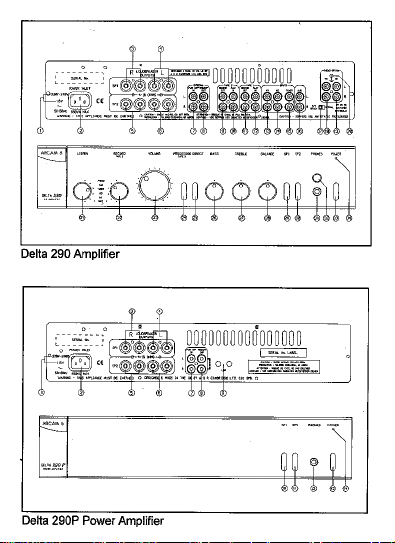
DELTA 290 AMPLIFIER/ DELTA 290P
& XETA 290P POWER AMPLIFIER
HANDBOOK
Page 2
Page 3

INTRODUCTION
This manual is in 4 pans:
1. This section has inibnnadon relevant to
both the Delta 290 and Delta 290P. This
includes Warnings and Cautions on use
and details of how to bi-wire your
loudspeakers.
2. D290 integrated amplifier operating
instructions.
3. D290P power amplifier operating
instructions. (The Xeta 290P power
amplifier has different fiont panel
graphics but is functionally identical).
4. Using the D290 & D290P together to bi
amp your loudspeakers.
N.B. Circled numbers eg ® refer to items on
the diagrams inside the flap of the fiont
INSTALLATION
® Check that your mains supply voltage
agrees with the voltage setting indicated
on the rear panel of the unit.
■ Ifyour mains supply volt^ is different,
consult your Arcam dealer.
MAINS SAFETY
■ This product is normally supplied with a
moulded mains plug already fitted to the
lead. If for any reason the plug needs to
it must be disposed of
be removed,
irrtmediately and securely, as it is a
potential shock hazard when inserted into
a mains socket.
■ Ifthe plug is removed then the remaining
lead must be rewired as follows:
■ The blue wire must be connected to the
terminal which is coloured blue or
marked with the letter
■ The brown wire must be coimeaed to
the terminal which is coloured brown or
marked with the letter L.
N.
The green and yellow wire must be
connected to the terminal which is
coloured green and yellow, or marked
svith the letter E or the safety earth
symbol.
When replacing the fuse in the supplied
moulded mains plug, the integral fuse
holder/cover must always be refitted.
Warning: This apparatus must be
SAFETY STANDARD
■ This product has been designed to meet
the lEC 65 international electrical safety
standard.
MAINS SUPPLY CONNECTIONS
® Insert the lEC line socket of the mains
lead fully into the power inlet on the rear
panel. Connect the other end to your
mains supply.
CAUTION: Your Delta 290 and D290P
generate heat when in use, particularly at higher
volumes. It is therefore most important never to
obstruct the ventilation slots on the top and
bottom of the unit as this will cause overheating.
If the temperature of the internal heatsinks rises
above a safe level, then a thermal cut out within
the amplifier will operate.
The POWER. LED on the fix>nt panel will turn
amber and the output protection relays will
temporarily remove the feed to the loudspeakers.
The system will reset itself as the heatsinks cool
Please note that under certain extreme
conditions it is possible for the Delta 290 or
D290P's thermal cut out to operate when
playing music at very high levels.
Page 4

If you hav« only one tape deck connect
it to the TAPE 1 sockets.
TAPE 1 KECORD OUT - Connect to
your tape deck's input (RECORD).
TAPE 1 PLAY IN - Connect to your
tape deck's output (PLAY).
TAPE 2 RECORD OUT - Connect to
your tape deck's input (RECORD) or to
your A/V processor's Tape or Line
TAPE 2 PLAY IN - Connect to your
tape deck's output (PLAY) or to your
A/V processor's Tape or Line outputs.
A/V - Suitable for connecting an
Audio/Visual produa such as a VCR,
Laserdisc player or Nicam tuner.
CD - For connecting your CD player or
DAC.
TUNER - For connecting your radio
tuner,
AUX - For connecting any unit with a
line level output, eg. tape deck, tuner etc.
PHONO OPTION-Please note: The
phono inputs are on a separate plug-in
module which your Arcam dealer or
distributor can supply and fit.
This module is compatible with most
high output moving coil and moving
magnet cartridges (MM) and low output
moving coil cartridges (MC).
MM or MC is selected via an internal
switch. Your cartridge type should be
specified when the module is fitted.
MM - For connecting a turntable fitted
with a h^ output moving coil or a
movir^ magnet (MM) cartridge.
® MC - For connecting a turntable fitted
with a low output movii^ coil (MC)
cartric^e.
@ GROUND TERMINAL - For
connecting your turntable's earth lead (if
fitted).
OPERATION OF THE DELTA 290
® NORMAL/A/V READY SWITCH-
With the switch set to NORMAL the
unit functions as a standard amplifier.
For use with A/V decoders with its own
volume control, such as the Arcam Xeca
2, set the switch to 'A/V READV. This
bypasses the Delta 290's volume control
when 'PROCESSOR/TAPE 2’ input is
selected, to provide a fixed gain
amplifier.
The volume control and MUTE cannot
be operated by remote in this situation.
© LISTEN SELECTOR-Selects the input
you wish to listen to. This s^al dso
goes to the TAPE 2 output sockets for
recording on a cassette deck or for
external processing The selector can also
be operated by remote control. (See
Remote Conaol Functions).
@ RECORD SELECTOR - Selects the
input you wish to record on TAPE 1.
This operates independently of the
LISTEN function.
@ VOLUME - Adjusts the volume level of
the loudspeakers and hea^hones. Note
that with the volume at minimum it may
be possible to still hear music very feintly.
This is normal.
VOLUME can also be operated by
remote control (See Remote Control
functions). I
Page 5

PROCESSOR/TAPE 2- This U a tape
loop to enable monitoring of a recording
on a 3 head cassette deck. It can also be
used to enable line inputs to be sent to an
external surround decoder such as the
Arcam Xeta 2 for proccssii^ before being
routed back to the amplifier.
For playback oía cassette deck or if using
an A/V processor attached to TAPE 2
press the button in.
Note: PROCESSOR/TAPE 2 is not
remote controllable.
DIRECT - Bypasses bass, treble and
balance controls. This affects all inputs,
and will generally pve a small
improvement in sound quality and a
useful reduction in the level of
background hiss.
BASS - Rotate clockwise to boost the
bass response and anti-clockwise to cut
the bass response. For a flat response
leave in the central 'click' position.
TREBLE - Rotate clockwise to boost
the treble response and and-clockwise to
cut the treble response. For a flat
response leave in the central 'click'
position.
BALANCE - Rotate clockwise or anti
clockwise to move the position of the
stereo image. This may be necessary ifit
is not possible to sit centrally between the
speakeis. In normal use leave in the
central 'click' position.
SPl - Selects or defeats the main pair of
speakers. Push the button in to select.
SP2 - Selects or defeats the secondary
pair of speakers. Push the button in to
select.
HEADPHONES SOCKET - Accepts
headphones rated between 8 ohms and
2kohms fined with a 6.3mm stereo jack
plug. Ifyour headphones are fitted with
a different plug contact your dealer for a
suitable adaptor. If you wish to listen on
headphones only, use SPl and SP2 (if
necessary) to mute the speakers.
The headphone socket is always switched
on, irrespective of the positions "of
svihtches 9 and ®.
REMOTE RECEIVER - Ensure the
remote receiver is not obscured or
commands from the remote control
handset will not be received.
POWER - Svntches the unit on and off
POWER LED - The LED above the
POWER switch will initially glow
amber. After a few seconds, it will ^ow
green. When the LED ^ows amber, the
speakers are disconnected and an internal
protection circuit is activated or the unit
has been muted by use of the remote
control. If this LED glows amber during
normal use it may be due to the amplifier
overheating or an output overload.
Check the amplifier is properiy
ventilated.
Switch the amplifier off and wait for 2-3
minutes before switching on again. If the
LED continues to glow amber, switch
the unit off. remove all the speaker
cables and switch on again. If the LED
goes to green upon switch on then check
the speaker and speaker cables for short
circuits before reconnecting them. If the
LED continues to glow anfoer with no
speakers connected contact your Arcam
Page 6

TAPE RECORDING
Both lets of upe sockets (TAPE 1 and
TAPE 2) are identical in sensitivity and
suitable for use with almost any type of
recorder (cassette, hi-fi VCR, reel to
reel, DAT. etc.).
RECORDING (TAPE 1): Any input
signal available on the Delta 290 may be
routed to the TAPE 1 output sockets by
using the RECORD selector to select
the appropriate input.
Set your tape recorder into its recording
mode and the selected input will be
recorded. Selecting the same input to
listen to will not affect the signal sent out
to the recorder and
to listen to the input being recorded.
You may listen to another input whilst
recording on TAPE 1 by use of the
LISTEN selector.
If your upe recorder is a 3 head design,
this will aDow A-B monitoring of the
actual recording while it is taking place.
Switching the listen switch between the
original source and TAPE 1 during
recording will then allow you to make a
true 'before and aftef (A-B) comparison.
PLAYBACK (TAPE 1): Set LISTEN to
TAPE 1 and set your tape recorder in its
playback mode.
RECORDING AND PLAYBACK,
TAPE 2: Proceed as above, except use
the TAPE 2 sockets and select the input
to be recorded by use of the LISTEN
selector. Use the PROCESSOR/TAPE
2 button when monitoring or playing
back the recording.
Do not move the listen selector whilst
recording or you will lose the signal.
TAPE TO TAPE DUBBING: The
Delta 290 aUows 2 way tape dubbing
(copying) from TAPE 1 to TAPE 2 or
wtII now enable you
For example, to copy from a recorder
connected to the TAPE 2 sockets to a
recorder connected to TAPE 1. first
switch the RECOPD selector on the
Delta 290 to TAPE 2. This routes the
TAPE 2 signal to TAPE I's output.
Then set the first tape recorder into its
'record' mode and the second to
'playback' mode to enable the transfer to
take place. If you wish to monitor the
transfer while it is taking place switch
LISTEN to TAPE 1.
To record from TAPE 1 to TAPE 2 set
listen to TAPE 1. To monitor push the
PROCESSOR/TAPE 2 button in.
PRE/POWER CONNECTIONS
® PWR AMP IN-To use your Delta 290
as a power amplifier, connect the output
of your pre-amplifier to PWR AMP IN.
Set the internal selector switch to EXT
INPUT position. Under these
circumstances it has exactly the same
specification and performance as a Delta
290P power amplifier. Contact your
dealer or Arcam for more deuils.
® PREAMP OUT - To use your Delta
290 as a pre-amplifier, connect
PREAMP OUT to your power
amplifier’s input.
Please note: the PREAMP OUT
sockets are peimanendy active.
REMOTE CONTROL FUNCTIONS
■ Your Delta 290 amplifier is supplied with
the Arcam CR25 "Handi Remote" infia-red
remote control handset, which has buttons
to allow the simple operation of other
products. It is supplied with 2AA batteries ensure these are inserted correctly.
Page 7

The remote allows you to operate the Delta
290 plus some basic functions of an Arcamt
or Philips based CD player, a remote
controlled tuner (such as the Arcam Delta
280*), the Arcam Delta Black Box 500
DACC and an Arcam ampUfier with remote
control 6icilicy( the Alpha 6/ Alpha 6 Plus,
Delta 110/1 lOS pre ampUfiers and the Xeta
One/ Two Home Cinema amplifiers).
Note: versions of the Delta 280 FM tuner
manufitctured before April 1995 will not
respond to the prograimne up/down buttons
on the "Handi Remote".
REMOTE MODE - The Delta 290 is fitted
with an internal Remote Mode selector
switch, which is factory-set to NORMAL.
In NORMAL mode, the Arcam "HandiRemote" or Arcam CR200 System Remote
will synchronise the operation of any Arcam
CD player or transport, cassette deck or
remote control tuner with the LISTEN
selector on the Delta 290, all at the touch of
a single button.
For example, using the remote in CD mode,
press PLAY, and the CD player will start the
disc and the LISTEN function selects CD,
If this fecility is not required, the internal
selector switch should be set to UNIQUE.
The LISTEN selector switch can still be
operated by either remote control handset.
The MUTE button mutes the speaker
connections and pre-amp outputs. Both
tape outputs however remain active. In
MUTE mode the power LED will rum
amber until mute is disabled by either
ptessir^ MUTE again or pressing volume
-/+.
t Except the Alpha One CD player, which uses a different remote control language.
Input selection may also be made via the
CR25 and CR200 remote control handsets.
Where fitted, the phono stage is selected
with the PHONO button. All other inputs
are made active when the relevant button is
pressed. TAPE 2 may be chosen via the
fiont panel switch but not by the remote
control handset.
Note: The SHIFT button does not initiate any
functions within the Delta 290/290P.
DELTA 290P POWER AMPLIFIER
Please refer to drawing inside front cover.
LOUDSPEAKER CONNECTIONS
■ The speaker terminals are colour coded red
for positive and black for negative. These
terminals are also labelled IL' for the ri^t
channel speakers and 'L* for the left channel
speakers.
Connect terminals ® to your right speaker
and terminals ® to your left speaker.
■ Connect the red cable termination to the red
terminals and the other cable termination to
the black terminal, ifyour speaker cable has
bare ends, the positive conductor can usually
be identified by a ridge or coloured markii^.
Ensure that no stray strands are allowed to
touch another cable or the amplifier's casii^.
This can cause a short circuit and damage
your amplifier!
®,® To drive a second pair of speaken, connect
terminals ® to the tight speaker and
terminals @ to the left speaker.
Page 8

The Delta 290P can drive two pairs of
loudspeaken, simultaneously if req^uired,
providii^ both pairs are raced between 8 and
16 ohms. Either pair can be selected using
the switches labelled SPl and SP2 on the
front panel. To avoid overheacii^, the
combined load impedance as seen by the
amplifier should not fall below 4 ohms per
channel.
CONNECTING YOUR SOURCE
COMPONENT
® PWR AMP IN -Connect to your pre
amplifier ouqsuts.
® PREAMP OUT: The 290P can be
connected to provide two mono outputs
from a single input. Using the U-link ®
supplied, cormect the PREAMP OUT
sockets ® together.
Utilising one Delta 290P per loudspeaker in
this maimer will allow bi-amplifying ofbiwireable loudspeakers. This is particularly
beneficial for top quality stereo installations
with a separate pre-ampUfier, or for the left,
centre and i^ht channel loudspeakers in a
five speaker Dolby Pro Logic system.
Contact your Arcam dealer for more
detailed information.
■ Daisy Chain - The Delta 290P is capable
of driving further Delta 290P amplifiers (or
any other power amplifier), to drive more
speakers (eg. those in other rooms or triamplified speaken etc). Connect the extra
power amplifier inputs to the PREAMP
OUT ouq>uts ® left to left, right to tight.
FRONT PANEL
SPl and SP2 - Pressing the SPl switch turns
on the speakers connected to the SPl
(upper) set of output terminals on the rear
panel. Similarly the SP2 switch turns on the
speakers connected to the SP2 (lower) set of
output terminals.
■ Both the SPl and SP2 switches can be
turned on at the same time, provided chat
the combined impedance of the two pairs of
speakers does not fall below 4 ohms per
charmel.
Important note: If both switches are turned off
then the amplifier will appear not to be
ftinctioning. as all speakers will be switched off!
® HEADPHONES SOCKET - Accepts
headphones rated between 8ohms and
2kohms fitted with a 6.3mm stereo jack
plug. If your headphones are fitted with a
different plug contact your dealer for a
suitable adaptor.
■ The headphone socket is always switched
on, irrespective of the positions of switches
® and ©.
® POWER - Switches the power on and off.
© POWER LED - This will initially ^ow
amber. After a few seconds, it will ^ow
green. When the LED gjows amber, the
speakers are disconnected and an internal
protection circuit is activated.
■ If this LED glows amber during normal use
it may be due to the amplifier overheating or
an ouqiut overload. Check the amplifier is
properly ventilated. Switch the amplifier off
and wait for 2-3 minutes before switching
Page 9

If the LED continues to glow amber, switch
the unit off, remove all the speaker cables
and switch on again. If the LED goes to
green on switch on then check the speaker
and speaker cables for short circuits before
recormecting them. If the LED continues CO
glow amber with no speakers connected
contact your Arcam dealer.
ADDING A DELTA 290P TO AN EXISTING DELTA 290
If you are usir^ a Delta 290, a Delta 290P can be
added to bi-amplify a pair of bi-wireable
loudspeakers. This will reap substantia]
improvements in sound quality if the following
precautions are observed.
Always switch on the Delta 290 and allow it
to stabilise (indicator l^t turns green)
before switching on the Delta 290P,
The Delta 290 and Delta 290P power
amplifier are placed on separate shelves.
Stacking the units on top of each other will
reduce the sound quality slightly. It will also
reduce ventilation and consequently the
power handling capability.
The exiscir^ Delta 290 should be used to
drive the loudspeakers' HF (high frequency)
units. The new Delta 290P is utilised for the
LF (bass) drivers, as shown in the wiring
diagram below.
At the end of a listening session the Delta
290P should always be turned off first.
High quahty interconnect cables should be
used between the Delta 290 and Delta 290P.
The use of high quality intercoimect and
speaker cables in your system is essential to
obtain good sound quality. Cables from the
AudioQuest range are ideal partners for
Arcam products. ContaCT your dealer for
further details.
WARNING - Ensure that the links
connecting the red terminals and the black
terminals on the speakers are removed
before switching on the amplifiers. Failure
to do this could cause damage to one or both
amplifiers and this is not covered under the
warranty.
Page 10

TECHNICAL SPECIFICATION
Delta 290P Power Amplifier
Output power (20Hz-20kHz at 0.5%THD)
Harmonic Distortion, 60W, 8Q at IkHz
Peak current rating
Input impedance
Input sensitivity
Gain (IkHz)
Frequency response
Noise (CCIR) ref. rated power
Mains voltage
Power consumption(max)
Size W/D/H mm.
Weight nett
packed
Supplied accessories
E & O E
70W, both channels, 8Q
-MOW, single channel, 4Q, IkHz
0.02% typical
±18 amps
7.5kQ
670mV for 75W/ 8Q
31.3dB±0.2dB
10Hz-20kHz ± 0.5dB
-lOOdB
230V/115V ±12%
550VA
430x300x92
6.0kg
7.0kg
Mains lead
PROBLEMS?
If your dealer is unable to answer any query regarding this or any other Arcam product
please contact Arcam Customer Services on +44 (0)1223 440964 or write to us at the
address on the back cover of this handbook.
Page 11

TECHNICAL SPECIFICATION
Delta 290 Ampllller
OutDut Dower (20Hz-20kHz at 0.5%THD)
Hannonic Distortion, 60W, 8£5 at IkHz
Peak current rating
Tone controls (typical variation)
L/R Crosstalk
INPUTS
Line inputs;
Noise (CC!R) ref! rated power
Input impedance
Overload tnaigin
A/V loop input (AA^ mode)
Input impedance
Power amp in
Input impedance
Phono board (if fitted):
Noise (CCIR) ref. rated power
Input impedance
Overload matgin
OUTPUTS
Preamplifier Output
Nominal output level
Maximum output level
Output impedance
Tape/ AUX outputs:
Output impedance
Headphones;
Maximum output level into 600Q
Output impedance
Mains voltage
Power consumption(max)
Dimensions W/D/H mm.
Weight nett
packed
Supplied accessories
E&OE.
VOW, both channels into 8Q
NOW, sin^e channel into 4fi, IkHz
0.02% typical
± 18 amps
± 5dB at lOOHz and lOkHz
-72dBatlkHz
Sensitivity 165mV
-99dB typical
4-7kfi
>50dB
Sensitivity 690mV
4-7kD
Sensitivity 670mV
7.5kfl
Sensitivity 2.6mV MM, 260icV MC
-79dB MM, -73dB MC
47kfl MM. 300ft MC
100ft
230V/115V ±12%
550VA
430x315x92
6-5^
7.71^
 Loading...