

Page 1
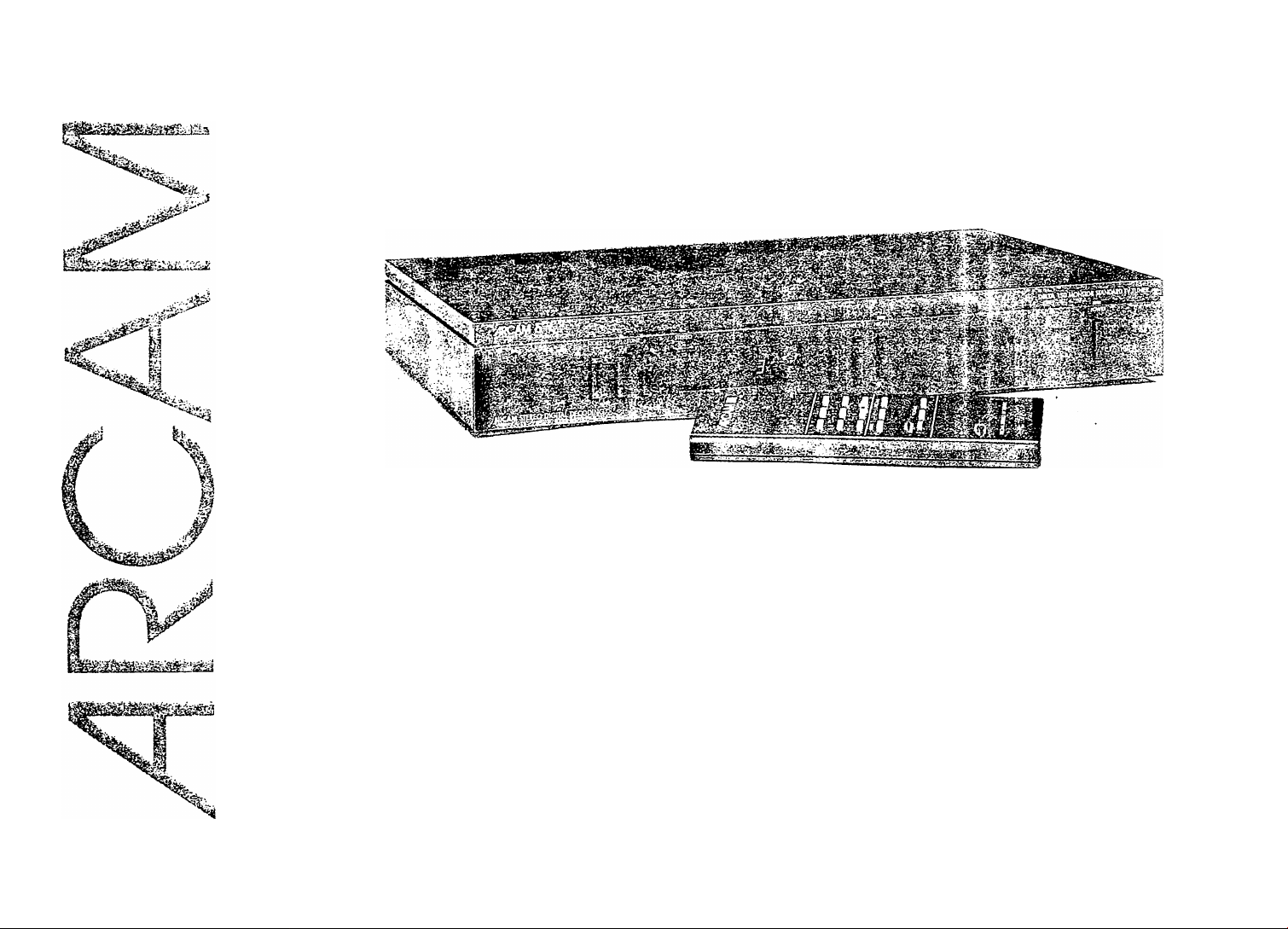
Audiophile products
from A&R Cambridge
Delta ISO MICAM stereo
TV toner handbook
Page 2

Addendum
The following points were omitted from the Delta 150 handbook:
The "MUTE" function on the CR50 remote control handset will only work when the "VARIABLE AUDIO OUTPUT" is
connected.
When switching the Delta 150 on from the "STANDBY" mode, the last selected channel number will
appear on the front panel display.
If the Delta 150 is switched on with the power switch on the front panel, It will default to channel 1.
When the Delta 150 is connected to your hi fi VCR using a SCART (or separate audio/video leads), it will be necessary
to switch the VCR to the "AUX" mode in order to record stereo transmissions.
Please refer to the VCR's handbook.
Page 3
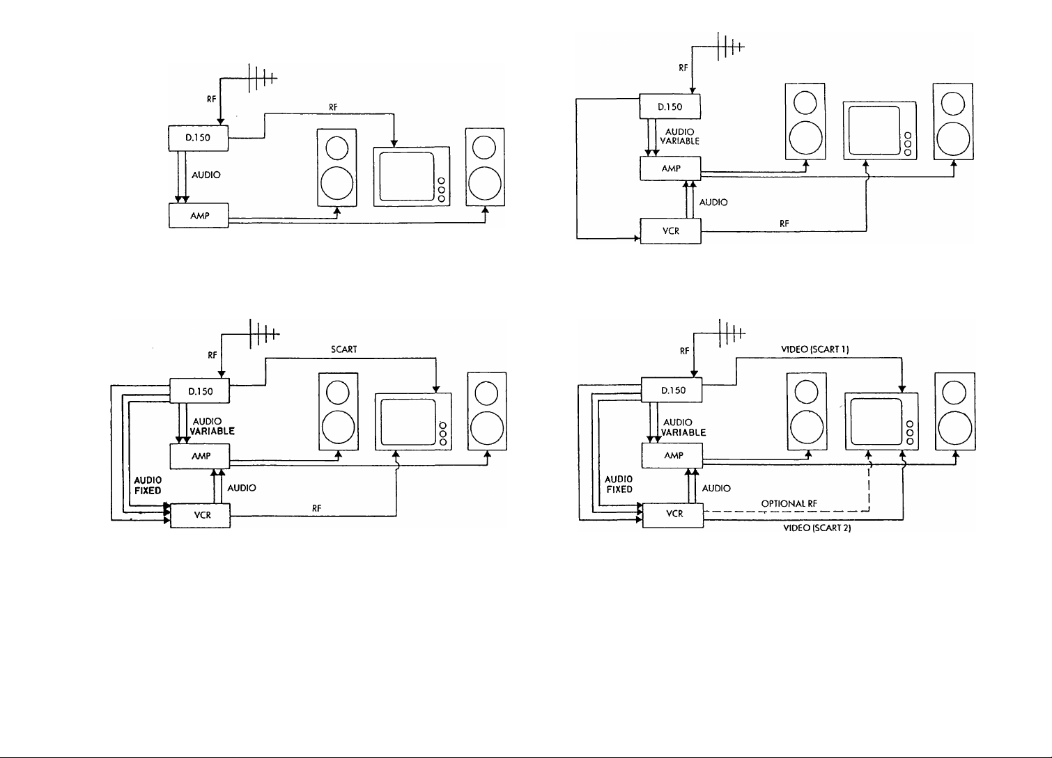
SCART
Figure I. Simple configuration using the Delta ISO's remodulated output
VIDEO
(BNC)
Figure 3. Configuration making use of TV set fitted with a SCART socket. Figure 4. Configuration making use of TV set fitted with two SCART sockets.
Figure 2. Simple configuration connecting your TV and VCR to the Delta 150.
VIDEO
(BNC)
Erratum
Please refer to these diagrams when Installing your Delta 150, NOT the diagrams on page 11.
These have been incorrectly labelled. Please accept our apologies for any inconvenience this may have caused.
Page 4

Delta 150 NICAM stereo TV tuner handbook
Introduction
The Arcam Delta 150 is a NICAM (Near Instantaneously
Companded Audio Multiplex) stereo TV tuner which offers the
enthusiast near compact disc quality stereo sound from terrestrial TV
broadcasts in the UK.
The Delta 150 is a stand alone unit built to the highest
standards. It is designed to be used in conjunction with a television or
video system, and complements the existing range of Arcam Delta
hi fi separates.
Although there are many 'stereo' TV sets currently available,
the quality of the TV's own speakers will not realise the full potential of
the Delta 150.
Best results will be achieved when the Delta 150 is
connected to an amplifier and a pair of good quality hi fi loudspeakers.
We recommend positioning your television set midway between your
speakers, and turning down the volume on the TV set. If your room
layout does not permit this, and your amplifier is capable of driving two
or more pairs of speakers, you might choose simply to place a second
pair of speakers either side of the TV and use these when watching the
television. Your main pair of speakers can then be left in their existing
location and used exclusively for the hi fi system.
The Delta 150 is also equipped with a high quality composite
video output. This can be used to enhance picture quality, provided your
TV has a suitable composite video input (usually found on a SCART or
Peritel A/V socket).
Because of its design, the Delta 150's 8 presets can be tuned
and operated in much the same way as a conventional TV set, either
from the unit itself, or via the supplied CR50 remote control handset.
This also provides remote control operation of the volume, mute, and
standby functions.
Please study this handbook carefully to ensure that you get
the best possible results from your Delta 150 NICAM tuner. It will
probably be necessary to refer to the handbooks of your video cassette
recorder (VCR) and TV in order to find the configuration that suits
you best.
If in doubt, consult your dealer. He is there to help!
Page 5

Delta J50 NICAM stereo TV tuner handbook
Installing and using your Delta 150 IMICAM tuner
Mains Supply
The Arcam Delta 150 is supplied to work on 220V/240V AC
mains. A detachable mains lead is supplied with the Delta 150. The cores
of this lead are coloured in accordance with the following code;
Green and yellow - Earth
Blue - Neutral
Brown - Live
If the colours in the mains lead do not correspond with the
coloured markings identifying the terminals in your plug, proceed
as follows;
The wire which is coloured green and yellow must be
connected to the terminal on the plug which is marked by the letter E, or
to the safety earth symbol, or to the terminal coloured green and yellow.
The wire which is coloured blue must be connected to the terminal
which is marked by the letter N, or coloured black or blue. The wire
which is coloured brown must be connected to the terminal which is
marked by the letter L, or coloured red or brown.
Fuses
If the mains plug is fused, fit a 3 amp fuse.
The AC supply inlet to the Delta 150 uses a standard lEC
chassis mounting plug.
The lEC line socket on your mains lead and the lEC plug on
the Delta 150 are a tight fit; before first using the Delta 150 it is therefore
important to ensure that the socket is firmly pushed home into the
chassis plug.
Under no circumstances should the Delta 150 top cover be
removed unless the supply is first disconnected at the wall socket.
Notice
1. Please retain the carton and all packaging materials
provided with this equipment so that it may be repacked correctly
if it ever becomes necessary to transport the unit, or to return it
for service.
2. If servicing is required, then the equipment should be
properly packed and returned to the dealer from whom it was
purchased. It is essential to include a covering letter giving your
name and address, and a brief but thorough description of
the fault.
Positioning the Delta 150
In general we believe you will find the Delta 150 to be most
useful if it is placed alongside your hi fi equipment rather than your
television. The various audio cables required can then be kept short, to
ensure the highest sound quality. If you own a hi fi video cassette
recorder, there is also a strong case for moving this closer to your hi fi
system. The VCR's audio record and replay functions are then more
easily integrated with the Delta 150 and the rest of your sound system.
Connected to your FM radio tuner, most hi fi VCRs can be used to record
long duration radio programmes if you wish.
Please observe the following precautions when siting the
Delta 150:
Do not place the Delta 150 close to a source of heat (e.g.
direct sunlight, a radiator or a powerful amplifier)
Ensure that air can circulate freely around the unit.
Do not place the Delta 150 directly underneath (or on top of)
a turntable, cassette deck or VCR. The mains transformer of the Delta
150 may, in some circumstances, induce a level of background hum into
the sensitive circuits of these units.
Do not expose the Delta 150 to rain or moisture.
Page 6

Delta 150 NICAM stereo TV tuner handbook
Connections and warming up
There are several points that should be noted before using
your Delta 150.
In particular, it is advisable to switch off your system before
connecting it up to the Delta 150. This will avoid possible damage to
your loudspeakers. At the very least, ensure that the volume control on
your amplifier is turned down, or an unused input is selected.
Although the Delta 150 will receive broadcasts within
seconds of switching on, in common with other audiophile products its
internal circuits take some time to fully stabilise. We have found that the
very best sound quality may not be obtained until the unit has had some
time, maybe an hour or two, to warm up.
Note
When the Delta 150 is switched to standby mode, these
critical circuits remain energised. The optimum audio performance may
then be obtained as soon as the unit is switched on again.
Page 7

Deita 150 NICAM stereo TV tuner handbook
Rear panel connections
The Arcam Delta 150 NICAM stereo TV tuner is equipped
with numerous inputs and outputs to ensure compatibility with other
audio and video equipment. It has also been designed so that it can be
used in many different configurations. Please refer to the diagrams on
page 1 1.
The rear panel connections are as follows;
Audio outputs
Two pairs of audio outputs, one fixed and one variable, are
provided via RCA phono connectors. These sockets are marked 'L' for the
left channel and 'R' for the right channel, with the left channel sockets
nearer the top of the cabinet. Your connecting leads will be marked
either 'L' or 'R', or will have a red plug for the right channel, and a black
or white plug for the left channel.
The audio output should be connected to your amplifier's
A/V or AUX inputs, or to the audio input of your hi fi VCR using the
supplied phono lead.
The very best sound quality will be obtained by using the
fixed outputs. However, by using the variable output, you can take
advantage of the remote volume facility on your handset. If you are
connecting the Delta 150 directly into your VCR, we recommend the use
of the direct output, in order to avoid inadvertently adjusting the
volume level when recording a programme.
Both pairs of audio outputs may be used simultaneously
if required.
SCART socket
This is a 21 pin socket, also known as a CENELEC, Peritel or
Euro connector It contains both audio and composite video (CVBS)
outputs, and a logic voltage (CVBS status) which is either OV (Delta 150
off or in 'standby' mode) or 12V (Delta 150 on). This can be used to
control the TV/AV switching function on certain models of TVs.
The output pins are connected as follows:
Pin 1 - Audio out, right.
Pin 3 - Audio out, left.
20
Pin 4 - Audio ground.
Pin 8 - Status CVBS.
Pin 17 - Video ground.
'++++‘M‘++++
Pin 19-CVBS out.
Pin 21 - Shielding.
Page 8

Delta 150 NICAM stereo TV tuner handbook
If you have a VCR, TV or A/V amplifier which is fitted with a
SCART socket, you can connect it to the Delta 150 using the appropriate
SCARTlead.
With a suitable hybrid lead, the outputs from the Delta ISO's
SCART socket may also be fed directly to the appropriate BNC or phono
sockets of a VCR, TV or A/V amplifier.
The Delta 150's remote volume facility may be assigned to
the SCART audio outputs by adjusting the small blue SCART audio
switch, located immediately to the left of the main audio output sockets.
For fixed outputs, use the tip of a ball point pen or pencil to push the
switch in; for variable outputs push the switch again so that it springs
back flush with rear panel.
Composite Video Output
The CVBS output is also available on a BNC socket as well as
the SCART socket described above. The two outputs may be used
together if required, for example to feed the composite video inputs of
both a VCR and a TV/monitor at the same time. Good quality 75 ohm
co-axial cable, or a specialist video cable, must be used for this purpose.
Note that teletext information is preserved on this output, but not
sound. In general the CVBS outputs will provide better video quality
than that obtained by using the remodulated RF output (see below).
Aerial input
This utilises a UK standard 75 ohm co-axial socket. Your
existing TV aerial lead, which is presently connected to your TV set or
VCR, should be connected to this input.
As with any audio or video system, the best results will only
be obtained with a good quality outdoor aerial, correctly oriented
towards the appropriate transmitter(s). To avoid unnecessary
degradation of the signal the aerial downlead must be UHF co-axial
cable of the very highest quality (such as low loss type RG59). We also
recommend against the use of aerial preamplifiers or distribution
amplifiers whenever possible, as these can often introduce more
problems, such as noise and cross-modulation distortion, than they
solve. Your local dealer or aerial contractor should be able to provide
suitable advice on all of these topics.
RF (aerial) output
The Delta 150 is equipped with a male co-axial RF output
socket similar to those used in VCRs. This performs two functions.
Firstly it provides a 'clean feed' of all the UHF TV channels
picked up by the aerial to other equipment further down the chain.
Therefore if the RF output is connected to the aerial inputs of your TV or
VCR, these units can be operated normally, independent of what the
Delta 150 is being used for. A suitable lead is provided with the Delta
150 for this purpose.
Secondly, the socket is connected internally to a remodulator
unit. This re-broadcasts, on or around channel 36, whichever TV station
is selected on the Delta 150 (n.b. The remodulated output includes the
video signal, with teletext and FM mono sound, but not NICAM sound).
If you tune your TV to the remodulated output channel, then
the Delta 150 can be used for normal selection of up to 8 channels of
sound and vision, either directly or via its CR50 remote control handset.
Note
The RF output does not work if the Delta 150 is turned fully
off. If it is left in the 'standby' mode, then the 'clean feed' circuit will be
operative. The remodulated output only functions when the Delta 150 is
switched fully on.
Page 9

Delta 150 fsJICAM stereo TV tuner handbook
Set up switch
The set up/normal switch works in the same way as on a
VCR, and is used to provide a test signal which helps tune in your TV or
VCR to the remodulated output of the Delta 150.
When the Delta 150 is installed, switch the power on and
select the 'set up' position on this switch.
Select an unused channel on the TV (eg channel 5), and
adjust the TV tuning until the test signal appears
on the screen - two white vertical bars on a black
background. The television should be tuned in to
give the best picture, i.e. good definition on the
edges of the white bars, and uniform brightness in
the centre of the bars.
Test signal
Now select the 'normal' position on the set up switch, and
tune the Delta 150, as described on page 8.
ADJ
If the test signal cannot be obtained properly when tuning
your TV into the remodulated output of the Delta 150, then it may be
necessary to adjust this screw. This will alter the channel (i.e. frequency)
on which the test signal is transmitted. Insert a small screwdriver
through the hole in the back panel and carefully make small adjustments
(about '/20 of a turn at a time) until a clear picture is received. The range
of adjustment is from channels 30 to 39.
It will probably be necessary to make this adjustment if you
use a satellite receiver as well as a VCR in conjunction with the Delta
150. In fact, it is possible that some re-adjustment of the channels
allocated to all these remodulated outputs may be necessary This is to
ensure that they do not interfere with each other or compromise the
reception of any TV transmissions broadcast within the range of
channels 30 to 39.
Power socket
Plug the supplied mains lead into the power socket, making
sure it is pushed firmly home.
Page 10

Delta 150 NICAM stereo TV tuner handbook
Front panel functions
DELTA 150 MONITOR STANDARD TV TUNER
STORE TUNE
V A
STEREO
LI L2 CHANNEL NICAM
l_l
I I
NICAM STEREO DIGITAL DECODING
Store and Tune buttons (up & down)
These controls are not for everyday use. They are needed to
tune the Delta 150 to the required TV channels in your area. By pressing
down one of the 'tune' buttons all the available TV channels from 21 to
69 are scanned in a period of approximately one minute, after which the
cycle repeats itself.
Most people will wish to assign BBC I to preset I on the
Delta 150, BBC2 to preset 2, ITV to preset 3 and so on. To do this
speedily when first setting up the Delta 150 proceed as follows:
Use the set up procedure described on page 7 to tune your
TV into the remodulated output of the Delta 150. Then use the TV
normally to check the programme content of a desired station (e.g.
Channel 4). Now use the Delta I50's channel buttons or remote control
to select preset number 4, shown by the display on the front panel.
Switch the TV back to channel 5 (displaying the Delta 150's remodulated
output), and hold down one of the tune buttons on the Delta 150 until
the same programme appears on the TV screen. When the picture is
tuned in as clearly as possible, press the 'store' button on the Delta 150.
Preset number 4 on the Delta 150 is now assigned to your local Channel
4 transmitter.
V Л
POWER
Repeat the procedure for as many other channels as you
wish, up to 8.
Please note that the Delta 150 employs a powerful
Automatic Frequency Control (AFC). This circuitry is used to compensate
for minor tuning drift with time and temperature. The AFC function is
defeated during tuning and remains defeated for approximately
1 second after a channel has been tuned.
The effects of this are noticeable as the Delta 150 will 'pull in'
a slightly mistuned programme back into the optimum position.
This means that it is possible to obtain a good picture on a
programme that is badly tuned in. When tuning the programme in, care
should be taken to ensure that the initial effects of the AFC are
minimised: this is done by tuning the programme in and waiting for
about I second for the AFC function to be enabled. If the picture does
not change when the AFC is enabled, then the programme will be close
to its optimum tuning point.
To achieve precise tuning you may find it helpful to use two
fingers to 'rock' between the tune up and down buttons. If this is done
quickly then the AFC remains disabled, making it easy to see when
optimum tuning (i.e. the best picture) has been achieved.
Page 11

Delta 150 NICAM stereo TV tuner handbook
Stereo LED
This LED (light emitting diode) will glow green when the
stereo flag is switched on at the transmitter. You may find that the stereo
LED will be illuminated even when a mono broadcast is transmitted. This
is not indicative of a fault, merely of the practice of the
broadcasting station.
LI, L2 Dual language mode LEDs.
The LI LED will glow green when a dual language
programme is transmitted. English is always transmitted as the main
language (LI j, and the second language is transmitted as L2.
The English language will be received automatically - there
is no need to select it. However, if you wish to receive the second
language, simply press the NICAM button once and the second
language will be received instead.
The L2 LED will now glow green.
Pressing the NICAM button a second time will return the
programme to L1. When a dual language programme is transmitted, the
stereo LED is not illuminated.
Note
When a dual language programme is transmitted, both
languages are in mono - although the chosen language will
automatically be heard through both loudspeakers of your TV or
hi fi system.
It is not possible to receive English on the left channel and
the second language on the right channel simultaneously.
Channel buttons
These two buttons select any of the 8 preset channels by
pressing the up Button to change sequentially from channels 1 to 8, and
the down button to change sequentially from channels 8 to 1.
NICAM button and LED
The NICAM LED uses a 'traffic light'sequence to indicate the
status of the sound track of the programme being transmitted.
If the LED glows red, only a mono FM programme is being
transmitted. This is automatically routed equally to both the left and
right audio outputs.
If the LED glows amber, a NICAM encoded programme is
being transmitted, but the tuner is switched to mono FM reception.
Press the NICAM button once and the LED will now glow green, to
indicate that the NICAM version of the transmission is being routed to
the audio outputs.
Press the NICAM button again to revert to the mono
FM mode.
Only if the LED glows green, are you receiving and listening
to a NICAM broadcast.
Tuning tip
When tuning in the channels of your Delta 150, please
observe the status of the NICAM LED.
If it glows amber, press the NICAM button before pressing
the store button, so that the NICAM LED now glows green.
This will ensure that every time this channel is selected, it will
be automatically received in NICAM (when transmitted).
Similarly, if a programme, which was originally available only
in mono FM (red LED), is now available in NICAM, you may find that
every time this programme is selected, the NICAM LED glows amber If
this is the case, simply press the NICAM button, so that the LED now
glows green, and then press the store button.
Power switch
This switches the unit on and off. The LED above the switch
will glow green when the unit is on.
Page 12

Delta 150 NICAM stereo TV tuner handbook
Remote control handset
The Delta 150 is supplied with the CR50 remote control
handset. It is powered by 4 x manganese alkaline AAA cells (supplied),
which are inserted in the base of the handset. To access the battery
compartment, slide the whole bottom panel forwards approximately
5cm (2 inches).
Take care to insert the batteries the right way round. We
recommend that the batteries are removed from the handset if the unit is
not to be used for some time.
Remote functions
The CR50 allows remote operation of the volume, mute,
standby, audio mode (NICAM or FM) and channel change functions.
Pressing the volume + button increases the volume.
Pressing the volume - button reduces the volume.
The system takes about 10 seconds to go from minimum to
maximum volume or vice versa. When the Delta 150 is first turned on,
the volume level is automatically set for a quiet listening level, i.e. about
30 dB below the maximum output.
Pressing the mute button mutes the audio output fully.
Pressing the mute button a second time restores the output. This is
particularly useful for answering the phone, or when the door bell rings.
Pressing the NICAM button selects the audio mode, either
FM or NICAM. Pressing the NICAM button when a dual language
programme is transmitted selects either LI or L2.
Pressing one of the 8 channel preset buttons selects the
desired channel directly.
Pressing the standby button puts the Delta 150 into the
'standby' mode. The audio, video and remodulated RF output signals are
muted and all LEDs are extinguished except the power LED. Pressing the
standby button again restores all functions to their pre-standby status.
The CR50 handset has a range of about 5 metres, and should
always be pointed towards the centre of the unit. Take care not to
obstruct the remote receiver (located next to the channel number LED),
or the tuner will not receive the handset's commands.
When using the handset, hold each button down for about 1
second. Do not attempt to press more than one button at a time.
Note
1. If the remote control becomes lost or accidentally
disabled, it is possible to remove the Delta 150 from its 'standby' or mute
modes by briefly switching the unit off and on again with the mains
power switch.
2. The two unmarked buttons on the CR50 have
no function.
Connecting cables
When dealing with high quality hi fi components, such as
those with the resolving power of the Delta 150, the question of
connecting cables becomes of paramount importance: We strongly
recommend that only first class interconnect cables are used, such as
those from the AudioQuest range. Detailed information on the
AudioQuest range of video and audio interconnect cables can be
obtained from your dealer, or the factory.
As a rule of thumb, you might consider budgeting to spend
between 5% and 20% of the cost of your system on cable. Surprising
though it may seem, this can be one of the most effective upgrades you
can carry out.
We suggest that you discuss the matter of video and audio
interconnect cables (and loudspeaker cables) with your dealer.
10
Page 13

Delta 150 NICAM stereo TV tuner handbook
Typical A/V system connections incorporating the Delta 150
RF
Figure I. Simple configuration using the Delta ISO's remodulated output
RF
Figure 3. Configuration making use of TV set fitted with a SCART socket.
11
Figure 2. Simple configuration connecting your TV and VCR to the Delta 150, using
remodulated outputs.
RF
Figure 4. Configuration making use of TV set fitted with two SCART sockets.
Page 14

Delta 150 NICAM stereo TV tuner handbook
Faults and their likely causes
IMo picture or sound. Check that;
1. the unit(s) are turned on and plugged into working
mains outlets.
2. the Delta 150 is not in the 'standby' mode (all lights off
except the green power LED). If so, press the standby button on the
remote control, or briefly switch the unit off and on again with the
power switch on the right side of the front panel.
3. your Delta 150 and/or TV has stored the TV
station correctly.
4. the chosen TV station is broadcasting at the time.
Picture OK, but no sound. Check that;
1. the Delta 150 is not in the mute mode. If so, press the
mute button on the remote control, or briefly switch the unit on and off
again with the mains power switch.
2. the variable audio output of the Delta 150, if in use, is
turned up (use the remote control).
3. the amplifier is switched on, set to the correct input and
that the volume is turned up.
4. the audio leads between the Delta 150 and your amplifier
are properly connected.
5. the loudspeakers are connected correctly.
Sound from one channel only. Check that.
1. the balance control on the amplifier is positioned centrally.
2. the audio leads are fitted correctly, and the wiring is not
faulty. Check by interchanging left and right leads.
3. both loudspeakers are connected correctly to the
amplifier's output terminals.
Sound OK, but no picture. Check that;
1. your TV set is selecting the correct channel.
2. if using SCART - SCART lead (Eurocable), the external
input has been selected on the TV/VCR.
3. the video cables to the TV are plugged in and
connected correctly.
Sound OK, but poor picture. Check that;
1. all the aerial (RF) plugs are pushed home firmly in their
sockets and are correctly fitted to their co-axial cables. If the outer
braiding (earth) of the cable is allowed to come into contact with the
central core of the cable, or the centre pin of the plug, this will result in a
very poor picture.
2. mutual interference is not being caused between TV
stations broadcasting between channels 30-40 and the remodulated
outputs from the Delta 150, VCR ora satellite receiver Careful retuning
of some or all of the remodulators fitted to these devices may be
necessary to effect a cure.
3. patterning of an otherwise clear picture may be caused by
(2) above or by cross modulation distortion in the tuner head of your
Delta 150, VCR or TV This is due to excessive signal levels and may
usually be controlled with simple in-line co-axial attenuators fitted in the
aerial leads between the units.
4. persistent hues near the corners of your TV picture may be
caused by your hi fi speakers being too close to the TV screen. The
speakers' powerful magnets affect the colour purity of the TV tube.
Move the speakers further away and turn the TV on and off again in
order to activate its degaussing circuits until the problem is solved.
Picture OK, but interference (crackling) on
NICAM sound
The NICAM digital signal is very robust and can normally be
received cleanly, even with a weak signal which gives an unacceptably
noisy picture.
12
Page 15

Delta 150 NICAM stereo TV tuner handbook
However, the NICAM signal is susceptible to adjacent
channel interference. This is a particular problem when trying to pick up
a distant NICAM TV transmission in the presence of a strong local
transmitter which uses similar channel numbers. The problem manifests
itself as a severe crackling on the NICAM sound channels. FM sound is
unaffected, and in severe cases the Delta 150 will switch back
automatically from NICAM to FM sound as the NICAM signal degrades.
There is no cure for this except to null out the interfering
signals. Careful re-orientation of your aerial may help as may a more
directional aerial array. If in doubt consult your local aerial contractor.
Further information on the availability of NICAM broadcasts
may be obtained from;
Independent Broadcasting Authority
Engineering Information
Crawley Court
Winchester
Hants
S021 2QA
Telephone 0962 822444
(see also ORACLE, p 697)
and
British Broadcasting Corporation
Engineering information Department
Broadcasting House
London
WlA lAA
Telephone 071 580 4468 Extension 5040
13
Page 16

Delta 150 NICAM stereo TV tuner handbook
Arcam Delta 150 NICAM Decoder
RF
OUT
VIDEO/AUDIOOUT
AUDIO OUT
14
© A & R CAMBRIDGE LTD 1990
Page 17

Delta 150 NICAM stereo TV tuner handbook
Technical specifications
Suitable for CCIR TV system I (UK)
RF input
Frequency range 471.25 - 855.25 MHz (Channels E21 - E69)
Impedance 75 Ohms
Input signal for onset of video noise 50dBuV
NICAM drop-out point 28dBuV
Maximum input signal 75dBuV
Locked picture and sound 20dBuV
RF system characteristics
AFC hold in -F/- 1.25 MHz
AFC pull in +/- 1.25 MHz
UHF modulator/booster
Boost gain 0 dB +/- 3 dB
Carrier frequency 543.25 - 615.25 MHz (E30 - E39)
Carrier level 73dBuV +/- 3dB
Test signal 2 vertical bars, line sync, only
IF section
Employs dual surface wave filter
Vision frequency 39.5 MHz
FM sound frequency 33.5 MHz
FM mono audio
Frequency response 40 Hz - 12 kHz 4-/Signal to noise ratio 70dB CCIR
De-emphasis 50uS
NICAM audio
Frequency response 30Hz- 14kHz +!- IdB
THD, NICAM OdB reference 0.02%
Signal to noise ratio 83 dB CCIR
De-emphasis CCIR J17
Channel balance +/- IdB
Dimensions
Width 430mm
Height 64mm
Depth 265mm (excluding rear panel connections)
Weight
Net 3.1 kg
Packed 4.5 kg
2dB
Video section both SCART and BNC outputs
Output level 1V peak to peak into 75 Ohms
Output impednce 75 Ohms
Audio section
Minimum load 5kOhms
Nominal output level 500mV
15
Page 18

Delta 150 NICAM stereo TV tuner handbook
Guarantee for UK sales
This equipment has been fully tested and a full record of
these tests made before despatch from the factory. Both the
workmanship and the performance of this equipment are (except as set
out below) guaranteed against defects for a period of two years from
the date of purchase, provided that it was originally purchased from an
authorised UK dealer under a consumer sale agreement. (The words
'consumer sale' shall be construed in accordance with Section 15 of the
Supply Of Goods (Implied Terms) Act 1973.)
The manufacturers can accept no responsibility for defects
arising from accident, misuse, abuse, wear and tear, neglect or through
unauthorised adjustment and/or repair, neither can they accept
responsibility for damage or loss occurring during transit to or from the
person claiming under this guarantee.
This guarantee covers both labour and parts, and is
transferable to subsequent purchasers, but the liability of the
manufacturers is limited to the cost of repair or replacement of the
defective parts (at the discretion of the manufacturers) and under no
circumstances extends to consequential loss or damage.
Claims under this guarantee
This equipment should be packed in the original packing and
returned to the dealer from whom it was purchased or, failing this, to any
other authorised Arcam dealer. If it is not possible to return the
equipment by hand, then it should be sent carriage prepaid by a
reputable carrier
If the original packing is not available, replacement packing
can be purchased from the manufacturers. The equipment should not be
sent by post.
Do NOT CONSIGN THE EQUIPMENT TO ArCAM UNLESS YOU HAVE BEEN
SPECIFICALLY REQUESTED TO DO SO BY THE MANUFACTURER'S TECHNICAL SALES OR
SERVICE DEPARTMENTS. DO NOT UNDER ANY CIRCUMSTANCES ATTEMPT TO
DISASSEMBLE THE EQUIPMENT BEFORE DESPATCH.
If you have any difficulty complying with these requirements,
please contact the manufacturers at the following address:
ARCAM (A & R Cambridge Limited)
Pembroke Avenue,
Denny Industrial Centre,
Waterbeach,
Cambridge, CBS 9PB, England.
Telephone (0223) 861550 and (0223) 440964
Fax(0223)863384
In either case you should state clearly your name and
address, the date and place of purchase together with a brief description
of the fault. In the event of equipment being returned which, after
having been tested, is found to comply with the published specification,
the manufacturers reserve the right to charge a reasonable fee for
testing the equipment, and for the return carriage.
Enquiries
The manufacturers are happy to answer any queries you may
have regarding the use of this equipment on the condition that this
enquiry is by letter and a stamped addressed envelope is provided. You
should state clearly the serial number of the unit, the dealer from whom
it was purchased, and the date of purchase.
This guarantee in no way varies or removes a purchaser s
STATUTORY RIGHTS.
Part No. SH034 JULY 1990 E&OE.
Designed by Carrods Design and Communications, Cambridge.
16
 Loading...