

Page 1
The A60+ Amplifier
A<
Owner’s Handbook
A & R Cambridge Ltd.
Page 2

Contents:
Introduction
Installing and using your A60+ 2
Technical details 7
Specification 10
Guarantee for UK sales
Back panel connections
Front panel controls 4
Tape recording
Spares kit 7
Connector wiring
Fdses
Removal of wooden cover
Cartridge loading modules 9
MC60 moving coil pre-amplifier
System block diagram
Inputs 10
Outputs 10
Performance
Typical performance graphs
11
12
13
1
2
6
7
8
9
9
9
Page 3

Introduction
The A60+ integrated stereo amplifier has been designed to provide high quality sound
reproduction and to blend unobtrusively with domestic surroundings.
The amplifier has four switchable inputs accepting signals from a turntable (fitted with a moving
coil or magnetic cartridge), a tuner, a Compact Disc player and either a cassette or reel to reel
tape recorder. It provides outputs for a pair of loudspeakers and for headphones, and low level
signals suitable for recording on to cassette and open reel tape. Additionally, in the A60AP+,
the pre and power amplifier sections may be split to permit more complex systems (e.g. using
ambisonics) to be assembled.
Although designed for simplicity of operation the A60+ has comprehensive tone control facilities
which enable good results to be obtained with a wide variety of programme material.
Please study the manual carefully to ensure that you get the best results from your amplifier.
Remember your dealer is there to help you. He has full technical and service information for all
A&R Cambridge products and considerable experience of their use in a variety of systems. If,
however, he is unable to answer your query then do not hesitate to contact us directly.
Page 4
Installing and using your AGO +
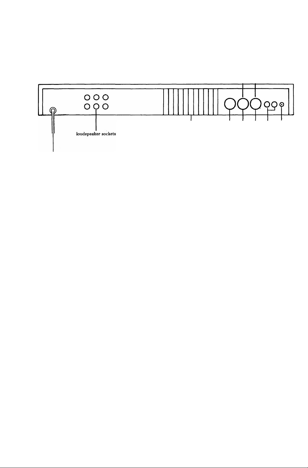
Back panel connections
A60AP+ IaP tuner and j
Model only I socket C.D. inputs
tape tuner
heat sink
mains cable inlet
\ compact disc disc
------1------
input sockets
Mains supply
The amplifier is normally set up for use with a nominal 240 volt 50/60 Hz supply. It can be
modified for a nominal 220 or 120 volt supply by your dealer or by the manufacturer.
The mains lead should be terminated with a three pin (earthed) plug fitted with a five amp fuse.
A 1 amp anti-surge mains fuse is fitted internally. It is recommended that the supply to the AGO
be disconnected when the amplifier is not in use.
UNDER NO CIRCUMSTANCES SHOULD THE AMPLIFIER COVER BE REMOVED
UNLESS THE SUPPLY IS DISCONNECTED AT THE WALL SOCKET.
Do not put excessive strain on the mains cable fixing either at the amplifier or at the plug.
Loudspeakers
The outputs are suitable for driving loudspeakers of 8 ohms nominal impedance or higher.
“4-8 ohm” loudspeakers, when marked as such, may also be used. “4 ohm” loudspeakers may be
used if care is taken not to operate at very high levels.
The loudspeaker terminals, will accept either wires or 4mm plugs. The upper set of three
terminals is for the left hand speaker, and the lower set for the right hand speaker. One side of
your speaker (normally the - side) should be connected to the black terminal; the other (the
+ side) may be connected either to the red (direct) or to the white (switched) terminal. When
the “direct” output is used loudspeakers and headphones may be used together; when the
“switched” output is used, insertion of a jack plug into the headphones socket will automatically
mute the loudspeakers.
ground
terminal
The A60+ is unconditionally stable and suitable for use with all types of loudspeaker leads,
including the “high definition” types.
Heat sink
The heat produced by the amplifier is dissipated into the air by the heat sink, which will, along
with the surrounding panel, become warm while the amplifier is on. The whole back panel may
become quite hot if the amplifier is run near full power. THIS IS PERFECTLY NORMAL.
However, if it becomes too hot to touch, switch off the amplifier at once and consult your
dealer.
Page 5

Disc input
The output lead from your turntable should be plugged into the disc input sockets. To prevent
hum pick-up in this very sensitive input, the cable must be screened and kept well away from
mains wiring. If the turntable has a separate earthing lead connected this should be attached
firmly to the amplifier’s ground terminal.
The disc input is normally suited to moving magnet or “high output” moving coil cartridges. If a
“low output” moving coil cartridge is to be used an additional internal plug-in pre-amplifier, the
MC60, must be fitted (see page 9).
The disc input impedance can be user adjusted over a wide range by fitting the (optional)
ULM/M or ULM/C plug-in loading modules for moving magnet and moving coil cartridges
respectively. However, most cartridges will perform satisfactorily without any loading module
fitted (see page 9 for further details of cartridge matching).
Tuner input
The tuner input is suitable for use with almost any AM or FM tuner or radio.
C.D. input/auxiliary output
The C.D. (Compact Disc) input will accept any other signal, but is particularly suitable for use
with a Compact Disc player. This socket also provides an output for recording onto a second
cassette or reel to reel tape recorder (see page 6).
There is no C.D. socket on the A60AP+ as it is replaced by the “AP” socket (see below). The
C.D. input is retained and is accessible via the spare pins of the tuner socket (see page 7). The
auxiliary recording output is not available on the A60AP+.
AP socket
(pre-amplifier output/power amplifier input - A60AP+ model only)
The A60AP+ has the facility for the user to split the pre and power amplifiers into separate
units. This allows signal processors (e.g. grapldc equalisers) to be inserted into the signal path
or more complex systems such as ambisonic (surround sound) systems to be built up.
When the pre/power amplifier split facility is not required the DIN shorting plug (supplied with
the A60AP+) should be inserted into the AP socket as this links the pre and power amplifiers
together so that the unit functions as a standard A60+.
Tape input/output
The tape input is designed to suit most cassette and reel-to-reel tape recorders and provides
both input and output, with A/B monitoring facilities (see page 6).
Page 6

Front panel controls
Mains power
The amplifier is turned on by the mains power switch (see illustration). It is good practice to
turn the amplifier off when it is not in use. ^
LED indicator light
This indicates that the d.c. power supply in the amplifier is operating. It will continue to glow
for a short time after the amplifier has been switched off as the d.c. voltage decays.
Input selection
The “disc”, “tuner” and “C.D.” switches are used to select the programme routed to the
loudspeakers. By pushing any one of these buttons, you will cancel the previous setting.
DO NOT attempt to push more than one button at the same time.
Tape monitoring facility
The tape monitor switch is generally left in the “off’ position (switch out), so that the
programme selected by the input switches is routed to the loudspeakers. When the tape button
is pushed, the recorded signal from the tape recorder is routed to the loudspeakers. Further
details of the tape monitoring facility may be found on page 6.
High frequency filter
When the filter switch is pushed in treble signals above approximately 7.5kHz are progressively
reduced. This is extremely useful for minimising unwanted hiss from noisy tapes or poor radio
reception. Under such conditions, use of this filter is generally better than simply turning down
the treble control.
Mono switch
The amplifier is in its normal mode when the mono switch is out. In this position, the left and
right input signals are amplified independently to appear at the corresponding loudspeaker
outputs. When the mono button is pushed in, the left and right signals are mixed together and
the combined signal is routed to both loudspeakers. The signals sent from the amplifier to
external tape recorders, via the “tape” and “aux” sockets,' are also blended into mono when the
switch is in.
Volume control
The volume control adjusts the listening level on both loudspeakers and headphones.
Page 7

NOTE; that each of the treble, bass and balance controls has a “click stop” in the dead centre
(12 o’clock) position, to enable a flat frequency response and even channel balance to be set
accurately and repeatably.
Treble control
The treble control progressively cuts treble signals when turned anti-cldckwise and boosts them
when turned clockwise. A “flat” frequency response is obtained when the control is set
accurately to the 12 o’clock position. It is unusual to have to use this control at its extremes, i.e.
outside the 9 o’clock or the 3 o’clock positions.
Bass control
The bass control progressively cuts bass signals when turned anti-clockwise and boosts them
when turned clockwise. Again, the flattest response is obtained at the 12 o’clock position. The
bass control in the A60+ amplifier has been designed to operate at frequencies about an octave
lower than normally encountered in other amplifiers. Because of this, a significant amount of
boost or cut may be employed to compensate for loudspeaker deficiencies without affecting the
lower middle frequencies.
Balance control
The balance control is used to move the stereo sound image to the left or right. It can be used
to compensate for imbalances in room acoustics or input signals.
Headphones socket
The headphones socket accepts any headphones fitted with a standard Vi inch stereo jack plug.
The headphones may mute the loudspeakers, or not, as required (see page 2).
Page 8

Tape recording
Any tape recorder, whether cassette or reel-to-reel, may be connected to the “tape socket” and,
if two recorders are to be used, the second model may be connected to the“C.D. input/auxiliary
output” socket.
Tape recording using the “tape” socket
The tape socket is designed for use particularly with three-head cassette or reel-to-reel
machines, although it is also perfectly suitable for use with two head machines. It is intended to
be connected to the “Une” inputs/outputs of these machines, which are usually accessed via
phono sockets.
To record, the programme source is selected by the “disc”, the “tunei^’ or the “C.D.” button.
This programme will automatically be sent to the recorder (at 5k ohm impedance). The signal to
be sent to the loudspeakers can then be selected by using the “tape” button: with this button
out, the selected programme source is sent to the loudspeakers. With the “tape” button pushed
in, the programme being received from the tape recorder will be sent to the loudspeakers; in the
case of a three head machine in “record” mode this will be the programme that is in the process
of being recorded from the amplifier. Hence instant “A-B” comparison is possible between the
original and the recorded signals. The replay level is adjustable in the A60-f by two
screwdriver-adjustable controls accessible from inside the amplifier,
N.B. None of the amplifier controls (apart from the input selector switches) affect the signal
being recorded.
To record in mono, on either a mono or stereo recorder, push the “mono” button before starting
to record. Again, the signal being recorded is not affected by the amplifier controls (apart from
the input selectors).
To replay via the “tape’
mode.
socket simply push the “tape” button and switch the recorder into play
Tape recording using the “C.D. input/auxiliary output”
socket (not applicable to A60AP+ model)
When a Compact Disc player is not plugged into the “C.D. input/auxiliaiy output” socket, then
a two head cassette or reel-to-reel tape recorder may be connected to this socket (A two head
machine is one without “A-B” monitoring, ie. replay-while-recording, facilities). To record, the
“tape” button is left in the out position and the signal to be recorded is selected by pushing
either the “disc” or “tuner” button. The selected signal will be sent tx> both the recorder (at 15k
ohm impedance) and to the loudspeakers. The signal should be routed to the line
inputs/outputs of the recorder, which are usually accessed via phono sockets,
DO NOT PUSH THE “C.D.” BUTTON WHILE THE RECORDER IS SWITCHED INTO
RECORD MODE AS THIS MAY CAUSE A FEEDBACK WHISTLE.
It is not possible to record from the “tape” input. If it is desired to record from a reel-to-reel
tape recorder onto cassette, then the reel-to-reel tape recorder should be plugged into the
“tuner” socket and the “tuner” button pushed.
To record in mono, on either a mono or a stereo recorder, push in the “mono” button before
starting to record.
N.B. None of the amplifier controls (apart from the input selector switches) affect the signal
being recorded.
To replay via the “C.D.” socket, switch the recorder to play mode and push the “C.D.” button.
The signal from the tape will then be sent to the loudspeakers. Due to the reduced sensitivity of
this input, playback will sound quieter than when using the “tuner” or “tape” inputs.
N.B. A licence may be required for recording from disc, radio or pre-recorded cassette.
Page 9

Technical details.
Spares kit
You are provided with a spares kit containing the following;-
• two red and two black 4mm plugs for loudspeakers
• one 5 pin DIN plug for input sockets
• two spare speaker fuses (1.6 Amp fast blow)
• one spare mains fuse (1 Amp anti-surge)
• one Allen key (A/F) which fits the screws in the control knobs.
Connector wiring - views from rear of plug as wired
A60 AP-I- MODEL ONLY
AP Socket
(5)
Disc
Tuner
L/R
Disc
Your turntable lead should be fitted with two PHONO plugs wired as illustrated. If any other
connector is fitted it should be removed and replaced by two PHONO plugs, or a high quality
adaptor lead used to interface.
LR
&om replay
output or
C.D. player
Tape and C.D.
Power
Amplifier amplifier
Input Output
Pre-
Tuner Socket
Input Input
Tuner
A standard 5 pin 180° DIN plug to 5 pin 180° DIN plug lead such as A & R lead type LOl
should be used for connection to a tuner with a DIN socket output, or a 5 pin 180° DIN plug
(pins 3 & 5) to two PHONO plugs lead for a tuner with a PHONO socket output.
C.D. input/auxiliary output
When connecting a Compact Disc player with a phono socket output, a 5 pin 180° DIN plug
(pins 3 & 5) to two PHONO plugs lead should be used. If the player is equipped with a fixed
lead terminated in two phono plugs then a high quality twin PHONO sockets to 5 pin 180° DIN
plug (pins 3 and 5) adaptor should be used (e.g. A & R lead type L02).
If a tape recorder is being used in conjunction with this socket, then the lead required here is
usually a 5 pin 180° DIN plug to 4 PHONO plugs (individually screened) type. If the recorder
also has a low level DIN input then a 5 pin 180° DIN plug to 5 pin 180° DIN plug (individually
screened) lead may also be used successfully in most cases.
Tape
A 5 pin 180° DIN plug to 4 PHONO plugs (individually screened) lead is required.
Tuner socket (A60AP+ model only)
In the A60AP-I- the auxiliary input is available at pins 1 and 4 of the tuner socket (see above). It
is accessible via the A & R type L04 “Y” adaptor lead which terminates in two line DIN sockets
for “tuner” and “C.D.” wired as the standard A60+’s “tuner” socket (see above).
AP socket
(pre-amplifier output, power amplifier input - A60AP+ model only)
The connections to this socket are shown above. The leads required will depend upon the
application, but when used with the SA60X for two way active crossover systems a 5 pin 180°
DIN to 5 pin 180° DIN crossover lead (e.g. A & R lead type L03) is required.
Loudspeakers
4 mm (banana) plugs or bare wires should be used, with connectors on the other ends of the
leads to suit your loudspeakers. It is important that the phasing of the loudspeakers is correct:
that is, the black or - terminal of each loudspeaker should be connected to the corresponding
black socket of the A60+ and the red or + speaker terminal to the red (for direct output) or
white (for switched output) socket. The upper sockets are for the left hand speaker and the
lower for the right. Do not make any connection between the left and right loudspeaker leads.
Page 10

Fuses
Loudspeaker fuses
These are 1.6 Amp (or less) fast blow 20mm x 5mm diameter fuses. They may blow if the
amplifier is:
- run continuously at high level into the correct loudspeaker load
- run at high level into a loudspeaker of too low an impedance (“4ohms” or less)
- run into a short circuit
They are user-replaceable and two spares are provided. However, if they blow consistently
without any of the above conditions obtaining please consult your dealer. DO NOT replace with
a fuse of greater value than 1.6 Amps (or wth a “slow blow” or “anti-surge” fuse) since this will
endanger the amplifier and your loudspeakers and invalidate your guarantee.
Power supply fuses
These are 3.15 Amp fast blow 20mm x 5mm diameter fuses. They are NOT USERREPLACEABLE and spares are not supplied. If these fuses blow, there is probably a fault in
the amplifier - do not change the fuses but consult your dealer.
Mains fuse
This is a 1 Amp anti-surge (slow blow) 20mm x 5mm diameter in all models. This fuse is
designed to protect against faults in the amplMer, transformer and mains switch. It is not
normally user-replaceable. However, should it blow during a continuous period of very high level
music, or on amplifier switch-on, it may be replaced once only WITH A FUSE OF THE
CORRECT TYPE (one spare is provided). If a second fuse blows within a short period then
there is a fault, and the amplifier should be returned to your dealer.
Location of MC60
moving coil cartridge
pre-amplifier
(optional)
Location of disc
input loading
module (optional)
D.C. supply fuses
NOT USER
REPLACEABLE
Loudspeaker fuses
1.6 Amp quick blow
DO NOT replace with
higher values or anti-surge
types
I----1 I I I Í I
_______________ ______ ______ ______
Mains fuse
1 Amp anti-surge
Removal of wooden cover
In order to inspect or change fuses, or adjust the tape replay level controls, you will need to
remove the wooden cover from the amplifier.
BEFORE REMOVING THE COVER, ALWAYS SWITCH OFF THE AMPLIFIER AND
DISCONNECT FROM THE MAINS SUPPLY.
Note that the mains fuse remains live whenever the amplifier is plugged into the mains, even
when the amplifier power switch is in the off position. To remove the cover unscrew the two
black-headed screws towards the rear of the side panels using a No.l “Pozidriv” screwdriver.
Tlien slide the cover forward as far as it will go (approximately 15mm) and lift it vertically
upwards. Replacement is merely a reversal of this procedure.
Page 11

Cartridge loading modules
These are purely passive modules designed to modify the input impedance of the amplifier in
order to obtain the best match with the cartridge in use. The ULM/M is designed for use with
moving magnet cartridges and the ULM/C (to be used in conjunction with the MC60 pre
amplifier board) is for use with moving coil types. Each is user adjustable via switches on the
module and offers the facility for additional components to be wired on to provide customised
loads.
The loading module should be plugged into the A60-I- in the position shown in the diagram
opposite.
DO NOT OPERATE THE LOADING MODULE SWITCHES WHEN THE AMPLIFIER IS
SWITCHED ON. THIS MAY DAMAGE YOUR AMPLIFIER OR YOUR LOUDSPEAKERS.
It must be emphasised that these passive modules mainly affect the sound balance and
frequency response. They will have little or no effect on the sensitivity of the amplifier except
with some moving coil cartridges where lower resistance loadings may reduce the cartridge
output significantly and necessitate a higher volume control setting.
Most cartridges will perform satisfactorily without any loading module.
MC60 moving coil pre-amplifier
The MC60 is designed for use with a wide range of “low output” moving coil cartridges. Its
input impedance is adjustable by using the ULM/C module as described above. To install the
MC60 the following procedure should be followed:
1 Switch off and disconnect the mains supply to the A60+ and remove all input and output
connections.
2 Remove the wooden cover (see above)
3 Remove the linking socket from the 8-way plug near the disc input socket (see diagram on
page 8) and retain this in a safe place.
4 Insert the MC60 board into the 8-way plug ensuring that all pins engage correctly and that
the board is in the correct orientation (see diagram on page 8).
5 Replace the wooden cover and re-connect as before.
In the SYSTEM BLOCK DIAGRAM:O the C.D. input is at 200mV nominal level and has additional h.f. filtering to remove unwanted ultrasonic signals
O the tuner and tape are at lOOmV levels and feed via the selector switch directly into the volume control
O the tape input, in addition, feeds via its own 100k ohm tape presets
O the disc input signal is amplified to lOOmV to feed via the selector switch directly into the volume control
O the mono switch has two functions: it monos separately the feed to the power amplifier and the feed to the tape and
aux outputs
Page 12

Specifications
All input sensitivities, nominal output levels and noise figures refer to 35 watts into 8il at
1 kHz. All noise figures are CCIR/ARM weighted ref IkHz. These specifications refer to both
the A60+ and A60AP+ except where stated otherwise.
Inputs
Magnetic cartridge
Sensitivity 2 mV
Overload Margin > 38dB 20Hz - 20kHz
Noise < - 70dB
Frequency Response better than +0.3dB - 0.5dB 40Hz - 20kHz
typically ± 0.2dB 70Hz - 20kHz, — 2.5dB at 20Hz
Input Impedance 47kil, in parallel with lOOpF
Switchable loading module available to provide the following additional loads: 30kQ, 8kil,
200pF, 320pF, 420pF and user programmable option.
Moving coil cartridge (MC60 board fitted)
Sensitivity lOOjLtV
Overload Margin > 38dB at IkHz
Noise < —63dB
Input Impedance 3300 in parallel with lOOOpF
Switchable loading module available to provide the following additional loads:
lOOO, 300, lOO, lOOnF and user programmable option.
Tuner
Sensitivity lOOmV
Overload Margin infinite
Noise < -85dB
Input Impedance lOOkO
Compact Disc
Sensitivity 200mV
Overload Margin infinite
Noise < -85 dB
Input Impedance 10 kO
Tape
Sensitivity variable via adjustable preset controls lOOmV-lOV
Noise < -85 dB
Input Impedance 47kO - lOOkO depending on sensitivity setting
Power amp (A60AP+ only)
Sensitivity 600mV
Input impedance 20kO
Noise < -lOOdB
Gain to Loudspeaker terminals 29dB, phase non-inverting
Tone controls
Treble up to ± 8dB at 15kHz
Bass up to ± 8dB at 50Hz
High Filter turnover frequency 7.5kHz; slope 12dB/octave, Bessel (linear phase)
characteristic.
Outputs
Tape
Nominal output level lOOmV
Output Impedance 5kii
Tape monitor switch allows instant A/B monitoring
10
Page 13

Auxiliary
Nominal output level as Tape output
Output Impedance 15ki2
Pre-amplifier (A60AP+ only)
Nominal output level 600mV
Maximum output before clipping 1.8V rms
Noise < -80dB
Distortion at nominal output level < 0.03% 20Hz-20kHz
Output Impedance 5000
Headphones
Nominal output level (no load) 6.5V rms
Output Impedance 1300
Suitable for headphones of 80 - 2kO impedance
Loudspeakers
Nominal output level 35 watts into 80 at IkHz
Low frequency damping factor >50
Performance
Power output & distortion
Both channels into 80; > 40W at 0.2% THD 20Hz - 20kHz.
IkHz output at 0.2% THD with one channel driven is typically:
50W into 80
70W into 40
IHF burst power into 80 typically 60W (40 typically 90W).
IkHz THD < 0.08% at any level up to 35W/80, typically < 0.03% at 35W.
Frequency response
Disc see input facilities
Other Inputs 20Hz - 20kHz + 0.5 - IdB reference IkHz, output falls continuously beyond
these limits.
Crosstalk
< —65dB at IkHz.
Protection
Short term: delayed V-I electronic protection
Long term: 1.6A 20mm x 5mm quick-blow fuses.
Power supply
Maximum Load 120VA
Mains Voltage 240V nominal, range 190 - 255 volts. May be dealer adjusted to 120V
nominal, range 95 - 128 volts, or 220V nominal, rangé 175 - 235 volts.
Operation at below the nominal mains voltage will produce a corresponding reduction in the
maximum output power.
Dimensions
Width: 450mm (17%in)
Depth: 250mm (9%in)
Height: 60mm (2%in)
Weights
A604- and A60AP+
Net 4.1Kg (9.01b)
Packed 4.8Kg (10.61b)
11
Page 14

Typical performance graphs
Tone control responses
(via line inputs)
T.H.D. vs power
output (IkHz)
0-6
0-5
T.H.D.
%
0-4
03
0-2
01
i a
0-1 1 2 5 10 20 30 50
Li.
OUTPUT POWER WATTS
12
()
!
1
T
Page 15

Guarantee for UK sales
This equipment has been fully tested before despatch from the factory. Both the workmanship
and the performance of this equipment are (except as set out below) guaranteed against defects
for a period of two years from the date of purchase provided that it was originally purchased new
from an authorised UK dealer under a consumer sale agreement. (The words “consumer sale”
shall be construed in accordance with Section 15 of the Supply of Goods implied Terms) Act
1973).
The Manufacturers can accept no responsibihty for defects arising from accident, misuse, wear
and tear, or neglect or through unauthorised adjustment and or repair, neither can they accept
responsibility for damage or loss occurring during transit to or from the person claiming under
this guarantee.
This guarantee covers both labour and parts but the liabilily of the Manufacturers is limited to
the cost of repair or replacement (at the discretion of the Manufacturers) of the defective parts
and under no circumstances extends to consequential loss or damage.
Claims under this guarantee
This equipment should be packed in the original packing and returned to the dealer from whom
it was purchased or, failing this, any other authorised A&R Cambridge dealer. If it is not
possible to return the equipment by hand, then it should be sent carriage prepaid by a
reputable carrier.
Should the original packing not be available, replacement packing can be purchased from the
Manufacturers. The equipment should not be sent by post.
DO NOT CONSIGN THE EQUIPMENT TO A&R CAMBRIDGE UNLESS YOU HAVE
FIRST BEEN SPECIFICALLY REQUESTED TO DO SO BY THE MANUFACTURER’S
TECHNICAL SERVICE DEPARTMENT. DO NOT UNDER ANY CIRCUMSTANCES
ATTEMPT TO DISASSEMBLE THE EQUIPMENT BEFORE DESPATCH.
If you have any difficulty complying with these requirements, please contact the Manufacturers
at the following address
A&R Cambridge Limited,
Pembroke Avenue,
Denny Industrial Centre,
Waterbeach,
Cambridge CB5 9PB.
Tel: (0223) 861550
Telex: 817345 (ARCAM G)
In either case you should state clearly your name and address, the date and place of purchase,
together with a brief description of the fault experienced.
In the event of equipment being returned which on test is found to comply with the published
specification the Manufacturers reserve the right to charge a reasonable fee for testing the
equipment and for return carriage.
Enquiries
The Manufacturers are happy to answer any queries you may have regarding the use of this
equipment on the condition that this enquiry is by letter and a stamped addressed envelope is
provided. You should state clearly the serial number of the unit, the dealer from whom it was
purchased and the date of purchase.
THIS GUARANTEE IN NO WAY VARIES OR REMOVES A PURCHASER’S STATUTORY
RIGHTS.
Printed in England by Clanpress (King’s Lynn) Ltd.
Issue 6, 1986
For Serial Nos. 25,500 onwards.
Errors and omissions excepted
Page 16

A<
CAMBRIDGE
Sound Reliability.
A & R Cambridge Ltd.
Pembroke Avenue,
Denny Industrie Centre,
/ Waterbeach,
Cambridge CB5 9PB,
England.
Tel: (0223) 861550
Telex: 817345 (ARCAM G)
 Loading...