

Page 1

NAVWEPS 16-30ARC5-501
Handbook
BENCH TEST
And
ALIGNMENT PROCEDURE
RADIO EQUIPMENT
AN/ARC-5
PUBLISHED BY DIRECTION OF THE CHIEF OF THE BUREAU OF NAVAL WEAPONS
1 October 1949
Page 2

TABLE OF CONTENTS
SECTION I INTRODUCTION
1--1. PURPOSE OF BENCH MAINTENANCE PROCEDURE.
1--4. DESCRIPTION OF PROCEDURE.
1--6. USE OF THE PROCEDURE.
1--11. GENERAL DESCRIPTION OF AN/ARC-5 EQUIPMENT.
1--14. TEST EQUIPMENT.
SECTION II PERFORMANCE CHECKS
2--1. GENERAL.
2--4. RECEIVER CHECKS.
2--9. BAND NOISE.
2--12. SENSITIVITY.
2--15. SELECTIVITY.
2--17. AVC CHARACTERISTICS.
2--21. TRANSMITTER CHECKS.
2--26. TRANSMITTER TRACKING AND LOADING.
2--29. MODULATION CHECK.
SECTION III ALIGNMENT PROCEDURE
3--1. RECEIVER ALIGNMENT.
3--6. TRANSMITTER ALIGNMENT.
SECTION IV TROUBLE ISOLATION
4--1. RADIO RECEIVER.
4--4. AUDIO-FREQUENCY CIRCUIT.
4--6. INTERMEDIATE-FREQUENCY CIRCUIT.
4--8. CONVERTER CIRCUIT. (Follow chart below).
4--10. RADIO-FREQUENCY CIRCUIT.
4--11. ANTENNA CIRCUIT.
4--12. TRANSMITTER AND MODULATOR.
4--15. OSCILLATOR.
4--16. FINAL AMPLIFIER.
4--17. MODULATOR.
Page 3
Page 4

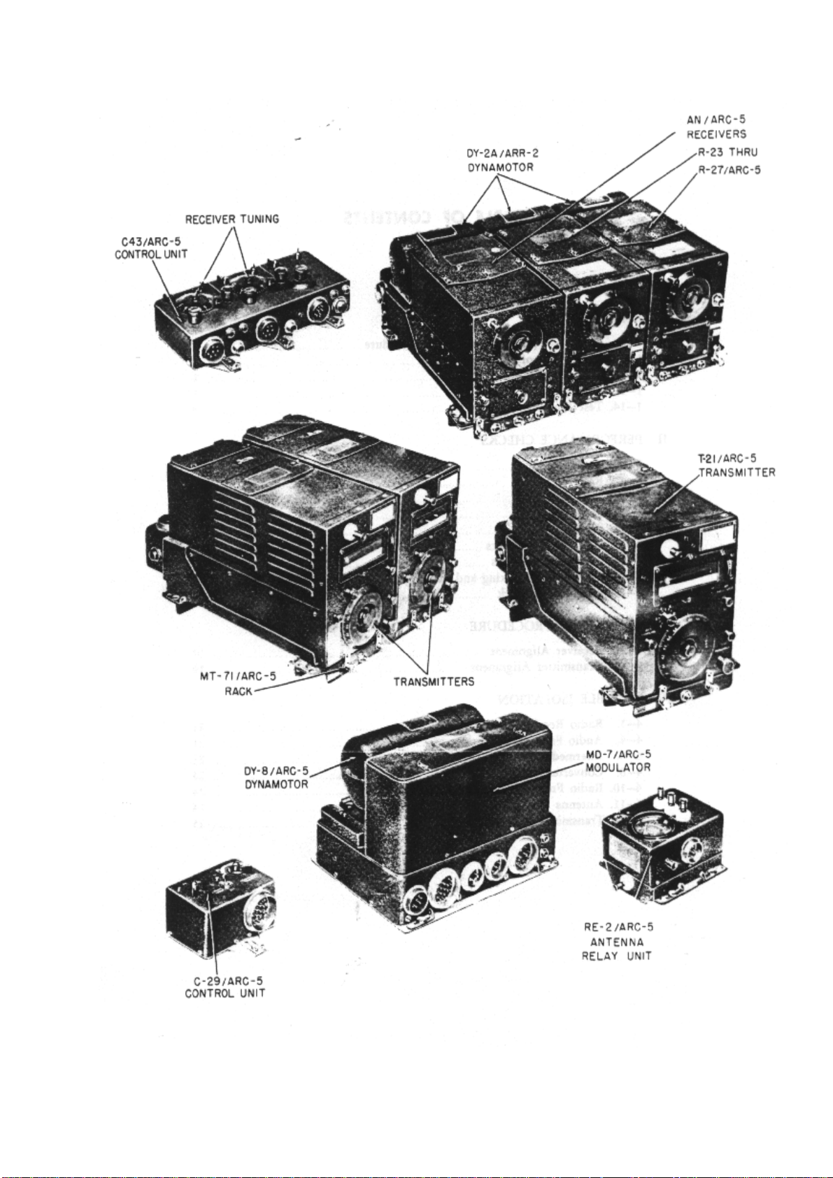
Figure 1-1. AN/ARC-5 Equipment
SECTION I INTRODUCTION
1--1. PURPOSE OF BENCH MAINTENANCE PROCEDURE.
1--2. The basic approach used in the development of this manual has been that of dividing all
equipments into two categories:
a. Components operating at or above a minimum standard of satisfactory performance.
b. Defective or poorly performing components.
1--3. Bench maintenance is reduced, first, to determining whether or not an equipment is operating
satisfactorily, and, second, repairing the equipment if it is found to be defective. This division results in
a procedure having four sections:
a. INTRODUCTION -- This section presents a brief description of the basic function of the subject
equipment, its primary power requirements, inter-unit connecting cables, a suggested bench mock-up,
and other information necessary for quick reference with respect to proper maintenance techniques.
b. PERFORMANCE CHECKS -- These are of primary importance and are to be performed in
sequence upon the subject equipment. An equipment that meets all the requirements of this series of
checks is thereby determined to be satisfactory. An equipment that fails in any one of several of the
check requirements is assigned, by means of proper references, to the appropriate steps in one or
both of the two sections described below.
c. ALIGNMENT -- This section details the steps necessary to return the equipment to a properly
aligned condition. Practical methods requiring a minimum of maintenance time are employed.
d. TROUBLE ISOLATION -- This section of the procedure is divided into sections, each of which deals
with a specific component, stage or stages according to the function of the equipment. When the
maintenance technician is referred to a section of TROUBLE ISOLATION by the failure of the
equipment to meet the standards set up in PERFORMANCE, he will find detailed instructions and data
pertinent to the function. Additional aids in the form of sectional schematics and suggested testing
techniques are at his fingertips. This eliminates time-consuming manual searching, thus increasing the
work output and efficiency of the technician.
1--4. DESCRIPTION OF PROCEDURE.
1--5. The procedure begins with a general description of the appearance, function, and operational
characteristics of the AN/ARC-5 Communications Equipment. It is followed by a block diagram, list of
test equipment and tools, and other necessary information. The procedure proper consists of
PERFORMANCE CHECKS, ALIGNMENT, and TROUBLE ISOLATION sections, each of these
making use of pictorial diagrams, photographs, and sectional schematics. These aids are related to
the written material by means of three types of symbols:
a. A star-encircled letter indicates a MAJOR CHECK POINT, at which satisfactory PERFORMANCE
can be most easily determined.
b. An encircled numeral indicates SECONDARY CHECK POINT, at which more detailed circuit
information such as voltage readings and waveforms, can be obtained for trouble analysis.
c. C-49 -- Manufacturer's circuit symbols, used to cross-reference all diagrams with the written
material.
1--6. USE OF THE PROCEDURE.
1--7. The proper procedure to follow in bench maintenance work is that given by the sequence of the
PERFORMANCE CHECKS. These checks follow an order which will most quickly reveal the proper or
improper performance of the equipment.
1--8. The failure of the equipment to meet one of these checks suggests the need for ALIGNMENT, or
TROUBLE ISOLATION, and appropriate references are made.
1--9. When the reason for defective operation is found and the defect has been corrected, the
technician is directed to return to the PERFORMANCE section, repeat the step at which defective
operation was first noted, and, if PERFORMANCE is satisfactory, to continue with the remainder of the
PERFORMANCE CHECKS.
1--10. Satisfactory completion of the last PERFORMANCE CHECK completes the bench maintenance
for the equipment.
Page 5

1--11. GENERAL DESCRIPTION OF AN/ARC-5 EQUIPMENT.
1--12. The model AN/ARC-5 Aircraft Radio Communication Equipment (See figure 1--1.) is a multichannel radio transmitter and receiver for use on aircraft having a 22 to 30-volt d-c power supply. The
receivers cover a frequency range of 190 kc to 9.1 mc in five independent units, each unit designed to
be mounted interchangeably into the receiver racks. Racks are available for either two, and/or threeunit installations, the receivers operating singly or simultaneously, depending upon requirements.
Provisions have been made for either local or remote control, but only remote controls are furnished
with the equipment. The receiver mounting racks will accommodate other rack types of equipment
such as the AN/ARR-2 Receiver and AN/ARC-5 VHF Transmitter-Receiver. These units will not be
covered in this procedure. The weight of the equipment, less cables and mechanical linkages, is 23.6
pounds for a two-receiver installation and 55.2 for a three-receiver installation.
1--13. The receivers are designed for the reception of CW, MCW or VOICE modulation. Manual gain
control is employed in conjunction with high level automatic gain control. The outputs of each receiver
may be paralleled on one line to a single headset, or divided for double headset reception by more
than one operator. A 600-ohm headset is to be used with this equipment. A single antenna is used for
all receivers and transmitters. The tuning dials are calibrated directly in mc and their accuracy is better
than 0.5 per cent. The transmitters cover the frequency range of 2.1 to 9.1 mc in five independent
units. They are designed to be installed in pairs. The transmitter frequency control dial is calibrated in
megacycles with an accuracy of .03 per cent or better. A crystal calibrator is used in conjunction with
an electron resonance indicator to spot-check the dial calibrations of each unit. The current drain from
the d-c power source is 8.8 amperes when transmitting with CW emission, and is reduced to 2.5
amperes on "stand-by". The carrier power output varies between eight watts with VOICE modulation to
Page 6
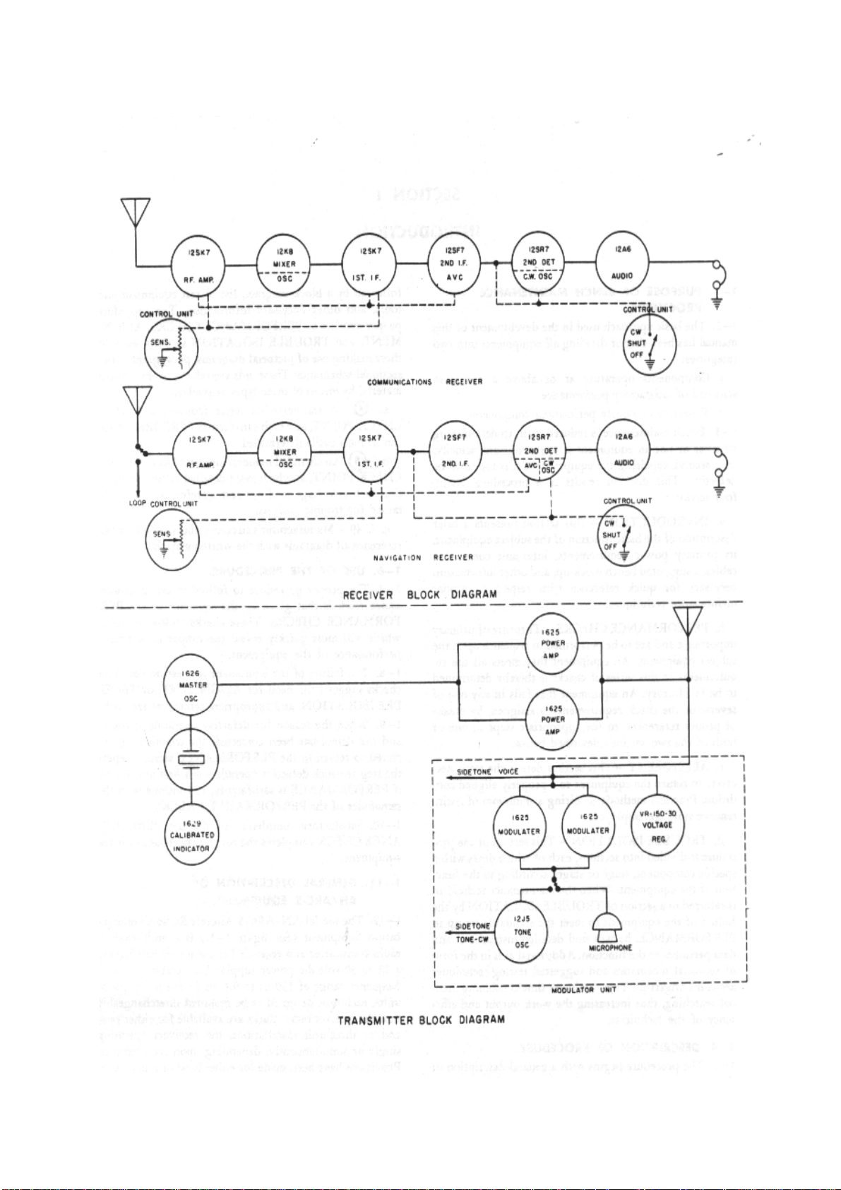
25 watts with CW emission.
Page 7

Figure 1-2. Receiver and Transmitter Block Diagrams
1--14. TEST EQUIPMENT.
DESCRIPTION RECOMMENDED
1. Bench Test Set AN/GRM-1 AN/ARC-5 TEST BENCH
2. Frequency Meter LM-13 LM Series
3. RF Signal
Generator
4. Audio Signal
Generator
5. Output Meter Weston 695 Daven OP-182
6. Voltmeter TS-352/U Simpson 260
7. VTVM TS-375/U RCP 662 or RCA Voltohmyst
8. Oscilloscope TS 239/UP Dumont 241
STANDARD
TS-413/U LP-5
TS-382A/U HP-200C
ALTERNATE
HARNESS Stock No. RI6-R1047-25
165
9. Tube Tester Hickok 547 Hickok 545 or 540
1--15. One additional extension cable will be required for the bench test setup to record modulation
wave forms in TROUBLE ISOLATION. It should be a two-conductor cable about six inches long
attached to terminals 10 and 17 of plug 6962 (the plug that fits into modulator receptacle (J-77). The
other end of the two wire extension cable is terminated in two insulated phone-tip jacks, properly
identified as terminals I0 and 17 respectively.
Note
If the AN/ARC-5/ARR-2A Test Bench Harness, ASO stock No. R16-R-1047-25, is
used in place of the AN/GRM-1, there will be an individual meter for each of the switch
positions of the I-104-A and the TS-58/GRM-1. The chart below shows the
corresponding meter for each of the switch positions on the I-104-A and the TS58/GRM-1.
Page 8
Page 9

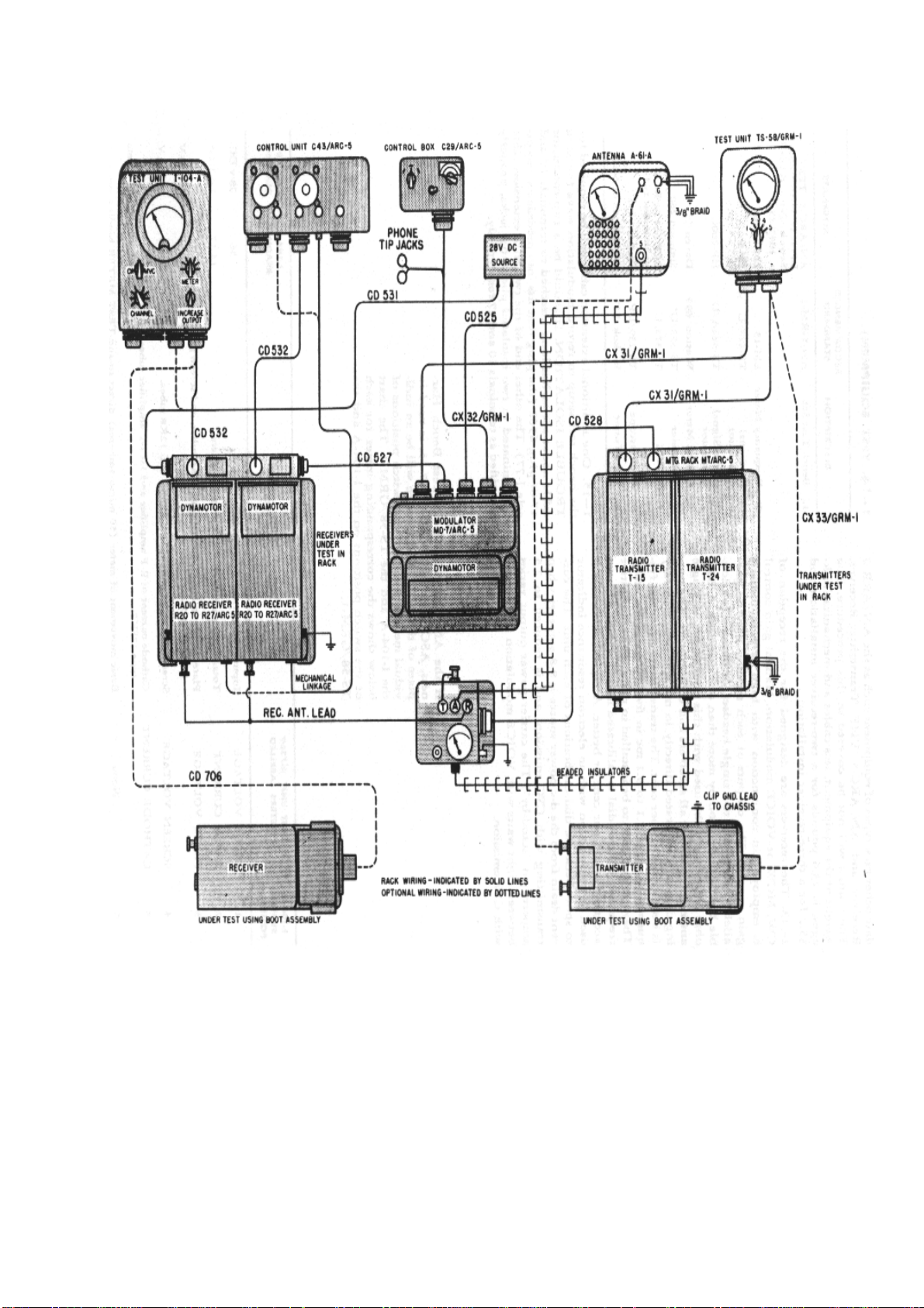
Figure 1-3. Test Equipment Diagram
I-104-A
SWITCH
POSITION
TEST
UNIT
#7369
CIRCUIT I-104-A
READING
#7369
READING
METERS
LABELLED
1 INPUT
VOLTAGE
2 INPUT
CURRENT
3 PLATE
VOLTAGE
Input voltage from primary
source.
Total input current from the
primary source.
Plate supply to 12SF7, 12SK7,
and 12K8 tubes, and screen grid
56 28 V DC
14-17 1.4-1.7 A
46-50 230-250 V
voltage on 12A6 tube.
4 SCREEN
VOLTAGE
5 CATHODE
CURRENT
Screen grid voltage to 12SF7,
12SK7 and 12K8 tubes.
Cathode current of R-F amplifier
and 1st I-F amplifier tubes, type
38-50 76-100 V
44-60 11-15 ma
12SK7s.
6 None Basic movement of meter (50 micro-amperes) direct to-and-
TEST METER binding posts on front panel of I-104-A. I-104A. Insert jumper wire between these two posts to protect the
meter movement.
TS-58/GRM-1
SWITCH
POSITION
TEST
UNIT
#9556
METERS
LABELLED
1 INPUT
VOLTAGE
2 SCREEN
VOLTAGE
3 PLATE
VOLTAGE
4 OSC.
PLATE
CURRENT
5 AMP.
PLATE
CURRENT
CIRCUIT
Input voltage from
primary source
Screen grid voltage to
PA tubes
Plate voltage to final PA
tubes
Plate current of master
oscillator tube, type
1626
Plate current of final PA
tubes type 1625
TS-58/GRM1 READING
#9556
READING
TONE CW TONE CW
54 54 27 27
28-31 48-
60
51-56 51-
55
32-46 32-
46
140155
510550
240300
510550
16-23 16-
23
ma
27-40 60-
80
68100
150200
ma
Page 10

TEST SET COMPONENTS
TYPE QTY DESIGNATION
ARMY NAVY
1 Antenna A-61-A
1 ANT. Relay
Unit
1 Control Unit
1 " "
3 " " MC-237
1 Cord CD-525
2 " CD-527
1 " CD-528
BC-442-A RE-2/ARC-5 Antenna relay (LF, MF, HF
USE
C-29/ARC-5 Transmitter control (or C-
C-43/ARC-5 Receiver control
Phantom antenna (LF, MF, HF
radio transmitter)
radio transmitter)
30A/ARC-5)
Local tuning crank
DC Outlet to modulator
6-Conductor
5-Conductor
2 " CD-531
2 " CD-532
1 " CD-706
1 " CD-905
2 "
1 "
1 "
6 Diagram
1 Dynamotor DM-33-A DY-8/ARC-5 Dynamotor (transmitting)
1 Modulator
CX-31/GRM-1 12-Conductor
CX-32/GRM-1 18-Conductor
CX-33/GRM-1 Transmitter rack adapter (7-
MD-7/ARC-5 Modulator equipped with
DC Outlet to receiver rack (2Conductor)
8-conductor
Receiver Rack adapter (7Conductor)
Sidetone test
Conductor)
Instructions for test equipment
AN/GRM-1
tubes
1 Mounting Base FT-279-A MT-62/ARC-5 Mounting for MT-63/ARC-5 or
FT-277-A Receiver rack
Page 11

1 " FT-227-A MT-70/ARC-5 Mounting for MT-71/ARC-5
Radio transmitter rack
1 " FT-225-A MT-76/ARC-5 Mounting (modulator)
1 " FT-229-A MT-77/ARC-5 Mounting (antenna relay unit)
1 Mounting Plate FT-228-A MT-80/ARC-5 Mounting (transmitter control
C-29/ARC-5 or C-50A/ARC-5)
1 " FT-222-A MT-98/ARC-5 Mounting (Receiver control C-
43/ARC-5)
1 Mounting Rack FT-277-A MT-63/ARC-5 Rack for two radio receivers
1 "
1 Test Unit I-104-A
1 " TS-
1 Cord CD-307-A
1 Microphone
1 Headset HS-33
58/GRM-1
MT-71/ARC-5 Rack for two radio transmitters
RS-38A Microphone
Test unit for radio receivers
Test unit for radio transmitters
Headset extension cord
600-ohm headset (two ANB-
H-1 receivers or equivalent)
Page 12
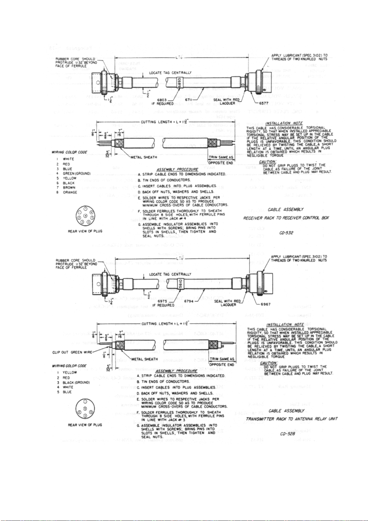
Figure 1-4. Cable Assemblies CD 532 and CD 528
Page 13
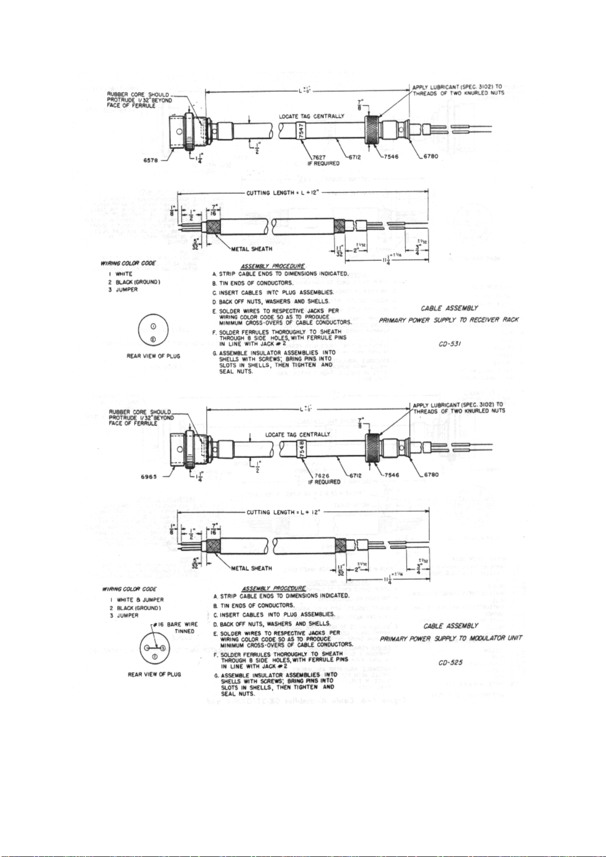
Figure 1-5. Cable Assemblies CD 531 and CD 525
Page 14
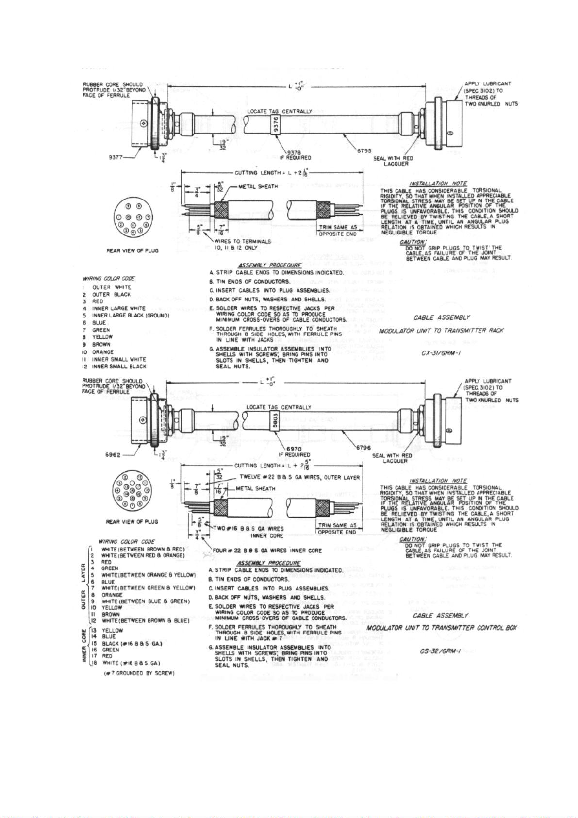
Figure 1-64. Cable Assemblies CX-31/GRM-1 and CS-32/GRM-1
Page 15
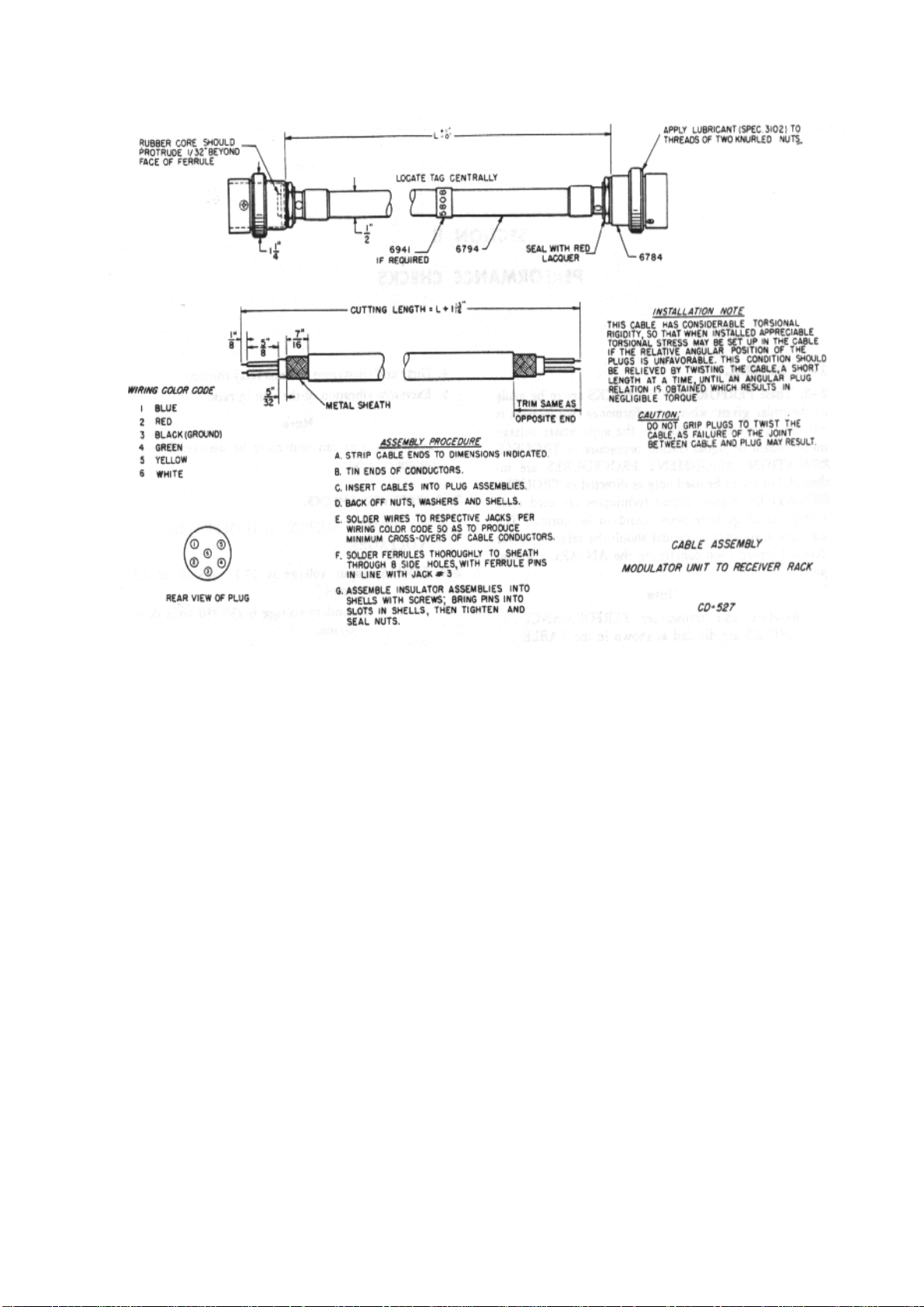
Figure 1-74. Cable Assembly CD 527
Page 16

NOTES
1. If Antenna relay unit RE-2/ARC-5, being tested, does not have a series capacitor, connect the
transmitter to "TRANS". Connect "ANT" of the antenna relay unit to terminal "A", instead of to terminal
"5", of antenna A-61-A.
2. Test Unit I-104-A normally is used with adapter cord CD-706 as shown. It may be used by attaching
cord CD-532 to either position of the receiver rack and when so employed, the meter will not indicate
when the meter switch is in position four or five. Volume control on AVC directly affects sidetone level.
3. The drawing shows the mechanical linkage (Part No. 6151) so that the mechanical tuning features
of the control units C-26 and C-43/ARC-5 and radio receivers R-20 to R-27/ARC-5 may be tested. No
linkage is furnished with the test equipment. Control unit MC-257 (local tuning crank) is furnished for
testing these receivers.
4. Test unit I-104-A may be made to function as a control unit and provide the channel selection when
testing VHF radio receiver R-28/ARC-5, by connecting cord CD-527 between jack J-103 on the radio
receiver and jack J-600 on the test unit.
5. Dynamotors *DY-2/ARR-2 and *DY-2A/ARR-2 are furnished with the particular radio receivers as
shown. Both dynamotors are interchangeable with dynamotors DM-32-A or CBY-21531.
6. Transmitters and receivers may be tested either by direct connection to the test equipment, using
cords CX-33/GRM-1 and CD-706, or by mounting in a one or two unit rack and using cords CX31/GRM-1 and CD-532.
Page 17
SECTION II PERFORMANCE CHECKS
2--1. GENERAL.
2--2. These PERFORMANCE CHECKS are to be made in the order given; when a performance
requirement is not met, a reference is made to the appropriate voltage measurement or signal tracing
procedure in TROUBLE ISOLATION. ALIGNMENT PROCEDURES are included, but are to be used
only as directed in TROUBLE ISOLATION. Signal tracing techniques are used after voltage readings
have been found to be normal. The standard maintenance manual should be referred to for detailed
information concerning the AN/ARC-5 Equipment.
Note
Receiver and transmitter PERFORMANCE CHECKS are divided as shown in the
TABLE OF CONTENTS.
2--3. VISUAL CHECKS. Connect the unit to be checked on the Test Set AN/GRM-1 rack and inspect
the unit for the following:
l. Faulty plugs, threads and pins.
2. Improper fusing.
3. Note evidence of excessive dynamotor ripple at the headset while tuning through the frequency
band.
4. Dirty and chattering antenna relay contacts.
5. Excessive vibration of the unit in rack.
Note
Open filaments can sometimes be detected by noting cold tubes.
2--4. RECEIVER CHECKS.
2--5. D-C POWER SUPPLY AND OPERATING VOLTAGES.
2--6. LIMITS: Input voltage is 27.5 volts dc at 1.7 amps.
Secondary voltage is 230-250 volts dc at 60 ma.
2--7. PRELIMINARY INSTRUCTIONS: Use Test Set AN/GRM-1, as shown in figure 1-3.
Use "Optional Wiring" for greater ease in maintenance testing. Do not key the transmitter. Apply d-c
power and turn the CONTROL SWITCH of Test Set I-104-A to MCW position, allowing the equipment
time to warm up. Do not remove the cover plates until trouble isolation or alignment is indicated by
performance failure. Advance INCREASE OUTPUT control to full clockwise position.
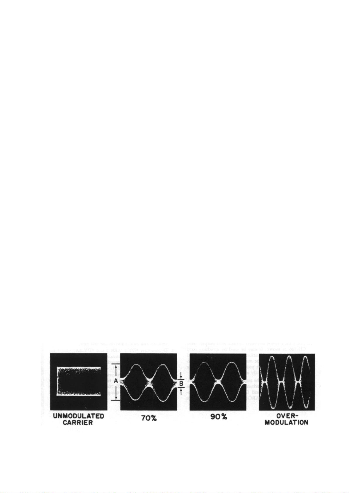
Figure 2-1. Modulation Envelopes
Page 18

2--8. TEST PROCEDURE.
STEP HEAD
TEST
SET
1 I-I04-A 1 Input voltage 27.5 v 56
2 I-I04-A 2 Input current 1.4-1.7 a 14-17
3 I-I04-A 3 Plate supply 230-250 v 46-50
4 I-I04-A 4 Screen
5 I-I04-A 5 Cathode
METER
SW
CIRCUIT
MEASURED
supply
current RF
and 1st IF
tubes
NORMAL
VALUES
76-100 v 38-50
11-15 ma 44-60
NORMAL
METER
INDIC.
2--9. BAND NOISE.
2--10. LIMITS: (Less than 15 milliwatts.)
2--11. TEST PROCEDURE.
ABNORMAL
METER INDIC.
Refer to
TROUBLE
ISOLATION
PROCEDURE,
Section IV,
Paragraph 4-1.
STEP TEST SET I-1O4-A NORMAL OUTPUT
INDICATION AND
CONNECTIONS
1 CONTROL SWITCH to CW or
MCW. INCREASE OUTPUT control
to maximum. Connect dummy
antenna (100 mmfd capacitor) from
Antenna post to ground. Use short
leads.
2 Peak receiver ALIGN INPUT
trimmer for maximum output at the
high frequency end of dial.
3 Turn the receiver frequency dial
from high to the low end and note
the maximum noise in the output
meter.
Output Meter, OP182, and
headphones
connected to
headset jack of 1104-A. Switch set to
600 ohms.
Reads less than 1.5
mw of noise.
Never exceed 1.5
mw.
POSSIBLE
CAUSES OF
ABNORMAL
IND.
Check dynamotor
brushes and
bearings.
Replace
dynamotor, if
necessary.
Same.
Page 19

2--12. SENSITIVITY.
2--13. LIMITS. Less than 10 uv R-F input to obtain 10 mw audio output with INCREASE OUTPUT
control set at maximum.
2--14. TEST PROCEDURE.
STEP RECEIVER
SETTINGS
1 FREQUENCY
at high end;
MCW
operation:
INCREASE
OUTPUT
control at
maximum.
2 Same as
Peak ALIGN
INPUT
trimmer.
Step 1.
SIG. GEN
CONNECTIONS
Through .006
mfd capacitor,
to receiver
Antenna post.
Set frequency to
agree with
receiver.
Use modulated
RF 30 per cent
at 400 or 1000
cycles.
Vary attenuator
to obtain 10 mw
receiver output.
OUTPUT INDIC.
&
CONNECTIONS
Output meter,
OP-182, and
headphones
connected to
headphone jack.
Set switch to
600 ohms.
Maximum
output.
Same as Step
1.
NORMAL
INDICATION
A peak on
output
meter.
10 uv input,
or less, to
obtain 10
mw audio
output.
POSSIBLE
CAUSES OF
ABNORMAL
IND.
Refer to
TROUBLE
ISOLATION,
Section IV,
paragraphs 4-4 to 4--11, and
ALIGNMENT
PROCEDURE,
Section 3--1.
3 Same as
Step 1.
except switch
to CW. Rock
receiver dial
carefully for
maximum
output.
4 Repeat Steps 1 through 3 with receiver dial set at low end.
Turn
MODULATION
switch to OFF.
Vary attenuator
to obtain 10 mw
receiver output.
Same as Step
1.
3.5 uv input
to obtain 10
mw output.
Check CW
oscillator and
ALIGNMENT
PROCEDURE,
Section III,
paragraph 3--
1.
Page 20

2--15. SELECTIVITY.
2--16. PRELIMINARY ADJUSTMENTS: Set the Model 695 output meter to the 1.5 volt range. Connect
a 300-ohm one-half or one watt composition resistor in parallel with the output meter; connect output
meter to receiver phone jack. Set the receiver INCREASE OUTPUT control to full counterclockwise
position. Tune the receiver and the signal generator to the proper frequency, as given in Table below.
Adjust the signal generator attenuators for 50 microvolts output, 30 per cent modulated at 400 cycles.
Advance the INCREASE OUTPUT control clockwise until the Model 695 output meter reads 1.0 volts.
The receiver dial and the ALIGN INPUT trimmer should be adjusted for maximum output meter
reading. Readjust the INCREASE OUTPUT control as necessary to give output meter reading of 1.0
volts. Receiver should be set for MCW operation.
STEP OUTPUT METER
SETTINGS
1 Switch output meter to 15
volt range.
2 Switch output meter to 6
volt range.
3 Switch output meter to 1.5
volt range.
4
5 Repeat Steps 1 through 4. Repeat Steps 1 through 4, detuning the
6 Compare values obtained in Steps 4 and 5; they should be very nearly equal in
value. Amount of frequency deviation recorded in Steps 4 and should not
exceed values given in Table below by more than 10 per cent.
SIGNAL GENERATOR SETTINGS
Adjust the output attenuators for 500 microvolts
output. (Switch MULTIPLIER to 100 position.)
Slowly detune FREQUENCY dial higher in
frequency until output meter reads less than 6.O
volts.
Slowly detune FREQUENCY dial higher in
frequency until output meter reads slightly less
than 1.5 volts.
Slowly and carefully detune FREQUENCY dial
higher in frequency until output meter reads 1.0
volts.
Record the amount of frequency deviation from
original setting at resonance, as given in
PRELIMINARY ADJUSTMENTS.
FREQUENCY dial lower in frequency.
7 Repeat Steps I through 5 on the R-23 (.19-.55 mcs.) receiver, with 50,000
microvolts input, instead of 500. Specifications given in Step 6 also apply.
RECEIVER FREQUENCY FREQUENCY DEVIATION EITHER SIDE OF
RESONANCE
R-23 .19-.55 mcs. .19 mcs. 3.0 kcs. 6.0 kcs.***
R-24 .52-1.5 mcs. .52 mcs. 5.0 kcs.
R-25 1.5-3.0 mcs. 1.5 mcs. 7.0 kcs.
R-26 3.0-6.0 mcs. 3.0 mcs. 15.0 kcs.
R-27 6.0-9.0 mcs. 6.0 mcs. 28.0 kcs.
Page 21

*** at 50,000 microvolts input
2--17. AVC CHARACTERISTICS.
2--18. LIMITS:
10X Normal sensitivity -- 50 to 150 mw.
100X Normal sensitivity -- 100 to 200 mw.
1000X Normal sensitivity -- 200 mw.
10000X Normal sensitivity -- 200 to 400 mw.
Note
Normal sensitivity is that setting of the signal generator output necessary to produce
10 mw receiver output.
2--19. PRELIMINARY INSTRUCTIONS. Obtain normal sensitivity before starting this check. This
check may be omitted on R-23 and R-24 navigation receivers.
2--20. TEST PROCEDURE.
STEP SIGNAL
GENERATOR
CONNECTIONS
1 Same as Steps 1
and 2 of
SENSITIVITY check.
2 Increase attenuator
setting 1000X the
setting at normal
sensitivity.
3 Increase attenuator
setting 10000X the
setting at normal
sensitivity.
OUTPUT INDIC.
&
CONNECTIONS
NORMAL
INDIC.
Record reading of
output meter.
Same as Step 1. 200 to 400
200 mw
indicates that
the audio level
is sufficient for
normal
operation.
mw
POSSIBLE
CAUSES OF
ABNORMAL
INDICATION
1. Audio
amplification is
insufficient.
Refer to
TROUBLE
ISOLATION,
Section IV,
paragraph 4--4.
2. Faulty AVC
indicated by a
decreasing
output with
increased signal
input.
Refer to
TROUBLE
ISOLATION,
Section IV,
paragraph 4--7.
4 Set attenuator to
100X the setting at
normal sensitivity.
5 Set attenuator to
10X the setting at
normal sensitivity.
Same as Step 1. 100 to 200
mw
Same as Step 1. 50 to 150 mw
Page 22

2--21. TRANSMITTER CHECKS.
2--22. POWER SUPPLY.
2--23. LIMITS: Input voltage 27.5 v dc.
Secondary voltage 545 v dc.
2--24. PRELIMINARY INSTRUCTIONS: Use Test Set, AN/GRM-1, as shown in figure 1--3. Apply d-c
power and allow time for the equipment to warm up. Depress the test key when recording all tests.
2--25. TEST PROCEDURE.
STEP C-29/ARC-5
CONTROL
BOX
1 Select
transmitter 1 or
2
corresponding
to the rack
position of unit.
Switch to CW
and key
transmitter.
2 Same. Switch TS-
3 Same. Switch TS-
OPERATION TS-
Dynamotor
runs. Note
any
evidence of
overload in
the form of
excessive
noise or
heat.
58 to
Position 1;
read heater
voltage.
58 to
Position 3;
read B+.
58/GRM-1
READS
54
divisions.
51-55
divisions.
VOLTMETER
VALUES
27.5 v
510-550 v
POSSIBLE
CAUSES
OF
ABNORMAL
IND.
Refer to
TROUBLE
ISOLATION,
Section IV,
paragraph
4--12.
4 Switch to
VOICE or
TONE. Key
transmitter.
Same. 51-55
divisions.
510-550 v
Page 23

2--26. TRANSMITTER TRACKING AND LOADING.
2--27. LIMIT: Phantom Antenna Plate Current:
No load (zero
coupling)
Loaded-MCW-VOICE 20-40 50-100 ma
Loaded-CW 60-80 150-200 ma
Frequency Calibration:
Within 0.03% of dial reading at any frequency, except at crystal frequency, where tolerance b 0.05%.
****
R-F Power Output:CW emission--2.25 amps minimum (25 watts)
VOICE emission--l.61 amps minimum (13 watts) unmod.
TONE emission--1.85 amps minimum (17 watts)
**** Above -- listed values of current measured on the ARC No. 7777 Phantom Antenna R-F current
meter.
TS-58/GRM-1, pos. 5
Current
10 25 ma
Page 24

2--28. TEST PROCEDURE.
STEP TRANSMITTER
CONTROLS
1 Select and
switch on
transmitter 1 or
2 depending on
position in rack.
Switch to CW.
Unlock all
transmitter
controls. Set
COUPLING
and ANT.
INDUCTANCE
at zero.
2 Set
FREQUENCY
dial, 100 kc
from high end.
3 Set COUPLING
at 3, and key
the transmitter.
OPERATION NORMAL
INDICATION
Set TS-58/GRMI switch to
position 5. Set
transmitter dial
to the lowest
frequency.
Observe TS-58
GRM-1 meter
while tuning
transmitter dial
throughout its
range.
TS-58/GRM-1
meter reading
should not exceed
10 through out the
range of the
tranmitter
FREQUENCY dial.
Vary ANT
INDUCTANCE
from 0 upward,
until antenna
current is
indicated. Adjust
COUPLING and
ANT
INDUCTANCE
carefully for
maximum
antenna current.
Antenna meter
reads 2.0 to 3.0
amps. TS58/GRM-1,
position 5, reads
60.80 (150-200
ma).
ABNORMAL
INDICATION
Refer to
TRANSMITTER
ALIGNMENT,
Section III,
paragraph 3t6.
Refer to TROUBLE
ISOLATION,
Section IV,
paragraph 4---16.
Refer to TROUBLE
ISOLATION,
Section IV,
paragraphs 4--15
and 4--16.
4 Switch to
VOICE. Key
transmitter,
5 Same. Key
transmitter,
6 Repeat Steps 3, 4, and 5 with transmitter dial set at 100 kc from low end of band.
7 Repeat Steps 3, 4, and 5 with transmitter dial set to the crystal frequency.
8 Repeat Steps 3, 4, and 5 with transmitter dial set to the operating trequency.
Reduce
COUPLING to
zero; then
advance
clockwise until
antenna meter
reads 1.6 amps.
Loosely couple
LM frequency
meter to
transmitter and
adjust it for zerobeat with
transmitter
frequency.
Antenna meter
reads 1.6 amps.
TS-58/GRM-1,
position 5, reads
20-40 (50-100
ma).
Frequency as
indicated by the
LM should be
within .03 per cent
of the frequency
indicated on
transmitter dial.
Refer to TROUBLE
ISOLATION,
Section IV,
paragraphs 4--16
and 4--17.
Refer to
TRANSMITTER
ALIGNMENT,
Section III,
paragraph 3----6.
Page 25

9 Lock all controls except coupling control.
2--29. MODULATION CHECK.
2--30. PRELIMINARY INSTRUCTIONS:
Modulation capabilities of the transmitter are determined by use of the oscilloscope, displaying a
modulation envelope type of pattern. In addition to the normal oscilloscope control settings, the
following should be observed:
Oscilloscope Settings--Vertical input to plates direct. Sync control to EXTERNAL.
Oscilloscope Connections-Sync voltage is obtained from one of the phone jacks in receiver rack or
junction box. The vertical input terminal of the oscilloscope is loosely coupled to the transmitter R-F
output, by attaching a wire, having good R-F insulation, to the vertical input terminal. The other end of
this wire is brought close to the phantom antenna lead from the transmitter. The degree of coupling
between these two leads will determine the vertical height of the modulation pattern.
STEP TRANSMITTER
CONTROLS
1 Set emission to
TONE. Key
transmitter.
Adjust
COUPLING
control for
maximum
Antenna
current.
2 Set emission to
VOICE. Key
transmitter.
MODULATION FORMULA: (A-B)/(A+B) * 100 = % modulation
OPERATION NORMAL
INDICATION
Adjust sweep
frequency
controls of
scope until two
or more audio
cycles are
displayed.
Adjust Sync
control for
steady pattern.
Speak in mike at
normal voice
level.
Sinewave
envelope pattern
with no
appreciable
distortion; see
figure 2--1.
Modulation
percentage should
be 60 per cent or
better as
calculated by use
of formula below.
Observe that the
modulation peaks
rise to a higher
value than that
obtained for
normal indication
in Step 1.
ABNORMAL
INDICATION
Refer to TROUBLE
ISOLATION,
Section IV,
paragraph 4--17.
Refer to TROUBLE
ISOLATION,
Section IV,
paragraph 4--17.
Page 26

SUMMARY TEST DATA CHECK OFF SHEET
AN/ARC-5
Antenna Relay__________Mike Jack___________Phone Jack___________Dynamotor Ripple
___________
Calibration (.08%)__________Vibration____________Align Input__________Dyn. Overhaul
Date_________
Max. Band Noise .19-.55mc .52-1.5mc 1.5-3.0mc 3.0-6.0mc 6.0-9.1mc
(15 mw) ________ ________ ________ ________ _________SENSITIVITY HIGH END LOW END
AVC CHARACTERISTICS
(7uv) CW MCW INPUT OUTPUT
RATIO LIMITS
.19-.55mc _________________ _________________ NOR. SENS. ________ uv. (mw)
.52-1.5mc _________________ _________________ 5X ________ 50-1001.5-3.0mc
_________________ _________________ 10X ________ 50-150
3.0-6.0mc _________________ _________________ 100X ________ 100-200
6.0-9.1mc _________________ _________________ 1000X ________ 100-300
10000X ________ 200-400 AUDIO OUTPUT CW ________ MCW ________ 200 200
SELECTIVITY
RECEIVER .19-.55mc .52-1.5mc 1.5-3.0mc 3.0-6.0mc 6.0-9.1mc LIMITS
2X ________ ________ ________ ________ _________ 2X -- 2.1-10 kc
10X ________ ________ ________ ________ _________ 10X -- 5-10 kc
10000X ________ ________ _________ ________ _________ 10000X -- 18 kc
TRANSMITTER POWER TRANSMITTER TRANSMITTER TRANSMITTER
OUTPUT FREQUENCY MODULATION TUNE-UP
CW __________
26 to 40 CW _________ VOICE _________ VOICE _________
.05% Approx. 70% Max. ant.
current
TONE __________
13 to 26
VOICE __________ CHANNEL SEL. POWER SUPPLY
13 to 26 1 ______ 2 ______ IN _______ OUT ______
27.5Vdc 545Vdc
Page 27
SECTION III ALIGNMENT PROCEDURE
3--1. RECEIVER ALIGNMENT.
Figure 3-1. Receiver Alignment Connections
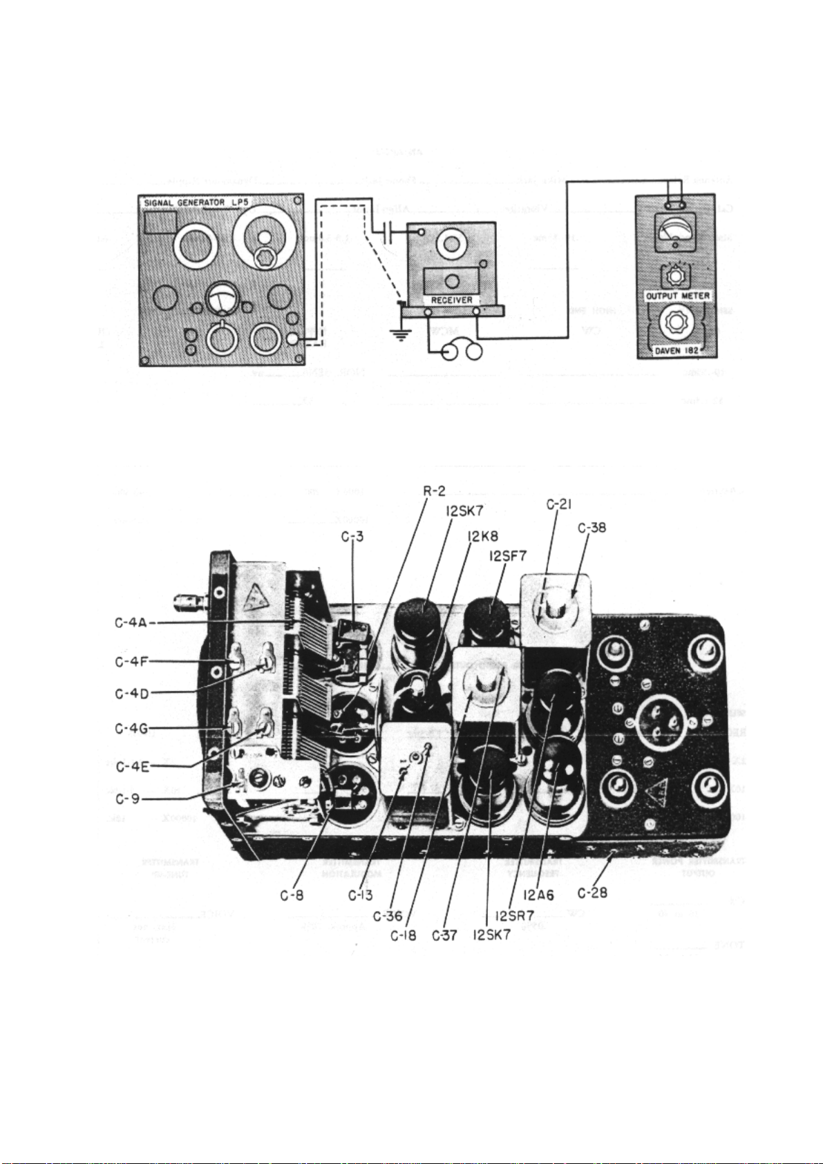
Figure 3-2. Location of Trimmers, Typical Receiver
Page 28

3--2. PRELIMINARY INSTRUCTIONS.Output Meter--Daven, Model OP-182, connected into headset jack on
receiver rack; IMPEDANCE SELECTOR set at 300 ohms.
Signal Generator--LP-5 or Hickok 19X connected between the point indicated on alignment chart and ground.
Controls-Set gain control at maximum, emission to MCW, signal generator switch ON, and dial as indicated in
chart.
Output Level--During alignment, the signal generator output must be attenuated to maintain the receiver output
at 10 mw as indicated by output meter.3--3. RECEIVER ALIGNMENT NOTES.3--4. The receivers R-23, R-24
and R-23A normally operate with over-coupled I.F stages. For alignment, each I-F stage must be loosely coupled
by pulling out the bakelite rod to the snap-out position. After the entire alignment is completed, the I-F stage
must be returned to the same over-coupled condition. For the R-23 and R-24, over-couple the first I-F stage; for
the R-23A and R-148, over-couple all I-F stages.
3--5. RECEIVER ALIGNMENT PROCEDURE. (See figures 3--1 and 3--2.) Before beginning alignment, check
the positions of C4F and C4G and adjust them if necessary
to the position shown in the table which follows. The positions shown are as seen from the FRONT of the
receiver.
RECEIVER C4F C4G
R-23
R-24
R-25
R-26
R-27
Front of Receiver
SIGNAL GENERATOR RECEIVER STEP
CONNECTIONS
TO RECEIVER
1 Through .006
mfd capacitor to
mixer grid use
MOD RF.
FREQUENCY
SETTINGS
85 kc
239 kc
705 kc
1415 kc
2830 kc
TYPE DIAL
SETTING
R-23
R-24
R-25
R-26
R-27
ANY
DIAL
SETTING
SPECIAL
INSTRUCTIONS
See Receiver
Alignment Note,
paragraph 3--3.
Adjust all I-F
trimmers as
indicated at
right, for
maximum output
meter reading.
TRIMMERS
C-21
C-38
C-37
C-18
C-36
C-13
2 Same Use
PURE RF.
Same
Switch receiver
to CW and
adjust BFO
trimmer for zerobeat.
C-28
Page 29

3 Same Use MOD
RF.
.52 mc
1.4 mc
2.9 mc
R-23
R-24
R-25
R-26
R-27
.52 mc
1.4 mc
2.9 mc
Switch to MCW.
Adjust oscillator
trimmer for
maximum output
meter reading.
C-4E
5.8 mc
8.9 mc
4 Through .006
mfd capacitor to
ANT post.
5 Same Same
6 Same
Same
.21 mc
.57 mc
1.55 mc
3.1 mc
R-23
R-24
R-25
R-26
R-27
5.8 mc
8.9 mc
Same Adjust R-F
trimmer and
ALIGN INPUT
trimmer for
maximum
output.
Same Adjust oscillator
trimmer for
maximum
output.
.21 mc
.57 mc
1.55 mc
3.1 mc
Adjust oscillator
padder, while
carefully rocking
the receiver dial,
for maximum
output.
C-4D
C-2
C-4E
C-9
6.1 mc
7 Repeat Steps 5 and 6 two or more times until there is no further increase in output when
Step 5 is performed. Then, proceed with Step 8.
8 Same Use
PURE RF.
9 Return I-F transformers to overcoupled condition: See Receiver Alignment Note,
paragraph 3--3.
Same as
Step 5
6.1 mc
Same as
Step 5
Switch to CW.
Adjust oscillator
trimmer for zerobeat.
C-4E
Page 30
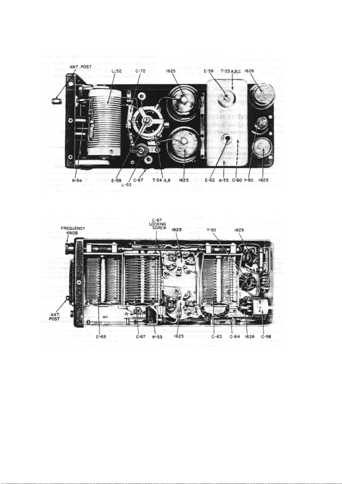
Figure 3-3. Transmitter Alignment Connections)
Figure 3-4. Transmitter Adjustment Points (Top)
Figure 3-5. Transmitter Adjustment Points (Bottom)
Page 31

3--6. TRANSMITTER ALIGNMENT.
3--7. PRELIMINARY INSTRUCTIONS.
Bench Setup- Connect transmitter, with outer shield removed, to AN/GRM-1, as shown in figure 1--3.
Frequency Meter -- LM-13 -- Couple as indicated in Transmitter Alignment Chart, (See figure 3--3.).
3-8. TRANSMITTER ALIGNMENT NOTES.
3--9. Zero-beat should occur at mid-position of E-62. If it is impossible to obtain a zero-beat with E-62,
C-60 may be unlocked from its normal locked position and adjusted to give a zero-beat with E-62 at
mid-position.
3-10. To correct frequency error at the low end, transmitter FREQUENCY by over-shooting the correct
setting an amount one-half that of the error. Adjust E-58 for zero-beat. Reset FREQUENCY to correct
setting and retrim C-60 for zero-beat. The reason for the latter operation is to achieve accuracy at the
high and low frequency points with a minimum number of steps.
3-11. To correct the tracking error, E-59 should be adjusted at the low frequency and by over-shooting
by one-half the number of turns necessary to obtain minimum plate current.TRANSMITTER
ALIGNMENT CHART (See figures 3--4 and 3--5.)
STEP CONNECTIONS
ON TS-58/GRM1
1 Connect
Phantom
Antenna to
transmitter
antenna post.
2
3 Frequency meter
loosely coupled
to dummy load
and set to same
frequency.
DIAL SETTING TRANSMITTER
OPERATION
T-18 2.9 mc
T-19 3.9 mc
T-20 5.2 mc
T-21 6.9 mc
T-22 9.0 mc
Same as Step 2. Adjust master
Turn transmitter ON.
Key transmitter.
Check
FREQUENCY
against crystal
frequency by tuning
for greatest shadow
on resonance
indicator.
Turn FREQUENCY
dial to setting
indicated; Emission
switch to VOICE.
Key transmitter.
Load transmitter by
adjusting for
maximum antenna
current.
oscillator trimmer for
zero-beat in
frequency meter
headphones. (See
Transmitter
Alignment Notes,
paragraph 3--9.)
ADJUST
FREQUENCY
knob
ANT IND.
ANT COUP.
E-62
4 Same as Step 3.
T-18 2.2 mc
Turn FREQUENCY
dial to setting
indicated. Vary
E-58
Page 32

T-19 3.1 mc
T-20 4.1 mc
T-21 5.4 mc
T-22 7.1 mc
5 Repeat Steps 3 and 4 until the final setting of E-62 with to cover in place is at a mid-
position and dial setting at the high and low is accurate. Dial setting should be within
0.03 per cent of actual frequency as indicated by LM frequency meter.
FREQUENCY dial
for zero-beat and
note error. To
correct, adjust
master oscillator
inductance. (See
Transmitter
Alignment Notes,
paragraph 3--10.)
6 Remove Phantom Antenna
to align R-F amplifier.
Remove frequency meter
and coupling. TS-58/GRM-I
switch to position 5.
7
Same as Step
2.
Same as Step
4.
Adjust for
minimum R-F
amplifier plate
current, which
should be
below 10
divisions (25
ma) on TS58/GRM-1
meter.
Turn
FREQUENCY
dial to setting
indicated to
check
tracking; note
if the minimum
R-F plate
current is
within 10 ma
of the
minimum
obtained in
Step 6. To
correct, adjust
iron core. (See
Transmitter
Alignment
Notes,
paragraph 3-1 l.)
C-67 (normally
locked)
8 Repeat Steps 6 and 7 until R-F amplifier is operating at minimum plate current at the
high frequency end and until tracking error is corrected.
9 Reconnect Phantom
Antenna to transmitter
antenna post.
Adjust
transmitter for
maximum
antenna
current output.
Lock all dial
controls at
completion of
this check.
ANT IND.
ANT COUP.
Page 33

SECTION IV TROUBLE ISOLATION
Figure 4-1. Typical Communications Receiver, Bottom View
Figure 4-2. Typical Receiver, Top View Inside, and Bottom View Dynamotor
Page 34

4--1. RADIO RECEIVER.
4--2. DYNAMOTOR UNIT.4--3. PRELIMINARY INSTRUCTIONS: All tests on the receiver will be
performed using the AN/GRM-1 Test Setup, as shown in figure 1--3.
STEP TEST
POINT
1. A Control switch to
2. B Control switch to
TEST
EQUIPMENT
CONTROLS
MCW or CW
position. Meter
switch to position
3.
MCW or CW
position. Meter
switch to position 1
and 2.
NORMAL INDICATION POSSIBLE
CAUSES OF
ABNORMAL
INDICATION
Dynamotor scans; I104-A meter indicates
from 46 to 50 (230 to
250 volts dc):
Position 1; meter reads
56 (28 volts dc).
Position 2; meter reads
14 to 17 (1.4-1.7 amps).
Shorted or open
dynamotor windings;
defective plugs or
jacks; open choke L14, L-15.
Blown fuses;
defective plugs or
jacks; open wiring,
shorted or open
dynamotor windings.
4--4. AUDIO-FREQUENCY CIRCUIT.
(See chart below.)
4--5. PRELIMINARY INSTRUCTIONS: Set Audio Signal Generator to 1000 cycles, zero output.
Connect TS-375/U or TS-352/U a-c test leads across Audio Signal Generator output terminals.
Connect the other pair of test leads from Audio Signal Generator output terminals to indicated test
points and chassis.
STEP
1 C Set voltmeter on 3 (or 2.5) volt
2 D Same as Step 1. Same as
TEST
POINT
TEST EQUIPMENT
CONTROLS
a-c range. Advance the output
level control on Audio Signal
Generator for 2.25 volt reading
on voltmeter.
ARC-5
RECEIVER
CONTROLS
Control
switch to
MCW
position.
Step 1.
NORMAL
INDICATION
Output
meter
reading of
200
miIliwatts or
greater.
Same as
Step 1.
POSSIBLE
CAUSES OF
ABNORMAL
INDICATION
If normal,
proceed to
paragraph 4-
-6. If not,
proceed with
Step 2,
paragraph 4-
-5.
Faulty power
amplifier
tube and/or
circuit
components,
Repair and
return to
Step 1,
paragraph 4-
-5 before
going to
paragraph 4-
Page 35

-6.
Figure 4-3. Dynamotor Test Points
Page 36
Page 37

Figure 4-4. Audio Frequency Test Points
4--6. INTERMEDIATE-FREQUENCY CIRCUIT.
(Follow chart below.)4--7. PRELIMINARY INSTRUCTIONS: Insert a 0.006 ufd capacitor in series with
the "hot" lead from the Signal Generator to the receiver. Use a signal modulated 30 per cent at 400 or
1000 cycles. Connect Signal Generator to indicated TEST POINT.
STEP
1 D Tune the Signal Generator to
TEST
POINT
TEST EQUIPMENT
CONTROLS
the following appropriate
frequency. (Rock the Signal
Generator FREQUENCY dial
for maximum output meter
reading.)
UNIT FREQUENCY
.19-.55 mc 85 kc 310 uv
.52-1.5 mc 239 kc 360 uv
ARC-5
RECEIVER
CONTROLS
Set the
CONTROL
switch on
the I-104-A
Test Unit to
MCW
position.
NORMAL
INDICATION
Output of 10
milliwatts or
greater
across the
300-ohm
load, for
Signal
Generator
input as
follows:
POSSIBLE
CAUSES OF
ABNORMAL
INDICATION
If normal,
proceed to
Step
1,paragraph
4--8. If not,
proceed to
Step 2,
paragraph 4-
-7.
2 1 Same as in Step 1. Same as in
1.5-3.0 mc 705 kc 910 uv
3.0-6.0 mc 1415 kc 330 uv
6.0-9.1 mc 2830 kc
Step 1.
430 uv
Same output
as in Step 1.
Signal
Generator
input as
follows:
8100 uv
7500 uv
10,000 uv
2400 uv
2500 uv
If normal,
trouble it in
converter
stage. If not
normal
proceed to
Step 3,
paragraph 4-
-7.
Page 38

3 2 Same as in Step 1. Same as in
Step 1.
Note
When a stage is found defective, test the tube in a tube checker and replace with
good tube if necessary. Conduct routine resistance and voltage measurements to
locate the defective or faulty component or components within a stage. When trouble
has been located and corrected, return to Step 1, paragraph 4--7 to determine that I-F
stages are operating satisfactorily.
Same output
as in Step 1.
Signal
Generator
input as
follows:
210,000 uv
220,000 uv
130,000 uv
99,000 uv
85,000 uv
If normal,
trouble is in
1st I-F
stage. If not
normal,
trouble is
probably in
2nd I-F
stage.
Page 39

4--8. CONVERTER CIRCUIT.(Follow chart below).
4--9. PRELIMINARY INSTRUCTIONS: Use a signal 50 per cent modulated at 400 or 1000 cycles.
Connect R-F Signal Generator between the TEST POINT and chassis. When using the VTVM, the d-c
probe having several megohms of series isolating resistance inserted at its tip should be used. (See
figures 4--7 and 4--8.)
STEP
1 1 Tune the Signal Generator to
TEST
POINT
TEST EQUIPMENT
CONTROLS
the following appropriate
frequency. (Rock the Signal
Generator FREQUENCY dial
for maximum output.)
UNIT FREQUENCY FREQUENCY NORMAL
ARC-5
RECEIVER
CONTROLS
Set the
CONTROL
switch on the
I-104-A Test
Unit to MCW
position.
NORMAL
INDICATION
Output of 10
milliwatts or
greater
across the
300-ohm
load, for
Signal
Generator
input as
follows:
SENS.
POSSIBLE
CAUSES OF
ABNORMAL
INDICATION
Defective
12K8 tube;
defective
circuit
components;
improper
alignment.
(Proceed to
step 2 to
check the
oscillator
circuit.) If
normal,
proceed to
step 1,
paragraph 4--10.
2 2 Set VTVM to 12-volt d-c
.19-.55 mc .55 mc .55 mc 370 uv
.52-1.5 mc 1.5 mc 1.5 mc 430 uv
1.5-3.0 mc 3.0 mc 3.0 mc 990 uv
3.0-6.0 mc 6.0 mc 6.0 mc 390 uv
6.0-9.1 mc 9.1 mc 9.1 mc 480 uv
range, negative polarity.
Connect d-c probe to TEST
POINT.
Vary the
frequency
from the high
end to the low
end of the
dial.
VTVM
indicates a 6 to -9 volts.
This voltage
varies over
the
frequency
range.
Weak or
defective
oscillator
section of
12K8
converter
tube.
Defective
components.
Improper
alignment.
Page 40

4--10. RADIO-FREQUENCY CIRCUIT.
( Follow chart below).
STEP
1 1 Same as Step 1, paragraph
TEST
POINT
TEST EQUIPMENT
CONTROLS
4--8.
UNIT FREQUENCY FREQUENCY NORMAL
.19-.55
mc
.52-1.5
mc
1.5-3.0
mc
3.0-6.0
mc
.55 mc .55 mc 50 uv
1.5 mc 1.5 mc 80 uv
3.0 mc 3.0 mc 150 uv
6.0 mc 6.0 mc 130 uv
ARC-5
RECEIVER
CONTROLS
Control to
MCW
NORMAL
INDICATION
Loud clear
tone.
SENS.
POSSIBLE
CAUSES OF
ABNORMAL
INDICATION
R-F tube or
circuit. If
normal
proceed to
Step 1,
paragraph 4-
-11.
6.0-9.1
mc
9.1 mc 9.1 mc 100 uv
4--11. ANTENNA CIRCUIT.
(Follow chart below).
STEP TEST
POINT
1. E Same as Step 1, paragraph
TEST EQUIPMENT
CONTROLS
4--8
UNIT FREQUENCY FREQUENCY NORMAL
.19-.55 mc .55 mc .55 mc 5 uv
.52-1.5 mc 1.5 mc 1.5 mc 7 uv
1.5-3.0 mc 3.0 mc 3.0 mc 7 uv
ARC-5
RECEIVER
CONTROLS
Control to
MCW
NORMAL
INDICATION
Loud clear
tone in
headset.
SENS.
POSSIBLE
CAUSES OF
ABNORMAL
INDICATION
Antenna
circuit. If
normal, this
completes
the receiver
check.
3.0-6.0 mc 6.0 mc 6.0 mc 6 uv
6.0-9.1 mc 9.1 mc 9.1 mc 6 uv
Page 41

Figure 4-5. Circuit Test Point Diagram
Page 42

4--12. TRANSMITTER AND MODULATOR.
4--13. DYNAMOTOR UNIT.
4--14. PRELIMINARY INSTRUCTIONS: All tests on the transmitter will be performed using the
AN/GRM-1 Test Setup optional wiring, illustrated in Figure 1--3, or the AN/ARC-5 Test Bench
Harness. Select transmitter one or two, corresponding to the desired unit's position in the test rack.
(See figure 4--15.)
STEP TEST
POINT
1. F Emission selector
2. G Switch on TS-58
TEST
EQUIPMENT
CONTROLS
switch to CW.
TRANS. POWER
switch to ON.
Switch on TS-58
set to position 1.
set to position 3.
Key the
transmitter.
NORMAL INDICATION POSSIBLE
CAUSES OF
ABNORMAL
INDICATION
Filaments light; relays
K-5O, K-53, and K-54
energized; dynamotor
runs. TS-58 meter
indicates 54 (27 volts).
TS-58 meter reads 5155 (510-550 volts d-c.)
Fuses F-50 and F-5I
blown; defective
coils on relays; dirty
or corroded
contacts; defective
dynamotor.
Defective relay K-52;
defective dynamotor
windings; shorted C55; shorted
components in 550volt circuit; defective
plugs and jacks on
equipment.
Page 43

Page 44
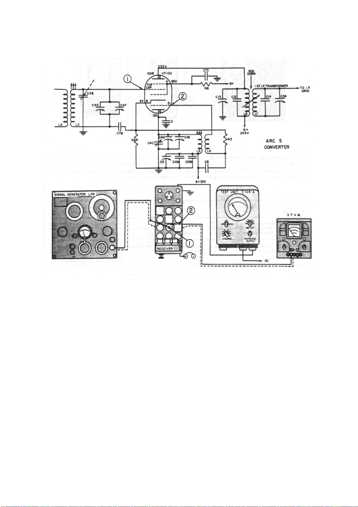
Figure 4-6. Circuit Test Points
Figure 4-7. Converter Circuit Test Points
Page 45

Page 46

Figure 4-8. Converter Circuit Test Points
Figure 4-9. Antenna Circuit Test Diagram
Figure 4-10. Antenna Circuit Test Points
Figure 4-11. Typical Transmitter, Top View, Shield Removed
Page 47

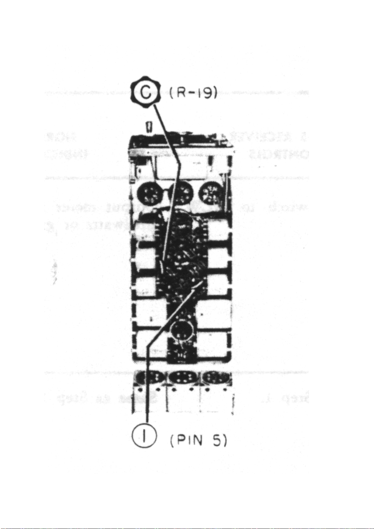
4--15. OSCILLATOR.
(Follow chart below.)
STEP
1.
2.
TEST
POINT
TEST
EQUIPMENT
CONTROLS
Emission selector
switch to CW. Set
VTVM on 120-volt
d-c scale, --polarity
and connect to
TEST
POINT H, the
ungrounded
terminal of PA grid
resistor, R-74 and
chassis. TRANS.
POWER switch to
ON. depress the
Microphone
button. See figure
4--17.
Set switch on TS58 to position 4.
Depress the
Microphone
button.
NORMAL
INDICATION
VTVM should indicate 40 to -70 volts d-c grid
bias, if oscillator is
supplying proper
excitation to PA grid
circuit.
TS-58 meter should
read 32-46 (16 to 23
ma. oscillator plate
current.)
POSSIBLE
CAUSES OF
ABNORMAL
INDICATION
Defective oscillator
tube or circuit
components
defective relay K-53;
defective PA tubes;
open R-74; low
voltage on oscillator.
Same as above;
oscillator not
oscillating; open R68, shorted C-58A.
3.
Tune transmitter
FREQUENCY
dial to calibrator
crystal frequency.
Depress the
Microphone
button.
Maximum shadow angle
on the "Magic
Eye" tube screen as the
FREQUENCY
dial is rotated to the
crystal frequency.
Same as above;
defective "Magic
Eye" tube; defective
crystal; no or low
voltages.
Page 48

Figure 4-12. Typical Transmitter, Bottom View
Figure 4-13. Modulator, Type MD-7/ARC-5, Bottom View
Page 49
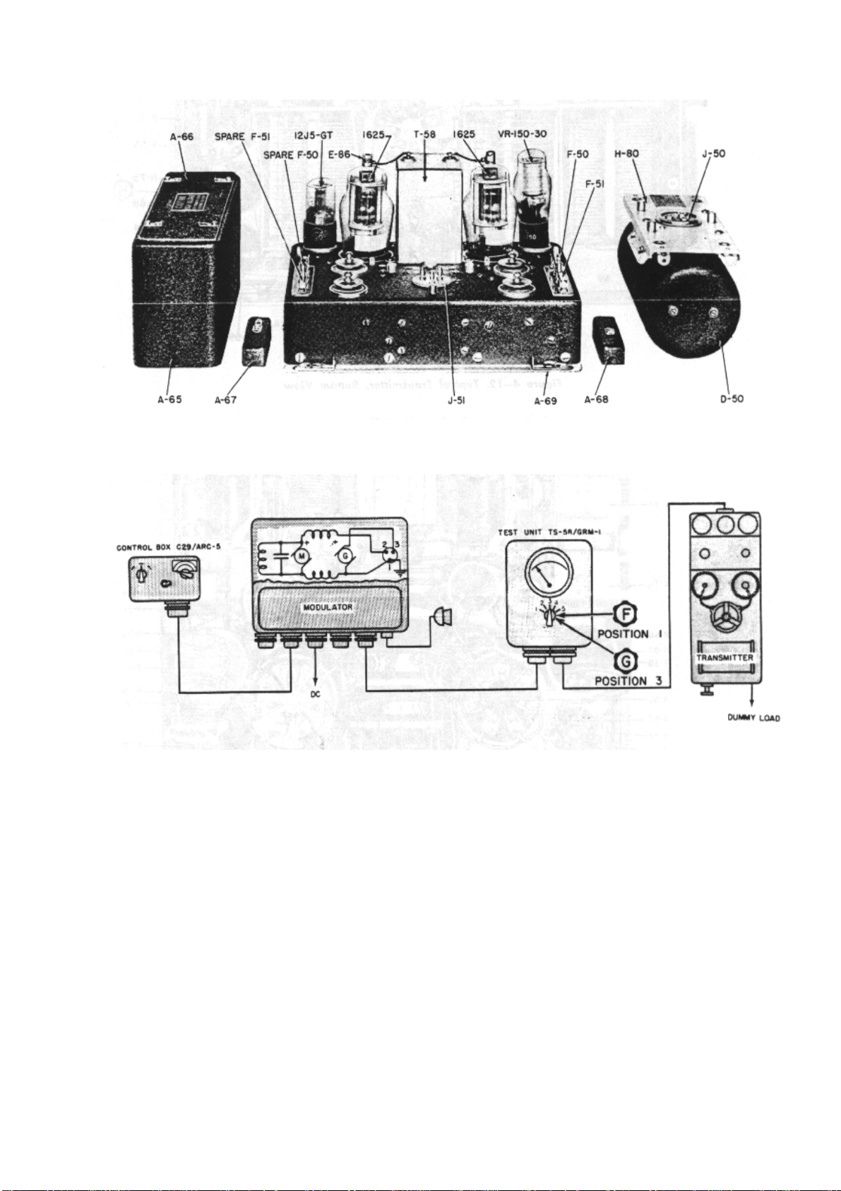
Figure 4-14. Typical MD-7/ARC-5 Modulator
Figure 4-15. Transmitter and Modulator Test Points
Page 50

Figure 4-16. Diagram
Page 51

Page 52

4--16. FINAL AMPLIFIER.
(Follow chart below.)
Figure 4-17. Oscillator Check Points
STEP TEST
POINT
1.
TEST
EQUIPMENT
CONTROLS
Emission switch to
CW. Power switch
to ON. Set
COUPLING
control to zero. Set
the TS-58 switch
to position 5.
Press the
Microphone
button. (See figure
4--19.)
NORMAL INDICATION POSSIBLE
CAUSES OF
ABNORMAL
INDICATION
TS-58 meter indicates
l0 (25 ma final PA plate
current.)
HIGH CURRENT:
Poor tracking, refer
to ALIGNMENT
section, paragraph
3--5; defective tubes
or other circuit
components in PA;
shorted capacitor
C-72.
NO CURRENT:
Defective relay K53; defective PA
tubes; no plate or
screen voltage on
PA tubes.
2.
3.
Same as Step 1,
except set TS-58
switch to position
2.
Same as Step I,
advance
COUPLING
control to 3. Adjust
ANT
TS-58 meter indicates
34-38 (170-190 volts PA
screen voltage.)
ANT current of over 2.0
amperes. TS-58
reading of 60 to 80 (150
HIGH VOLTAGE:
Defective PA tubes;
defective R-89.
LOW VOLTAGE:
Insufficient
excitation; refer to
TROUBLE
ISOLATION,
OSCILLATOR
section, paragraph
4--14; shorted
screen by-pass
capacitors C-64, C75, C-71; open
screen resistors R90, R-94, R-81 and
R-89; open
secondary windings
on modulation
transformer T-58.
Same as above: if
normal indications
are obtained in
Page 53

INDUCTANCE
control for
maximum PA plate
current and
maximum ANT
current.
to 200 ma final
PA plate current.)
Steps 1 and 2, but
not Step 3, relay K54 (K-55 also, if
used) may be
defective. Sliding
roller contact on
ANT TUNING coil
may be dirty,
corroded, and not
making good
electrical contact.
Page 54

4--17. MODULATOR.
(Follow chart below.)
4--18. PRELIMINARY INSTRUCTIONS: Set up equipment as illustrated in Figure
4--19, with the transmitter and associated equipment connected as in PERFORMANCE section. By
means of shielded cable, connect from vertical input terminals of scope to indicated TEST POINT.
Connect output meter across vertical input terminals of the scope. If Weston model 695 output meter
is used, set it to "0" decibel range. (If Daven model OP-182 is used set the power multiplier switch to
"1" position and set the impedance multiplier switch Phantom Antenna for maximum antenna current,
on CW emission, as described in the PERFORMANCE section, TRANSMITTER TRACKING AND
LOADING, paragraph 2-30, Steps 1, 2, and 3. Plug a pair of headphones into the headphone jack on
the receiver control box, or receiver rack. A loud audio tone or whistle should be heard during each
Step given below.
STEP TEST
POINT
1.
TEST
EQUIPMENT
CONTROLS
Emission switch to
VOICE. Ro-
tare COUPLING
control to zero,
key transmitter,
and advance
COUPLING
control clockwise
until Phantom
Antenna meter
reads 1.6
amperes. Set
emission
switch to TONE
and key
transmitter.
NORMAL INDICATION POSSIBLE CAUSES
OF ABNORMAL
INDICATION
Antenna current should
increase from
1.6 to 1.9 amperes,
when going from
VOICE to TONE
emission. Audio sine
wave pattern scope
output meter
should read +2
decibels. (1.5 mw on
OP-182.)
If no or low output
meter reading, tone
oscillator is defective.
If normal output
meter reading, but no
increase in an-
tenna current,
modulator tubes and
cir-
cuit components are
defective.
2.
Set emission
switch to VOICE.
Plug microphone
into MIC. jack,
J-73, on front of
modulator. Set
output meter on +
12 db range
(power multiplier
switch to 100
Antenna current should
increase from 1.6 to
1.9 amperes when
mike is Whistled into.
Output meter should
indicate + 14 db (+ 2
db, with 0 db now
being + 12 db) on loud
sustained whistle. (OP182 should read I000
mw). Approximate
audio sine wave
pattern on 'scope.
Defective modulator
tubes and circuit
components.
defective C-29/ARC5 control box.
Defective receptacles
on
modulator. Defective
microphone circuit.
Improper or no
voltages on
modulator tubes.
Defective modulation
transformer T-58.
Page 55

on OP-182). Press
microphone
button and whistle
loud, sustained
tone of constant
pitch into micro
phone.
Measure all voltages
and make continuity
measurements.
3.
Set emission
switch to TONE.
Key
transmitter.
Antenna current should
rise to 1.9 amperes.
Output meter should
read + 14 db (+ 2 db,
with 0 db being + 12
db).
(OP-182 meter should
read 700 milliwatts.)
Same as above.
Replace modulator
tubes with known
good ones. Check
for shorted
capacitors and open
resistors. Check
continuity from
modulator to
transmitter.
Figure 4-18. Final Amplifier Check Diagram
Page 56
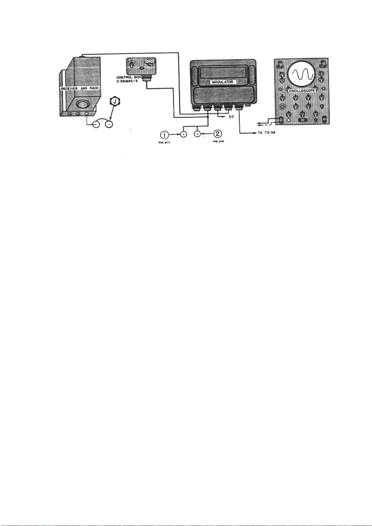
Figure 4-19. Modulator Check Diagram
 Loading...