

Aquacal SQ120R, SQ225, SQ125, SQ145, SQ166R Installation Manual
...
®
AquaCal
Installation Manual
Important
Read this document before operating / installing this product
For additional product manuals and operation / installation procedures, please visit www.AquaCal.com
LTP0098 REV 2

Table of Contents
Section 1 - Contacting AquaCal AutoPilot, Inc.
Section 2 - Safety
Section 3 - Installation
3.1 Dimensions 3
3.2 Positioning Equipment 5
3.3 Plumbing 5
3.3.a Clearances 5
3.3.b Water Flow Rates 6
3.3.c Adjusting Water Flow Using ΔT (Delta-T) 7
3.3.d Plumbing Requirements 9
3.3.e Plumbing Diagrams 9
3.3.f Water Connections to Heat Pump 12
3.3.g In-Line Chlorine Feeders 13
3.3.h Maintaining Ability to Winterize 13
3.3.i Adjusting Water Pressure Switch 14
3.4 Electrical 14
3.4.a Electrical Requirements 14
3.4.b Electrical Knockouts 16
3.4.c Access Panels 16
3.4.d Schematics 17
3.4.e Verifying Transformer Setting 17
3.4.f Three-Phase Adjustment 17
3.4.g Connecting Heat Pump to an External Controller 18
3.5 Service Level Programming 19
Section 4 - Operation
4.1 Energizing Heat Pump 23
4.2 Display Door 23
4.3 Display Lock 23
4.4 Display Panel 23
4.4.a Buttons 24
4.4.b Indicator Lights 24
4.4.c Display 24
i

4.5 User Level Factory Defaults 25
4.6 Setting Operating Mode 26
4.7 Selecting Celsius or Fahrenheit 26
4.8 Setting Thermostats 26
4.9 User Lock Option (Enable) 27
4.10 User Lock Option (Disable) 28
4.11 User Lock Option (Entering Pass Code) 28
4.12 Operating Heat Pump (With an External Controller) 29
Section 5 - Maintenance
5.1 Water Chemistry 30
5.2 Cleaning Equipment After Installation 30
5.3 Planned Maintenance 31
5.4 Winterizing 32
Section 6 - Troubleshooting
6.1 Fault Codes 34
6.2 Issues and Resolutions 36
Section 7 - Appendix
7.1 Identifying Model Specifications 39
7.2 Weights 40
7.3 Initial Heating Recommendations 40
7.4 Initial Cooling Recommendations 40
7.5 Available Accessories 40
ii
SECTION 1 - CONTACTING AQUACAL AUTOPILOT, INC.
For further assistance, please contact AquaCal AutoPilot, Inc. Technical Support. To better assist you,
please have the heat pump model and serial number available. See "Identifying Model Specifications" on
page 39.
Website www.AquaCal.com
Request Service Online www.AquaCal.com/request-heat-pump-service/
Phone (1) 727-823-5642
Hours 8-5 pm, Eastern M-F
SECTION 2 - SAFETY
l For personal safety, and to avoid damage to equipment, follow all safety instructions displayed on the equipment
and within this manual. Repair and service of heat pump must be performed by an authorized service center.
l Warranties may be voided if the equipment has been improperly installed, maintained or serviced.
l
If service is deemed necessary, please contact AquaCal®Technical Support. See "Contacting AquaCal
AutoPilot, Inc." on page 1.
SAFETY SIGNALS
Throughout this document, safety signals have been placed where particular attention is
required.
WARNING - signals relate to personal safety.
CAUTION - signals promote avoiding damage to the equipment.
When installing and using your heat pump basic safety precautions must always be followed, including the
following:
WARNING - Failure to heed the following may result in injury or death.
l Installation and repairs must be performed by a qualified technician.
l The heat pump contains refrigerant under pressure. Repairs to the refrigerant circuit must not be attempted by
untrained and / or unqualified individuals. Service must be performed only by qualified HVAC technicians.
Recover refrigerant before opening the system.
l The heat pump utilizes high voltage and rotating equipment. Use caution when servicing.
l Electrical installation and service should be performed by a Licensed Electrician only.
l Improper water chemistry can present a serious health hazard. To avoid possible hazards, maintain pool / spa
water per standards detailed in this document.
l Prolonged immersion in water warmer than normal body temperature may cause a condition known as
Hyperthermia. The symptoms of Hyperthermia include unawareness of impending hazard, failure to perceive
heat, failure to recognize the need to exit the spa, and unconsciousness. The use of alcohol, drugs, or medication
can greatly increase the risk of fatal Hyperthermia. In addition, persons having an adverse medical history, or
pregnant women, should consult a physician before using a hot tub or spa. Children and the extreme elderly
should be supervised by a responsible adult.
l Prolonged immersion in water colder than normal body temperature may cause a condition known as
Hypothermia. The symptoms of Hypothermia include shivering (although as hypothermia worsens, shivering
stops), clumsiness or lack of coordination, slurred speech or mumbling, confusion and poor decision-making,
drowsiness or low energy, lack of concern about personal welfare, progressive loss of consciousness, weak
pulse and slow or shallow breathing. In addition, persons having an adverse medical history, or pregnant
women, should consult a physician before immersing in a cold body of water. Children and the extreme elderly
should be supervised by a responsible adult.
Page - 1

CAUTION - Failure to heed the following may result in equipment damage.
l Maintain proper water chemistry in order to avoid damage to pump, filter, pool shell, etc.
l Water flow exceeding maximum flow rate requires a bypass. Damage due to excessive water flow will void
warranty.
SAVE THESE INSTRUCTIONS
Page - 2
SECTION 3 - INSTALLATION
WARNING - Failure to heed the following may result in injury or death.
l Installation of this equipment by anyone other than a qualified installer can result in a safety hazard. The
information contained throughout the "Installation" section is intended for use by qualified installation
technicians familiar with the swimming Pool / Spa safety standards.
CAUTION - Failure to heed the following may result in equipment damage.
l Failure to protect equipment against corrosive conditions will adversely affect the life of the equipment and will
void equipment warranty.
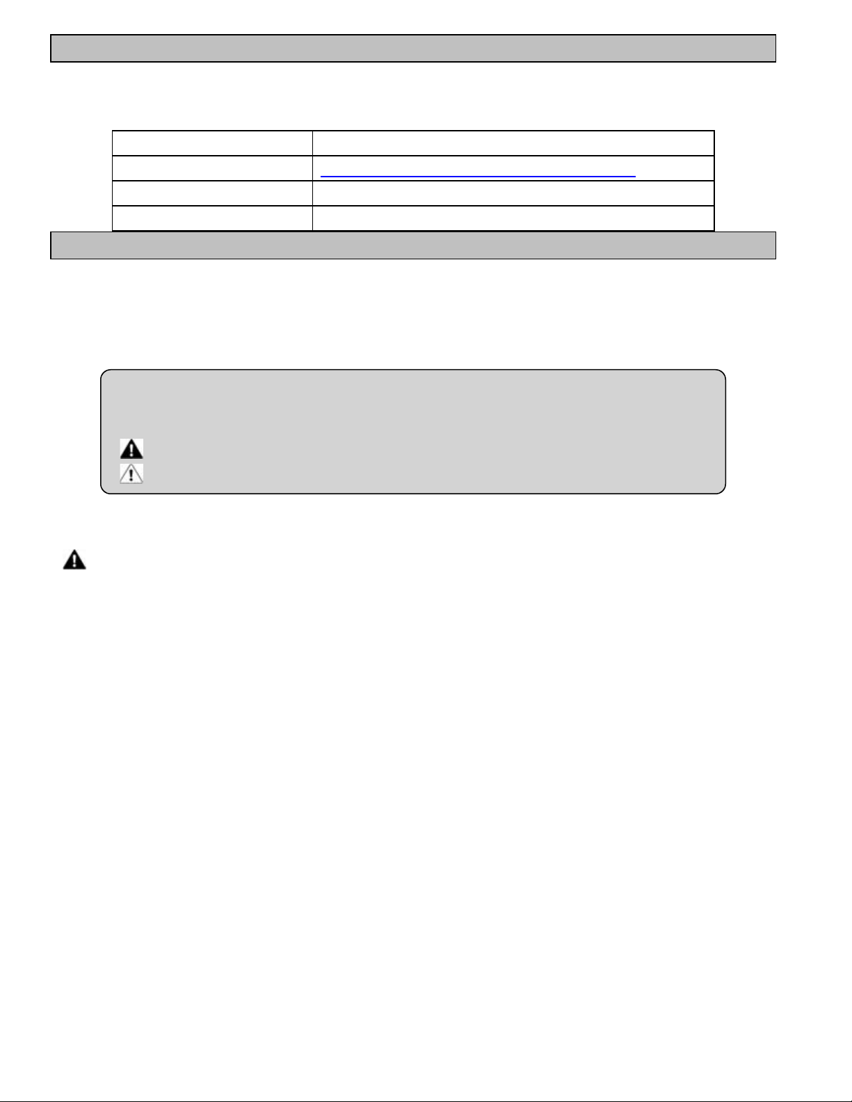
3.1 Dimensions
Dimensions (HeatWave SuperQuiet®SQ120R, SQ125, SQ145, SQ166R and SQ225)
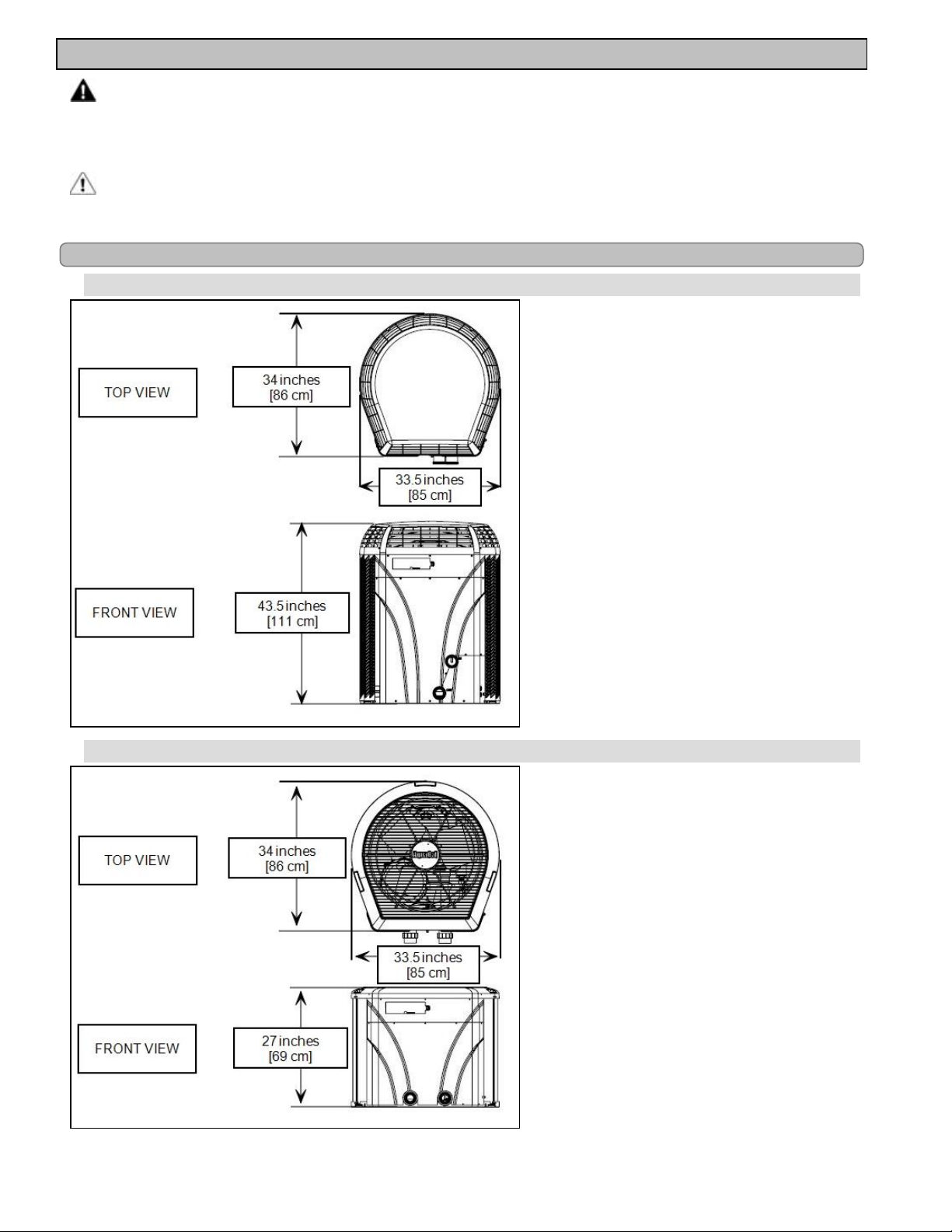
Dimensions (TropiCal®T035, T055 and T075)
Page - 3
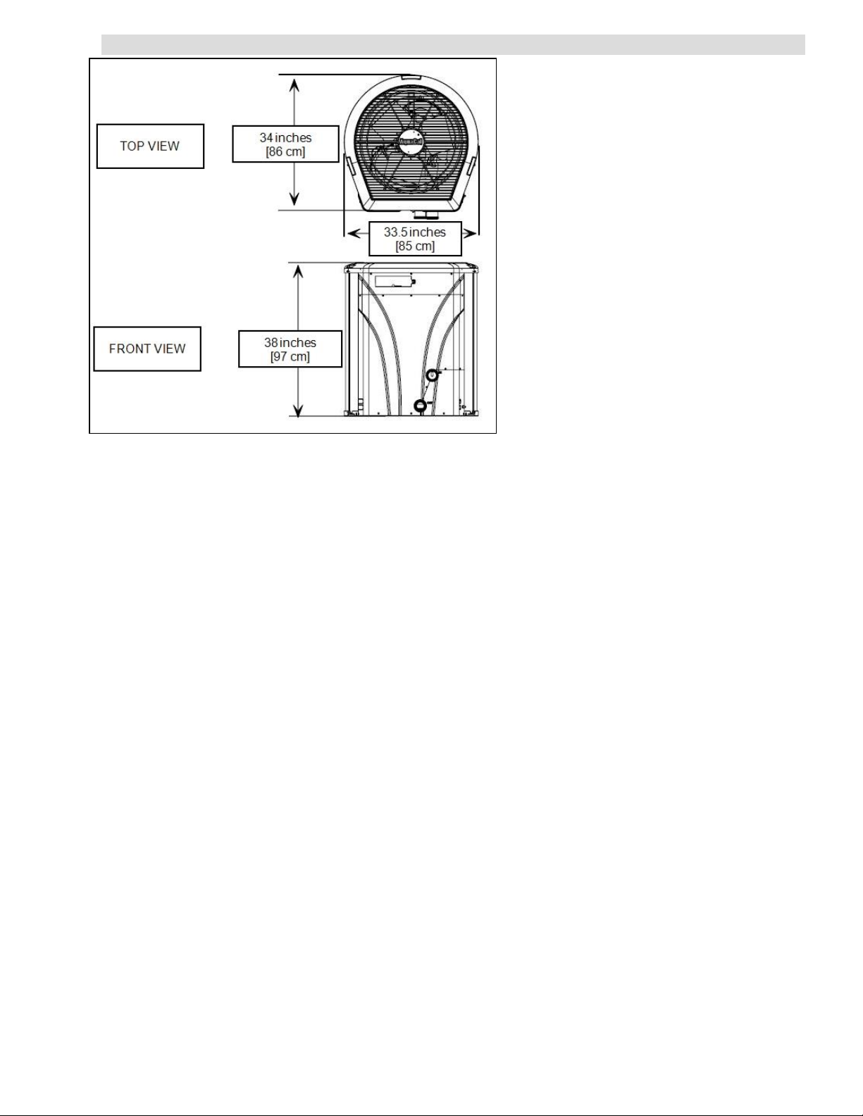
Dimensions (TropiCal®T090, T115 and T135)
Page - 4

3.2 Positioning Equipment
Controlling Irrigation and Rainwater Runoff
l Irrigation water may damage heat pump components. Have irrigation water directed away from the heat pump.
l The heat pump will withstand normal rainfall. Do not allow a roof slope to direct rainwater onto the heat pump.
Have a gutter installed on the roof edge to direct this water away from the heat pump. Or install the heat pump in
another location.
Planning for Condensation
The heat pump can produce a large amount of water in the form of condensation. The amount of water
depends on air temperature and humidity.
l Install the heat pump with enough height to allow for water drainage.
l Plan for water drainage disposal as needed.
Mounting Pad Requirements
l Build the heat pump pad out of concrete or another code-approved material.
l
Confirm the pad can support the weight of the heat pump. See "Weights" on page 40.
l Elevate the pad enough to allow for drainage.
l Make sure the pad is flat and level.
l Have the pad extend at least 6 inches from the heat pump base in all directions.
l Do not install the heat pump on soil or grass.
l Do not allow the heat pump base to touch the buildings foundation.
l Do not place the heat pump directly on a concrete floor inside a building. This can cause noisy equipment
vibration. Install vibration dampeners between the heat pump base and floor.
l Equipment pad must meet all requirements of authorities having code-related jurisdiction.
Anchoring to Pad
l Follow all applicable local, state, and national requirements regarding wind load anchoring.
l The shipping brackets used to tie the heat pump to the pallet are approved mounting (hurricane) brackets. They
can be used to anchor the heat pump to the pad.
l
If needed, contact AquaCal®Customer Support to obtain the correct anchoring kit information. Please have the
heat pump model number and serial number when requesting support. See "Identifying Model Specifications" on
page 39.
3.3 Plumbing
3.3.a Clearances
l Proper air circulation is required for the heat pump to operate efficiently. Avoid placing objects near or on top of
the heat pump. This includes shrubbery and lawn furniture. These objects will also hinder maintenance access.
l Avoid storing chemical containers near the heat pump. The chemicals can cause equipment damage.
Page - 5
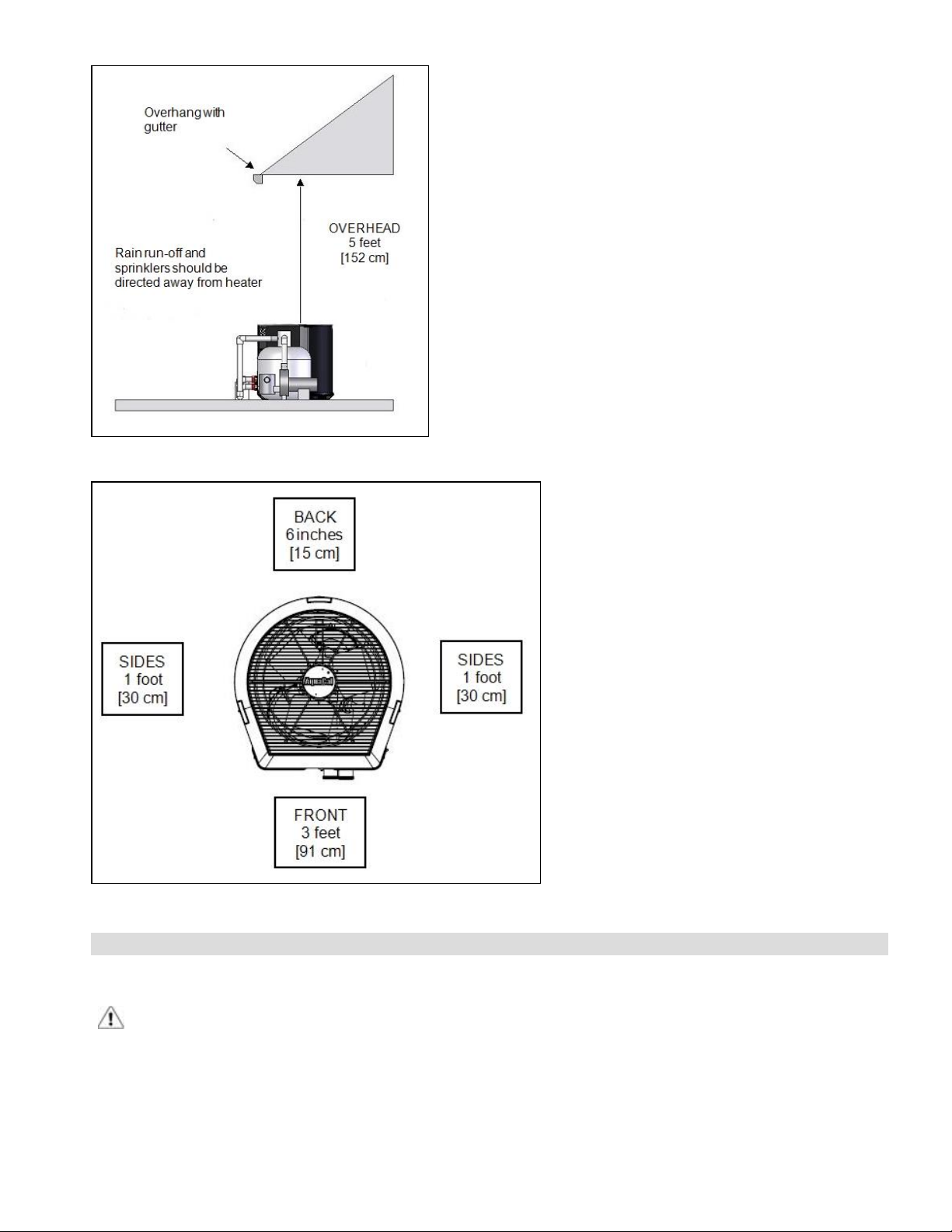
Overhead Clearance
HeatWave SuperQuiet®and TropiCal®(Top View)
3.3.b Water Flow Rates
Maintain water flow rates as indicated. Please note, these specifications relate to the heat pump only. Codespecified whole system turnover rates must be satisfied.
CAUTION - Failure to heed the following may result in equipment damage.
l Water flow exceeding maximum flow rate may damage heat exchanger; such damage will not be covered under
the equipment warranty
Page - 6

SQ120R
SQ125
SQ145
SQ166R
SQ225
MODEL HEAT EXCHANGER TYPE
Titanium ThermoLink
Titanium ThermoLink
Titanium ThermoLink
Titanium ThermoLink
Titanium ThermoLink
®
®
®
®
®
FLOW RATES
MINIMUM MAXIMUM
30 GPM 70 GPM
30 GPM 70 GPM
30 GPM 70 GPM
30 GPM 70 GPM
30 GPM 70 GPM
T035
T055
T075
T090
T115
T135
Titanium Tube-in-Tube 20 GPM 45 GPM
Titanium Tube-in-Tube 20 GPM 45 GPM
Titanium Tube-in-Tube 20 GPM 45 GPM
Titanium ThermoLink
Titanium ThermoLink
Titanium ThermoLink
®
®
®
30 GPM 70 GPM
30 GPM 70 GPM
30 GPM 70 GPM
If water flow through the heat pump is reduced, performance will suffer and internal safety devices may
deactivate the heat pump with error codes HP and HP5, or (if equipped) an LP and LP5.
l Operate water filtration devices per manufacturer's specifications. Dirty filters can cause reduced water flow to the
heat pump. An increase of 7-10 psi higher than the clean filter pressure typically reduces flow rates. This requires
the filter to be cleaned or back-washed
l Keep baskets free of debris. Similar to a dirty filter, large volumes of debris in the pump and skimmer baskets can
reduce water flow.
l Check for improper valve settings. A partially closed valve after the filter, or a full-open bypass around the heat
pump, will cause insufficient water flow through the heat pump.
l The maximum static (or operating pressure) is 50 pounds-per-square-inch (PSI). These specifications relate to the
heat pump only. Code-specified whole system turnover rates must be satisfied.
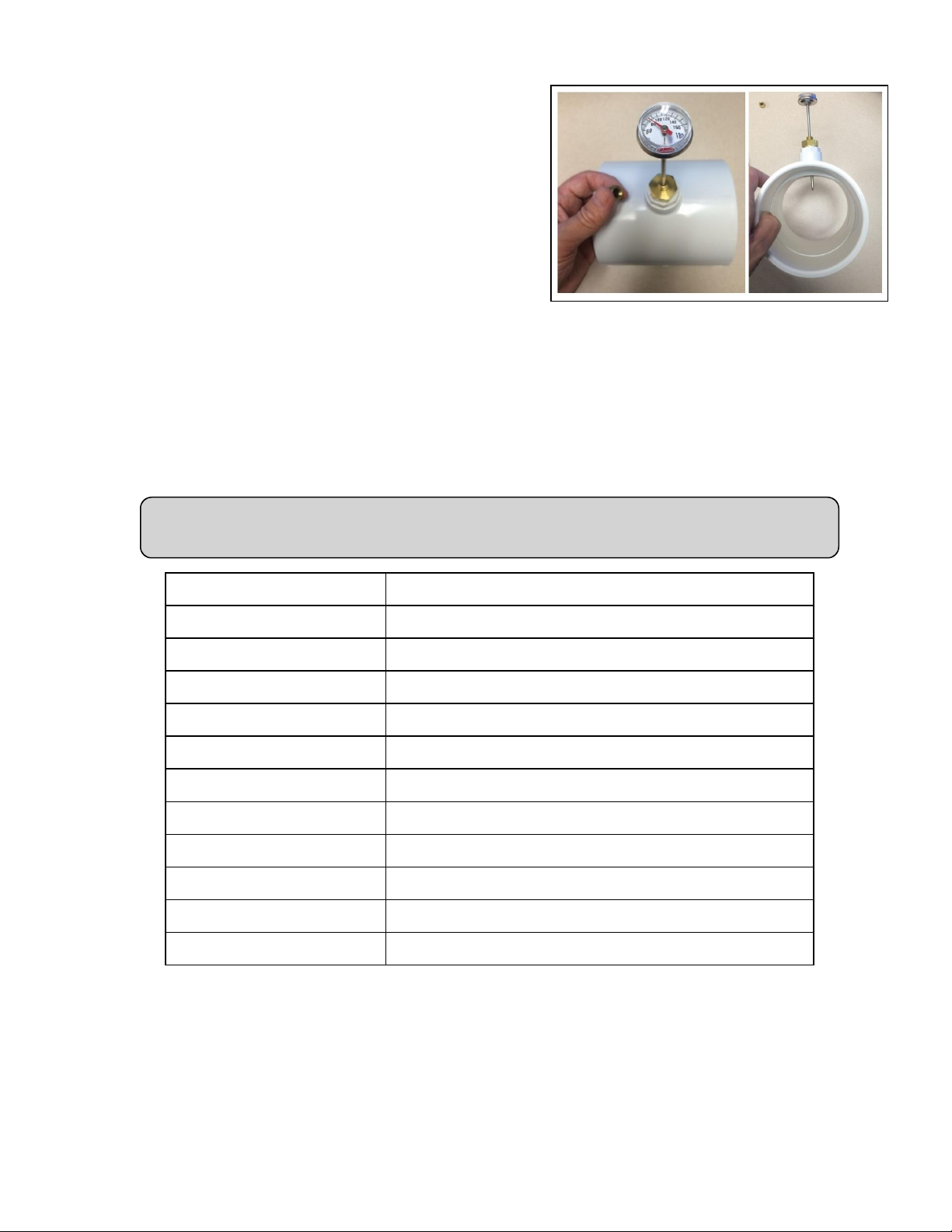
3.3.c Adjusting Water Flow Using ΔT (Delta-T)
The Delta-T is the temperature difference between the water temperatures entering and leaving the heat
pump. The equipment can be fine-tuned for maximum performance by balancing water flow rates to
maintain an ideal ∆T.
l Installed Temperature / Pressure probes and ports are required to perform the following procedures.
l
This adjustment procedure is to be completed with the unit in HEA mode only; ACH and COO discharge
temperatures are not shown.
PLEASE NOTE -
Temperature / Pressure ports are required for all commercial applications.
They are strongly recommended (but not required) for residential installations.
Page - 7
1.
Adjust heat pump thermostat to its lowest setting while in
HEA mode.
2.
Deactivate the water filtration pump.
3.
Adjust valves to a halfway open position leading to the
heat pump.
4.
Adjust valves to a fully open position leading away from
the heat pump.
5.
Activate the pool water filtration pump.
6.
Slowly turn the thermostat up until the heat pump
activates.
l After a four-minute delay, the heat pump
compressor will start.
7.
With the heat pump running, confirm water filtration
pump is operating properly with adequate flow and no
short cycling. If needed, clean filters leading to the heat pump.
8.
Wait for water and refrigerant pressure to stabilize (approximately 5 minutes).
9.
Adjust valves in the following order:
A.
Adjust valve leading away from the heat pump to correct temperatures measured with a temperature
pressure probe.
B.
Allow pressure to stabilize . Then check temperature again. Re-adjust valve leading away from the
heat pump as needed.
10.
Mark valves at these positions for future reference.
Temperature / Pressure Port
(Shown with Probe)
Temperature differences are based on pool temperatures of 72° (+ or – 3° F). For water
temperatures outside this range, contact AquaCal®Technical Support.
MODEL TEMPERATURE
SQ120R 3° to 7° F
SQ125 3° to 7° F
SQ145 3° to 7° F
SQ166R 3° to 8° F
SQ225 4° to 9° F
T035 1° to 4° F
T055 2° to 5° F
T075 3° to 7° F
T090 3° to 6° F
T115 3° to 7° F
T135 4° to 8° F
Table 1 - Temperature Chart
Page - 8
3.3.d Plumbing Requirements
CAUTION - Failure to heed the following may result in equipment damage.
l Do not use glue on the threaded portion of the equipment’s unions. A glued-in-place union will prevent the
equipment from being properly winterized.
l The heat pump must receive water flow within the specified minimum ranges under worst-case conditions such
as a fouled water filter.
l Water flow exceeding maximum flow rates may damage heat pump and will not be covered under equipment
warranty. See "Water Flow Rates" on page 6.
l Install a bypass valve whenever water-flow may exceed maximum rating.
l See "5 lb Bypass Valve Kit (Kit STK0135)" on page 40.
l
For additional guidance testing water flow rates, please contact AquaCal®Technical Support.
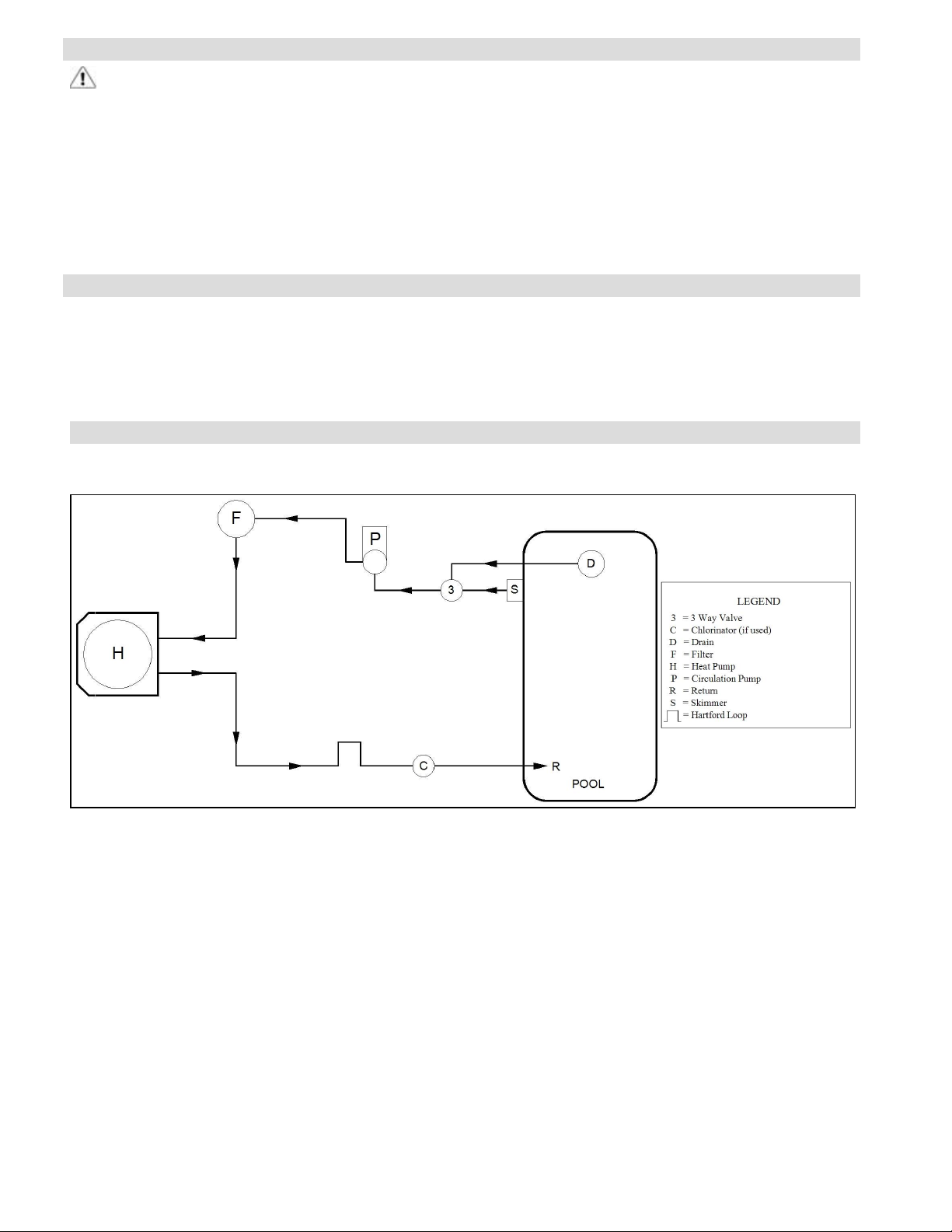
3.3.e Plumbing Diagrams
Plumbing diagrams are provided in this section as a planning guide to the sequence of equipment, valves,
and fittings.
l The basic plumbing configurations for typical installations are shown.
l
If the installation does not closely follow any of the supplied plumbing diagrams, AquaCal®Technical Support is
available for installation advice and guidance.
Air Source Heat Pump Plumbing Diagrams
Heat Pump with water flows equal or less than maximum listed flow rate
See "Water Flow Rates" on page 6.
Page - 9
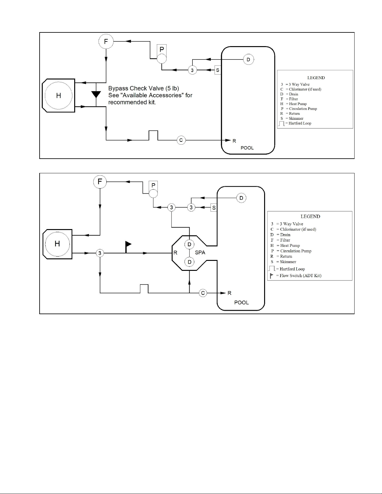
Heat Pump with water flows greater than maximum listed flow rate
See "Water Flow Rates" on page 6.
Heat Pump with Spillover Spa (One filter Pump)
Page - 10
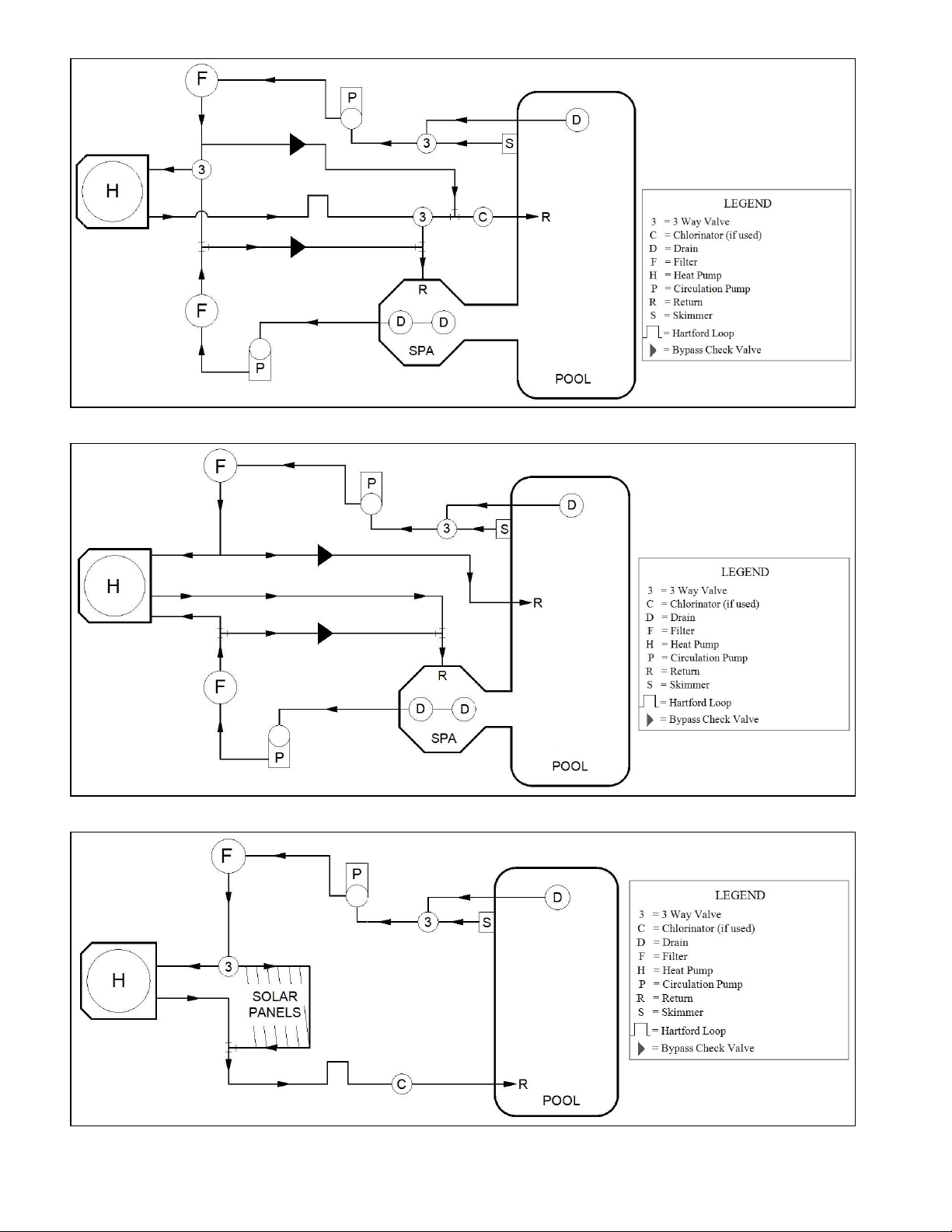
Heat Pump with Spillover Spa (Two filter Pumps)
Heat Pump with Spillover Spa (ATV Installation)
Heat Pump with Solar Panels in Plumbing Circuit
Page - 11
 Loading...