


®
AquaCal
Installation Manual
Important
Read this document before operating / installing this product
For additional product manuals and operation / installation procedures, please visit www.AquaCal.com
LTP0098 REV 2

Table of Contents
Section 1 - Contacting AquaCal AutoPilot, Inc.
Section 2 - Safety
Section 3 - Installation
3.1 Dimensions 3
3.2 Positioning Equipment 5
3.3 Plumbing 5
3.3.a Clearances 5
3.3.b Water Flow Rates 6
3.3.c Adjusting Water Flow Using ΔT (Delta-T) 7
3.3.d Plumbing Requirements 9
3.3.e Plumbing Diagrams 9
3.3.f Water Connections to Heat Pump 12
3.3.g In-Line Chlorine Feeders 13
3.3.h Maintaining Ability to Winterize 13
3.3.i Adjusting Water Pressure Switch 14
3.4 Electrical 14
3.4.a Electrical Requirements 14
3.4.b Electrical Knockouts 16
3.4.c Access Panels 16
3.4.d Schematics 17
3.4.e Verifying Transformer Setting 17
3.4.f Three-Phase Adjustment 17
3.4.g Connecting Heat Pump to an External Controller 18
3.5 Service Level Programming 19
Section 4 - Operation
4.1 Energizing Heat Pump 23
4.2 Display Door 23
4.3 Display Lock 23
4.4 Display Panel 23
4.4.a Buttons 24
4.4.b Indicator Lights 24
4.4.c Display 24
i

4.5 User Level Factory Defaults 25
4.6 Setting Operating Mode 26
4.7 Selecting Celsius or Fahrenheit 26
4.8 Setting Thermostats 26
4.9 User Lock Option (Enable) 27
4.10 User Lock Option (Disable) 28
4.11 User Lock Option (Entering Pass Code) 28
4.12 Operating Heat Pump (With an External Controller) 29
Section 5 - Maintenance
5.1 Water Chemistry 30
5.2 Cleaning Equipment After Installation 30
5.3 Planned Maintenance 31
5.4 Winterizing 32
Section 6 - Troubleshooting
6.1 Fault Codes 34
6.2 Issues and Resolutions 36
Section 7 - Appendix
7.1 Identifying Model Specifications 39
7.2 Weights 40
7.3 Initial Heating Recommendations 40
7.4 Initial Cooling Recommendations 40
7.5 Available Accessories 40
ii
SECTION 1 - CONTACTING AQUACAL AUTOPILOT, INC.
For further assistance, please contact AquaCal AutoPilot, Inc. Technical Support. To better assist you,
please have the heat pump model and serial number available. See "Identifying Model Specifications" on
page 39.
Website www.AquaCal.com
Request Service Online www.AquaCal.com/request-heat-pump-service/
Phone (1) 727-823-5642
Hours 8-5 pm, Eastern M-F
SECTION 2 - SAFETY
l For personal safety, and to avoid damage to equipment, follow all safety instructions displayed on the equipment
and within this manual. Repair and service of heat pump must be performed by an authorized service center.
l Warranties may be voided if the equipment has been improperly installed, maintained or serviced.
l
If service is deemed necessary, please contact AquaCal®Technical Support. See "Contacting AquaCal
AutoPilot, Inc." on page 1.
SAFETY SIGNALS
Throughout this document, safety signals have been placed where particular attention is
required.
WARNING - signals relate to personal safety.
CAUTION - signals promote avoiding damage to the equipment.
When installing and using your heat pump basic safety precautions must always be followed, including the
following:
WARNING - Failure to heed the following may result in injury or death.
l Installation and repairs must be performed by a qualified technician.
l The heat pump contains refrigerant under pressure. Repairs to the refrigerant circuit must not be attempted by
untrained and / or unqualified individuals. Service must be performed only by qualified HVAC technicians.
Recover refrigerant before opening the system.
l The heat pump utilizes high voltage and rotating equipment. Use caution when servicing.
l Electrical installation and service should be performed by a Licensed Electrician only.
l Improper water chemistry can present a serious health hazard. To avoid possible hazards, maintain pool / spa
water per standards detailed in this document.
l Prolonged immersion in water warmer than normal body temperature may cause a condition known as
Hyperthermia. The symptoms of Hyperthermia include unawareness of impending hazard, failure to perceive
heat, failure to recognize the need to exit the spa, and unconsciousness. The use of alcohol, drugs, or medication
can greatly increase the risk of fatal Hyperthermia. In addition, persons having an adverse medical history, or
pregnant women, should consult a physician before using a hot tub or spa. Children and the extreme elderly
should be supervised by a responsible adult.
l Prolonged immersion in water colder than normal body temperature may cause a condition known as
Hypothermia. The symptoms of Hypothermia include shivering (although as hypothermia worsens, shivering
stops), clumsiness or lack of coordination, slurred speech or mumbling, confusion and poor decision-making,
drowsiness or low energy, lack of concern about personal welfare, progressive loss of consciousness, weak
pulse and slow or shallow breathing. In addition, persons having an adverse medical history, or pregnant
women, should consult a physician before immersing in a cold body of water. Children and the extreme elderly
should be supervised by a responsible adult.
Page - 1

CAUTION - Failure to heed the following may result in equipment damage.
l Maintain proper water chemistry in order to avoid damage to pump, filter, pool shell, etc.
l Water flow exceeding maximum flow rate requires a bypass. Damage due to excessive water flow will void
warranty.
SAVE THESE INSTRUCTIONS
Page - 2
SECTION 3 - INSTALLATION
WARNING - Failure to heed the following may result in injury or death.
l Installation of this equipment by anyone other than a qualified installer can result in a safety hazard. The
information contained throughout the "Installation" section is intended for use by qualified installation
technicians familiar with the swimming Pool / Spa safety standards.
CAUTION - Failure to heed the following may result in equipment damage.
l Failure to protect equipment against corrosive conditions will adversely affect the life of the equipment and will
void equipment warranty.
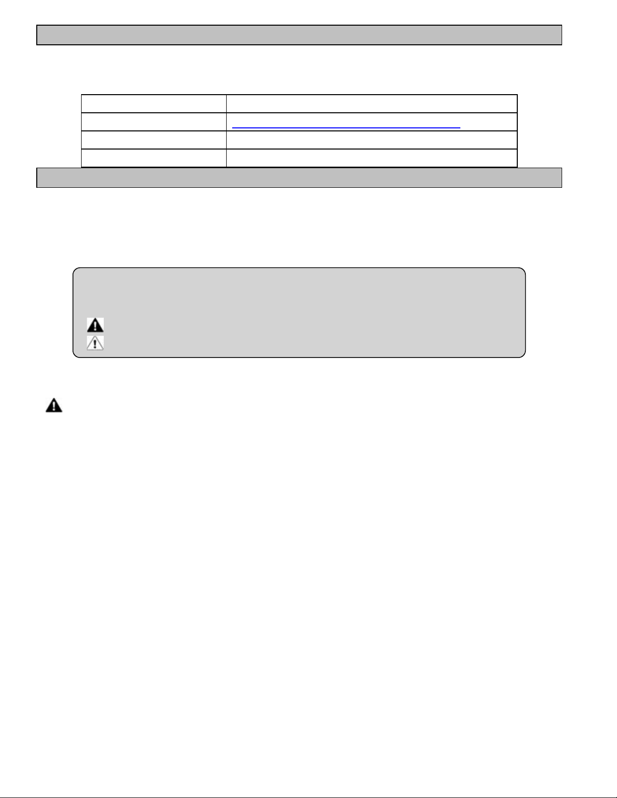
3.1 Dimensions
Dimensions (HeatWave SuperQuiet®SQ120R, SQ125, SQ145, SQ166R and SQ225)
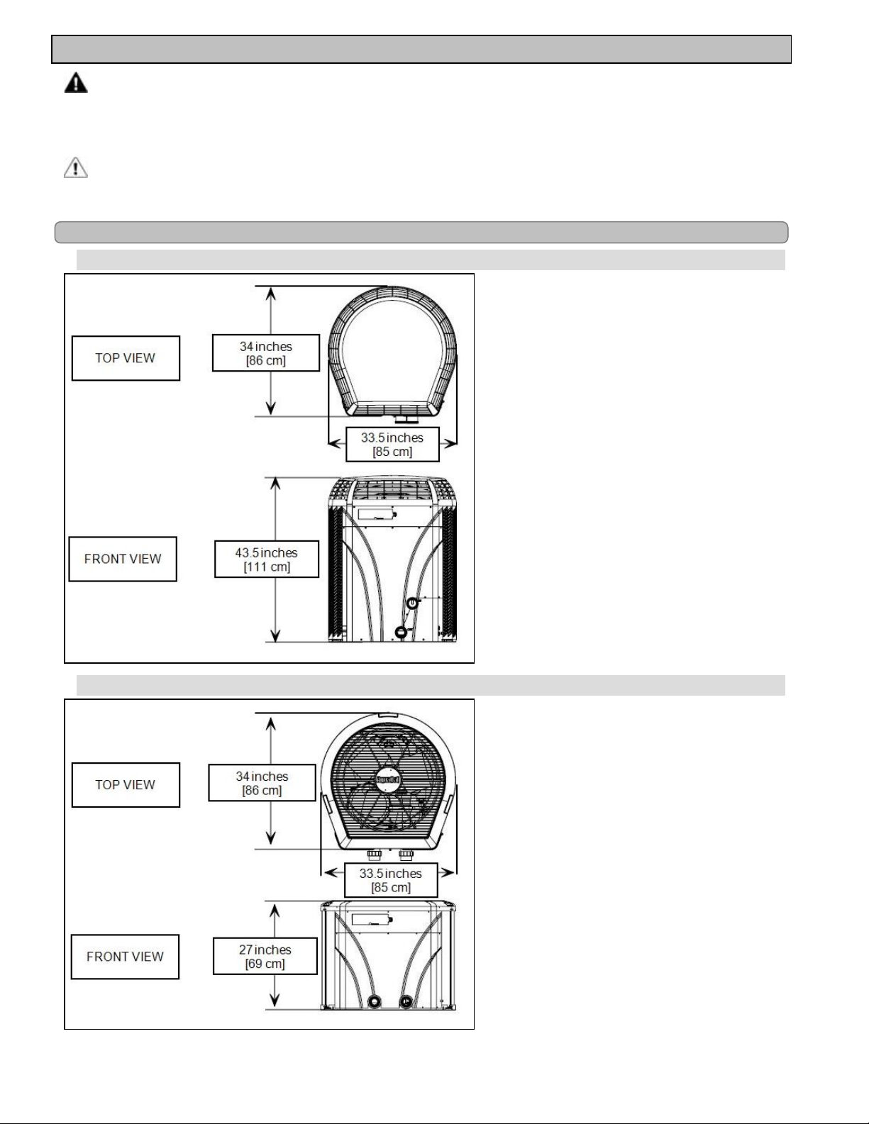
Dimensions (TropiCal®T035, T055 and T075)
Page - 3
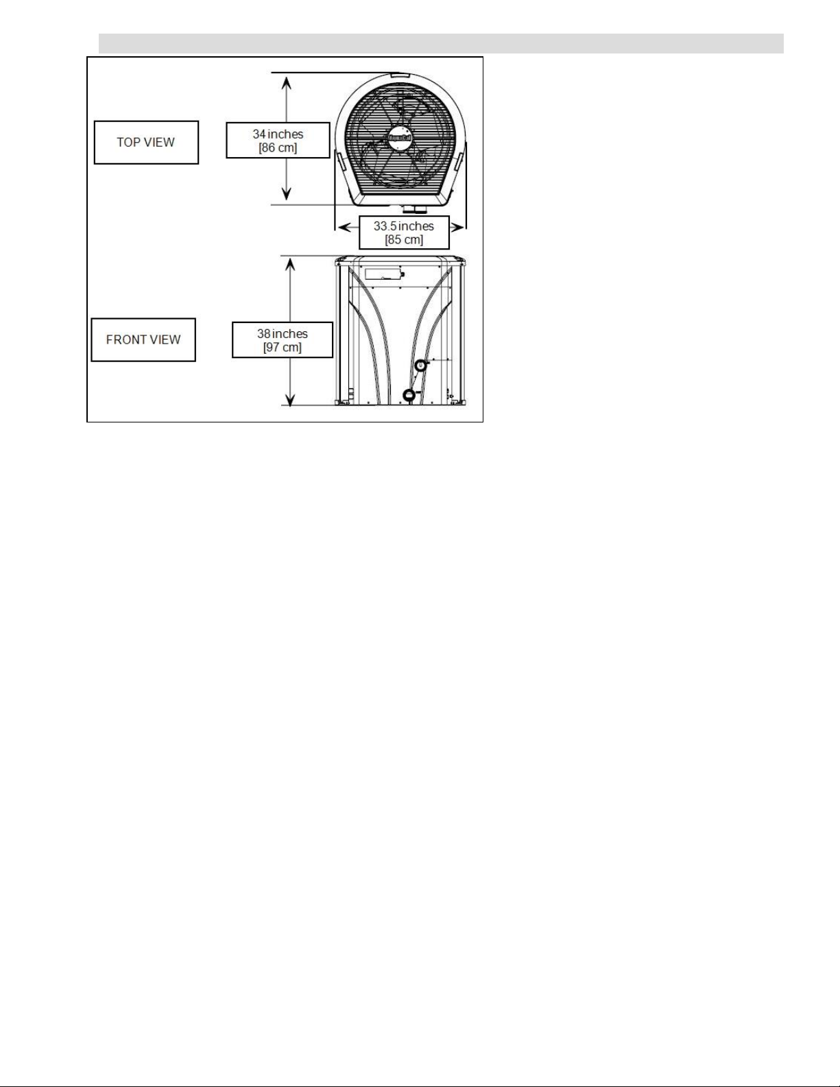
Dimensions (TropiCal®T090, T115 and T135)
Page - 4

3.2 Positioning Equipment
Controlling Irrigation and Rainwater Runoff
l Irrigation water may damage heat pump components. Have irrigation water directed away from the heat pump.
l The heat pump will withstand normal rainfall. Do not allow a roof slope to direct rainwater onto the heat pump.
Have a gutter installed on the roof edge to direct this water away from the heat pump. Or install the heat pump in
another location.
Planning for Condensation
The heat pump can produce a large amount of water in the form of condensation. The amount of water
depends on air temperature and humidity.
l Install the heat pump with enough height to allow for water drainage.
l Plan for water drainage disposal as needed.
Mounting Pad Requirements
l Build the heat pump pad out of concrete or another code-approved material.
l
Confirm the pad can support the weight of the heat pump. See "Weights" on page 40.
l Elevate the pad enough to allow for drainage.
l Make sure the pad is flat and level.
l Have the pad extend at least 6 inches from the heat pump base in all directions.
l Do not install the heat pump on soil or grass.
l Do not allow the heat pump base to touch the buildings foundation.
l Do not place the heat pump directly on a concrete floor inside a building. This can cause noisy equipment
vibration. Install vibration dampeners between the heat pump base and floor.
l Equipment pad must meet all requirements of authorities having code-related jurisdiction.
Anchoring to Pad
l Follow all applicable local, state, and national requirements regarding wind load anchoring.
l The shipping brackets used to tie the heat pump to the pallet are approved mounting (hurricane) brackets. They
can be used to anchor the heat pump to the pad.
l
If needed, contact AquaCal®Customer Support to obtain the correct anchoring kit information. Please have the
heat pump model number and serial number when requesting support. See "Identifying Model Specifications" on
page 39.
3.3 Plumbing
3.3.a Clearances
l Proper air circulation is required for the heat pump to operate efficiently. Avoid placing objects near or on top of
the heat pump. This includes shrubbery and lawn furniture. These objects will also hinder maintenance access.
l Avoid storing chemical containers near the heat pump. The chemicals can cause equipment damage.
Page - 5
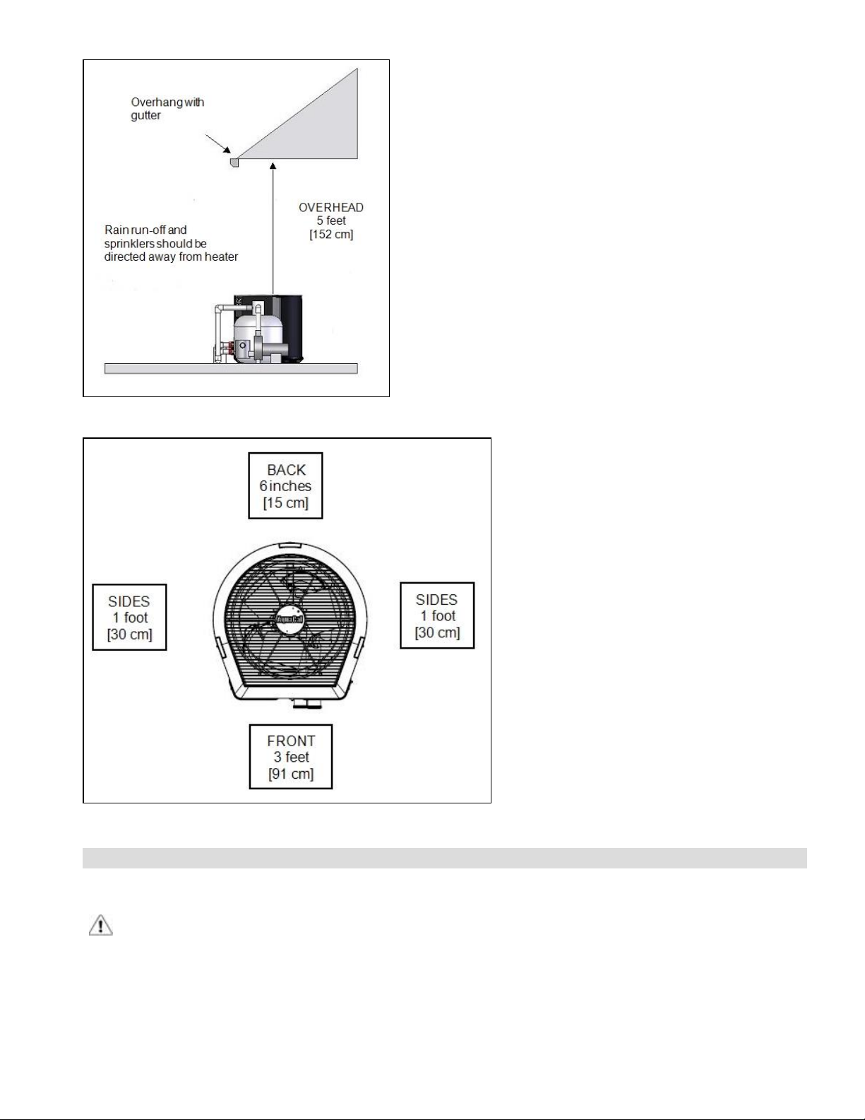
Overhead Clearance
HeatWave SuperQuiet®and TropiCal®(Top View)
3.3.b Water Flow Rates
Maintain water flow rates as indicated. Please note, these specifications relate to the heat pump only. Codespecified whole system turnover rates must be satisfied.
CAUTION - Failure to heed the following may result in equipment damage.
l Water flow exceeding maximum flow rate may damage heat exchanger; such damage will not be covered under
the equipment warranty
Page - 6

SQ120R
SQ125
SQ145
SQ166R
SQ225
MODEL HEAT EXCHANGER TYPE
Titanium ThermoLink
Titanium ThermoLink
Titanium ThermoLink
Titanium ThermoLink
Titanium ThermoLink
®
®
®
®
®
FLOW RATES
MINIMUM MAXIMUM
30 GPM 70 GPM
30 GPM 70 GPM
30 GPM 70 GPM
30 GPM 70 GPM
30 GPM 70 GPM
T035
T055
T075
T090
T115
T135
Titanium Tube-in-Tube 20 GPM 45 GPM
Titanium Tube-in-Tube 20 GPM 45 GPM
Titanium Tube-in-Tube 20 GPM 45 GPM
Titanium ThermoLink
Titanium ThermoLink
Titanium ThermoLink
®
®
®
30 GPM 70 GPM
30 GPM 70 GPM
30 GPM 70 GPM
If water flow through the heat pump is reduced, performance will suffer and internal safety devices may
deactivate the heat pump with error codes HP and HP5, or (if equipped) an LP and LP5.
l Operate water filtration devices per manufacturer's specifications. Dirty filters can cause reduced water flow to the
heat pump. An increase of 7-10 psi higher than the clean filter pressure typically reduces flow rates. This requires
the filter to be cleaned or back-washed
l Keep baskets free of debris. Similar to a dirty filter, large volumes of debris in the pump and skimmer baskets can
reduce water flow.
l Check for improper valve settings. A partially closed valve after the filter, or a full-open bypass around the heat
pump, will cause insufficient water flow through the heat pump.
l The maximum static (or operating pressure) is 50 pounds-per-square-inch (PSI). These specifications relate to the
heat pump only. Code-specified whole system turnover rates must be satisfied.
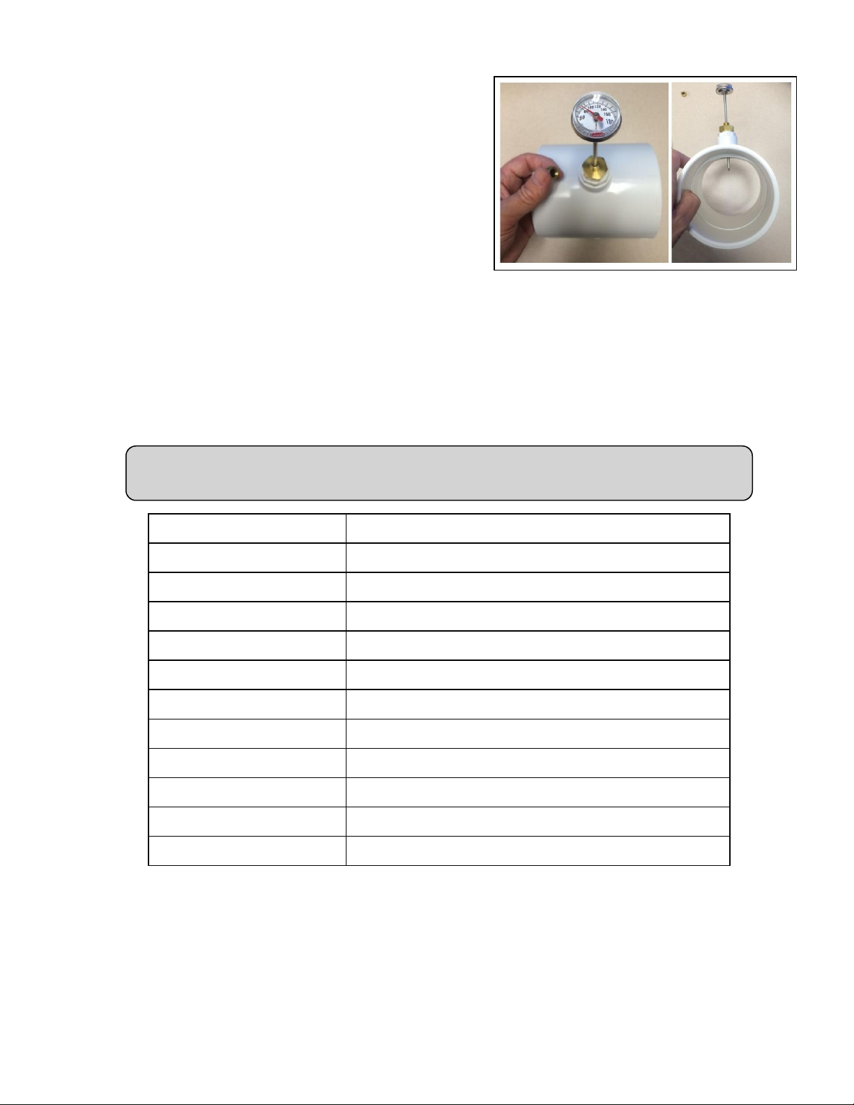
3.3.c Adjusting Water Flow Using ΔT (Delta-T)
The Delta-T is the temperature difference between the water temperatures entering and leaving the heat
pump. The equipment can be fine-tuned for maximum performance by balancing water flow rates to
maintain an ideal ∆T.
l Installed Temperature / Pressure probes and ports are required to perform the following procedures.
l
This adjustment procedure is to be completed with the unit in HEA mode only; ACH and COO discharge
temperatures are not shown.
PLEASE NOTE -
Temperature / Pressure ports are required for all commercial applications.
They are strongly recommended (but not required) for residential installations.
Page - 7
1.
Adjust heat pump thermostat to its lowest setting while in
HEA mode.
2.
Deactivate the water filtration pump.
3.
Adjust valves to a halfway open position leading to the
heat pump.
4.
Adjust valves to a fully open position leading away from
the heat pump.
5.
Activate the pool water filtration pump.
6.
Slowly turn the thermostat up until the heat pump
activates.
l After a four-minute delay, the heat pump
compressor will start.
7.
With the heat pump running, confirm water filtration
pump is operating properly with adequate flow and no
short cycling. If needed, clean filters leading to the heat pump.
8.
Wait for water and refrigerant pressure to stabilize (approximately 5 minutes).
9.
Adjust valves in the following order:
A.
Adjust valve leading away from the heat pump to correct temperatures measured with a temperature
pressure probe.
B.
Allow pressure to stabilize . Then check temperature again. Re-adjust valve leading away from the
heat pump as needed.
10.
Mark valves at these positions for future reference.
Temperature / Pressure Port
(Shown with Probe)
Temperature differences are based on pool temperatures of 72° (+ or – 3° F). For water
temperatures outside this range, contact AquaCal®Technical Support.
MODEL TEMPERATURE
SQ120R 3° to 7° F
SQ125 3° to 7° F
SQ145 3° to 7° F
SQ166R 3° to 8° F
SQ225 4° to 9° F
T035 1° to 4° F
T055 2° to 5° F
T075 3° to 7° F
T090 3° to 6° F
T115 3° to 7° F
T135 4° to 8° F
Table 1 - Temperature Chart
Page - 8
3.3.d Plumbing Requirements
CAUTION - Failure to heed the following may result in equipment damage.
l Do not use glue on the threaded portion of the equipment’s unions. A glued-in-place union will prevent the
equipment from being properly winterized.
l The heat pump must receive water flow within the specified minimum ranges under worst-case conditions such
as a fouled water filter.
l Water flow exceeding maximum flow rates may damage heat pump and will not be covered under equipment
warranty. See "Water Flow Rates" on page 6.
l Install a bypass valve whenever water-flow may exceed maximum rating.
l See "5 lb Bypass Valve Kit (Kit STK0135)" on page 40.
l
For additional guidance testing water flow rates, please contact AquaCal®Technical Support.
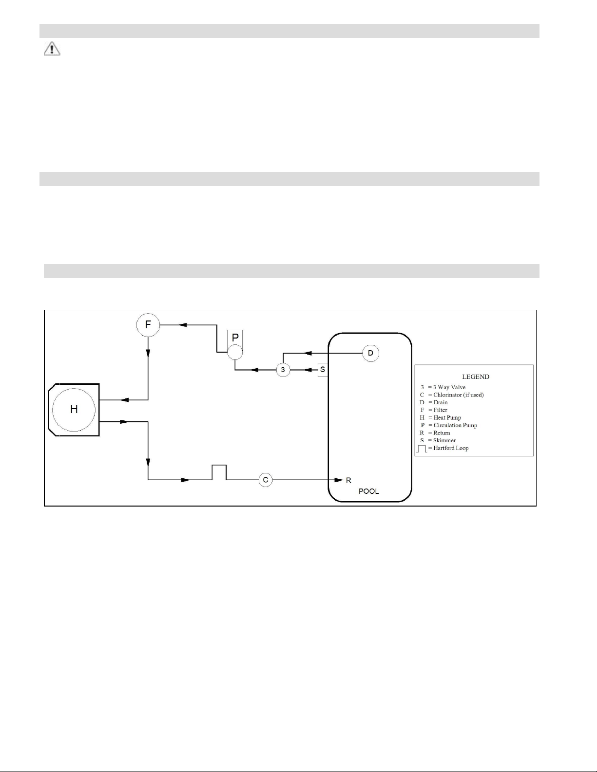
3.3.e Plumbing Diagrams
Plumbing diagrams are provided in this section as a planning guide to the sequence of equipment, valves,
and fittings.
l The basic plumbing configurations for typical installations are shown.
l
If the installation does not closely follow any of the supplied plumbing diagrams, AquaCal®Technical Support is
available for installation advice and guidance.
Air Source Heat Pump Plumbing Diagrams
Heat Pump with water flows equal or less than maximum listed flow rate
See "Water Flow Rates" on page 6.
Page - 9
Heat Pump with water flows greater than maximum listed flow rate
See "Water Flow Rates" on page 6.
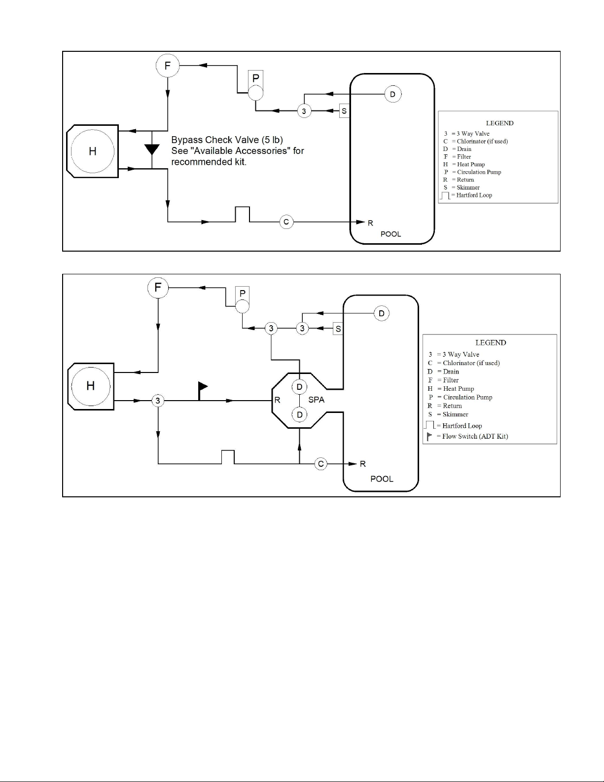
Heat Pump with Spillover Spa (One filter Pump)
Page - 10
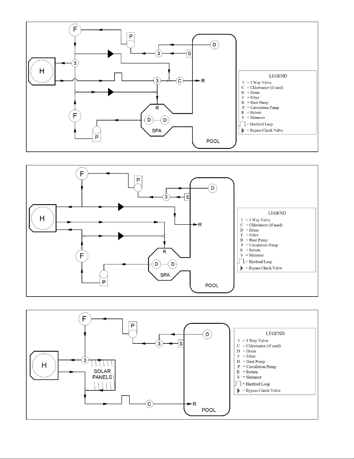
Heat Pump with Spillover Spa (Two filter Pumps)
Heat Pump with Spillover Spa (ATV Installation)
Heat Pump with Solar Panels in Plumbing Circuit
Page - 11

Heat Pump with Gas Heater backup
Multiple Air Source Heat Pumps
3.3.f Water Connections to Heat Pump
l Connections to site plumbing are made via PVC solvent cement to the female slip socket of the plumbing unions.
l Heat Pump union sizes are specified on diagrams.
l
Plumbing unions are available from AquaCal®. See "Available Accessories" on page 40.
CAUTION - Failure to heed the following may result in equipment damage.
l Do not use glue on the threaded portion of the equipment’s unions. A glued-in-place union will prevent the
equipment from being properly winterized.
Page - 12

TropiCal®T035, T055, T075, TropiCal®T090, T115, T135
HeatWave SuperQuiet®SQ120R, SQ125, SQ145, SQ166R,
SQ225
3.3.g In-Line Chlorine Feeders
Place in-line chlorinators downstream from the heat pump and as low in elevation as possible. If an erosion
type feeder is used, always install a Hartford Loop to protect internal heat pump components.
Heat Pump with Hartford Loop
3.3.h Maintaining Ability to Winterize
CAUTION - Failure to heed the following may result in equipment damage.
l Do not use glue on the threaded portion of the equipment’s unions. A glued-in-place union will prevent the heat
pump from being properly winterized.
The unions can be used to decouple the heat pump from the plumbing system during hard freeze conditions.
Do not defeat the function of the unions by using glue on the threaded portion of the unions. See
"Winterizing" on page 32.
Page - 13

3.3.i Adjusting Water Pressure Switch
Adjust water pressure switch when heat pump attempts to operate without water flow.
WARNING - Failure to heed the following may result in injury or death.
l Water Pressure Switch adjustment procedure to be performed by experienced service personnel only; procedure
must not be attempted by individuals lacking adequate electrical and mechanical experience.
CAUTION - Failure to heed the following may result in equipment damage.
l If after water pressure switch adjustment the heat pump continues to operate with the filter pump off, readjust
water pressure switch to ensure heat pump will not run without water flow.
Confirm the following before attempting any adjustments:
l The filter is clean.
l Filter pump is operating.
l
Valves are set to direct appropriate amount of water through the heat pump. See "Water Flow Rates" on page 6.
l
FLO code is displayed (or displays intermittently).
Adjusting Water Pressure Switch:
1. Remove heat pump access panel. See "Access Panels"
on page 16.
2.
Locate the water pressure switch. It will be outside and
along the bottom edge of the electrical enclosure. Exact
location varies by model.
3.
Activate filter pump.
4.
Apply power to heat pump.
5.
Slowly rotate adjustment wheel on switch until the FLO
code just disappears.
6.
Deactivate filter pump. If correctly adjusted, theheat
pump will deactivate and display FLO.
7.
Re-install heat pump access panel.
l
If heat pump continues to operate without water flow, contact AquaCal®Technical Support.
l
Site-specific factors may require the installation of an external flow switch. See "Available
Accessories" on page 40.
3.4 Electrical
3.4.a Electrical Requirements
WARNING - Failure to heed the following may result in injury or death.
l The information contained in this section is intended for use by qualified electricians familiar with electrical
service-industry safety standards and methods.
l Locate the equipment disconnect as near to the heat pump as possible. Always satisfy applicable codes and
standards.
l Never mount power-disconnects directly to the heat pump.
l In sizing power wiring, be especially aware of up-sizing requirements necessary due to wiring distances. Always
satisfy applicable codes and standards.
l Multiple heat pumps installed at the same site may benefit from automatic sequencing controllers (ASC) to
avoid excessive power drops at start-up. See "Available Accessories" on page 40.
l
AquaCal®heat pumps are designed to use copper conductors, only. Do not use aluminum wire.
Page - 14

Electrical Standards
Standards Title
NFPA 70
NFPA 70 Article 440
NFPA 70 Article 680
IEC 60335-1-2001
IEC 60335-2-40 2006
UL1995 & CSA C22.2
236-05
Table 2 - Standards
Grounding and Bonding
The electrical installation must conform to the current
version of the NEC, and all applicable local and state
codes
Standard for Safety for Electric Spas, Equipment
Assemblies, and Associated Equipment
Standard for Safety for Swimming Pool Pumps, Filters,
and Chlorinators
Household and similar electrical appliances - Safety General Requirements
Household and similar electrical appliances - Safety –
Particular requirements for electrical heat pumps, airconditioners, and dehumidifiers
Heating and cooling equipment
Follow local code requirements for properly grounding and bonding heat pump equipment.
l A bonding lug has been provided on the lower right hand corner of the front panel.
Surge Suppression
The use of approved commercial surge protectors is strongly recommended.
Sizing the Electrical Service
Refer to equipment data plate for specific information required to size electrical service and over-current
protection of heat pump. Sizing is based on data plate information, wire size, wiring devices, and overcurrent protection per applicable local codes and standards. See "Identifying Model Specifications" on page
39.
Page - 15

3.4.b Electrical Knockouts
HeatWave SuperQuiet®and TropiCal
®
TC500 TC1000
3.4.c Access Panels
Access Panels (HeatWave SuperQuiet®) and (TropiCal®)
Page - 16

3.4.d Schematics
Schematics are located on the inside of the equipment access panel.
PLEASE NOTE:
l Specifications are subject to change without notice.
l
Schematics are available by calling AquaCal®Customer Support.
l Please have the complete model and serial number available.
l
See "Identifying Model Specifications" on page 39.
3.4.e Verifying Transformer Setting
Transformer voltage settings must be confirmed and set correctly depending on the measured voltage found
on the site. Incorrect settings may cause heat pump damage. The following procedure will allow the installer
to set the heat pumps transformer for the appropriate site voltage.
WARNING - Failure to heed the following may result in injury or death.
l The information contained in this section is intended for use by qualified electrical installation technicians,
familiar with electrical service-industry safety standards and methods.
CAUTION - Failure to heed the following may result in equipment damage.
l Setting a voltage other than what is listed on the heat pump's data plate can damage equipment and is not covered
under warranty.
1.
Turn heat pump on by adjusting the thermostat to call for heating or
cooling. If more than one heat pump is on site, turn them all on. Final
adjustments must be made with all heat pumps running.
2.
Measure the running site voltage.
3.
Confirm transformer tap is set for the measured site voltage. If more than
one voltage tap is shown, select the voltage nearest to the running site
voltage.
Example of heat pump
transformer
(Varies between models)
Please note: If more than one voltage is shown on the equipment’s data plate, the factory
default setting is usually the higher voltage on the transformer. As an example, a
"208/230" voltage will be set to "240" from the factory.
3.4.f Three-Phase Adjustment
If a three-phase unit fails to operate at start up, the orientation of the line voltage "field" wiring may need to
be adjusted.
WARNING - Failure to heed the following may result in injury or death.
l The information contained in this section is intended for use by qualified electrical installation technicians,
familiar with electrical service-industry safety standards and methods.
CAUTION - Failure to heed the following may result in equipment damage.
l Setting a voltage other than what is listed on the heat pump’s data plate can damage equipment and is not
covered under warranty.
1. Deactivate power to the unit. Confirm that power is off to all three legs using an electrical test meter
set for the correct voltage.
Page - 17

2.
Switch position of the incoming power wires at each leg as follows, re-connect power, and attempt to restart
the unit. If the unit fails to start, disconnect power. Verify off and proceed to next leg.
l Switch incoming power wires at L1 and L2 on the line side to the contactor.
l Switch incoming power wires at L1 and L3 on the line side to the contactor.
l Switch incoming power wires at L2 and L3 on the line side to the contactor.
3.
When heat pump starts, disconnect power and verify off. Then confirm all line voltage connections are
securely tightened. Reconnect power.
l
If heat pump does not start, contact AquaCal®Technical Support.
3.4.g Connecting Heat Pump to an External Controller
To support a direct connection to an external controller, AquaCal®heat pumps are equipped with optional
terminal blocks. These terminals are on the microprocessor located on the low-voltage side of the electrical
enclosure.
WARNING - Failure to heed the following may result in injury or death.
l This section is only for qualified installers who are familiar with swimming pool and spa safety standards.
l The installer must be familiar with service industry techniques.
l Deactivate power while routing wiring to control board.
CAUTION - Failure to heed the following may result in equipment damage.
l The wire size connecting the controller must be 16-gauge, 2-conductor or larger, low-voltage wire.
l
Use direct connection (dry contact) provided on the microprocessor for external controllers.
Please confirm the type of external controller to be installed and follow the
appropriate instructions.
l
A two-wire controller (with an internal thermostat). The user can set and
adjust the temperature at the controller's screen.
l
A three-wire controller (with an "OFF" position). The user adjusts the
temperature at the heat pump. The user can select pool or spa mode or turn
off the heat pump using the controller.
l
A three-wire controller (without an "OFF" position). The user adjusts
the temperature at the heat pump. The user can select pool or spa mode,
but must turn off the heat pump at the heat pump display panel.
Dry Contact Connection
Points to the Microprocessor
Figure 1
Two-wire controller (with internal thermostat):
1.
Deactivate power to heat pump.
2.
Remove heat pump electrical access panel.
3.
Route the control wiring to the low voltage side of the electrical enclosure. Follow all National Electric Codes
(NEC) unless State or Local guidelines supersede.
4.
Connect the controller wires to the microprocessor as follows:
l
Connect one wire to “Y”. See Figure 1.
l Connect other wire to “Z”.
l The polarity of the wire is not important.
5.
Reattach heat pump access panel.
6.
Apply power to heat pump.
7. Program heat pump for a two-wire controller. See "Using JAO interface" on page 20.
8. Test external controller. See "Operating Heat Pump (With an External Controller)" on page 29.
Page - 18

Three-wire controller (with "OFF" position):
1.
Deactivate power to heat pump.
2.
Remove heat pump electrical access panel.
3.
Route the control wiring to the low voltage side of the electrical enclosure. Follow all National Electric Codes
(NEC) unless State or Local guidelines supersede.
4.
Connect the controller wires to the microprocessor as follows:
l
Connect "High" or "Spa" wire to "X". See Figure 1.
l Connect "Common"wire to "Y".
l Connect "Low"or "Pool" wire to "Z".
5.
Reattach heat pump access panel.
6.
Apply power to heat pump.
7. Program heat pump for a three-wire controller. See "Using JAO interface" on page 20.
8. Test external controller. See "Operating Heat Pump (With an External Controller)" on page 29.
Three-wire controller (without an "OFF" position):
1.
Deactivate power to heat pump.
2.
Remove heat pump electrical access panel.
3.
Route the control wiring to the low voltage side of the electrical enclosure. Follow all National Electric Codes
(NEC) unless State or Local guidelines supersede.
4.
Connect the controller wires to the microprocessor as follows:
l
Connect "Common" wire to one terminal of "FS2". See Figure 1.
l Connect "Spa" to other terminal of "FS2".
l The third wire is not used.
5.
Reattach heat pump access panel.
6.
Apply power to heat pump.
7. Program heat pump for an external controller. See "Using FS2 interface" on page 21.
8. Test external controller. See "Operating Heat Pump (With an External Controller)" on page 29.
3.5 Service Level Programming
CAUTION - Failure to heed the following may result in equipment damage.
l Service Level Programming must only be attempted by authorized personnel.
l
Unauthorized adjustments in the Service Menu (beyond the LOC menu) may void the heat pump's warranty.
l Resetting the microprocessor to access a locked keypad will reset all settings to factory default including any
installer-entered configuration. Re-programming all custom site condition settings will be required when using
this reset. See "Reset to Factory Defaults Settings" on page 22.
l
For further assistance, please contact AquaCal®Technical Support. See "Contacting AquaCal AutoPilot, Inc."
on page 1.
PLEASE NOTE -
Before changing multiple program options, it is recommended that the user lock option be
disabled. See "User Lock Option (Disable)" on page 28.
The lockout option can be re-enabled after all changes are completed.
Service Level Factory Defaults
Certain programming options have been preset at the factory. These options can be overwritten for certain
site-specific conditions.
Page - 19

Table 3 - Default Program Parameters Chart
CODE DESCRIPTION
CFO
dBP
dB5
DEL
dSC
dFd
FS2
Call-Flex Options 0 Set to off at the factory.
Pool Dead-Band Differential 1°
Spa Dead-Band Differential 1°
Compressor Time Delay 1 (4 minutes)
Defrost Sensor
Defrost Delay
Flow Switch / Automatic
Thermostat Switching
Option
DEFAULT
VALUE
Factory
Calibrated
Factory
Calibrated
0
RANGE
Set at factory. Do not
adjust.
Set at factory. Do not
adjust.
Set to on (at 4 minutes) at
the factory. Do not adjust.
Set at factory. Do not
adjust.
Set at factory. Do not
adjust.
0 = "No Switch"
1 = "Enable Switch"
JAO
LOC
tSC
Programming for an External Controller
Configure heat pump for external control.
Using JAO interface
Press "Up" and
"Down" buttons
simultaneously
until CF1 appears.
External Controller 0
Service Level Entry Point 50 00 - 99
Water Sensor
Press "Pool / Spa"
button until LOC
is displayed.
0 = "No Controller"
2 = "Two Wire
Controller"
3 = "Three Wire
Controller"
Factory
Calibrated
Press "Up" or
"Down" to
passcode. Default
is "17".
Set at factory. Do not
adjust.
Press "Pool / Spa"
button once.
Page - 20

Press the "Pool /
Spa" button until
JAO is displayed.
Using FS2 interface
Press "Up" or
"Down"button.
l "0" - none
l "2" - two-wire
l "3" - three-wire
Press "Up" and
"Down" buttons
simultaneously
until CF1 appears.
Press the "Pool /
Spa" button until
FS2 is displayed.
Press "Pool / Spa"
button until LOC
is displayed.
Press "Up" or
"Down" button.
l "0" - none
l "1" - External
Press "Up" or
"Down" to
passcode. Default
is "17".
Press "Pool / Spa"
button once.
Page - 21

Programming for a Relay Switch
Configure heat pump for a relay or flow switch. This can provide automatic pool/ spa thermostat switching.
Press "Up" and
"Down" buttons
simultaneously
until CF1 appears.
Press the "Pool /
Spa" button until
FS2 is displayed.
Once the FS2 feature has been activated the "POOL / SPA" button will no longer
function. The relay or flow switch is used to change between the pool and spa temperature
settings.
Press "Pool / Spa"
button until LOC
is displayed.
Press the "Up" or
"Down"
l "0" - not active
l "1" - enable
Press "Up" or
"Down" to
passcode. Default
is "17".
Press "Pool / Spa"
button once.
Reset to Factory Defaults Settings
CAUTION - Failure to heed the following may result in equipment damage.
l
Using this option will reset ALL settings to their factory defaults including external controller
settings and sensor calibrations. DO NOT perform this operation if unsure of site specific settings or
how to reset them on the heat pump.
l
If a qualified technician is unavailable, please contact AquaCal®Technical Support. See "Contacting AquaCal
AutoPilot, Inc." on page 1.
1.
Simultaneously Press "Pool / Spa" button and "Up"
button until the display shows 888.
2.
Release buttons. Reset is complete.
Page - 22

SECTION 4 - OPERATION
4.1 Energizing Heat Pump
Turn power on at external fuse box or breaker disconnect.
l Controller performs a lamp test.
l
The display reads 888.
l
Controller then displays as normal. See "Display" on page 24.
4.2 Display Door
The display panel is located in a door compartment on the front of the heat pump. This compartment is
designed to protect the display against harsh weather. It can also be padlocked for extra security.
l Press the bottom of the
panel to open the
display panel door.
l To close, push the
display panel up. Then
press the bottom of the
panel in until a clicking
noise is heard.
4.3 Display Lock
The heat pump has a display lock to protect against
inadvertent setting changes. To activate display and
controls, slide finger across the controls as shown from
left to right.
l
The code UnL will briefly appear, then the set temperature
or mode will display.
l This is different than a user-lock which requires a pass
code. See "User Lock Option (Enable)" on page 27.
4.4 Display Panel
The following information outlines the operation for a standard installation.
l Control Buttons will operate differently for custom installations; such as a
heat pump connected to an external controller. See "Operating Heat Pump
(With an External Controller)" on page 29.
Display Panel
Page - 23

4.4.a Buttons
Buttons Description
Display Lock
Pool / Spa Select either the pool or the spa thermostat.
Up Arrow
Down Arrow
Mode Select heat pump's operating mode.
4.4.b Indicator Lights
Indicators Description
Pool The Heat Pump is referencing the pool thermostat.
Spa The Heat Pump is referencing the spa thermostat.
Heating
Cooling
Sliding your finger across the buttons from left to right will
temporarily disable the display lock.
Used to increase temperature set point and navigate
though menu options.
Used to decrease temperature set point and navigate
though menu options.
Indicates the unit is heating the water.
Please note - the compressor must be operating before this
light will illuminate.
Indicates the unit is cooling the water.
Please note - the compressor must be operating before this
light will illuminate.
Water Temp Indicates current water temperature.
Desired Temp
4.4.c Display
75
FLO
OFF
888
Indicates temperature set point is displayed. This is
displayed when "UP" or "DOWN" is selected.
Display Description
The heat pump is on and displaying the current water
temperature. In this example 75° F is displayed.
No water flow is detected. The filter pump is off or heat
pump is not receiving correct water flow.
The heat pump has been turned off via the mode selector
button or the temperature set point has been lowered
below 45° F.
The control program is initializing. This displays only as
power is applied to the heat pump. The program version
number will then be displayed.
Page - 24

Display Description
CF1
Select water temperature format (in either Celsius or
Fahrenheit).
ULC
ELC
Enable heat pump lockout feature.
Select passcode to lock the keyboard.
This is a Service Entry Point (not intended for use by the
owner). The LOC code permits service personnel to enter a
LOC
factory passcode to access adjustable calibration and site
dependent setup parameters. Service adjustments are
available to authorized installation and service personnel,
only.
4.5 User Level Factory Defaults
Certain programming options have been preset at the factory. These options can be overwritten for sitespecific conditions.
CAUTION - Failure to heed the following may result in equipment damage.
l
Unauthorized adjustments in the Installer Menu (beyond the LOC menu) may void heat pump's warranty.
Table 4 - Factory Defaults
CODE DESCRIPTION
DEFAULT
VALUE
RANGE
OFF
HEA
COO
ACH
CF1
ELC
ULC
Heat Pump is
deactivated.
Set to heat water
to point set on
thermostat.
Set to cool water
to point set on
thermostat.
Set to maintain a
water temperature
set on the
thermostat.
Celsius /
Fahrenheit
Selection
1
0 = Celsius
1 = Fahrenheit
Enter Lock Code 0 0 - 99
User Lock Code 0
0 = "User Lock Disabled"
1 = "User Lock Enabled"
Page - 25

4.6 Setting Operating Mode
Heat
Mode
Cool
Mode
Heating / Cooling modes only available
on select equipment. Confirm heat pump
features before setting a mode.
4.7 Selecting Celsius or Fahrenheit
Automatic
Heat / Cool Mode
Deactivate
Heat Pump
Hold "UP" and
"DOWN" until
CF1 displays.
4.8 Setting Thermostats
Select "POOL" or
"SPA"
Press "UP or
"DOWN" button
to select.
"0" - Celsius
"1" - Fahrenheit
Press "UP" or
"DOWN" to the
desired
temperature.
l The heating
indicator will
illuminate when
heating the
water.
l The cooling
indicator will
illuminate when
cooling the
water.
Page - 26

4.9 User Lock Option (Enable)
The user-lock feature allows the heat pump display panel to be "locked". This can prevent unauthorized
temperature adjustments in commercial applications.
l
Do not confuse a user-lock with the display lock. See "Display Lock" on page 23.
l
If LOC is briefly displayed, followed by a "0", the heat pump is already locked.
l
If the user-lock code has been misplaced, please contact AquaCal®Customer Service for
further assistance.
Hold "UP" and
"DOWN" until
CF1 displays.
Press "POOL /
SPA" button until
ULC is displayed.
Press "POOL /
SPA" button until
ELC is displayed.
Press "Up" button
till "1" is
displayed to
enable.
Press "UP or
"DOWN" button to
change or add a
numerical password
Press "POOL /
SPA" button to
lock in the
password.
Page - 27

4.10 User Lock Option (Disable)
Use "UP" button
to enter existing
password.
Press "Pool / Spa"
button to unlock.
Hold "UP" and
"DOWN" buttons
until CF1 is
Press "POOL /
SPA" button until
ULC is displayed
displayed.
Press "DOWN"
button until "0" is
displayed.
4.11 User Lock Option (Entering Pass Code)
If LOC is briefly displayed when attempting to change a heat pump's settings followed by a "0", the heat
pump is in a user-lock mode. A numerical passcode is required to proceed.
Press "UP" or
"DOWN" arrow
to enter user lock
code.
NOTE -
l
After three seconds of inactivity, the heat pump's display lock will activate. See "Display
Lock" on page 23.
l
If the user-lock code has been misplaced, please contact AquaCal®Customer Service for
further assistance.
Press "POOL /
SPA" button to
unlock.
Page - 28

4.12 Operating Heat Pump (With an External Controller)
Controller with an internal thermostat control
Activating Heat Pump
1.
Set the desired temperature at the external controller.
2.
Use the external controller to select either the "Pool" or "Spa" to heat.
Deactivating Heat Pump
l Set the external controller to "OFF".
Please note - If equipped, the heat pump's cooling function will be disabled when using
this type of controller.
If the cooling function is needed, the heat pump must be temporarily re-programed for
local control.
l Set the heat pump to operate with external control temporarily set to "none".
l
See "Programming for an External Controller" on page 20.
l It is ok to leave external controller wires in place while the heat pump is set for local control.
Controller with 2 positions - ("Pool"and "Spa" - no internal thermostat control)
Activating Heat Pump
1. Set the desired temperatures on the heat pump thermostats. See "Setting Thermostats" on page 26.
2.
Use the external controller to select either the "Pool"or "Spa" to heat.
l Rapid movement between thermostats without a "rest"between each change can cause a missed signal
by the heat pump.
Deactivating Heat Pump
l
Go to the heat pump and set the mode to "OFF". See "Setting Operating Mode" on page 26.
Please note - If equipped, the heat pump's cooling function will be disabled when using
this type of controller.
If the cooling function is needed, the heat pump must be temporarily re-programed for
local control.
l Set the heat pump to operate with external control temporarily set to "none".
l
See "Programming for an External Controller" on page 20.
l It is ok to leave external controller wires in place while the heat pump is set for local control.
Controller with 3 positions - ("High", "Low", and "Off" - no internal thermostat control):
Activating Heat Pump
1. Set the desired temperatures on the heat pump thermostats. See "Setting Thermostats" on page 26.
2.
Use the external controller to select either "High"or "Low" to heat.
l When changing between thermostats, select "Off" first. Then select desired thermostat.
l Rapid movement between thermostats without a "rest"between each change can cause a missed signal
by the heat pump.
Deactivating Heat Pump
l Set the external controller to "OFF".
Page - 29

SECTION 5 - MAINTENANCE
5.1 Water Chemistry
Check water chemistry regularly and maintain within recommended levels. Standards for commercial
applications vary in different areas. Follow all local applicable codes.
CAUTION - Failure to heed the following may result in equipment damage.
l Do not allow water to flow through heat pump when refinishing or acid washing a pool. Either use an installed
bypass to route water away from heat pump or deactivate filter pump.
l To avoid damage to equipment, monitor and maintain chemistry within recommended levels.
CHEMISTRY LEVEL CHART
(RESIDENTIAL)
CHEMICAL POOLS SPAS
Chlorine 1.0 – 3.0 ppm 3.0 – 5.0 ppm
Bromine 2.0 – 6.0 ppm 2.0 – 6.0 ppm
Cyanuric
Acid
30 - 50 ppm 30 - 50 ppm
pH 7.4 – 7.6 ppm 7.4 – 7.6 ppm
Total
Alkalinity
Calcium
Hardness
Total
Dissolved
Solids
•
•
Salt from a chlorine generator is not included in Total Dissolved Solids.
80 – 120 ppm 80 – 120 ppm
200 – 400
ppm
0 – 1,500 ppm
150 – 250 ppm
1,500 ppm above start-up total dissolved solids in
spas
5.2 Cleaning Equipment After Installation
Installer - If you need to clean equipment after installation, please use the following guidelines.
WARNING - Failure to heed the following may result in injury or death.
l Possible electric shock hazard - Deactivate power to all electrical devices on the pad when washing heat pump.
Do not restore electrical power until equipment is completely dry.
CAUTION - Failure to heed the following may result in equipment damage.
l Do not use a pressure cleaner to wash heat pump. Damage to heat pump components may result. If using a hose-
end spray nozzle adjust spray pattern to low strength only.
l Do not spray water directly into the interior of the heat pump; damage to components may result.
l Do not use chemicals on the display panel.
Page - 30

Cleaning
1. Wash outside cabinet using a low-pressure water hose. A high-pressure water stream will cause damage to the
aluminum fins of the heat pump. This damage is not covered under product warranty.
2. While the heat pump is still wet, use an approved cleaning agent to clean the exterior of the heat pump. Do not
use chemicals on the display panel.
3.
Use a detergent-dampened cloth to wipe the heat pump's exterior cabinet.
4. Flush all exterior with fresh water using a low-pressure water hose.
5.
Dry the exterior cabinet using a soft cloth being careful not to damage evaporator fins.
APPROVED CLEANING AGENTS
Fantastic
Formula 409
Cascade
®
®
®
•
All Power Plain Detergent (3% Solution)
Table 5 - Cleaning Agents
Polishing
1.
Polish the heat pump’s cabinet panels using an approved polishing agent and following the manufacturer’s
instructions. Do not use chemicals on the display panel.
2.
Rinse the heat pump panels with fresh water, wipe, and buff panels using a dry soft cloth.
3.
Allow heat pump interior and surrounding equipment to "air-dry" for several hours prior to restoring electrical
power.
APPROVED POLISHING AGENTS
•
Simoniz®Wax
Glo-Coat
®
Armor All®Protectant
Table 6 - Polishing Agents
•
The trademarks used in approved cleaning and polishing agents are property of their owners and are not
related to AquaCal®.
5.3 Planned Maintenance
An annual inspection and maintenance program is strongly recommended starting no longer than one year
after installation of the heat pump. In coastal areas a bi-annual inspection is recommended. See
recommended inspection checklist.
AquaCal®can perform this service in limited areas. Contact Customer Support for more information.
WARNING - Failure to heed the following may result in injury or death.
l Annual inspection and service must be performed by a qualified heat pump specialist in order to prevent
physical injury or damage to equipment.
Page - 31

RECOMMENDED INSPECTION CHECKLIST:
l Check Air Temperature Change through Evaporator
l Check and Clean Condensate Drains
l Check Capacitor Value
l Check Compressor Amperage Draw
l Check Electrical Connections
l Check Flow / Pressure Switch
l Check Operating Controls and Temperature Sensors
l Check Water Chemistry
l Check Proper Voltage to Unit
l Check Refrigerant Levels
l Check Relay Contacts
l Check Water Flow
l Check filter pump Amperage Draw
l Check Water Temperature Change through Heat Exchanger
l Clean Evaporator's Coil
l Clean Heat Pump's Cabinet
5.4 Winterizing
WARNING - Failure to heed the following may result in injury or death.
l Deactivate all electrical power to heat pump before performing hard freeze procedures.
CAUTION - Failure to heed the following may result in equipment damage.
l Failure to winterize heat pump may result in serious equipment damage. Freeze damage is not covered under the
heat pump warranty.
l While the plumbing connections are in the winterized condition (not fully tightened), it is imperative the pool
and spa water not be circulated through the heat pump. Loss of water through loose plumbing connections may
result in damage to circulation pump, pool and spa structures, and other equipment.
Light Freeze Conditions
There are two freeze conditions requiring heat pump attention. A light freeze is when the ambient air
temperature falls below 32 degrees Fahrenheit for less than 8 hours. Typically during light freeze conditions
circulating (moving) water will not freeze. Override time clocks and allow filtration system to run
continuously during light freeze conditions.
Hard Freeze Conditions
A hard freeze is when the ambient air temperature falls below 32 degrees Fahrenheit for more than 8 hours.
In areas where this condition is prevalent and sustained, the heat pump MUST be winterized for hard freeze
conditions. Follow the correct procedure depending on the type of heat exchanger found in the heat pump.
Identify Exchanger:
1.
Deactivate all electrical power to heat pump.
2.
Deactivate filter pump.
3.
Remove front access panel.
4.
Identify heat pump exchanger from illustrations in this section. Then follow procedure for that heat pump's
exchanger.
Page - 32

Titanium ThermoLink®Exchanger (with Internal Drain)
1.
Disconnect the plumbing to the heat pump at connection unions (removal is counterclockwise).
2.
Remove internal drain plug.
3.
Allow water to drain completely from the heat pump. Expect to see a lot of water drain out
at first, and then a small amount to continue to drain out over a long period.
4.
After heat pump is fully drained, re-connect internal drain plug and reinstall front access
panel.
5.
Partially reconnect plumbing connection unions.
6.
Winterizing is complete.
7.
When ready to use heat pump again, hand-tighten connection unions. Reconnect electrical
power, and set the operating mode on the heat pump. Activate filter pump.
Titanium ThermoLink®Exchanger (with no Drain)
1.
Reinstall front access panel.
2.
Disconnect the plumbing to the heat pump at connection unions (removal is counterclockwise).
3.
Allow water to drain completely from the heat pump. Expect to see a lot of water drain out
at first, and then a small amount to continue to drain out over a long period.
4.
After heat pump is fully drained, reinstall front access panel.
5.
Partially reconnect plumbing connection unions.
6.
Winterizing is complete.
7.
When ready to use heat pump again, hand-tighten connection unions. Reconnect electrical
power, and set the operating mode on the heat pump. Activate filter pump.
Internal
Drain
No Drain
Titanium Tube-in-Tube Exchanger
1.
Disconnect the plumbing to the heat pump at connection unions (removal is counterclockwise).
2.
Allow water to drain completely from the heat pump. Expect to see a lot of water drain out
at first, and then a small amount to continue to drain out over a long period.
3.
Place an air hose into the pool inlet of the heat pump; wrap a clean rag around the hose to
form a temporary seal.
4.
Push all water from the water circuit using compressed air no stronger than 50 psig. The
residual water should be forced out of the pool outlet. Allow compressed air to blow into
the heat pump inlet for at least 15-20 seconds after the water stops coming out.
5.
Repeat process on the outlet side of the heat pump.
6.
Partially reconnect plumbing connection unions.
7.
Winterizing is complete.
8.
When ready to use heat pump again, hand-tighten connection unions. Reconnect electrical power, and set the
operating mode on the heat pump. Activate filter pump.
Titanium
Tube-in-
Tube
Page - 33

SECTION 6 - TROUBLESHOOTING
6.1 Fault Codes
A fault code indicates a specific issue or condition that will require action before the equipment can resume
operating.
Please perform the following troubleshooting.
If the issue reoccurs, please contact AquaCal®Technical Support. See "Contacting
AquaCal AutoPilot, Inc." on page 1.
WARNING - Failure to heed the following may result in injury or death.
l Repairs must not be attempted by untrained or unqualified individuals.
l The heat pump contains refrigerant under high pressure. Repairs to the refrigerant circuit must not be attempted
by untrained or unqualified individuals. Service must be performed only by qualified HVAC technicians.
Recover refrigerant before opening the system.
CAUTION - Failure to heed the following may result in equipment damage.
l Service by unauthorized personnel will void the heat pump warranty.
FLO Indicator
ISSUE
Low or no water detected.
RESOLUTION
1.
Confirm the filter pump is on.
2.
If a multiple-speed filter pump is being used, run at a higher speed to determine if the error persists. Do not
exceed maximum flow rate for your model.
3.
Confirm water is not being diverted away from the heat pump.
l
See "Water Flow Rates" on page 6.
l
See "Adjusting Water Flow Using ΔT (Delta-T)" on page 7.
CEr Indicator
ISSUE
This can indicate a loose or damaged communication cable.
RESOLUTION
A qualified technician should check the cable from control board to display assembly for a loose connection
or visible damage.
CSE Indicator
ISSUE
This is a control system error.
RESOLUTION
Deactivate then reactivate power to reset controls.
dpC or dPO Indicator
ISSUE
Shorted or open defrost sensor.
RESOLUTION
A qualified technician should replace the defrost sensor.
Page - 34

pC or pO Indicator
ISSUE
Shorted or open water sensor.
RESOLUTION
A qualified technician should replace the water sensor.
HP Indicator
ISSUE
The refrigerant system’s high-pressure switch is showing as open.
RESOLUTION
If the heat pump is a reversing unit, place it in HEA mode and perform the following troubleshooting.
Determine if an insufficient amount of water is being supplied to the equipment.
1.
Confirm the filter pump is on.
2.
If a multiple-speed filter pump is being used, run filter pump at a higher speed. Do not exceed maximum flow
rate for the model.
3.
Confirm water is not being diverted away from the heat pump.
l
See "Water Flow Rates" on page 6.
l
See "Adjusting Water Flow Using ΔT (Delta-T)" on page 7.
4. The water pressure switch may be incorrectly calibrated. See "Adjusting Water Pressure Switch" on page 14.
HP5 Indicator
ISSUE
The heat pump has locked due to five HP (high-pressure) faults during one call for heating or cooling.
RESOLUTION
1.
Deactivate then reactivate power to the heat pump to clear error.
2. Troubleshoot the high-pressure issue causing the error. See " HP Indicator" on page 35.
LP Indicator
ISSUE
The refrigerant system’s low-pressure switch is showing as open.
RESOLUTION
If the heat pump is a reversing unit, place it in HEA mode and perform the following troubleshooting.
1.
Check for proper fan operation. If fan is not operating, contact AquaCal®Technical Support.
2. Check for obstructed air flow around the heat pump. See "Clearances" on page 5.
3. Check for dirty or blocked evaporator coil. See "Cleaning Equipment After Installation" on page 30.
4.
Check for signs of ice buildup on the coil.
LP5 Indicator
ISSUE
The heat pump has locked due to five LP (low-pressure) faults during one call for heating or cooling.
RESOLUTION
1.
Deactivate then reactivate power to the heat pump to clear error.
2. Troubleshoot the low-pressure issue causing the error. See "LP Indicator" on page 35.
Page - 35

OtA Indicator
ISSUE
Incoming water temperature exceeded 110° F and the unit is locked with an OtA over temperature alarm.
The heat pump will not operate until incoming water temperature drops to 100° F or lower.
RESOLUTION
1.
Determine if another heat source (gas heater, solar heater, etc.) is heating water being sent directly to the heat
pump with the OtA indicator. This situation will need to be corrected before continuing.
2.
Rule out an incorrect reading from the water temperature sensor. Verify existing water temperature with an
accurate thermometer. If heat pump’s sensor is inaccurate, the water temperature sensor may require
replacement.
6.2 Issues and Resolutions
WARNING - Failure to heed the following may result in injury or death.
l Repairs must not be attempted by untrained or unqualified individuals.
l The heat pump contains refrigerant under pressure. Repairs to the refrigerant circuit must not be attempted by
untrained or unqualified individuals. Service must be performed only by qualified HVAC technicians. Recover
refrigerant before opening the system.
CAUTION - Failure to heed the following may result in equipment damage.
l Service by unauthorized personnel will void the factory warranty.
Please perform the following troubleshooting.
For further assistance, please contact AquaCal®Technical Support. See "Contacting
AquaCal AutoPilot, Inc." on page 1.
Display Panel Not Responding
1. If the heat pump is controlled be an external controller, confirm the external controller settings. See
"Operating Heat Pump (With an External Controller)" on page 29.
2.
If the issue is still occurring, disconnect external controller from the heat pump. Then check operation at heat
pump.
l If display panel responds, the problem lies with the external controller or its installation. Contact the
manufacturer of the external control device.
Heat Pumps Not Running
1.
Confirm equipment is receiving power. Is the heat pump display illuminated?
l If not, confirm the main breaker (located at the power supply panel) and the disconnect switch (located
near the heat pump) are both turned on.
l If the display still does not illuminate, it is recommended that the heat pump installer or electrician
confirms heat pump is receiving power.
2. Confirm correct mode is selected. See "Setting Operating Mode" on page 26.
3. Confirm thermostat is set correctly. See "Setting Thermostats" on page 26.
l If heating the water, the thermostat should be set above the current water temperature.
l If cooling the water, the thermostat should be set below the current water temperature.
4. If an error code is displayed, diagnose and correct the cause of the code. See "Fault Codes" on page 34.
5.
If the heat pump is using an external controller, the heat pump may not be set correctly to accept the
controller’s signal.
l
See "Connecting Heat Pump to an External Controller" on page 18.
l
See "Operating Heat Pump (With an External Controller)" on page 29.
Heat Pumps Tripping Breaker
1.
Have an electrician confirm breakers are in good condition and properly sized for the heat pump.
2.
Multiple heat pumps installed at the same site may benefit from special automatic sequencing controllers to
avoid excessive power drops at start-up. See "Automatic Sequencing Controller" on page 41.
3.
If a fault occurs immediately when the compressor starts, a qualified technician should evaluate the system.
Page - 36

Heat Pump Won’t Shut Off
PLEASE NOTE
When heat pump is set to "
1.
Confirm the heat pump has reached the desired temperature set on the thermostat. The heat pump will continue
to run until the set temperature is reached.
2.
If the heat pump is using an external controller, it may not be set correctly.
l
See "Operating Heat Pump (With an External Controller)" on page 29.
OFF
", the display will show either the water temperature or
Heat Pump Is Running, Not Heating
1.
If the heat pump is using an external controller, confirm it is set correctly.
l
See "Operating Heat Pump (With an External Controller)" on page 29.
l If the heat pump is still not running correctly with this device, contact the installer of the external
controller device or the device’s manufacturer for further assistance.
2.
Confirm heat pump mode is set to HEA operating mode.
3.
Confirm thermostat is set to the desired water temperature.
4.
Confirm valves are correctly positioned to heat the correct body of water (either the pool or the spa). If heating
a spa that overflows into a pool, confirm the spa is isolated when being heated (not flowing into the pool).
5.
Confirm heat pump is transferring heat into the water.
l Measure the temperature of air discharge coming out of heat pump fan. If discharge air is between 8° to
10° colder than the outside ambient air (entering air), then the heat pump is moving heat into the water.
6. If an error code is displayed, diagnose and correct cause of code. See "Fault Codes" on page 34.
7.
Confirm that filter pump has a sufficient run-time. The heat pump will not run (or heat the water)without
water flow. Heat Pump equipment will generally be set to run 24 hours a day in commercial applications.See
"Initial Heating Recommendations" on page 40.
8.
If heating a spa, deactivate air blower or venturi (if equipped)to allow for quicker heating times. For pools,
deactivate water features, such as slides, waterfalls, or fountains to allow water to retain heat. Use of a liquid
pool blanket product, such as an Aqua Blanket™, can also compensate for excessive heat loss. See "Liquid
Blankets" on page 41.
FLO
.
Heat Pump Is Running, Not Cooling (Reversing Models)
1.
If the heat pump is using an external controller, confirm the heat pump is programmed properly to allow for
cooling. See "Operating Heat Pump (With an External Controller)" on page 29.
2.
Confirm the heat pump mode is set to COO operating mode.
3.
Confirm the thermostat is set below the current water temperature.
4.
Confirm valves are correctly positioned to cool the correct body of water (either the pool or the spa). If
cooling a spa that overflows into a pool, confirm the spa is isolated when being cooled (not flowing into the
pool).
5. If an error code is displayed, determine and correct the condition causing the code. See "Fault Codes" on page
34.
6.
Confirm heat pump is transferring heat out of the water.
l Measure the temperature of air discharge coming out of heat pump fan. If discharge air is between 8° to
10° warmer than outside ambient air (not coming out of heat pump), then the heat pump is moving heat
out of the water.
7.
Confirm that filter pump has a sufficient run-time. The heat pump will not run (or cool the water)without
water flow. Heat Pump equipment will generally be set to run 24 hours a day in commercial applications.See
"Initial Cooling Recommendations" on page 40.
Page - 37

Water Coming From Heat Pump
The water may be normal condensation produced as a by-product of the heat pump's refrigeration process.
The heat pump can produce 8 to 10 gallons of condensation per day depending on the humidity of the
ambient air. Determine if the water is condensation or a possible leak.
1.
If using chlorine or bromine as a pool / spa sanitizer, use a test strip in the water at heat pump to determine if
sanitizer is present. If sanitizer is present, a leak may exist.
2.
Deactivate heat pump, leaving the filter pump on. After several hours, determine if water is still coming from
the heat pump.
Page - 38

SECTION 7 - APPENDIX
7.1 Identifying Model Specifications
1.
Find Data Plate - The data plate is usually posted on the
side of the equipment or the inside of the heat pump's
access plate.
2.
Find the model number on the data plate. The first
letters and numbers indicate the model type.
3.
The complete model number identifies the equipment's
specifications.
Model Number Example
Data Plate Example
Page - 39

7.2 Weights
NOTE:
Specifications subject to change.
TropiCal
TropiCal
TropiCal
TropiCal
TropiCal
TropiCal
HeatWave SuperQuiet
HeatWave SuperQuiet
HeatWave SuperQuiet
HeatWave SuperQuiet
HeatWave SuperQuiet
Model Type Model Number Install Weight
®
®
®
®
®
®
T035 188 Pounds
T055 180 Pounds
T075 200 Pounds
T090 255 Pounds
T115 259 Pounds
T135 287 Pounds
®
SQ120R 268 Pounds
®
SQ125 268 Pounds
®
SQ145 328 Pounds
®
SQ166R 328 Pounds
®
SQ225 328 Pounds
Table 7 - Equipment Weight
7.3 Initial Heating Recommendations
The following recommendations will reduce the amount of time required to heat a pool. If unsure of
equipment heating capability, review equipment data plate. See "Identifying Model Specifications" on
page 39.
1.
Confirm heat pump mode has been set to HEA.
2.
Set thermostat to desired water temperature.
3.
Temporarily override the filter pump's time-clock for continuous operation.
l This will allow the Heat Pump the time required to heat the water at start-up.
l After the water has reached the desired temperature, the time-clock can be reset to normal operating
time-frames.
7.4 Initial Cooling Recommendations
The following recommendations will reduce the amount of time required to cool a pool or cold plunge
application. If unsure of equipment cooling capability, review equipment data plate. See "Identifying
Model Specifications" on page 39.
1.
Confirm heat pump mode has been set to COO.
2.
Set thermostat to desired water temperature.
3.
Temporarily override the filter pump's time-clock for continuous operation.
l This will allow the Heat Pump the time required to cool the water at start-up.
l After the water has reached the desired temperature, the time-clock can be reset to normal operating
time-frames.
7.5 Available Accessories
5 lb Bypass Valve Kit (Kit STK0135)
l When high flow rates are outside recommended tolerances, please use this kit or an alternative bypass valve
system.
Page - 40

l This kit can be used to control excessive water flow through the heat pump. It provides automatic flow
adjustments for most applications.
Automatic Sequencing Controller
l An Automatic Sequencing Controller (ASC) provides easy control of all units from one lead unit and prevents the
simultaneous start-up of multiple heat pumps.
l Site voltage drop is minimized and utilities are not subjected to large in-rush demands of electrical current.
l
Part number is based on number of heat pump's to be controlled. Call AquaCal®Customer Support for assistance
with correct configuration.
External Flow Relay (Grid Flow) Switch Kit (0040s)
l Used when the pool / spa elevation is higher than the heat pump.
l Used when a variable two-speed filter pump set on low-speed mode does not provide enough water pressure to
activate a heat pump’s water pressure switch.
l Also used for automatic pool / spa thermostat switching.
Liquid Blankets
l An invisible liquid heat barrier designed to retain heat and extend the swimming season.
l
AquaCal®recommends the Aqua Blanket™.
Plumbing Unions:
SIZE PART NUMBER
2 INCH 2627
Remote Control Kit (STK0070)
l A remote (wired) control kit allows for full control of the heat pump from up to 100 feet from the equipment.
Page - 41
 Loading...