

Aprilaire 1870, 1870W Installation Manual
Model 1870 & 1870W Dehumidifier
Installation Instructions
SAFETY INSTRUCTIONS
WARNING
1. 120 Volts may cause serious injury from electric shock. Disconnect electrical power before starting installation or servicing.
Leave power disconnected until installation/service is completed.
2. Sharp edges may cause serious injury from cuts. Use care when cutting plenum openings and handling duct work.
3. Dropping may cause personal injury or equipment damage. Handle with care and follow installation instructions.
CAUTION
1. Read all instructions before beginning installation.
2. Improper installation may cause property damage or injury. Installation, service, and maintenance must be performed by a
qualified service technician.
3. Do not use in pool applications. Pool chemicals can damage the dehumidifier.
4. Do not use solvents or cleaners on or near the circuit board. Chemicals can damage circuit board components.
5. Wait 24 hours before running the unit if it was not shipped or stored in the upright position
6. Do not use dehumidification to prevent window condensation in the winter. To address window condensation, use ventilation
to lower indoor humidity in the winter.
READ AND SAVE THESE INSTRUCTIONS
1

TABLE OF CONTENTS
Safety Instructions......................................................................................................1
Specifications..........................................................................................................3
Set Up Dehumidifier for Installation ......................................................................................3
Duct Collars ...........................................................................................................4
Control Location........................................................................................................5
1870W Hard Wiring .....................................................................................................6
Electrical Specifications for Hard Wiring ....................................................................................6
Wiring Instructions .....................................................................................................7
Location Considerations.................................................................................................8
Drain Installation .......................................................................................................9
Leveling ..............................................................................................................9
Condensate Pan, Condensate Pump and Float Switch .........................................................................9
Ducting to HVAC System – Basement and Attic Installations ...............................................................10
Ducting for Stand Alone Installations or Non-Ducted Installations..........................................................11
Ducting for Two Zone Installations ......................................................................................12
Model 76 – External Control or Crawl Space/Sealed Attic Control and Wiring...............................................13
Wiring the Dehumidifier to the HVAC System and Zone Dampers ...........................................................14
System Set Up and Checkout ...........................................................................................15
Installer Test Mode ....................................................................................................17
Start Up and Sequence of Operation.....................................................................................18
Single Zone Whole House or Stand Alone Using the Dehumidifier Control .......................................................18
Single Zone Whole House or Stand Alone Using Model 76 External Control ......................................................18
Crawl Space (Remote) Control Using Model 76 .............................................................................18
Two Zone – Primary and Secondary .......................................................................................18
Ventilation ............................................................................................................19
Installation and Wiring .................................................................................................19
Vent Auto & Vent-Timed ................................................................................................20
Outdoor Temperature Sensor Installation...................................................................................20
Determine Ventilation Requirements ......................................................................................21
Installer Settings ......................................................................................................22
Sequence of Operation .................................................................................................23
Troubleshooting .......................................................................................................24
Table 4 – Diagnostic Codes .............................................................................................24
Table 5 – Troubleshooting Guide .........................................................................................26
Service Parts..........................................................................................................27
2
SPECIFICATIONS
Model 1870 & 1870W
Weight
Capacity
130 pints per day @ 310 CFM
113 lbs.
AHAM DH-1-2008 80°F, 60% RH Conditions
Power
8.3A operating current
115 VAC, Single Phase, 60Hz
Dehumidifier Inlet Air Conditions
Dehumidification: 50°F – 104°F, 40°F dew point minimum
Ventilation: 40°F – 140°F, 0%RH – 99%RH (non-condensing)
Filter
Airflow
External Static Pressure ("w.c.) Airflow (CFM)
MERV 8, washable
0.0 310
0.2 270
0.4 225
0.6 175
0.7” w.c. is maximum design external static pressure.
The dehumidifier is not designed to prevent window condensation in winter. Indoor humidity levels must typically get lower than what
dehumidifiers can achieve to address window condensation. Use ventilation to lower indoor humidity levels in winter.
SET UP DEHUMIDIFIER FOR INSTALLATION
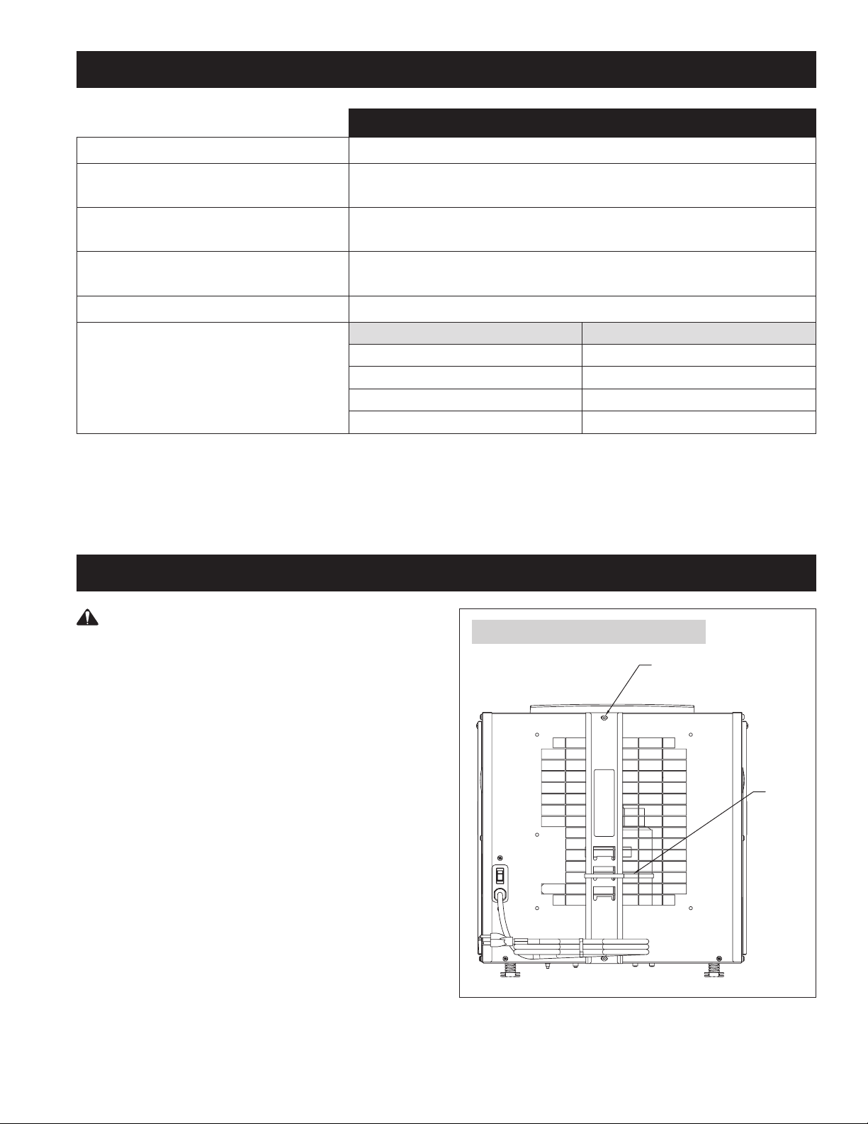
IMPORTANT: Cut the strap securing the compressor
shipping support bracket and remove the strap and shipping bracket.
See Figure 1.
FIGURE 1 – Remove Shipping Bracket
REMOVE SCREWS (2)
DISCARD SHIPPING BRACKET
REINSTALL SCREWS (2)
CLIP OFF
PLASTIC
STRAP
90-2013
3
SET UP DEHUMIDIFIER FOR INSTALLATION (CONTINUED)
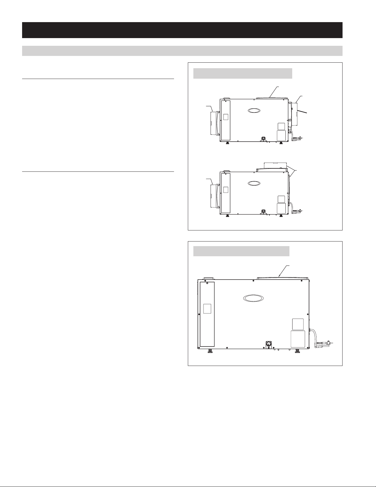
DUCT COLLARS
STANDARD BASEMENT AND ATTIC INSTALLATIONS
(FULLY DUCTED)
FIGURE 2 – Fully Ducted Installations
• Use the screws in the parts bag to attach the duct collars to
the inlet and outlet of the dehumidifier. The outlet collar has a
backflow damper.
• The outlet duct collar may be attached to the top or end of the
unit. Move the outlet cover to the location not being used. See
Figure 2.
• Make sure there are no bends in the ductwork coming off the
outlet for a minimum of 4”. This will ensure that the ductwork will
not interfere with the backflow damper function.
SEALED ATTIC OR BASEMENT INSTALLATIONS
If dehumidifying the space in which the dehumidifier is installed, the
duct collars do not need to be installed. Leave the outlet cover on
top of the unit. See Figure 3.
INLET
DUCT
COLLAR
END DISCHARGE
INLET
DUCT
COLLAR
TOP DISCHARGE
FIGURE 3 – Non-ducted Installations
OUTLET COVER
OUTLET DUCT
COLLAR W/BACK
DRAFT DAMPER
MOVE OUTLET
COVER AND
INSTALL DUCT
COLLAR TO
TOP DISCHARGE
LOCATION
90-2014
OUTLET COVER
90-2016
4
SET UP DEHUMIDIFIER FOR INSTALLATION (CONTINUED)
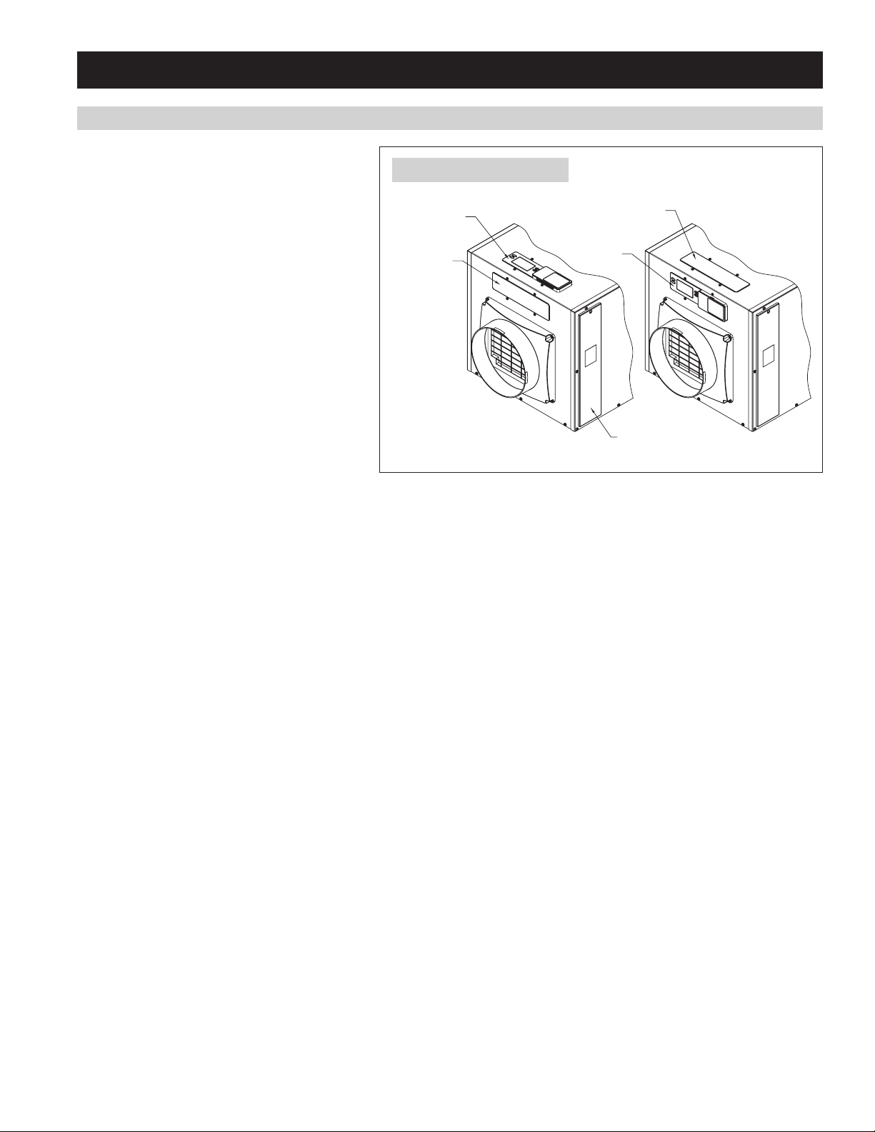
CONTROL LOCATION
The on-board control can be located on the top of the
dehumidifier or can be relocated to the front of the
dehumidifier if the control can not be seen/accessed in
the top orientation.
To move the control:
1. Remove the front control panel cover.
2. Remove the filter access door and filter.
3. Detach the on-board control by removing the four
(4) screws around the control. NOTE: Use one hand
to support the bottom of the on-board control when
removing.
4. Keep the control in the unit and relocate to the front
access hole.
FIGURE 4 – Control Location
CONTROL
CONTROL
PANEL COVER
CONTROL
PANEL COVER
CONTROL
5. Secure the control with the same four screws used
to attach the control to the top of the unit.
6. Secure the control panel cover to the top of the unit.
FILTER ACCESS DOOR
90-2017
5
1870W HARD WIRING
WARNING
ELECTRICAL SHOCK HAZARD: 115-volts may cause serious injury or death from
electrical shock. Disconnect and tag electrical service before starting installation or
field-service. Leave electrical service disconnected until installation or field-service
is complete.
ELECTRICAL SHOCK HAZARD: An interrupted or broken ground may cause property
damage, serious injury or death should an electrical fault occur. The cabinet must
be grounded in accordance with NEC ANSI/NFPA 70-2011 or local codes. In Canada,
refer to Canadian Electrical Code CSA C22.1.
FIRE HAZARD: Use of improper wire may cause serious injury, property damage or
death due to fire. Do not use aluminum wire for electrical service to the dehumidifier.
Use only copper wire.
The Model 1870W dehumidifier must be hard wired. An electrical disconnect switch can be installed as needed to comply with appropriate
codes or ordinances. The ON/OFF switch on the dehumidifier interrupts the 115VAC service to the internal components of the dehumidifier, but
does not disconnect the power supply at the 115VAC terminals on the dehumidifier.
United States Installations: Make all electrical connections in accordance with the current edition of the NEC ANSI/NFPA 70 and any local
codes or ordinances that may apply.
Canada Installations: Make all electrical connections in accordance with the current edition of the Canadian Electrical Code CSA C22.1 and
any local codes or ordinances that may apply.
Use of an undersized circuit
breaker may cause property
damage and/or the need for
mold remediation service. See
Specifications for wire and
circuit breaker sizing.
CAUTION
ELECTRICAL SPECIFICATIONS FOR HARD WIRING MODEL 1870W
Voltage
Minimum Circuit Capacity
Maximum Fuse or Circuit Breaker Amps
Minimum Wire Size AWG
Model 1870W
110-120 VAC, 60 Hz, 1 phase
12A
20A
14
6
1870W HARD WIRING (CONTINUED)
WIRING INSTRUCTIONS
1. Disconnect electrical service at the main fuse or circuit breaker box.
2. Install any code required electrical disconnects to the line service.
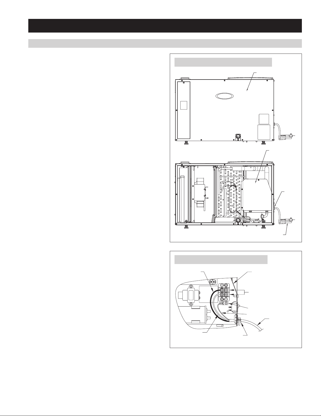
3. Remove the side panel and electrical service panel from the
dehumidifier. See Figure 5.
4. Route the service cable through the 7/8” diameter hole where the
power cord was removed. USE ONLY COPPER SUPPLY WIRES.
5. Secure the cable/conduit to the dehumidifier using fittings/
connectors approved for the type of cable/conduit used.
6. Connect the ground wire of the service cable to the ground lug in
the electrical service box. See Figure 6.
7. Connect the line voltage wires of the service cable to the LINE
BLK and NTRL WHT terminals. See Figure 6.
8. Reattach the electrical service panel and side panel.
9. Restore electrical service at the main fuse or circuit breaker box.
FIGURE 5 – Electrical Service Box Location
SIDE PANEL
ELECTRICAL
SERVICE BOX
90-2018
FIGURE 6 – Hard Wire to 115 VAC Service
LINE
VOLTAGE
USE COPPER
SUPPLY WIRES
LINE
90-2019
NEUTRAL
UTILISER DES FILS
D'ALIMENTATION
EN CUIVRE.
BLK
NTRL
WHT
G
FITTING AS
REQUIRED
115V AC WIRING
TERMINALS
GROUND LUG
GROUND
STRAIN
RELIEF
POWER CORD
ELECTRICAL
SERVICE BOX
LINE SERVICE
CABLE/CONDUIT
7
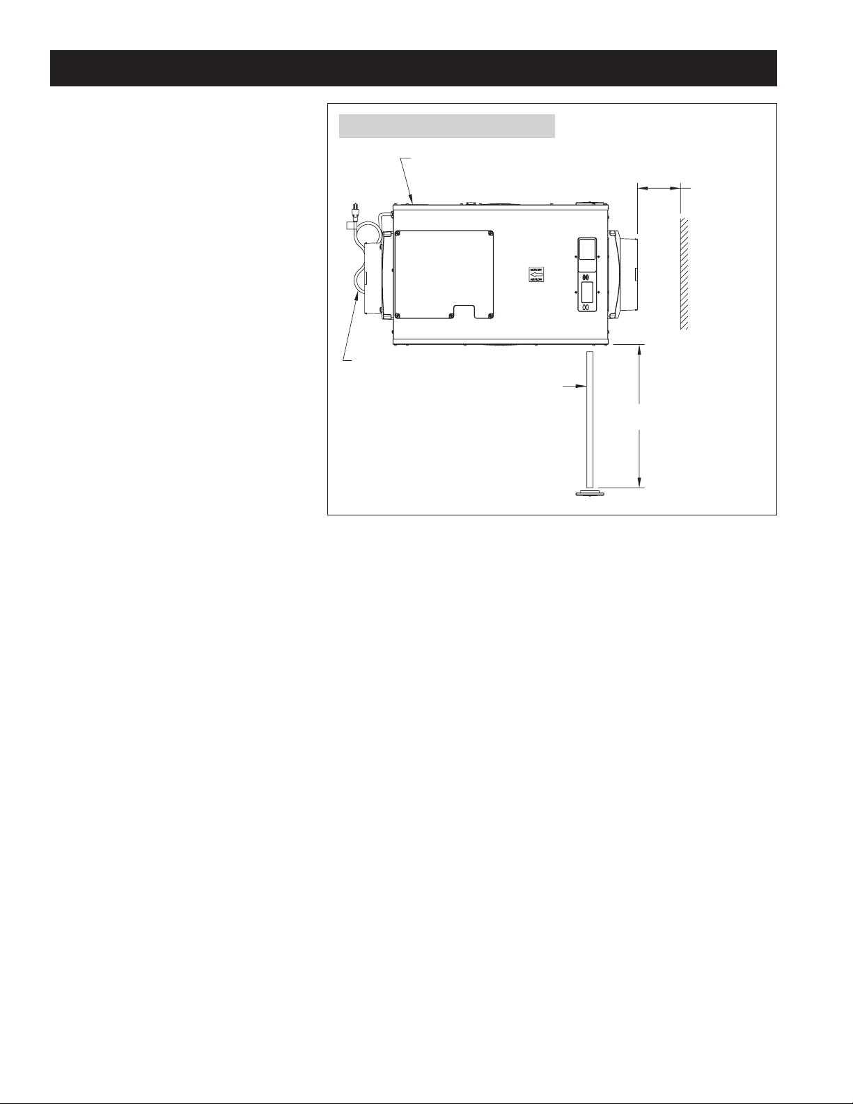
LOCATION CONSIDERATIONS
• Allow sufficient clearance for filter removal and
to prevent airflow obstruction
FIGURE 7 – Filter Access Clearance
• Electrical service access will require the removal
of the side panel shown. Allow sufficient space
for service on this side of the unit.
• If locating the unit in an attic or crawl space, a
Model 76 Control mounted in the living space is
recommended.
• For attic installations, it is recommended that
the dehumidifier be suspended.
• Always install the dehumidifier in a condensate
pan when locating in or over a finished space.
ELECTRICAL SERVICE
ACCESS THIS SIDE
6 FT. POWER CORD
TOP VIEW
FILTER
MINIMUM
20"
CLEARANCE
FOR FILTER
(EITHER SIDE)
6" MINIMUM
CLEARANCE
FOR PROPER
AIR FLOW
90-2020
8

DRAIN INSTALLATION
The drain outlet on the dehumidifier can be hard piped using a 3/4” PVC Slip x 3/4” MNPT fitting and 3/4” nominal drain tubing or the provided
3/4” MNPT x 3/4” hose barb fitting and 3/4” clear PVC tubing can be used to drain the dehumidifier. Always maintain a constant downward
slope from the dehumidifier to the drain and do not allow soft tubing to curl up which may result in air lock. NOTE: PTFE thread seal tape is
recommended for the threaded connection and hand tighten only. If hard pipe is used, PVC primer and cement is recommended for the slip fit
connection.
LEVELING
The feet can be adjusted to level the unit, and
if required, to accommodate drain fittings and a
secondary condensate pan. Leveling is required
to ensure proper drainage from the dehumidifier.
See Figure 8.
FIGURE 8 – Level the Unit
0.38” MIN
2.00” MAX
CONDENSATE PAN, CONDENSATE PUMP AND FLOAT SWITCH
Always install the dehumidifier in a condensate pan
when locating in or above a finished space. Adhere
FIGURE 9 – Float Switch Wiring
to local codes regarding draining of the condensate
pan. If a condensate pump is needed, install it in the
condensate pan as well.
Install a condensate overflow safety switch (i.e. float
switch) in the condensate pan, remove the factory
installed jumper wire between the Float Switch
terminals on the control and wire the float switch
to the dehumidifier as shown in Figure 9. Overflow
safety switches on condensate pumps can be wired
to the Float Switch terminals in a similar fashion.
3/4” FNPT DRAIN
DH DH
FLOAT
Switch
NORMALLY CLOSED
FLOAT SWITCH
90-2021
90-1857
9
 Loading...