

Aprilaire 1820 Installation Manual
Model 1820 Dehumidifier
Installation Instructions
SAFETY INSTRUCTIONS
WARNING
1. 120 Volts may cause serious injury from electric shock. Disconnect electrical power before starting installation or servicing.
Leave power disconnected until installation/service is completed.
2. Sharp edges may cause serious injury from cuts. Use care when cutting plenum openings and handling duct work.
3. Dropping may cause personal injury or equipment damage. Handle with care and follow installation instructions.
CAUTION
1. Read all instructions before beginning installation.
2. Improper installation may cause property damage or injury. Installation, service, and maintenance must be performed by a
qualified service technician.
3. Do not use in pool applications. Pool chemicals can damage the dehumidifier.
4. Do not use solvents or cleaners on or near the circuit board. Chemicals can damage circuit board components.
5. Wait 24 hours before running the unit if it was not shipped or stored in the upright position
TABLE OF CONTENTS
Safety Instructions........................................1
Specifications............................................2
Set Up Dehumidifier for Installation ........................2
Packaging Content .......................................2
Duct Collars ............................................2
Location Considerations...................................3
Installation...............................................3
Leveling ...............................................3
Ductwork Installation.....................................3
Drain Tubing and Condensate Pump Installation ...............4
Model 76 – Crawl Space Control and Wiring ................5
READ AND SAVE THESE INSTRUCTIONS
Air Cycling...............................................5
System Set-Up, Check & Start-Up ..........................6
Remote Control – Crawl Space.............................6
Ventilation / Air Cycling...................................7
System Check...........................................7
Crawl Space Using the Dehumidifier Control..................8
Crawl Space Remote Control Using Model 76 .................8
Start-Up ...............................................8
Troubleshooting ..........................................9
Table 1 – Diagnostic Codes................................9
Table 2 – Troubleshooting Guide...........................10
Service Parts............................................11
1
CLIP OFF
REMOVE SHIPPING BRACKET
SPECIFICATIONS
OUTLET
COLLAR
INLET
DUCT
COLLAR
Model 1820
Weight
56 lbs.
Capacity: AHAM DH-1-2008 80°F, 60% RH Conditions 70 pints per day @ 200 CFM
Power: 115 VAC, Single Phase, 60Hz 5.8 Amps operating current
Dehumidifier Inlet Air Conditions
Filter
Airflow
Dehumidification: 50°F – 104°F, 40°F dew point minimum
Ventilation: 40°F – 140°F, 0%RH – 99%RH (non-condensing)
MERV 8, washable
200 CFM
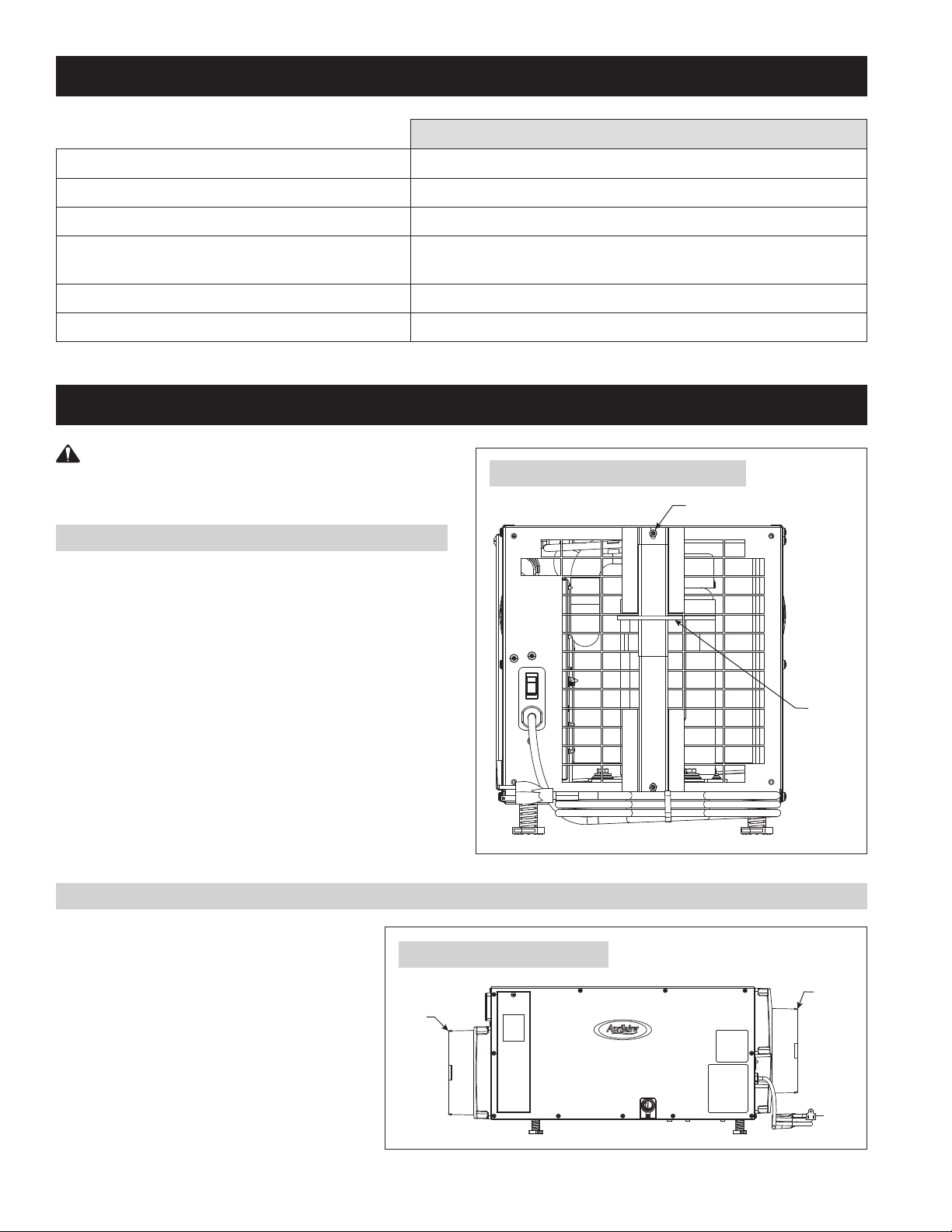
SET UP DEHUMIDIFIER FOR INSTALLATION
IMPORTANT: Cut the strap securing the compressor
shipping support bracket and remove the strap and shipping bracket.
See Figure 1.
PACKAGING CONTENT
1. Dehumidifier
2. Inlet/Outlet Collars
FIGURE 1 – Remove Shipping Bracket
3. Literature
a. Installation Instructions
b. Owner’s Manual
4. Parts Bag
a. #10 x 1/2 Screws (9)
b. Threaded Barbed Fitting for Drain
Connections
c. Torx Bit
5. 10 foot, 3/4” Drain Tube
DUCT COLLARS
Use the screws in the parts bag to attach the duct
collars to the inlet and outlet of the dehumidifier.
See Figure 2.
PLASTIC
STRAP
90-2302
FIGURE 2 – Install Duct Collars
DUCT
2
90-2308
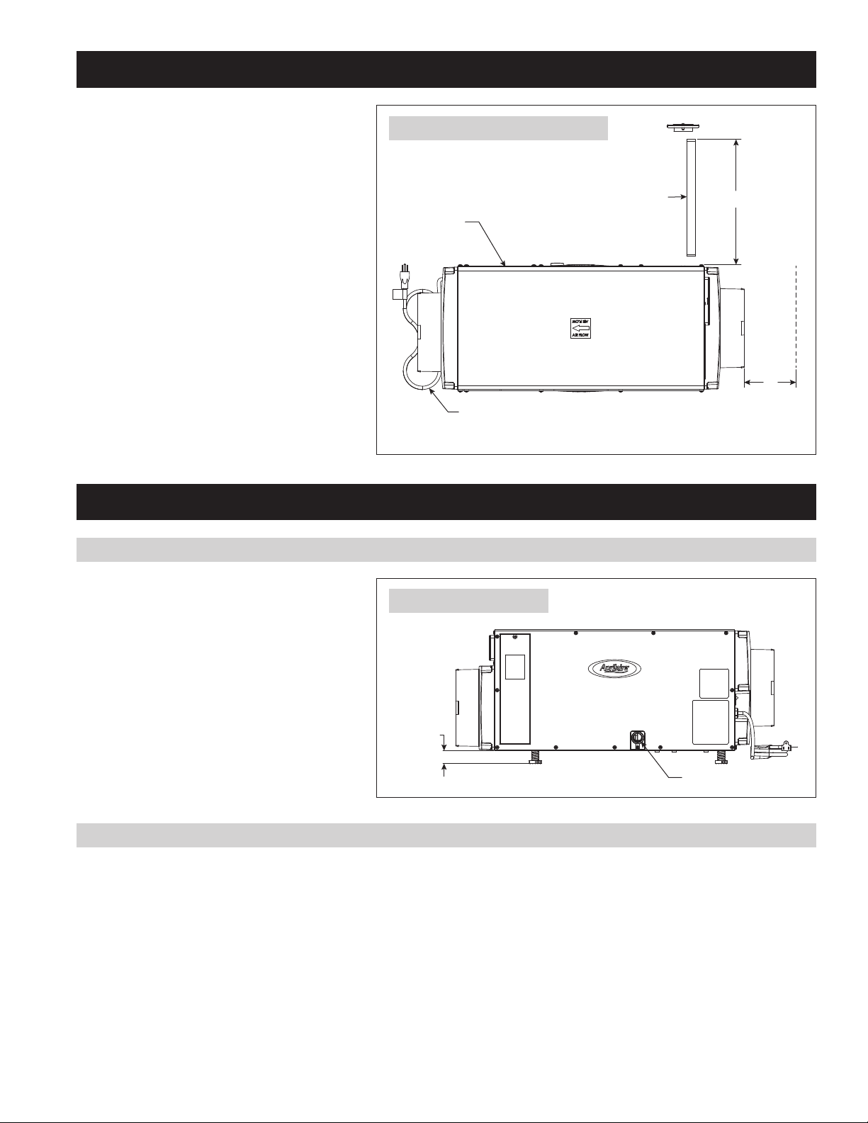
LOCATION CONSIDERATIONS
FOR PROPER
AIR FLOW
2.00" MAX
3/4" FNPT DRAIN
• Allow sufficient clearance for filter removal and
to prevent airflow obstruction
• Electrical service access will require the removal
of the side panel shown. Allow sufficient space
for service on this side of the unit.
FIGURE 3 – Filter Access Clearance
ELECTRICAL
SERVICE ACCESS
THIS SIDE
8 FT. POWER CORD
90-2304
TOP VIEW
FILTER
MINIMUM
13"
CLEARANCE
FOR FILTER
MINIMUM
CLEARANCE
6"
INSTALLATION
LEVELING
The feet can be adjusted to level the unit, and
if required, to accommodate drain fittings and a
secondary condensate pan. Leveling is required
to ensure proper drainage from the dehumidifier.
See Figure 4.
DUCTWORK INSTALLATION
Adding 5-10 feet of insulated ductwork to the inlet and outlet of the dehumidifier will ensure dehumidified air is circulated throughout the crawl
space and will reduce the noise level of the dehumidifier. Point the inlet and outlet ducts in opposite directions to minimize recirculation of
dehumidified air.
FIGURE 4 – Level the Unit
0.38" MIN
90-2305
• Maximum recommended total duct length is 100 feet.
• To avoid pulling in dirt and other particles, do not lay intake duct on the floor of the crawl space.
NOTE: This dehumidifier is designed for crawl space and stand-alone applications only. Do not duct to HVAC system.
3
INSTALLATION (CONTINUED)
3/4" CLEAR PVC TUBING
(INCLUDED)
CONDENSATE PUMP
FLOAT SWITCH
WIRE
3/4" MNPT x 3/4"
BARB FITTING
(INCLUDED)
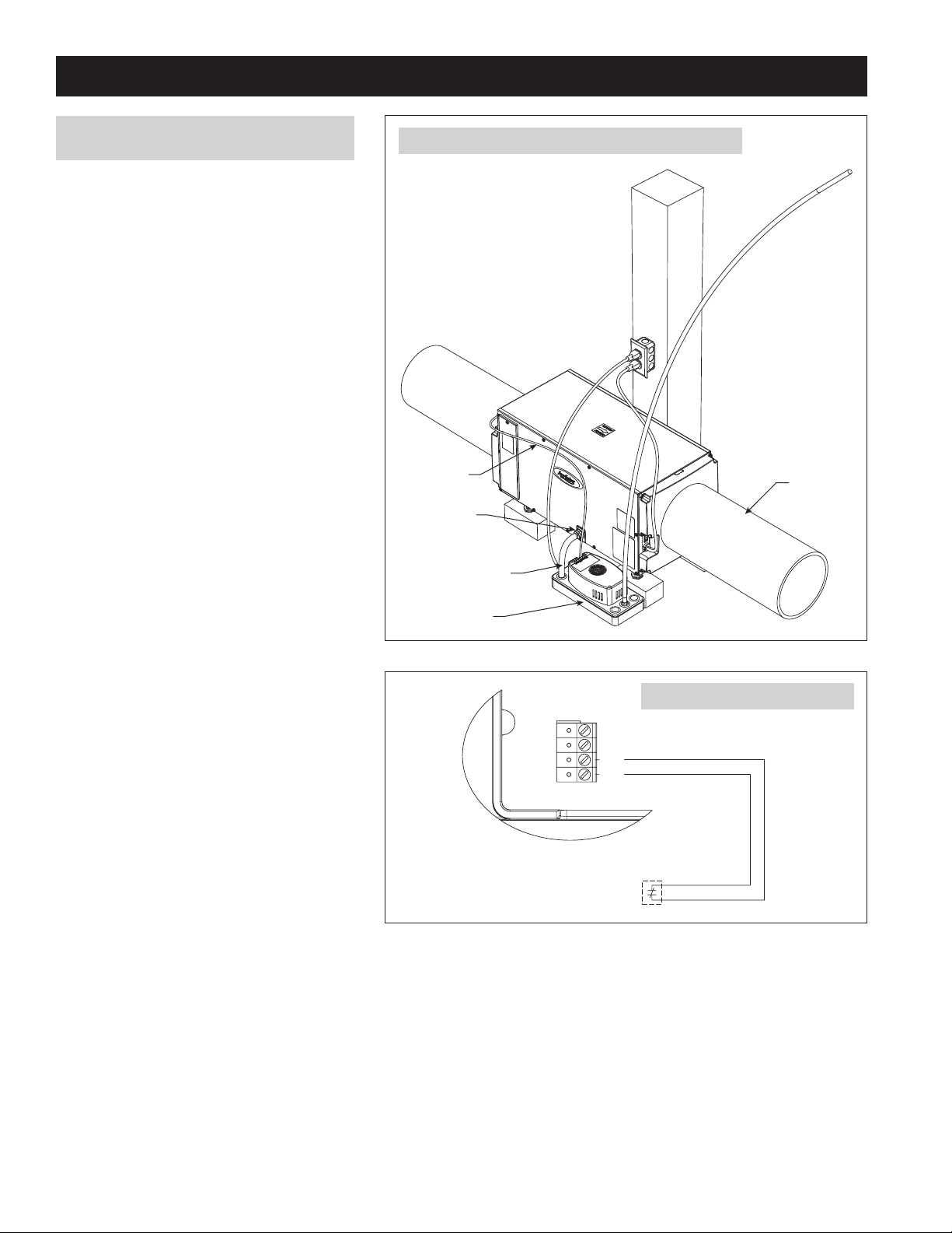
DRAIN TUBING AND CONDENSATE PUMP
INSTALLATION
The drain outlet on the dehumidifier can be plumbed
directly to a condensate pump (see Figure 5) using
the provided 3/4” MNPT x 3/4” hose barb fitting
and 3/4” clear PVC tubing. Always maintain a
constant downward slope from the dehumidifier to
the condensate pump. NOTE: PTFE thread seal tape
is recommended for the threaded connection. Hand
tighten only. The 4856 condensate pump is capable
of lifting water up to 22 feet. The dehumidifier can
be elevated (while remaining level) to increase
downward slope for proper draining. Wire the float
switch terminals to the normally closed contacts on
the condensate pump (see Figure 6).
FIGURE 5 – Drain and Condensate Pump Installation
8" DIAMETER
INSULATED
FLEX DUCT
FIGURE 6 – Float Switch Wiring
DH DH
FLOAT
Switch
LOW VOLTAGE NORMALLY CLOSED
CONTACTS ON CONDENSATE PUMP
90-2306
90-1857
4
 Loading...