

Aprilaire 1510 User Manual
Model 1510 Media Air Cleaner
E
Installation Instructions
WARNING
1. High voltage may cause serious
injury from electrical shock.
Disconnect power to the
furnace/air handler before
starting installation.
2. Sharp edges may cause injury
from cuts. Use care when cutting
and handling sheet metal.
SPECIFICATIONS
Model 1510
Airflow Capacity
Replacement Media
Max. Equipment Weight
Air Cleaner Operating Environment
up to 3000 CFM maximum
Model 510 or 513 with SelfSeal
Cabinet will support 400 lb. static load
Temperature: 0°F
CAUTION
1. To prevent component failure, do not install the air cleaner on the warm
air supply or in an area where the temperature may exceed 140°F. This
may include areas above heat exchangers in downflow furnaces or above
exhaust flues in lowboy furnace cold air returns.
2. Installation must be done by a qualified heating and air conditioning
professional. Read instructions thoroughly before beginning installation.
3. Do not install air cleaner downstream of a UV light. UV lamps will cause
degradation of the filtering media.
™
–
140°F. Humidity: 0–90% non-condensing.
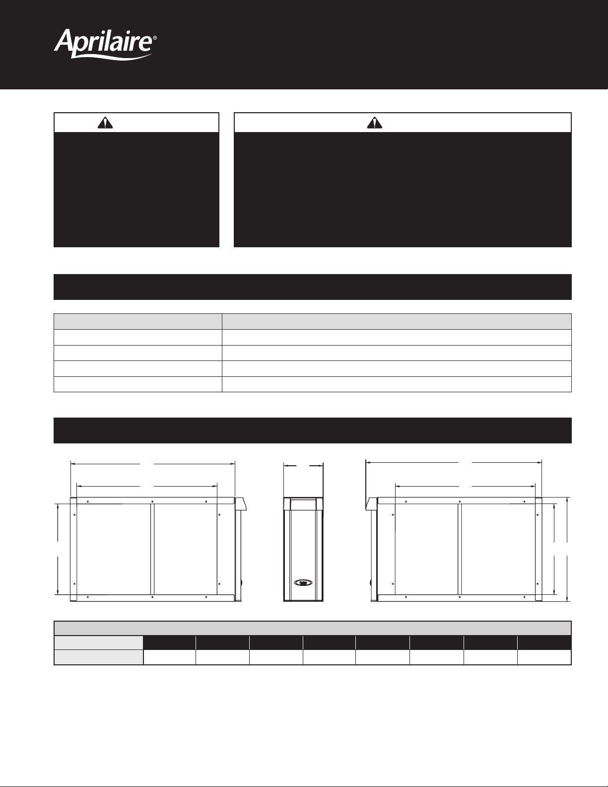
DIMENSIONS
A
Model A B C D E F G H
1510
B
without door
C
28-3/4 28-1/16 23-7/8 6-3/4 30-1/16 23-7/8 28-3/4 31
D
TABLE 1 – Dimensions (inches)
with door
F
G H
90-1333
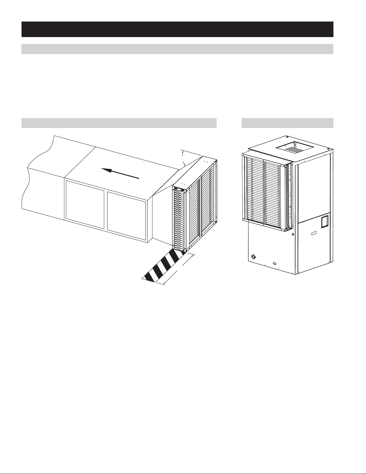
INSTALL THE AIR CLEANER CABINET
LOCATING THE AIR CLEANER
1. Leave sufficient space in front of the air cleaner for the removal of the filtering media (see Figure 1).
2. DO NOT INSTALL DOWNSTREAM OF A UV LIGHT. UV lamps will cause degradation of the filtering media.
3. Figure 1 shows typical application of the air cleaner mounted to a horizontal system.
4. Figure 2 shows the air cleaner mounted to the side of a geothermal heat pump.
FIGURE 1 FIGURE 2
45° MAX
AIR FLOW
29"
10-10998 90-1769
2
 Loading...