

Humidifier
Steam Humidifier
Models 1150, 1160, and 1180
Installation, Operation, and Maintenance Manual
READ AND SAVE THESE INSTRUCTIONS

TABLE OF CONTENTS
PRODUCT OVERVIEW . . . . . . . . . . . . . . . . . . . . . . . . . . . . . . 3
Materials Provided and Not Provided . . . . . . . . . . . . . . . . . .
Electrical Specifications, Capacities and Weights . . . . . . . .
Dimensions. . . . . . . . . . . . . . . . . . . . . . . . . . . . . . . . . . . . . . . 5
Overview of Humidifier Operation
Sequence of Operations
INSTALLATION
Wiring Diagrams, Unit
Setting Slide Switches
Choosing a Location for Humidifier Components . . . . . . . . 17
Distribution Tube Installation . . . . . . . . . . . . . . . . . . . . . . .
Mounting the Humidifier . . . . . . . . . . . . . . . . . . . . . . . . . . .
Field Wiring . . . . . . . . . . . . . . . . . . . . . . . . . . . . . . . . . . . . .
Wiring Diagrams, Input . . . . . . . . . . . . . . . . . . . . . . . . . . . .
Airflow Proving Switch Installation
Supply Water and Drain Piping
. . . . . . . . . . . . . . . . . . . . . . . . . . . . . 8
. . . . . . . . . . . . . . . . . . . . . . . . . . . . . 12
. . . . . . . . . . . . . . . . . . . . . . . . . . . . . 15
. . . . . . . . . . . . . . . . . . . . . 7
22
24
25
27
. . . . . . . . . . . . . . . . . . . 29
. . . . . . . . . . . . . . . . . . . . . . 29
ATTENTION INSTALLER
OPERATION
3
4
Start-up Proced
MAINTENANCE
Inspect and Service the Humidifier
Off-season Shut Down Procedure
TROUBLESHOOTING . . . . . . . . . . . . . . . . . . . . . . . . . . . . . . 39
REPLACEMENT PARTS . . . . . . . . . . . . . . . . . . . . . . . . . . . .
APPENDIX – ABSORPTION
DISTANCE CALCULATION
WARRANTY . . . . . . . . . . . . . . . . . . . . . . . . . . . . . . . Back Cover
ure . . . . . . . . . . . . . . . . . . . . . . . . . . . . . . . . 33
. . . . . . . . . . . . . . . . . . . 35
. . . . . . . . . . . . . . . . . . . . 38
. . . . . . . . . . . . . . . . . . . . . . . . . . 46
WARNING
1. 240 volts may cause serious injury or death from electrical
shock. Disconnect power before installing supply wiring.
43
This product must be installed by qualified HVAC and
electrical contractors. Failure to do so voids product
warranty due to possible product misapplication.
This product must be installed in compliance with
local, state, and federal codes.
CAUTION
1. Do not set humidity higher than recommended.
Condensation damage may result.
2. Failure to follow the instructions in this manual
for installation of distribution tube, airflow
proving switch, and high humidity limit switch
may cause condensation damage.
2. Water temperature in excess of 140°F (60°C) may cause
serious injury due to burns. Allow unit to cool before
draining or removing chamber.
3. The humidifier chamber, distribution assembly, and all
connected hose or piping may contain or discharge hot
steam and/or hot water at 212°F (100°C). Discharged
steam is not visible. Contact with hot surfaces,
discharged hot water, or air into which steam has been
discharged may cause severe personal injury.
4. Water pressure greater than 120 psi (827 kPa) may
cause the humidifier to overflow.
5. Humidifier weighs up to 100 lbs (45 kg) when operating.
Improper mounting of humidifier may cause humidifier
to fall from wall or ceiling resulting in serious injury.
Mount humidifier to a structurally stable surface per the
instructions in this manual.
6. Failure to properly ground unit may result in property
damage due to fire, or serious injury or death from
electrical shock.
7. Failure to follow the instructions in this manual may
cause moisture to accumulate, which may cause
bacteria and mold growth or dripping water into building
spaces. Dripping water may cause property damage.
2

PRODUCT OVERVIEW
Aprilaire Steam Humidifiers create steam by boiling water inside a steam chamber. This is accomplished by the transfer of energy
from electric heating elements to the water inside the chamber. A three-level water probe is used to determine when to turn on
and off a water fill valve in order to bring water into the chamber. Once the chamber is full and there is a call for humidity from
the Automatic Steam Humidifier Control, the heating elements will be energized causing the water to boil. The boiling water
creates steam which, due to the moderate pressurization of the chamber that comes from boiling, is forced through the vapor
hose and steam distribution tube into the duct system. As water is boiled off, the water level in the steam chamber will drop. The
water probe will sense when it reaches a low point and will cause the fill valve to open.
The process of boiling the water in the steam chamber will cause minerals and impurities in the water to drop out. Depending
on the hardness and quality of the water, this can create a substantial build-up within the steam chamber. The unit will drain the
chamber periodically to help clean the steam chamber and reduce the amount of cleaning required during maintenance.
Aprilaire Steam Humidifiers are controlled by an Automatic Steam Humidifier Control mounted in the return duct that will sense
the relative humidity (RH) in the return air. If the return air is below the RH setpoint, the control will send the humidifier a signal
to begin producing steam. Once this happens, the airflow proving switch (included) will check to ensure that the equipment
blower is operating. If the blower is not operating, the humidifier can send the equipment a signal to turn the fan on.
• The Aprilaire Steam Humidifier Model 1150, 12 lb/hr unit, features an Automatic Steam Humidifier Control with on/off control.
The on/off control will send a 10 VDC signal to the humidifier when the measured return air RH is 3% or more below setpoint
to turn the unit on at 100% output.
• The Aprilaire Steam Humidifier Model 1160, 24 lb/hr unit, and the Model 1180, 48 lb/hr unit, feature an Automatic Steam
Humidifier Control with modulating control. This control sends a signal between 0 and 10 VDC that is proportional to the
difference between setpoint RH and the measured return air RH. The signal for 100% humidifier output is 10 VDC and occurs
at a control point that is adjustable. The signal for 50% output is 5 VDC and occurs at the setpoint. The adjustable RH
proportional control band can be set on the board to 6%, 9%, 12% (default), or 15%. The humidifier uses this varying signal to
time-proportion the operation of the heating elements in the chamber.
The Automatic Steam Humidifier Control features an outdoor temperature sensor and is equipped to provide RH setpoint
compensation based on the actual outdoor temperature. When the weather gets colder outside, there can be problems with
condensation when introducing humidity into the building. The control recognizes this and adjusts the setpoint in the building to
a lower level. The control will still provide humidity to the building, but will not attempt to maintain a humidity level higher than
is appropriate for the current outdoor temperature. For applications that require specific set-point control, regardless of outdoor
temperature, the Control can be set up for manual operation. In Manual Mode, the outdoor temperature sensor is not used and
the RH is controlled to the specific setting on the Control.
MATERIALS PROVIDED MATERIALS NOT PROVIDED
1 Humidifier (Model 1150: 1 heater, 12 lbs/hr; Model 1160: 2 heater, 24 lbs/hr; Model 1180:
3 heater, 48 lbs/hr)
1 Distribution Tube (Model 1150: 10” active, 14” overall; Model 1160: 16” active, 20” overall;
Model 1180: 25½” active, 29½” overall.
1 10 ft. Steam Hose, 1½” I.D. for Models 1150/1160, 2" I.D. for Model 1180
1 1 ft. Drain Hose, 1” I.D.
2 Hose Clamps (for Steam Hose)
2 Hose Clamps (for Drain Hose), 1” I.D.
2 Face Plates for Mounting Distribution Tube (1 set)
2 3/8” x 2” Lag Bolts for Mounting Humidifier
1 Automatic Steam Humidifier Control
1 Airflow Proving Switch
1 Installation, Operation, and Maintenance Manual
Electrical Supplies – quick disconnect box,
conduit, and wire (for power to the unit
and wiring to control devices)
Plumbing Supplies – supply and drain
piping, fittings, etc.
High Humidity Limit Switch
Hanging Brackets – for mounting
humidifier from ceiling
Plastic Tubing, ¼" I.D. – for airflow proving
switch
Sheet Metal Screws – for attaching
distribution tube faceplate
3
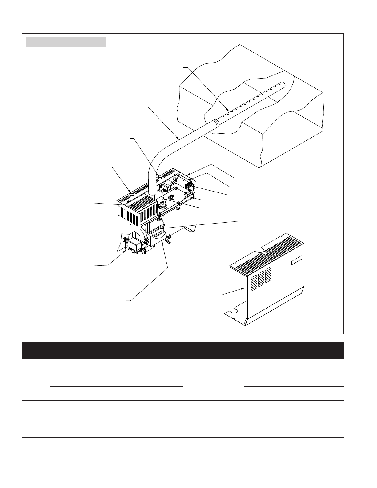
FIGURE 1 – Product Overview
Distribution Tube
Flexible steam hose (1½" in Models 1150 and 1160,
2" in Model 1180)
Control wiring knockout
Power wiring knockout
Electrical power area
¾” (DN20) copper
overflow and drain
Duct
Electrical controls area
Internal controller board
Field wiring terminal block
Display panel
Fill Valve ¼” (DN8) compression fitting
Immersion heaters
(1 in Model 1150, 2 in Model 1160, and
3 in Model 1180)
Removable steam chamber
Cover/shroud
TABLE 1 – Electrical Specifications
Current draw (amps)
Single-phase Three-phase
Circuit
Breaker
(amps)
kW
Model
number
Maximum
steam capacity
minimum
lbs/hr kg/h 240V* 240V* lbs kg lbs kg
1150 12 5.4 16.7 -- 25 4 62 28 59 27
1160 24 10.9 33.3 -- 45 8 62 28 68 31
1180 48 21.8 -- 38.5 50 16 88 40 101 46
Note: Models 1150,1160 and 1180 operate at 50/60 Hz.
* 208V single-phase may also be used but the steam capacity will be approximately 25% lower than the values above. It is recommended that the same size
circuit breakers be used with 208V single-phase as listed above for 240V.
4
Shipping weight
(includes packaging
and all materials in
the box)
Operating weight
(humidifier only, with
water in chamber)
OM-4051
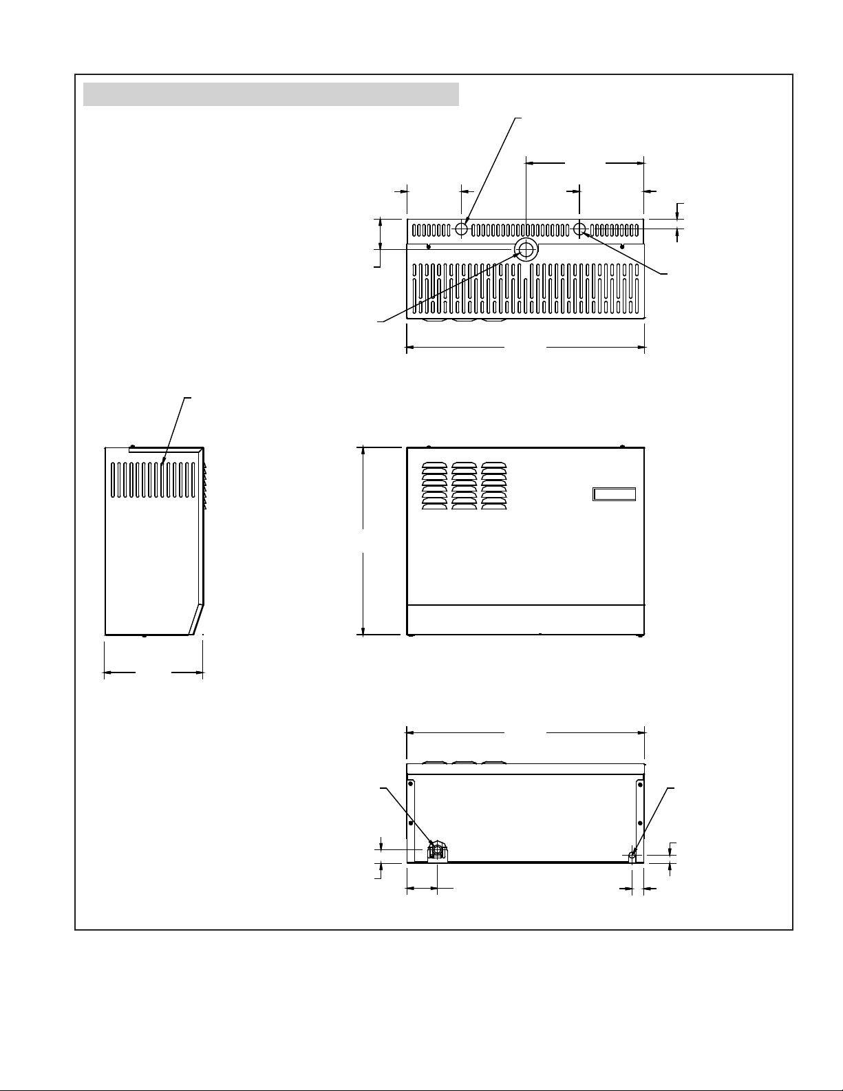
FIGURE 2 – Dimensions (pertains to Models 1150, 1160 and 1180)
Power wire knockout
LEFT SIDE
VIEW
Venting
3.09”
(78 mm)
Steam outlet
18.93”
(481 mm)
TOP VIEW
5.50”
(140 mm)
24.06”
(611 mm)
FRONT VIEW
11.89”
(302 mm)
(165 mm)
6.50”
1.00” (25 mm)
Control wire knockout
9.99”
(254 mm)
Models 1150/1160
15.6”
(396 mm)
Model 1180
Chamber drain
1.37” (35 mm)
BOTTOM VIEW
(611 mm)
3.06” (78 mm)
24.06”
Chamber fill
0.83” (21 mm)
1.19” (30 mm)
OM-4039
5
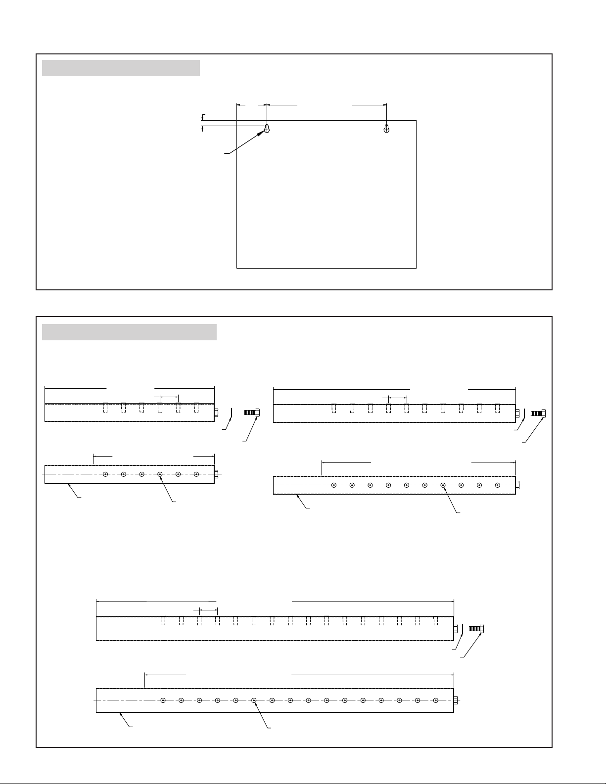
FIGURE 3 – Mounting Hole Locations
BACKVIEW
Keyhole for 3/8" diameter fasteners (2)
FIGURE 4 – Distribution Tube Dimensions
MODEL 1150
14" Tube length
1.50 (TYP)
0.75"
(19.0mm)
16.00" (406.4mm)4.00"
90-914
MODEL 1160
20" Tube length
1.50 (TYP)
10" Active dispersion length
1½" Diameter
dispersion tube
MODEL 1180
3/8" Flat washer
3/8-16 x ½" Hex head bolt
Molded tubelet with
3/16" orifice
1.50 (TYP)
25½" Active dispersion length
29½" Tube length
1½" Diameter
dispersion tube
3/8" Flat washer
3/8-16 x ½" Hex head bolt
16" Active dispersion length
Molded tubelet
with ¼" orifice
3/8" Flat washer
3/8-16 x ½" Hex head bolt
2" Diameter dispersion tube
Molded tubelet with ¼" orifice
90-912
6
OVERVIEW OF HUMIDIFIER OPERATION
INTERNAL CONTROLLER - FEATURES OF OPERATIONS
The internal controller within the humidifier cabinet responds to external inputs (e.g., humidistat and airflow proving switch) and
internal inputs (e.g., water level probe inside the steam chamber) to provide:
• Relative humidity (RH) control
– Model 1150: With an on-off demand signal, the controller
maintains RH within 5% to 7% of set point.
– Model 1160 and 1180: With a modulating demand signal,
the humidifier maintains RH within 2% to 4% of set
point. Modulating demand signal options include a 0–10
VDC humidistat signal (humidistat provided), or a signal
by others (0–10 VDC or 4–20 mA).
• Automatic water level control and safety shut-down
If there is insufficient water, an electronic water level
probe sends a signal to the controller to add water or to
turn off the heaters. (See Figure 5
• Operating time monitoring
.)
The controller accumulates humidifier run time to activate
end-of-season draining, water cool-down, and auto draining.
• Automatic preheating
– Model 1160 and 1180: During normal operation, in the
case of a re-fill cycle or a period of no demand for
humidity, the controller will recognize that the tank has
cooled down. The heaters will energize for an
appropriate amount of time to bring water close to
boiling temperature. Preheat only occurs when there is
a demand for humidity.
• Chamber water cooling before draining
To ensure that water is at or below 140°F (60°C) before
discharging to the plumbing system, the humidifier remains
idle for a defined period of time before draining.
• Ensuring duct airflow
The humidifier will not make steam unless the HVAC
system blower is on and the airflow proving switch verifies
there is airflow in the duct.
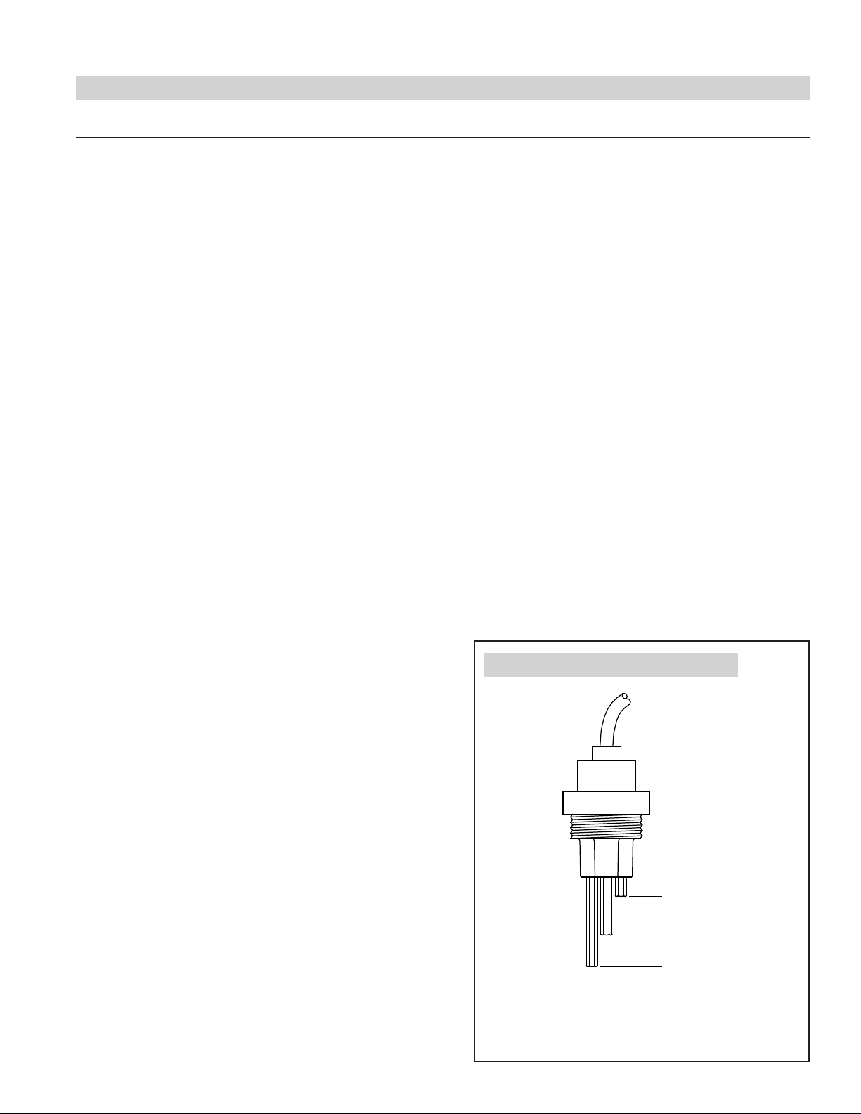
FIGURE 5 – Electronic Water Level Probe
• Automatic end-of-season draining
If the humidifier doesn’t receive a humidity demand signal
for 72 hours, the chamber automatically drains.
• Periodic drain and flush
To reduce mineral buildup in the chamber, the humidifier
automatically drains at intervals based on operating time,
output capacity, and water type. At the end of the drain
cycle, the supply water is brought on to briefly flush the
chamber.
Fill valve closes
Fill valve opens
Low-water cutoff
The humidifier monitors and controls water levels electronically
using a three-rod probe. The humidifier responds with the above
actions when the water level reaches each probe rod.
VLC-OM-030
7

SEQUENCE OF OPERATIONS
Note: Sequence is for normal operation, starting with an empty Steam Chamber.
Model 1150 Humidifier is connected to: 240 VAC, single phase input power; Model 57 on/off Automatic Steam Humidifier
Control (ASHC); Airflow Proving Switch and High Humidity Limit Switch. Water supply is turned on, steam distribution and drain
connections are made.
TABLE 2 – Sequence of operation for Model 1150
Operation Expected Results
Humidifier power turned on.
Fill Sequence:
Water level probe will sense an empty chamber and turn on
the fill valve.
Demand for humidity from control circuit:
(ASHC is calling for humidity and airflow is present.)
As water is boiled off, the water level drops and the water
level probe will sense a need for more water in the chamber.
Demand for humidity is satisfied.
After a predetermined amount of run time (element energized),
an Autodrain sequence is performed. The control will initiate
Autodrain during a period of inactivity when the water in the
chamber is cool.
If demand for humidity prevents the chamber from cooling,
a forced Autodrain sequence is initiated. During a forced
Autodrain sequence, the humidifier will not generate steam,
even if there is a call for humidity.
End of season drain.
• Internal Controller (LW420) powered up.
• LEDs blink - On/Off LED stays on.
• +24 VDC available at terminal #30 on humidifier referenced to C.
• After a few second delay, the Fill LED will turn on and the fill valve will open. The Fill
LED will remain lit as long as the fill valve is open.
• Water will flow into steam chamber. Note: It takes approximately 5 minutes to fill the
Model 1150 chamber.
• Water level probe will sense a properly filled chamber and Fill LED will turn off .
• Fill valve will close.
• ASHC will send a nominal 10 VDC signal from H+ to terminal #1 on humidifier.
• Fan Relay will energize in a few seconds.
• LW420 will check for a closed ‘enable’ circuit between terminal #2 and C (Airflow
Proving and High Humidity Limit check).
• If ‘enable’ circuit is closed, Steam LED will turn on and remain on as long as the call
for humidity is present.
• After a 15 second delay, the Safety Relay will be energized.
• After a 3 second delay, the Control Relay will be energized.
• Heating element will be energized.
• After about ten minutes, the water will boil and steam will be generated and forced
out of chamber, up through hose and dispersion tube into the duct.
• CAUTION: Steam chamber and hose will be very hot.
• NOTE: During the initial start-up, steam hose may emit an odor.
Fill Sequence listed above.
• See
• Steam LED will turn off.
• Control Relay will be de-energized after 15 seconds.
• Power will be disconnected from heating element.
• After a minute, Safety Relay will be de-energized.
• Fan Relay will be de-energized after 5 minutes.
• The Drain LED will turn on and the drain valve will open allowing water to drain from
the bottom of the chamber.
• The drain valve will remain open for 12 minutes after the water level in the chamber
drops below the lower probe.
• The Fill LED will turn on and the Fill valve will open. The Fill valve will remain open
until the water in the chamber reaches the upper probe, at which point the fill valve
will close and the Fill LED will turn off.
• The humidifier will go into a forced cool-down period, which lasts about 3 ½ hours.
During that time, all the LEDs will blink in sequence.
• After the forced cool down period, the Fill LED will turn on – the Fill valve will open,
water will flow into chamber until it reaches the upper probe.
• Drain LED will turn on and the drain valve will open allowing water to flow from the
bottom of the chamber.
• The drain valve will remain open for 12 minutes after the water level in the chamber
drops below the lower probe.
• The Fill LED will turn on and the Fill valve will open.
• When the water in the chamber reaches the lower probe, if there is a demand for
humidity, the heating element will be energized.
• The Fill valve will remain open until the water in the chamber reaches the upper probe,
at which point the fill valve will close and the Fill LED will turn off.
• NOTE: When the water in the chamber reaches the lower probe, if there is a demand
for humidity, the heating element will be energized.
• After 72 hours of no demand for humidity, the Drain LED will turn on and the drain
valve will remain open for 10 hours.
• After 10 hours, the Drain LED will turn off and the Drain valve will close.
• The chamber will remain empty until there is a demand for humidity.
8

SEQUENCE OF OPERATIONS
Note: Sequence is for normal operation, starting with an empty Steam Chamber.
Model 1160 humidifier is connected to: 240 VAC, single phase input power; Model 57 modulating Automatic Steam Humidifier
Control (ASHC); Airflow Proving Switch and High Humidity Limit Switch. Water supply is turned on, steam distribution and drain
connections are made.
Model 1180 humidifier is connected to: 240 VAC, three-phase input power; Model 57 modulating Automatic Steam Humidifier
Control (ASHC); Airflow Proving Switch and High Humidity Limit Switch. Water supply is turned on, steam distribution and drain
connections are made.
TABLE 3 – Sequence of operation for Model 1160 and 1180
Operation Expected Results
Humidifier power turned on.
Fill Sequence:
Water level probe will sense an empty chamber and turn on
the fill valve.
Demand for humidity from control circuit:
(ASHC is calling for humidity and airflow is present.)
As water is boiled off, the water level drops and the water
level probe will sense a need for more water in the chamber.
Pre-heating of water.
Demand for humidity is satisfied.
After a predetermined amount of run time (element energized),
an Autodrain sequence is performed. The control will initiate
Autodrain during a period of inactivity when the water in the
chamber is cool.
• Internal Controller (LW420) powered up.
• LEDs blink - On/Off LED stays on.
• +24 VDC available at terminal #30 on humidifier referenced to C.
• After a few second delay, the Fill LED will turn on and the fill valve will open. The Fill
LED will remain lit as long as the fill valve is open.
• Water will flow into steam chamber. Note: It takes approximately 7 minutes to fill the
Model 1160 chamber and 12 minutes to fill the Model 1180 chamber.
• Water level probe will sense a properly filled chamber and Fill LED will turn off .
• Fill valve will close.
• ASHC will send a DC signal from H+ to terminal #1 on humidifier. The signal will
range from 1 to 10 Volts DC depending on the difference between the ASHC set-point
and the actual RH.
• The Fan Relay will energize in a few seconds.
• The LW420 will check for a closed ‘enable’ circuit between terminal #2 and C (Airflow
Proving and High Humidity Limit check).
• If ‘enable’ circuit is closed, Steam LED will turn on and remain on as long as the call
for humidity is present.
• The Steam LED will stay on unless the ‘enable’ circuit opens or the ASHC signal drops
below 1 VDC.
• After a 15 second delay, the Contactor will close, energizing the heating elements.
• After about ten minutes, the water will boil and steam will be generated and forced
out of chamber, up through hose and dispersion tube into the duct.
• CAUTION: Steam chamber and hose will be very hot.
• NOTE: During the initial start-up, steam hose may emit an odor.
• See Fill Sequence listed above.
• During normal operation, in the case of a re-fill cycle or a period of no demand for
humidity, the controller will recognize that the tank has cooled down. The heaters will
energize for an appropriate amount of time to bring water close to boiling temperature.
Preheat only occurs when there is a demand for humidity.
• Steam LED will turn off.
• The contactor will open after 15 seconds and the heating elements will be
de-energized.
• The Fan Relay will be de-energized after 5 minutes.
• The Drain LED will turn on and the drain valve will open allowing water to drain from
the bottom of the chamber.
• The drain valve will remain open for 12 minutes after the water level in the chamber
drops below the lower probe.
• The Fill LED will turn on and the Fill valve will open.
• The Fill valve will remain open until the water in the chamber reaches the upper probe,
at which point the fill valve will close and the Fill LED will turn off.
• NOTE: When the water in the chamber reaches the lower probe, if there is a demand
for humidity, the heating element will be energized.
continued on next page...
9
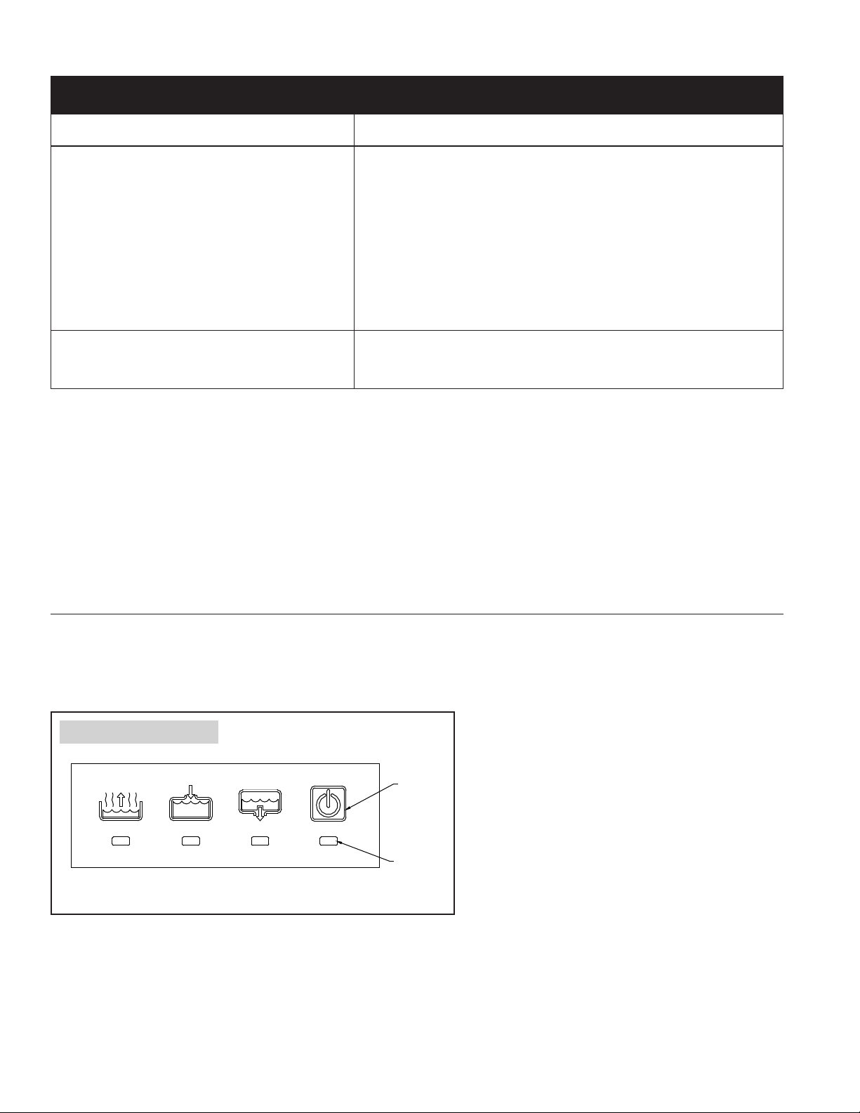
TABLE 3 – Sequence of operation for Model 1160 and 1180 (continued)
Operation Expected Results
• The humidifier will go into a forced cool-down period, which lasts about 6 hours for
Model 1160 and 7 hours for Model 1180. During that time, all the LEDs will blink in
sequence.
• After the forced cool down period, the Fill LED will turn on – the Fill valve will open,
If demand for humidity prevents the chamber from cooling,
a forced Autodrain sequence is initiated. During a forced
Autodrain sequence, the humidifier will not generate steam,
even if there is a call for humidity.
End of season drain.
water will flow into chamber until it reaches the upper probe.
• Drain LED will turn on and the drain valve will open allowing water to flow from the
bottom of the chamber.
• The drain valve will remain open for 12 minutes after the water level in the chamber
drops below the lower probe
• The Fill LED will turn on and the Fill valve will open.
• When the water in the chamber reaches the lower probe, if there is a demand for
humidity, the heating element will be energized·
• The Fill valve will remain open until the water in the chamber reaches the upper probe,
at which point the fill valve will close and the Fill LED will turn off.
• After 72 hours of no demand for humidity, the Drain LED will turn on and the drain
valve will remain open for 10 hours.
• After 10 hours, the Drain LED will turn off and the Drain valve will close.
• The chamber will remain empty until there is a demand for humidity.
DISPLAY PANEL AND INDICATOR LIGHTS
The display panel shows operating status and troubleshooting information. See the display panel detail (Figure 6) and the table
describing display panel lights (Table 4). For more information about blinking indicator lights, see the troubleshooting section in
this manual.
FIGURE 6 – Display Panel
On/Off
switch
Steam
Fill Drain On/Off
Indicator
light
OM-2028-M
10

TABLE 4 – Display Panel Light Indications
Indicator light(s) Status Description
All Blinking sequentially
On Power is on. Normal operation.
On/Off (switch)
Drain
Fill
Steam
Note:
See the Troubleshooting section in this manual for more information.
Slow blinking (1/sec.) The electronic water level probe needs cleaning.
Fast blinking (10/sec.) Probe logic fault. See Troubleshooting section.
On The humidifier is draining. Normal operation.
Blinking
On The humidifier is filling. Normal operation.
Blinking
On The humidifier is making steam. Normal operation.
Blinking
The humidifier is in a forced cool-down period prior to a required automatic drain sequence.
Normal operation.
The allowed amount of time for draining has been exceeded. Fault in drain operation.
Humidifier will continue to operate. See Troubleshooting section.
The allowed amount of time for filling has been exceeded. Fault in fill operation.
Humidifier will not operate. See Troubleshooting section.
The humidifier has received a demand signal but cannot make steam because:
• There is not enough water in the chamber, or
• An enable/safety switch is open
AUTODRAIN SEQUENCE
The humidifier drains and flushes automatically at regular intervals to remove minerals from the chamber.
After the humidifier has run for a preprogrammed amount of time, and if there is no demand for humidity, the humidifier sits idle
until the chamber cools and then it drains.
If the humidifier has not completed an autodrain sequence due to continual demand signal interruptions, after an additional
amount of run time the humidifier begins a cool-down period and then it drains.
IMPORTANT: The humidifier attempts to complete an autodrain sequence when there is no demand for humidity. However,
if an autodrain sequence is not completed within a defined period of time, the humidifier ignores the demand signal until
completing an autodrain sequence. This could cause the relative humidity level in the humidified space to drop until the autodrain
sequence completes.
11
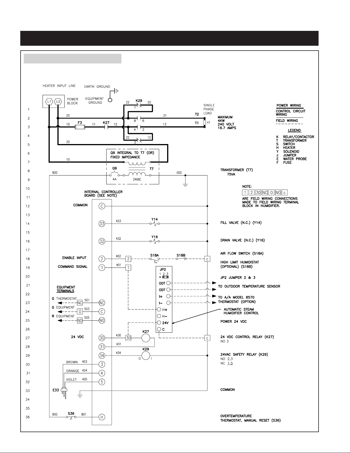
INSTALLATION
FIGURE 7 – Model 1150 Wiring Diagram
APRILAIRE STEAM HUMIDIFIER MODEL 1150
SINGLE HEATER WIRING DIAGRAM
ON/OFF CONFIGURATION
AA-LW420-1
12
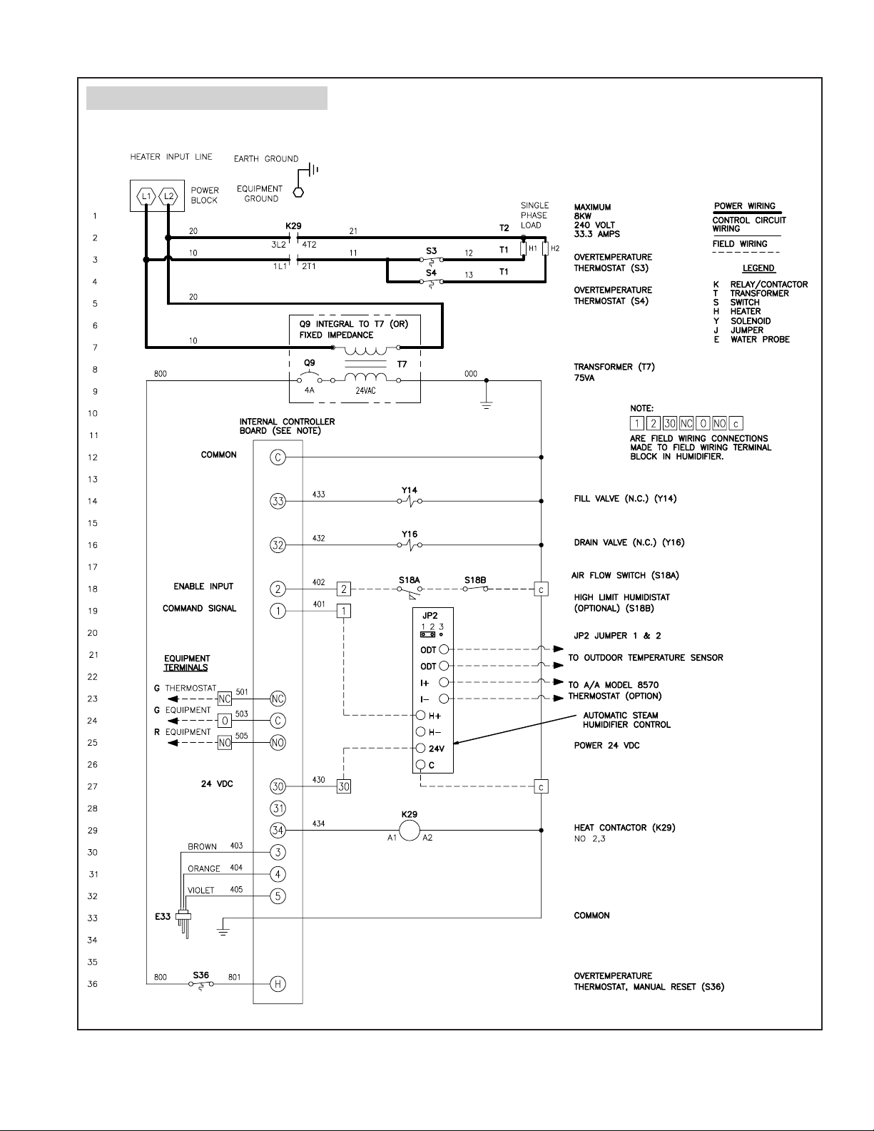
FIGURE 8 – Model 1160 Wiring Diagram
APRILAIRE STEAM HUMIDIFIER MODEL 1160
DUAL HEATER WIRING DIAGRAM
MODULATING CONFIGURATION
AA-LW420-2
13
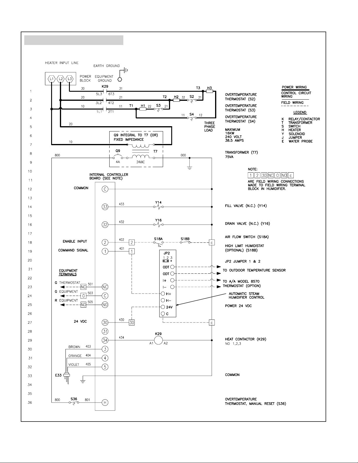
FIGURE 9 – Model 1180 Wiring Diagram
APRILAIRE STEAM HUMIDIFIER MODEL 1180
THREE HEATER WIRING DIAGRAM
MODULATING CONFIGURATION
AA-LW420-3
14
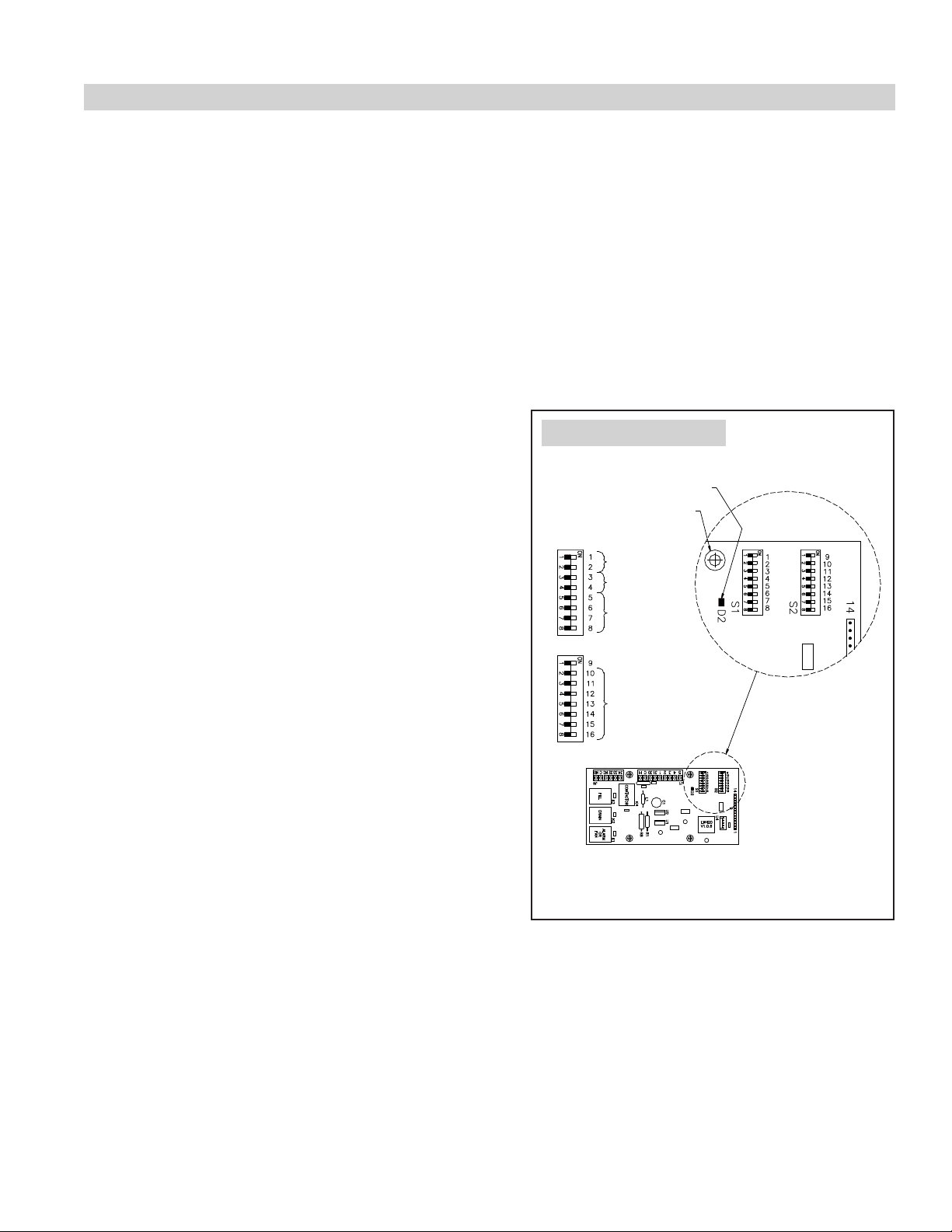
SETTING SLIDE SWITCHES
IMPORTANT: Slide switch on-off positions 1 through 16 are preset at the factory. These settings are determined
by output capacity, water type, and demand signal type. Changing these settings will affect humidifier operation.
Change on-off positions only per the instructions in this manual or as instructed by Aprilaire technical support staff.
On the internal controller inside the humidifier, there are two banks of slide switches. Most are set at the factory according to the
model type. Others, however, must be set according to the details of each particular installation. See Figure 10. Note: the ‘Off’
slide switch position is to the left while the ‘On’ slide switch position is to the right. For wiring details see page 27.
Type of Control Input
Model 1150 with an on/off control: S1 slide switch positions 1 and 2 Off
Model 1160/1180 with modulating control: S1 slide switch positions 1 and 2 Off
Model 1160/1180 with 0-10 VDC signal by others: S1 slide switch positions 1 and 2 Off
Model 1160/1180 with 4-20 mA signal by others: S1 slide switch positions 1 and 2 On
Inlet water type
The controller allows autodrain settings for three water supply types:
• Normal water (hardness greater than 4 and less than
FIGURE 10 – Slide Switches
10 grains/gallon)
• Hard water (hardness greater than or equal to 10 grains/gallon)
• Softened water (hardness less than or equal to 4 grains/gallon)
Position
S1
Type of
control input
Water type
The humidifier is preprogrammed for use with normal water. If your
water supply is hard or softened, follow the instructions below:
• For hard water supply (greater than or equal to 10 grains/gallon
of hardness):
– Set switch S1 position 3 to On; position 4 remains Off.
S2
Factory use only
Remote alarm or
fan/blower control
Factory use only
See Figure 10.
LED lamp
Mounting hole
• For softened water supply:
– Set switch S1 position 4 to On; position 3 remains Off.
See Figure 10.
Substituting a remote fault alarm for blower starting
The humidifier may be field programmed to send a fault alarm signal
to a remote device instead of sending a signal to start the HVAC
equipment blower.
Note:
Slide switches are shown in the off position.
Internal Controller Board
To enable this function, set slide switch S2 position 9 to On and
provide wiring to control terminals NO, O, and NC. See Figure 10 for slide switch positions.
If you change any on-off settings, record them in Table 5 for future reference.
OM-2038
15
 Loading...