

Aprilaire 1101 Owner's Manual
1. SELECT THE THERMOSTAT LOCATION
To ensure accurate temperature control, mount the thermostat
on an inside wall in a frequently occupied space that best
represents the building temperature. Mount the thermostat at
least 18" from any outside wall and approximately 5 ft. above
the floor.
DO NOT locate the thermostat:
.behind doors, in corners or other dead air spaces
.in direct sunlight or near lamps, appliances or other sources
of radiant heat
.on an outside wall or a wall exposed to an unconditioned
space (e.g., garage, etc.)
.in the flow path of a supply register, in stairways or near
outside doors
.on a wall where concealed pipes and/or ductwork will
affect the thermostat
.near sources of electrical interference such as arcing relay
contacts
2. UNLATCH THE THERMOSTAT PANEL
FROM THE BASE
Figure 1
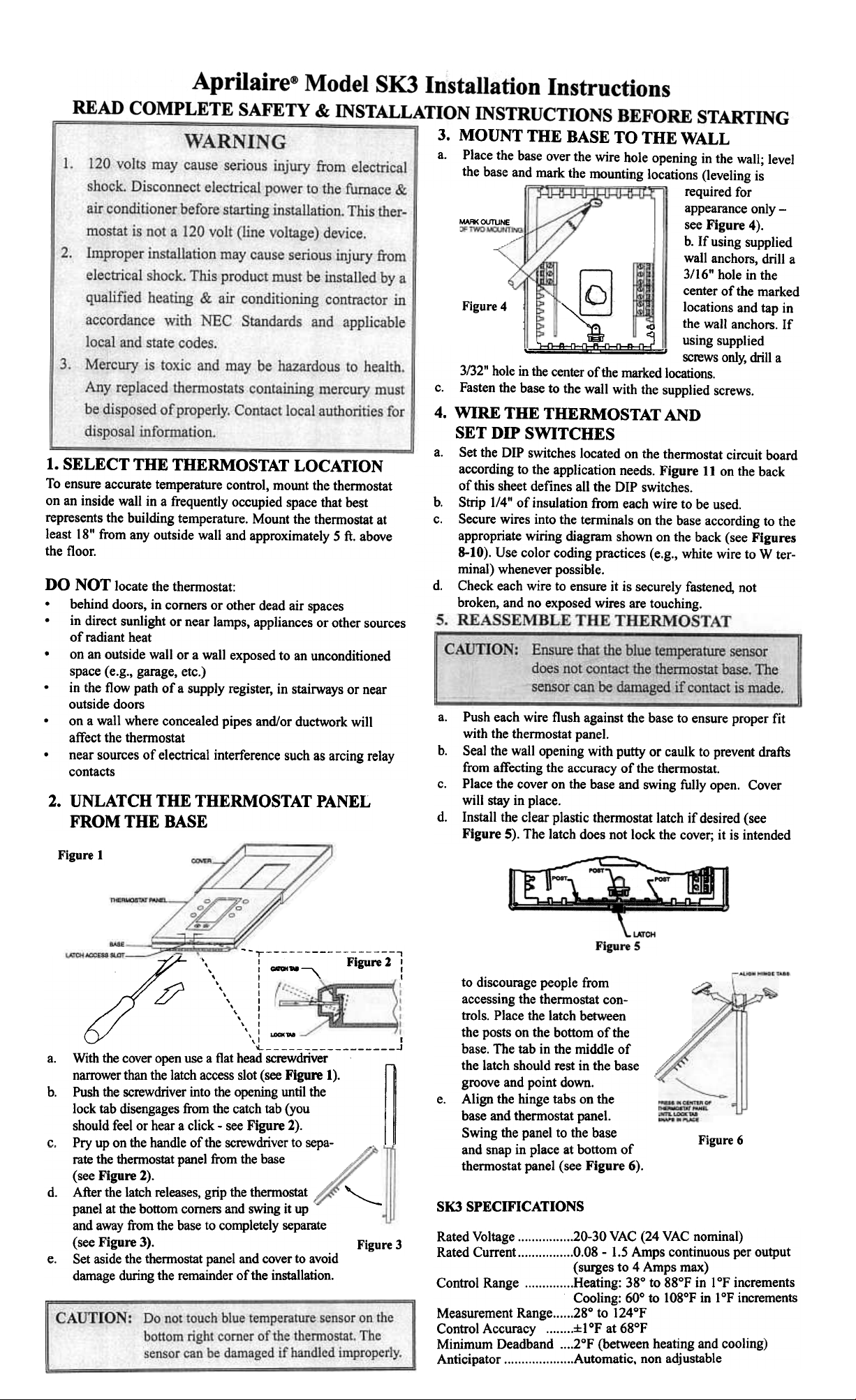
3. MOUNT THE BASE TO THE WALL
a. Place the base over the wire hole opening in the wall; level
the base and mark the mounting locations (leveling is
required for
appearance only -
MAR<OUTUNE
see Figure 4).
b. If using supplied
wall anchors, drill a
3/16" hole in the
center of the marked
Figure 4
""
locations and tap in
~ cO the wall anchors. If
~~~:!::I~. using supplied
screws only, drill a
3/32" hole in the center of the marked locations.
c. Fasten the base to the wall with the supplied screws.
4. WIRE THE THERMOSTAT AND
SET DIP SWITCHES
a. Set the DIP switches located on the thermostat circuit board
according to the application needs. Figure lIon the back
of this sheet defines all the DIP switches.
b. Strip 1/4" of insulation from each wire to be used.
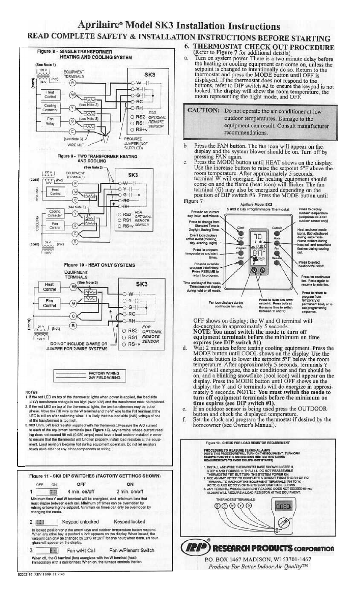
c. Secure wires into the terminals on the base according to the
appropriate wiring diagram shown on the back (see Figures
8-10). Use color coding practices (e.g., white wire to W terminal) whenever possible.
d. Check each wire to ensure it is securely fastened, not
broken, and no exposed wires are touching.
a. Push each wire flush against the base to ensure proper fit
with the thennostat panel.
b. Seal the wall opening with putty or caulk to prevent drafts
from affecting the accuracy of the thennostat.
c. Place the cover on the base and swing fully open. Cover
will stay in place.
d. Install the clear plastic thennostat latch if desired (see
Figure S). The latch does not lock the cover; it is intended
~-r ,
',I Figure 1 I
, I _N ~ I
, I " I
, I
" I
, I
, I
" I
, I
',I '-N
,I I
~ J
a. With the cover open use a flat head screwdriver
narrower than the latch access slot (see Figure 1).
b.
lock tab disengages from the catch tab (you
should feel or hear a click -see Figure 2).
Pry up on the handle of the screwdriver to sepa- .
c.
rate the thermostat panel from the base
(see Figure 2).
d. After the latch releases, grip the thermostat
panel at the bottom corners and swing it up
and away from the base to completely separate
(see Figure 3).
Set aside the thermostat panel and cover to avoid
e.
damage during the remainder of the installation.
"'-
Figure 3
to discourage people from
accessing the thermostat controls. Place the latch between
the posts on the bottom of the
base. The tab in the middle of
the latch should rest in the base
~Push the screwdriver into the opening until the
groove and point down.
e. Align the hinge tabs on the
base and thermostat panel.
Swing the panel to the base
and snap in place at bottom of
Figure 6
thermostat panel (see Figure 6).
SKJ SPECIFICATIONS
Rated Voltage 20-30 VAC (24 VAC nominal)
Rated Current 0.08 -1.5 Amps continuous per output
(surges to 4 Amps max)
Control Range Heating: 38° to 88°F in 1°F increments
Cooling: 60° to 108°F in 1°F increments
Measurement Range 28° to 124°F
Control Accuracy :f:loF at 68°F
Minimum Deadband 2°F (between heating and cooling)
Anticipator Automatic. non adjustable
~
 Loading...