

Page 1
6WC SERIES
MODELS
910WB & 910WE
IRON WAFER CHECK VALVE
INSTALLATION
OPERATION
MAINTENANCE
GUIDE
DOCUMENT NO.: ES-1545
REVISION LEVEL: A
ISSUED BY: Bill Hooks DATE: 09/25/13
APPROVED BY: _________________ DATE: _______
Page 2

APOLLO® WAFER CHECK VALVE IOM GUIDE Page 2 of 8
INTRODUCTION ......................................................................... 3
Table 1. Apollo Series & Model Numbers ................................................................... 3
Table 2. Apollo Pipe Size (x) Designations .................................................................. 3
Table 3. Apollo Wafer Check Valve Material Designation ............................................ 3
Pressure/Temperature Ratings ................................................................................. 3
Product Marking ...................................................................................................... 4
Figure 1. Apollo Wafer Check Valve Nameplate………………………………………………….4
INSTALLATION ........................................................................... 4
Installation Instructions ........................................................................................... 4
Figure 2. Apollo Iron Wafer Check Valve Horizontal Installation……………………………5
Figure 3. Apollo Iron Wafer Check Valve Vertical Installation….……………………………5
Table 4. Iron Flange – Class 125 stud sizes ............................................................... 6
Figure 4. Flange Bolt Tightening Sequence ................................................................ 6
OPERATION ............................................................................... 7
MAINTENANCE .......................................................................... 7
AMENDMENT REGISTER ............................................................. 8
ES1545 IOM Iron Wafer Check Valve 1418 S. Pearl Street Pageland SC USA 29728
Page 3
APOLLO® WAFER CHECK VALVE IOM GUIDE Page 3 of 8
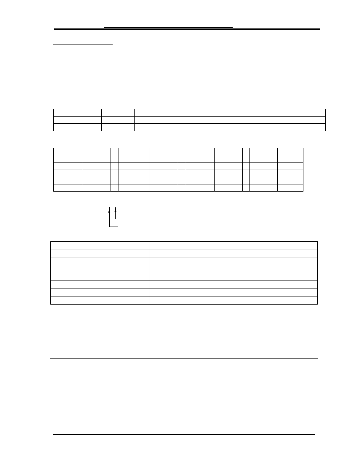
6WC-10x-x1
Size Code
Trim Code
SERIES
MODEL
DESCRIPTION
6WC-10x-N1
910WB
Class 125 Flanged Iron Wafer Check Valve Buna-N Seat
6WC-10x-E1
910WE
Class 125 Flanged Iron Wafer Check Valve EPDM Seat
Pipe
Size
Apollo
code
Pipe
Size
Apollo
code
Pipe
Size
Apollo
code
Pipe
Size
Apollo
code
2”
8 5”
B 12”
H 20”
N
2-1/2”
9 6”
C 14”
J 24” P 3”
0 8”
E 16”
K 4”
A 10”
G 18”
M
PART
MATERIAL
BODY
CAST IRON (ASTM A126 CL B)
SEAT RING
BUNA-N or EPDM
DISC
ALUMINUM BRONZE
SPRING
STAINLESS STEEL
STEM
STAINLESS STEEL
SCREW
CARBON STEEL
PIN
STAINLESS STEEL
INTRODUCTION
The APOLLO® Iron Wafer Check valves provide full flow capabilities. It provides
dependable and economical protection against reverse flow. It can reliably be installed in
most plumbing and heating systems (or building service piping).
Each valve is classified by its pressure rating. All valves designated as Class 125 comply
with MSS SP-71 Standard Practice.
Table 1. APOLLO® Series & Model Numbers
Table 2. APOLLO® Pipe Size (x) Designations
Example:
Table 3. APOLLO® Iron Wafer Check Valve Material Designation
Pressure/Temperature Ratings
Class 125
Saturated Steam (EPDM only): 125 psi (8.6 Bar) to 353°F(178°C) (2”-12”)
100 psi (6.9 Bar) to 338°F(170°C) (14”-24”)
Cold Working Pressure: 200 psi (13.8 Bar) at 100°F (2”-12”)
150 psi (10.3 Bar) at 100°F (14”-24”)
ES1545 IOM Iron Wafer Check Valve 1418 S. Pearl Street Pageland SC USA 29728
Page 4

APOLLO® WAFER CHECK VALVE IOM GUIDE Page 4 of 8
DATEPSIG(IN)
SIZE MAX MFG
3 200 0413 6WC100N1
910WB
MODEL
MADE IN CHINA
Product Marking
All APOLLO Wafer Check Valves are equipped with a nameplate attached to the valve
(Figure 1). This plate provides the model number, part number, size, max pressure
rating, and date of manufacture.
Figure 1. APOLLO IRON WAFER CHECK VALVE NAMEPLATE
INSTALLATION
APOLLO Wafer Check Valves are designed for use between the faces of ANSI 125 and
150 pound flat flanges. Raised faced flanges are not recommended.
To improve service life and efficiency, Wafer Check Valves are to be used in a steady flow
application. Wafer Check Valves are not recommended to be used in an application where
physical or thermal shock-load may be present.
Installation Instructions
Step 1. Check to make sure that the pipe flange and valve sealing faces are clean and
Step 2. Check the valve nameplate to ensure that the pressure and valve materials are
free from any debris (pipe scale, welding slag, etc.).
correct for the application.
WARNING! – APOLLO® Wafer Check Valves should never be installed where
service conditions could exceed the valve ratings. Failure to heed warning
may result in personal injury or property damage.
Step 3. Place the valve between the two flanges of the pipe and put the seal gasket
between the valve flange and the pipe flange; make sure that it is correctly
positioned.
Horizontal Installation: Check Valve should be installed with rib perpendicular to
the flow. See Figure 2 for Correct Horizontal Positioning.
Vertical Installation: Check Valve can only be installed vertically with flow
direction upward. Arrow on body indicates the correct direction of flow. Valve
should be installed with rib parallel to the incoming horizontal piping, so that it
creates equal loading on the plates. See Figure 3 for Correct Vertical
Positioning.
Step 4. To improve service life and efficiency, check valves should be installed 5 to 10
pipe diameters from any tees, elbows, pumps, swages, expansions and
reductions.
Step 5. Assemble the valve to the pipe using properly sized bolts for application. See
Table 4. Progressively tighten to the torque value recommended by the seal
gasket provider. See Figure 4 for recommended method.
After the valve installation on the line and before the line pressurization, the following
activities must be performed:
- the packing bolts must be verified for tightness, DO NOT OVERTIGHTEN.
- the valve must be fully stroke operated
ES1545 IOM Iron Wafer Check Valve 1418 S. Pearl Street Pageland SC USA 29728
Page 5

APOLLO® WAFER CHECK VALVE IOM GUIDE Page 5 of 8
Incorrect PositioningIncorrect PositioningCorrect Positioning
Incorrect Positioning
Correct Positioning
FLOW FLOW
FIGURE 2. APOLLO
FIGURE 3. APOLLO
Iron Wafer Check Valve Horizontal Installation
Iron Wafer Check Valve Vertical Installation
ES1545 IOM Iron Wafer Check Valve 1418 S. Pearl Street Pageland SC USA 29728
Page 6

APOLLO® WAFER CHECK VALVE IOM GUIDE Page 6 of 8
Valve
Size
Diameter
Length
Qty
(in)
(mm)
2 50
5/8”
3-1/2”
4
2.5
65
5/8”
3-3/4”
4 3 80
5/8”
3-3/4”
4 4 100
5/8”
3-3/4”
8 5 125
3/4”
4” 8 6
150
3/4”
4-1/4”
8 8 200
3/4”
4-1/2”
8
10
250
7/8”
4-3/4”
12
12
300
7/8”
5”
12
14
350
1”
5-1/2”
12
16
400
1”
5-1/2”
16
18
450
1-1/8”
16
20
500
1-1/8”
20
24
600
1-1/4”
20
Table 4. Stud/Bolt Iron Flange – Class 125
1 5 1 5
1 3 12 9
8 3
4 2 4 7
4 7
6 2
10 11
6 2
1 19
1 13 16 5
15 5
12 9
8 9
8 13
12 3
18 3
4 11
4 17
10 7
14 7
6 16
14 2 10 11
6 15
20 2
8 3
FIGURE 4. Flange Bolt Tightening Sequence
ES1545 IOM Iron Wafer Check Valve 1418 S. Pearl Street Pageland SC USA 29728
Page 7

APOLLO® WAFER CHECK VALVE IOM GUIDE Page 7 of 8
OPERATION
APOLLO® Iron Wafer Check valves are designed to prevent reverse flow in piping systems.
They are comprised of two spring loaded half-moon discs that open and close in response
to the inlet flow pressures and reverse flow pressures. When the required inlet pressure is
present disc will open. When there is inadequate inlet pressure the disc will close
preventing any reverse flow in the piping system.
MAINTENANCE
APOLLO® Iron Wafer Check valves are designed for extended service with minimal wear
and servicing. Replacement parts are not available.
WARNING! – The pipeline on either side of the valve MUST be depressurized and
drained prior to repair.
Valve Leakage
Valve should be periodically inspected for leakage. If the valve is found to be leaking,
check the flange bolt torque and the flange gasket. If leakage is still present, valve may
need to be removed to inspect the seating surfaces for imperfections.
No Flow
Inspect the Check Valves to make sure flow direction matches the directional arrow that
is cast on the body of the Check Valve.
Slamming
Check Valve will need to be removed to verify that the spring is providing the proper
tension.
Vibration
Confirm that the check valve is 5 to 10 pipe diameters from any turbulence producing
devices (tees, elbows, pumps, swages, expansions and reductions). Vibration can also be
caused if the flow rate is above the recommended range.
ES1545 IOM Iron Wafer Check Valve 1418 S. Pearl Street Pageland SC USA 29728
Page 8

APOLLO® WAFER CHECK VALVE IOM GUIDE Page 8 of 8
AMENDMENT REGISTER
DATE REV SECTION PAGE DESCRIPTION _
09/25/13 A All All Released new engineering
standard
10/10/13 B Introduction 3 Updated Pressure &
Temperature Ratings
ES1545 IOM Iron Wafer Check Valve 1418 S. Pearl Street Pageland SC USA 29728
 Loading...