


XP95 ENGINEERING PRODUCT GUIDE
Ionisation Smoke Detector
Optical Smoke Detector
Heat Detector
Multisensor Detector
Manual Call Point
Isolating Base
Sounders & Beacons

The XP95 range of intelligent fire detectors is advanced in design, improved in performance and has unique features that benefit the installer and the end user. The range includes ionisation and optical smoke detectors, heat detectors as well as a multisensor. All have an unobtrusive profile, a zero insertion force base, user friendly addressing and extended data and alarm features. A manual call point, an isolating base, sounders, beacons and other compatible products are also available.
These detectors have been carefully researched and developed by the Apollo design team and the range has undergone rigorous testing to ensure that it meets not only European and other standards but also the demands of today’s high technology environments.
This Product Guide aims to provide engineers with full information on XP95, in order to be able to design optimum solutions to fire protection problems.
Apollo Fire Detectors Limited, part of the Halma plc group of companies, operates from one site at Havant, near Portsmouth, England. All departments
– Research and Development, Sales and Marketing, Manufacturing and Finance – are located there. Apollo applies the most modern production techniques and has invested in sophisticated manufacturing equipment to ensure consistent high quality of product and fast response to customer requirements. Through planned expansion Apollo has reached a leading position in the market for professional fire detectors and exports over half of its production to countries around the world.
Key features
•Analogue Value Report
•Digital data transmission
•Input Bits Reporting
•Interrupt Warning
•Automatic Type Identification
•Address Confirmation
•XP95 Device Flag
Information in this guide is given in good faith, but Apollo Fire Detectors Limited cannot be held responsible for any omissions or errors. The company reserves the right to change specifications of products at any time without prior notice.
XP95 TABLE OF CONTENTS
Application of XP95 Detectors |
4 |
|
|
|
|
Addressing and Communications |
4 |
|
|
|
|
Features of the XP95 Range |
5 |
|
|
|
|
Ionisation Smoke Detector |
|
|
|
|
|
|
|
|
|
|
|
Operating principles |
6 |
|
|
|
|
Electrical description |
7 |
|
|
|
|
Environmental characteristics |
7 |
|
|
|
|
Safety note |
7 |
|
|
|
|
Technical data |
7 |
|
|
|
|
Optical Smoke Detector |
|
|
|
|
|
|
|
|
|
|
|
Operating principles |
9 |
|
|
|
|
Electrical description |
9 |
|
|
|
|
Environmental characteristics |
9 |
|
|
|
|
Technical data |
10 |
|
|
|
|
Heat Detector |
|
|
|
|
|
|
|
|
|
|
|
Operating principles |
11 |
|
|
|
|
Electrical description |
11 |
|
|
|
|
Environmental characteristics |
11 |
|
|
|
|
Technical data |
12 |
|
|
|
|
Multisensor Detector |
|
|
|
|
|
|
|
|
|
|
|
Operating principles |
13 |
|
|
|
|
Technical data |
14 |
|
|
|
|
Manual Call Point |
|
|
|
|
|
|
|
|
|
|
|
Operating principles |
15 |
|
|
|
|
Technical data |
16 |
|
|
|
|
XP95 Mounting Base |
17 |
|
|
|
|
|
|
|
|
|
|
XP95 20D Isolating Base |
|
|
|
|
|
|
|
|
|
|
|
Operating principles |
18 |
|
|
|
|
Electrical description |
18 |
|
|
|
|
Technical data |
18 |
|
|
|
|
XP95 Isolator |
19 |
|
|
|
|
XP95 Loop-Powered Beam Detector |
19 |
|
|
|
|
Intelligent Reflective Beam Detector |
19 |
|
|
|
|
MiniDisc Remote Indicator |
19 |
|
|
|
|
Loop-powered Sounders, Beacon & Sounder Beacons |
19 |
|
|
|
|
XP95 Flame Detector |
20 |
|
|
|
|
Approvals and Regulatory Compliance |
21 |
|
|
|
|
EMC |
21 |
|
|
|
|
Maintenance of Detectors |
22 |
|
|
|
|
|
|
|
|
|
|
|
|
|
|
|
|
page
3
page
4
APPLICATION OF XP95 DETECTORS
The choice of detector from the XP95 range follows the well established principles of system design. That is, the optimum detector type will depend on the type of fire risk and fire load, and the type of environment in which the detector is sited.
For general use, smoke detectors are recommended since these give the highest level of protection. Smoke detectors from the XP95 range may be ionisation, optical or multisensor types. It is generally accepted that ionisation types have a high sensitivity to flaming fires whereas optical detectors have high sensitivity to smouldering fires. As a result of this, ionisation types are widely used for property protection, and optical types for life protection. These general principles still apply to XP95 detectors although the availability of a multisensor in the range offers more choice to the system designer.
The multisensor is basically an optical smoke detector and will therefore respond well to the smoke from smouldering fires. The detector also senses air temperature. This temperature sensitivity allows the multisensor to give a response to fast burning (flaming) fires, which is similar to that of an ionisation detector. The multisensor can therefore be used as an alternative to an ionisation detector
Where the environment is smoky or dirty under normal conditions, a heat detector may be more appropriate. It must be recognised, however, that any heat detector will respond only when the fire is well established and generating a high heat output.
Unless otherwise specified, devices described in this guide are suitable for indoor use only.
ADDRESSING AND COMMUNICATIONS
Each XP95 device responds to interrogation and command from central control equipment. It communicates to the panel information on status, command bits, type, location, and other information that allows an alarm to be raised even when the device is not itself being interrogated. Message error checking is also provided. The devices are compatible with Series 90, Discovery® and XPlorer systems and control equipment to aid maintenance, extension and upgrade of existing systems.
A unique, patented XPERT card provides simple, user friendly and accurate identification of detector location whereby a coded card, inserted in the base, is read by any detector once it is plugged in. All the electronic
components are in the detector but the location information is held in the base. The address card simplifies and speeds up installation and commissioning. Addressing errors during maintenance and service are eliminated.
The XP95 manual call point continues to use DIL switch addressing, but its interrupt feature also provides automatic reporting of its location in the interrupt mode.
The XP95 detectors provide an alarm facility that automatically puts an alarm flag on the data stream and reports its address when the pre-set EN54 thresholds are exceeded. The devices provide great flexibility in system design with the control equipment determining the characteristics of the system. A large and growing range of compatible control equipment is available from many sources - details are included in Apollo publication PP1010, which is available on request.

|
Ionisation |
Optical |
Multisensor |
Heat |
|
|
|
|
|
Overheating/thermal combustion |
Poor |
Very Good |
Very Good |
Very Poor |
Smouldering/glowing combustion |
Moderate/Good |
Good |
Good |
Very Poor |
Flaming combustion |
Very Good |
Good |
Good |
Poor |
Flaming with high heat output |
Very Good |
Good |
Very Good |
Moderate/Good |
Flaming - clean burning |
Poor |
Very Poor |
Moderate/Good |
Moderate/Good |
|
|
|
|
|
Table1 |
Response characteristics of smoke and heat detectors. |
PROTOCOL FEATURES |
ENGINEERING FEATURES |
Control Unit Interrogation and Command:
3 bits of command instruction and the 7- bit address are issued by the control equipment following an initiatingpulse.
Interrupt Warning:
Notification that an XP95 manual call point or XP95 Mini Switch Monitor (interrupt) has been operated.
Analogue Value Report:
Status continually reported.
Input Bits Reporting:
Field devices advise control equipment of actions they have taken. For smoke and temperature detectors, these confirm compliance with the output command bits. Bit information depends on device type.
Automatic Type Identification:
The device being interrogated replies with a 5 bit type code, allowing up to 32 device types.
Address Confirmation:
The 7- bit address (up to 126 devices per loop) of the detector responding is confirmed back to the control unit.
XP95 Device Flag:
Tells the control equipmentthat more informationis available.
Alarm Flag:
For accelerated alarm reporting.
Parity Error Check:
For received message accuracy.
Interrupt or Alarm Address:
Provides fast location of a device in alarm state.
High Level Integration:
ASICs technology for lower component count.
Zero Insertion Force Base:
For easier installation and maintenance.
Ease of Maintenance:
Snap lock chambers for easy cleaning.
Surface Mounted Components:
For long life and high reliability
Latest Data Reported:
As well as free running data update, device will update data when the preceding device is being interrogated.
XPERT Card Addressing:
For fast reliable installation and service.
Unobtrusive Design:
For elegant designs in modern buildings.
page
5
XP95 IONISATION SMOKE DETECTOR
page
6
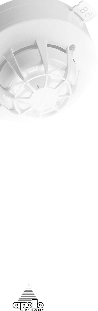
XP95 Ionisation Smoke Detector |
Part Number 55000-500 |
OPERATING
PRINCIPLES
The XP95 ionisation smoke detect or has a moul ded self-extinguishing white polycarbonate case with wind resistant smoke inlets. Stainless steel wiper contacts connect the detector to the terminals in the mounting base. Inside the detector case is a printed circuit board that has the ionisation chamber mounted on one side and the address capture, signal processing and communications electronics on the other.
The ionisation chamber system is an inner reference chamber contained inside an
outer smoke chamber (Fig 1). The outer smoke chamber has smoke inlet apertures that are fitted with an insect resistant mesh.
The radioactive source holder and the outer smoke chamber are the positive and negative electrodes respectively. An Americium 241 radioactive source mounted within the inner reference chamber irradiates the air in both chambers to produce positive and negative ions. On applying a voltage across these electrodes an electric field is formed as shown in Fig 2. The ions are attracted to the electrode of the opposite sign, some ions collide and recombine, but the net result
Fig.1 Sectional view - XP95 Ionisation Smoke Detector
is that a small electric current flows between the electrodes. At the junction between the reference andsmoke chambers is the sensing electrode that is used to convert variations in the chamber currents into a voltage.
When smoke particles enter the ionisation chamber, ions become attached to them with the result that the current flowing through the ionisation chamber decreases. This effect is greater in the smoke chamber than in the reference chamber and the imbalance
causes the sensing electrode to go more positive.
The voltage on the sensing electrode is monitored by the sensor electronics and is processed to produce a signal that is translated by the A/D converter in the communications ASIC ready for transmission when the device is interrogated.
Fig.2 Diagramshowinglinesofequipotential fortheXP95 IonisationSmokeMonitor
ELECTRICAL
DESCRIPTION
The detector is designed to be connected to a two wire loop circuit carrying both data and a 17V to 28V dc supply. The detector is connected to the incoming and outgoing supply via terminals L1 and L2 in the mounting base. A remote LED indicator requiring not more than 4mA at 5V may be connected between+R and -R terminals. An earth connection terminal is also provided, although this is not required for the functioning of the detector.
When the device is energised the ASICs regulate the flow of power and control the data processing. The ionisation chambers are energised and the ultra low leakage sensor ASIC provides a conditioned analogue signal to the analogue to digital (A/D) converter within the communications and processing ASIC. When smoke enters the ionisation chambers through the integral gauze, the voltage at the sensingelectrodeincreasesto producean analoguesignal. An A/D conversion of the signal from the ionisation chambers is carried out once per second or when either the detector or preceding address is being interrogated. Whenever the device is interrogated this data is sent to the control equipment. EN54 threshold alarm levels are calibrated within the processing ASIC. If the device is not addressed within 1 second of its last polling and the analogue value is greater than 55 the
alarm flag is initiated and the device address is added to the data stream every 32 polling cycles from its last polling for the duration of the alarm level condition, except when the alarming
device is being interrogated. |
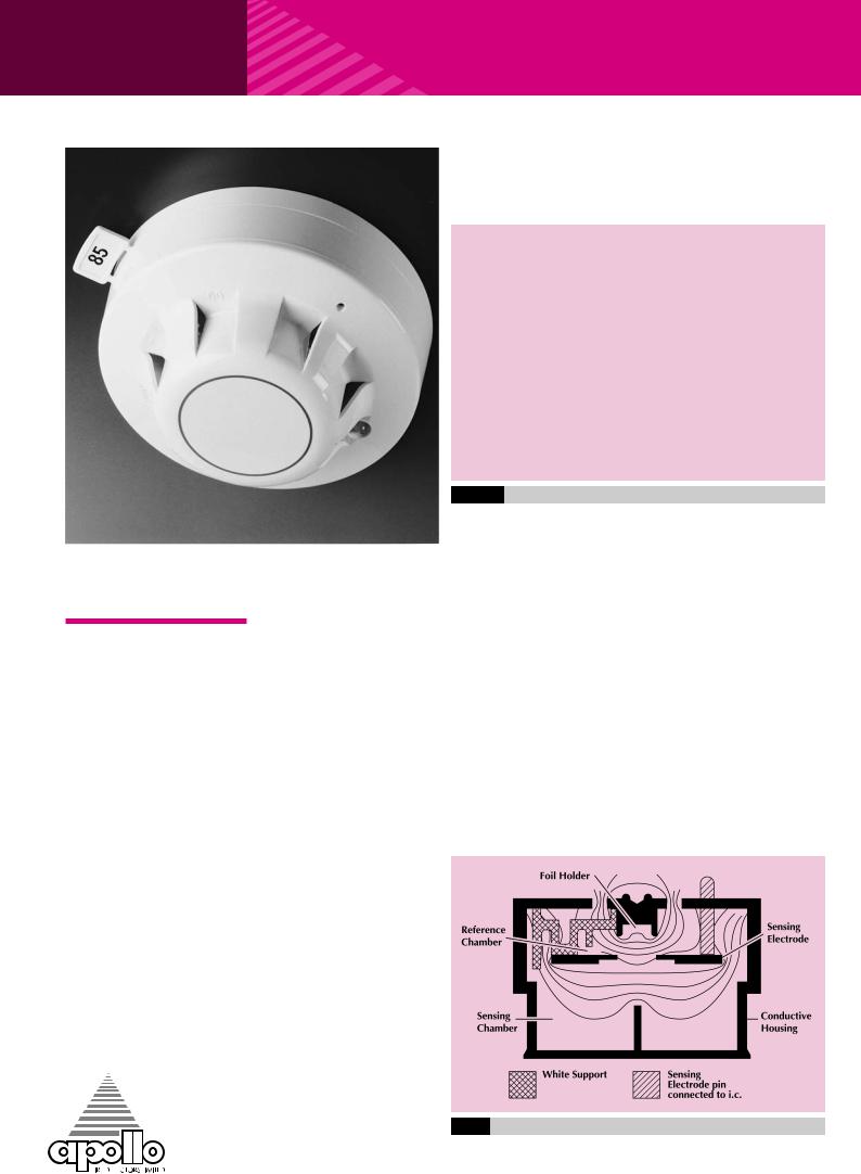
Fig.3 |
Typical response characteristics - XP95 Ionisation Detector |
||
This can provide a location |
|
|
|
|
identified alarm from any |
|
|
|
|
device on the loop in |
|
|
|
|
|
|
|
|
|
approximately two seconds. |
|
|
|
|
|
|
|
|
|
The detector is calibrated to give an analogue value of 25±7counts in clean air. This value increases with smoke density. A count of 55 corresponds to the EN54alarm sensitivity level. See Fig 3. Counts of 8 or less indicate faultconditions. Countlevels between 45 counts and 55
countscan be used to provide
Fig.4 Typical temperature response - XP95 Ionisation Detector
an early warning of fire.
ENVIRONMENTAL CHARACTERISTICS
XP95 ionisation smoke detectors are designed to operate in a wide variety of environments (See Figs 4 to 6). There are only small effects from temperature, humidity, atmospheric pressure and wind. Detectors are well protected against electromagnetic interference over a wide frequency range.
The XP95 ionisation detector, like all ionisation detectors,
has some sensitivity to air movement (wind). The extent to which the analogue value will change depends
on the wind speed and on the orientation of the
detector relative to the wind  direction. Relatively small
 changes in wind direction
  can cause significant changes
in analogue value.
Fig.5 Typical pressure response - XP95 Ionisation Detector
|
|
|
|
|
|
|
|
|
|
|
|
|
|
|
|
|
|
|
|
|
|
|
|
Fig.6 |
|
|
Typicalwind speedresponseXP95 IonisationSmokeDetector |
||
|
|
|
page
7

page
8
TECHNICAL DATA |
Supply Wiring: |
||
|
Two wire supply, polarity |
||
XP95 Ionisation |
insensitive |
||
Terminal Functions: |
|||
Detector Part No 55000-500/ |
L1&L2 |
supply in and out |
|
520/560 |
|
connections (polarity |
|
Base Part No 45681-210 |
|
insensitive) |
|
Specifications are typical |
+R |
remote indicator |
|
|
positive connection |
||
and given at 23°C and 50% |
|
(internal 2.2kΩ |
|
relative humidity unless |
|
resistance to supply |
|
otherwise stated. |
|
+ve) |
|
Detector Type: |
-R |
remote indicator |
|
|
negative connection |
||
Point type smoke detector for |
|
||
|
(internal 2.2kΩ |
||
fire detection and fire alarm |
|
||
|
resistance to supply |
||
systems for buildings |
|
||
|
- ve) |
||
Detection Principle: |
|
||
Supply Voltage: |
|||
Ionisation Chamber |
|||
17 to 28 Volts dc |
|||
Chamber Configuration: |
|||
Modulation Voltage at |
|||
Twin compensating |
|||
Detector: |
|||
chambers using one single |
|||
5 to 9 Volts peak to peak |
|||
sided ionising radiation |
|||
|
|
||
source |
Quiescent Current: |
||
Radioactive Isotope: |
280µA average, 500µA peak |
||
|
|
||
Americium 241 |
Power-up Surge Current: |
||
Activity: |
1mA |
|
|
|
|
||
33.3kBq, 0.9µCi |
Duration of Power-up Surge |
||
Sampling Frequency: |
Current: |
|
|
0.3 seconds |
|||
Continuous |
|||
Maximum Power-up Time: |
|||
Sensitivity: |
|||
4 seconds for communications |
|||
Nominal threshold y value of |
|||
(measured from application of |
|||
0.7 to EN54–7:2000 |
|||
power and protocol) |
|||
|
|||
technical |
|||
10 seconds to exceed 10 counts 15 seconds for stable clean air value
Clean Air Analogue Value:
25±7 counts
Alarm Level 55 Counts:
EN54 y value of 0.7
Alarm Indicator:
Red light emitting diode (LED)
Alarm LED Current:
2mA
Remote LED Current:
4mA at 5V (measured across remote load)
Type Code:
(210 43) 011 00
Storage Temperature:
-30°C to +80°C
Operating Temperature:
-20°C to +70°C
Guaranteed Temperature Range:
(No condensation or icing)
-20°C to +60°C
Humidity:
(No condensation or icing)
0% to 95% relative humidity
Wind Speed:
10m/s maximum
data
Atmospheric Pressure:
Automatic compensation by dual chambers to maintain sensitivity up to a height of 2000m above sea level
Vibration, Impact & Shock:
To EN54–7:2000
Electro-magnetic Compatibility:
See page 21 for full details
IP Rating:
23D
Approvals & Regulatory Compliance:
See page 21 for full details
Dimensions: (diameterx height) Detector: 100mm x 42mm Detector in Base:
100mm x 50mm
Weights:
Detector: 105g
Detector in Base: 161g
Materials:
Detector Housing: White polycarbonate V-0 rated to UL 94
Terminals: Nickel plated stainless steel
0832
For wind speeds up to 1m/s (200ft/min) the change in analogue value will not exceed 5 counts. Continuous operation in wind speeds greater than 2m/s (400ft/min) is not recommended. However, wind speeds up to 10m/s (2000ft/min) can be tolerated for short periods and will not under any conditions increase the probability of false alarms.
SAFETY NOTE
In the United Kingdom, ionisationsmokedetectorsare subject to the requirements of the Radioactive Substances Act 1993 and to the Ionising Radiations Regulations 1999 made under the provisions of the Health and Safety at Work Act 1974.
The detectors,independently tested by the National Radiological Protection Board (NRPB), conform to all the requirements specified in the ‘Recommendations for ionisation smoke detectors in implementation of radiation standards’ published by the NuclearEnergyAgencyof the
Organisation for Economic Co-operation and Development (OECD) 1977.
Thereis no limit to the number of ionisation smoke detectors which may be installed in any fire protection system within the UK. See Certificate of Approval No. TA1 of 1999 issues by the HSE for further details.
Storage regulations depend on local standards and the legislation, but, in the UK, the number of ionisation smoke detectors in any building or premises shall be less than 500. See Certificate of Approval No. TA3 of 1999 issued by the HSE for further details.
At the end of their recommended working life
of ten years, ionisation smoke detectors should be returned to Apollo for safe disposal or disposed of in an otherwise locally approved and environmentally safe manner. Please see "A Guide to the Care, Maintenance and Servicing of Apollo Products", PP2055.
Guidance on storage can be given by Apollo Fire Detectors and full details can be requested from:
Radioactive Substances
Regulation Function
Environment Agency
Rio House, Waterside Drive
Aztec West, Almondsbury,
Bristol, BS32 4UD
Outside the UK, please contact the relevant national agency.
 Loading...