

Page 1
APG
Thank You
Thanks for purchasing a Series FS-400 or FS-410 Float Switch from us! We appreciate your business
and your trust. Please take a moment to familiarize yourself with the product and this manual
before installation. If you have any questions, at any time, don’t hesitate to call us at 888-525-7300.
Vertical Stainless Steel Float Switch
Installation Guide
NOTE: Scan the appropriate QR code below to see the datasheet with full specs on your
tablet or smartphone. Or visit www.apgsensors.com/support to nd it on our website.
FS-400 Datsheet (Doc #9005500) FS-410 Datasheet (Doc #9005501)
Table of Contents
1.Description
2. How To Read Your Label
3. Warranty
Description
1
Series FS-400 Stainless Steel Vertical Float Switches and Series FS-410 Miniature Stainless Steel
Vertical Float Switches are durable oat switches with a wide range of uses. Both are compact,
feature all stainless steel wetted materials, and have user-reversible switch orientation. All FS-400 &
FS-410 switches are made in the USA.
4. Installation Instructions
5. Dimensions
6. Reversing Switch Operation
(NO/NC)
7. General Care
8. Repair Information
9. Removal Instructions
Series FS-400 & FS-410
R
Automation Products Group, Inc.
1025 W 1700 N Logan, UT 84321
www.apgsensors.com | phone: 888-525-7300 | email: sales@apgsensors.com
Warranty
3
This product is covered by APG’s warranty to be free from defects in material and workmanship
under normal use and service of the product for 24 months. For a full explanation of our Warranty,
please visit https://www.apgsensors.com/about-us/terms-conditions. Contact Technical Support to
receive a Return Material Authorization before shipping your product back.
Doc #9005502 Rev B
Part #200216
FS-400 & FS-410 switches should be installed in an area--indoors or outdoors--which meets the
following conditions:
• Ambient temperature between -40°F and 368°F (-40°C to 187°C); up to 500°F (260°C) for HT
• Process pressure 200 psi (13.8 bar) or less (FS-400-S); 500 psi (34.5 bar) or less (FS-400-HT);
or 300 psi (20.7 bar) or less (FS-410)
• Relative humidity up to 100%
• Altitude up to 2000 meters (6560 feet)
• No chemicals corrosive to stainless steel (such as NH
How To Read Your Label
2
Each label comes with a full model number, a part number, and a serial number. The model
number for the Series FS-400 or FS-410 Float Switch will look something like this:
SAMPLE: FS-400-HT-M1-M1-0.6-P0-48
The model number correlates with all the congurable options and tells you exactly what you have.
Compare the model number to the options on the datasheet to identify your exact conguration.
You can also call us with the model, part, or the serial number and we can help you.
, SO2, Cl2, etc.)
3
Scan the QR code below to read the full explanation of our Warranty on your tablet or smartphone.
Installation Instructions
4
Installing your vertical oat switch is easy if you follow a few simple steps:
• Hold the switch beneath where it will mount, and feed the wires up through the mount.
• Insert the threads into the mount and begin to turn by hand.
• Use an appropriately sized wrench on the hex nut to completely tighten the threads.
• Connect the switch wires to your control system.
• Equipment must be grounded through nal installation.
• Adequate overcurrent protection must be provided at the supply.
Page 2
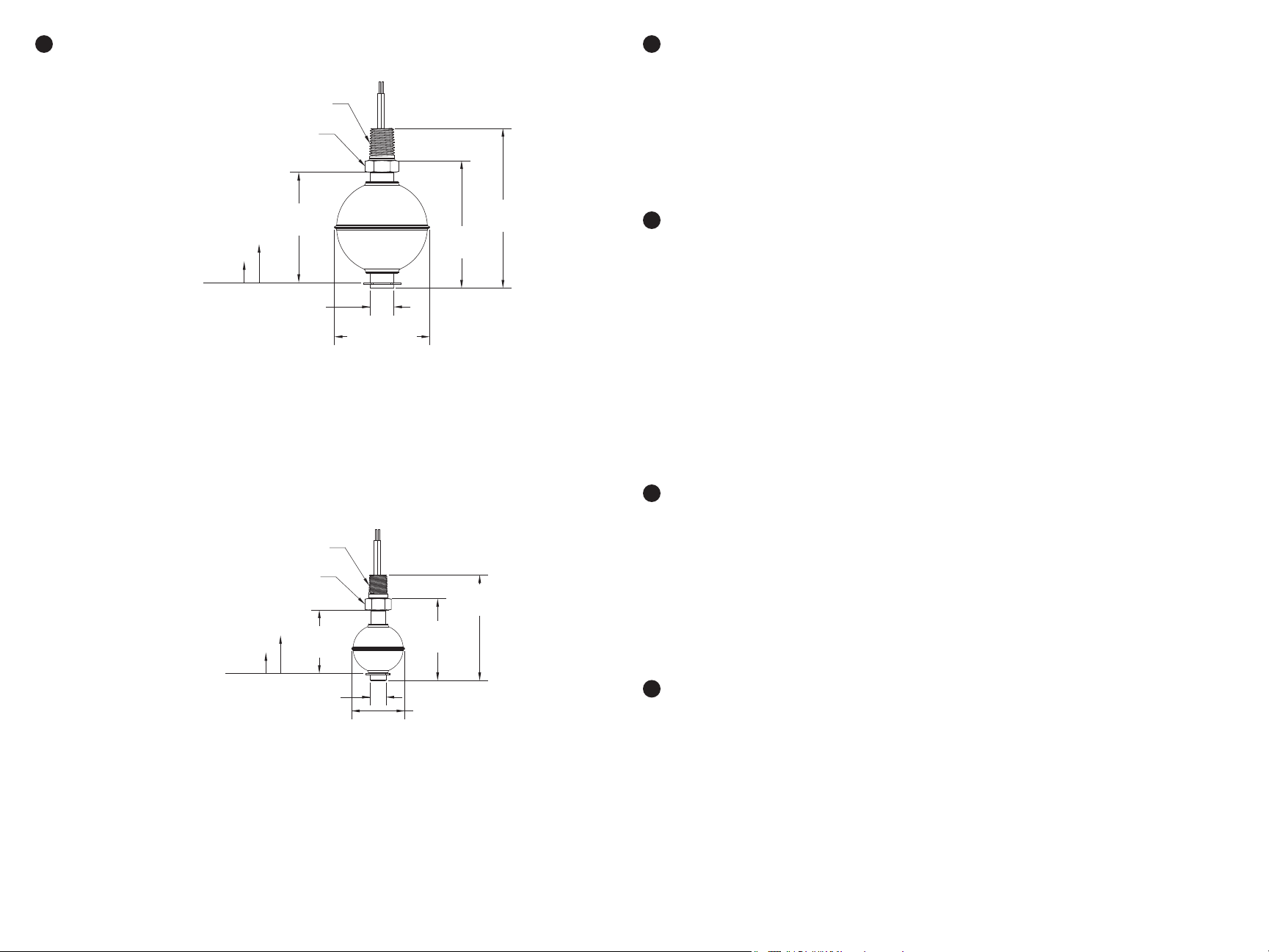
Dimensions
5
1/4" NPTM
5/8" Hex Nut
Reversing Switch Operation (NO/NC)
6
All Series FS-400 and FS-410 Float Switches ship from the factory oriented for NO operation. To
change the switch to NC:
1. Remove the e-clip at the bottom of the oat stem.
2. Remove the oat, and turn it over.
3. Replace the re-oriented oat
4. Replace the e-clip.
NO Accuation: 0.220" ± 0.015"
NC Accuation: 0.160" ± 0.015"
NO Accuation: 0.130" ± 0.015"
NC Accuation: 0.115" ± 0.015"
2.38"
[60.48mm]
0.50"
[12.70mm]
[52.32mm]
FS-400 Dimensions
1/8" NPTM
1/2" Hex Nut
1.39"
[35.34mm]
0.34"
[8.64mm]
2.06"Ø
2.75"
[69.85mm]
[58.93mm]
1.80"
[45.72mm]
1.17"Ø
[29.72mm]
3.44"
[87.49mm]
2.32"
General Care and Notes
7
Your oat switch is very low maintenance and will need little care, as long as it was installed
correctly. However, in general, you should:
• Keep the oat arm and support arm generally clean.
• Avoid applications for which the switch was not designed, such as contact with incompatible
corrosive chemicals, or other damaging environments.
• Inspect the threads whenever you remove the switch from duty or change its location.
See datasheets (FS-400, Doc #9005500; FS-410, Doc #9005501) for the following specications:
• Specic Gravity
• Actuation Angle and Hysteresis
• Electrical power rating, voltage ranges with frequencies and currents
• Full Hazardous Location ratings statements
Repair Information
8
If your oat switch needs repair, contact us via email, phone, or on-line chat on our website. We will
issue you an RMA number with instructions.
• Phone: 888-525-7300
• Email: sales@apgsensors.com
• Online chat at www.apgsensors.com
Removal Instructions
9
Removing your oat switch from service must be done with care. It’s easy to damage your switch if
you are not careful to follow these guidelines:
FS-410 Dimensions
• Make sure the liquid is well below the level of the switch. Follow any and all procedures for
safely isolating any media contained inside the line or vessel.
• Disconnect wires to switch.
• Loosen the switch with an appropriately sized wrench.
• Twist switch until completely free of threads.
• Pull wires out through mounting.
• Store your switch in a dry place, at a temperature between -40° F and 180° F.
 Loading...