

Page 1

APG
Hammer Union Pressure Transmitter
User Manual
For The Recalibratable HU1502I
Doc #9005223
R
Part #200073
Rev C, 01/19
Page 2

Table of Contents
Introduction ................................................................................................................ iii
Warranty and Warranty Restrictions .................................................................... iv
Chapter 1: Specications and Options.....................................................................1
Dimensions ........................................................................................................................................1
Specications ...................................................................................................................................2
Model Number Congurator .......................................................................................................... 3
Electrical Connectors and Pinout Table .....................................................................................4
Chapter 2: Installation and Removal Procedures and Notes ..............................5
Tools Needed .....................................................................................................................................5
Physical Installation ....................................................................................................................... 5
Electrical Installation ..................................................................................................................... 5
Shunt Calibration Procedures ....................................................................................................... 6
Removal Instructions .....................................................................................................................6
Chapter 3: Maintenance .............................................................................................7
General Care ...................................................................................................................................... 7
Repair and Returns .......................................................................................................................... 7
Chapter 4: Recalibration Procedure .........................................................................8
Recalibration Wiring Diagrams .................................................................................................... 8
Tools Needed .....................................................................................................................................9
Recalibration Set Up - Computer ..................................................................................................9
Recalibration Set Up - HU1502SS/I ..............................................................................................9
Software User Interface ........................................................................................................... 10-11
Recalibration Procedure .......................................................................................................... 11-12
Chapter 5: Hazardous Location Installation and Certication ......................... 13
Intrinsically Safe Wiring Diagram ............................................................................................. 13
CSA Certicate of Compliance ...............................................................................................14-17
EU Declaration of Conformity ..................................................................................................... 18
IECEx Certicate of Conformity ............................................................................................19-23
ii
Tel: 1/888/525-7300 • Fax: 1/435/753-7490 • www.apgsensors.com • sales@apgsensors.com
Page 3
Introduction
Thank you for purchasing a Hammer Union Pressure Transmitter from APG. We appreciate your business!
Please take a few minutes to familiarize yourself with your Hammer Union and this manual.
APG’s Recalibratable Hammer Union Pressure Transmitters are designed for the harsh environments of
land-based and oshore drilling installations. Designed specically for use with the 1502 Hammer Wing
Union, the HU1502I features a NPT-sealed port for digital zero and span recalibration. The HU1502I is
constructed from NACE compliant incoloy for use with sour gas (H2S), soduim chloride (NaCl), calcium
chloride (CaCl2), and in corrosive environments.
Reading your label
Every APG instrument comes with a label that includes the instrument’s model number, part number, serial
number, and a wiring pinout table. Please ensure that the part number and pinout table on your label
match your order.
Electrical ratings
Input: 10 to 28 VDC; Output: 4-20 mA / 0-5 VDC (per order)
Class I, Division 1, Groups C, D
Class I, Zone 0
Ex ia IIB T4: -40°C to 85°C; Enclosure Type IP67
AEx ia IIB T4: -40°C to 85°C; Enclosure Type IP67
Vmax Ui= 28VDC, Imax Ii = 110mA, Pmax Pi = 1W, Ci = 60.89nF, Li = 7.7mH
The following approvals only apply to the L24 (4-20mA) version
ATEX Directive:
Sira 13ATEX2023
II 1G Ex ia IIB T4 Ga
Ta: -40°C to 85°C
Ui ≤ 28 V, Ii ≤ 110 mA, Pi ≤ 1 W, Ci ≤ 60.89 nF, Li ≤ 7.7 mH
IECEx CSA 13.0004
Ex ia IIB T4 Ga
0344
IMPORTANT: Recalibratable Hammer Union Pressure Transmitter MUST be installed
according to drawing 9002460 (Intrinsically Safe Wiring Diagram) on page 13 to meet listed approvals. Faulty installation will invalidate all safety approvals and ratings.
Tel: 1/888/525-7300 • Fax: 1/435/753-7490 • www.apgsensors.com • sales@apgsensors.com
iii
Page 4
Warranty and Warranty Restrictions
This product is covered by APG’s warranty to be free from defects in material and workmanship under
normal use and service of the product for 24 months. For a full explanation of our Warranty, please visit
https://www.apgsensors.com/about-us/terms-conditions. Contact Technical Support to receive a Return
Material Authorization before shipping your product back.
Scan the QR code below to read the full explanation of our Warranty on your tablet or smartphone.
iv
Tel: 1/888/525-7300 • Fax: 1/435/753-7490 • www.apgsensors.com • sales@apgsensors.com
Page 5
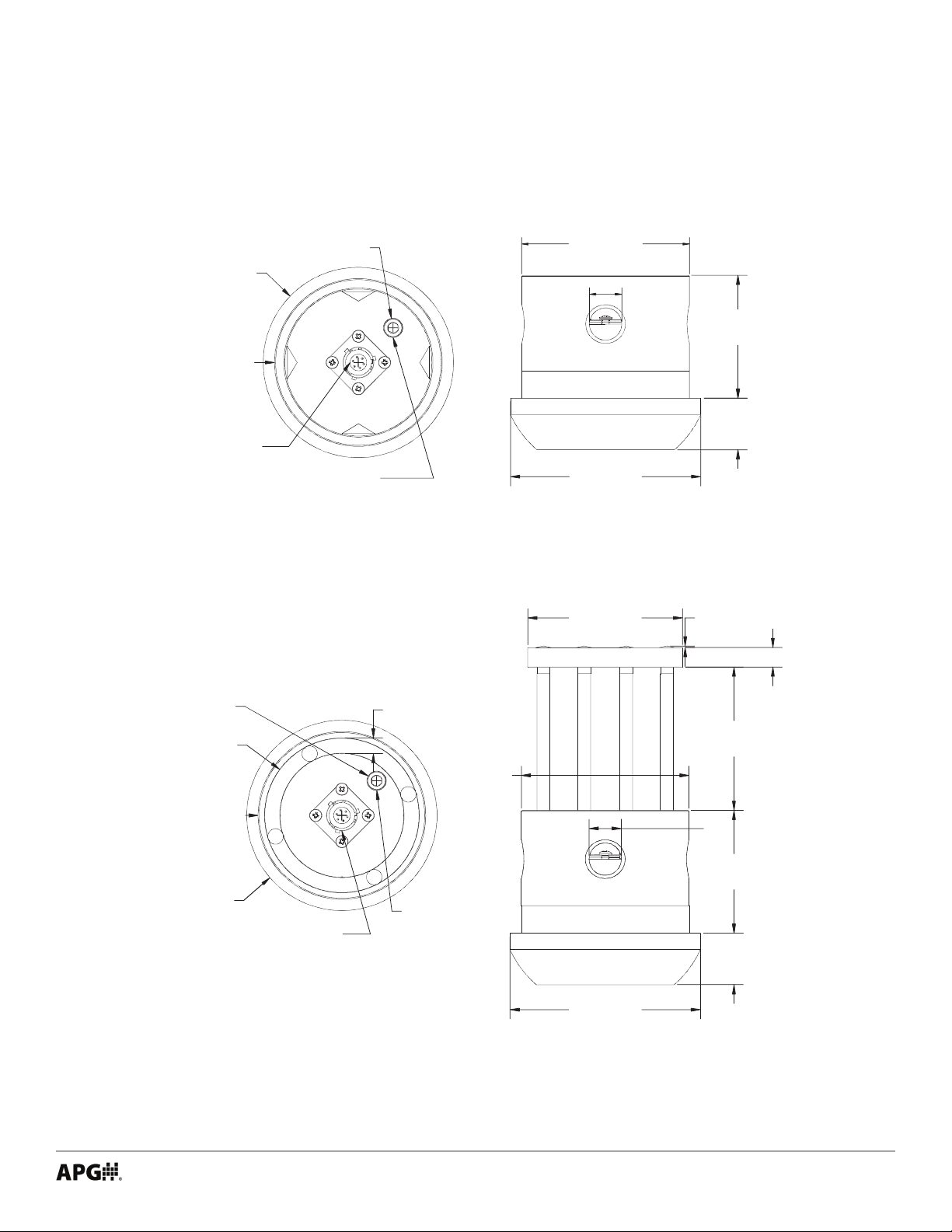
Chapter 1: Specications and Options
• Dimensions
ø3.69"
[ø93.70mm]
ø3.25"
[ø82.50mm]
6 pin bayonet
connector
ø0.37"
[ø9.50mm]
Recalibration
Port
[82.50mm]
0.63"
[15.90mm]
[93.70mm]
[76.20mm]
3.25"
3.69"
3.00"
2.38"
[60.50mm]
1.00"
[25.40mm]
0.03"
[0.80mm]
0.38" [9.70mm]
ø0.37"
[ø9.50mm]
ø3.00"
[ø76.20mm]
ø3.25"
[ø82.50mm]
ø3.69"
[ø93.70mm]
6 Pin Bayonet
Connector
0.30"
[7.60mm]
2.78"
[70.50mm]
3.25"
[82.50mm]
0.63"
[15.90mm]
2.38"
[60.50mm]
Recalibration
Port
1.00"
[25.40mm]
3.69"
[93.70mm]
Tel: 1/888/525-7300 • Fax: 1/435/753-7490 • www.apgsensors.com • sales@apgsensors.com
1
Page 6

• Specications
Performance
Pressure Ranges 0 to 20K PSIS (Per Part Number)
Analog Output 4-20mA, 0-5VDC
Over Pressure 1.5X Full Scale, or limit of wing nut tting, whichever is
Burst Pressure 3.0X Full Scale, or limit of wing nut tting, whichever is
Life 10 million cycles, minimum
Accuracy
Linearity, Hystereses & Repeatability ±0.25% of Full Scale (BFSL)
Thermal Zero Shift ±0.026% FSO/°C (±0.01% FSO/°F)
Thermal Span Shift ±0.026% FSO/°C (±0.01% FSO/°F)
Environmental
Operating Temperature -40 to 85°C (-40 to 185°F)
Compensated Temperature -40 to 65°C (-40 to 150°F)
Enclosure Protection IP67/IP65
Electrical
Supply Voltage 10-28 VDC on sensor
Output Signal @ 21°C 4-20 mA: 3-30 mA max.
smallest
smallest
0 to 5 VDC: 7mA max
Masterials of Construction
Wetted Materials Incoloy 925 NACE MR-01-75 and ISO 15156-3
Enclosure 316L Stainless Steel
Mechanical
Pressure Connection WECO® standard 1502 or equivalent
Weight 2.3kg (5.10 lbs)
IMPORTANT: To maintain the IP67/65 rating, the equipment shall be installed with a
certied IP67/65 mating connector.
2
Tel: 1/888/525-7300 • Fax: 1/435/753-7490 • www.apgsensors.com • sales@apgsensors.com
Page 7

• Model Number Congurator
Model Number: HU1502I - _____ - _____ - PSIS - _____ - _____
A B C D
A. Output
□
L24▲ 4-20 mA
□ L27 0-5 VDC
B. Pressure Range
□
5K 0 - 5,000 psis
□ 6K 0 - 6,000 psis
□ 7.5K 0 - 7,500 psis
□ 10K 0 - 10,000 psis
□ 15K 0 - 15,000 psis
□ 20K 0 - 20,000 psis
C. Electrical Connection
4-20 mA Output Options
□ E1 4 pin Mini (w/ Shunt Cal)
□ E2 5 pin Mini (w/ Shunt Cal)
□ E6 3 pin Turck M12 [RSFVL36]
□ E7 4 pin Reverse Bayonet (w/ Shunt Cal)
□ E8 5 pin Threaded MS3102 (w/ Shunt Cal)
□ E9 3 pin Threaded MS3102
□ E11 4 pin Threaded MS3102
□ E13 7 pin Jupiter/Souriau (w/ Shunt Cal)
▲
□ E15
6 pin Bayonet (w/ switched Shunt Cal)
□ E18 4 pin Rota (w/ Shunt Cal)
□ E20 4 pin Turck M12 [P-RSFV 40-0.3]
□ E28 6 pin Bayonet
□ E40 3 pin Bayonet (w/ Shunt Cal)
□ E45 6 pin Bayonet (w/ Shunt Cal)
□ E49 6 pin Bayonet (w/ Shunt Cal)
D. Enclosure
□
K0▲ No options (standard)
□ K1 With protective cage assembly*
▲
This option is standard
* Consult factory
0-5 VDC Output Options
□ E3 4 pin Threaded MS3102
□ E14 6 pin Bayonet (w/ switched Shunt Cal)
4-20 mA Direct Wiring Options w/ Shunt Cal
□ E5 1/2 NPT coupling, ying leads
□ E10 Junction Box (1502 tting only)
□ E17 1/2 NPT coupling, 10’ cable, ying leads
* Consult factory for specic pinout options
Tel: 1/888/525-7300 • Fax: 1/435/753-7490 • www.apgsensors.com • sales@apgsensors.com
3
Page 8
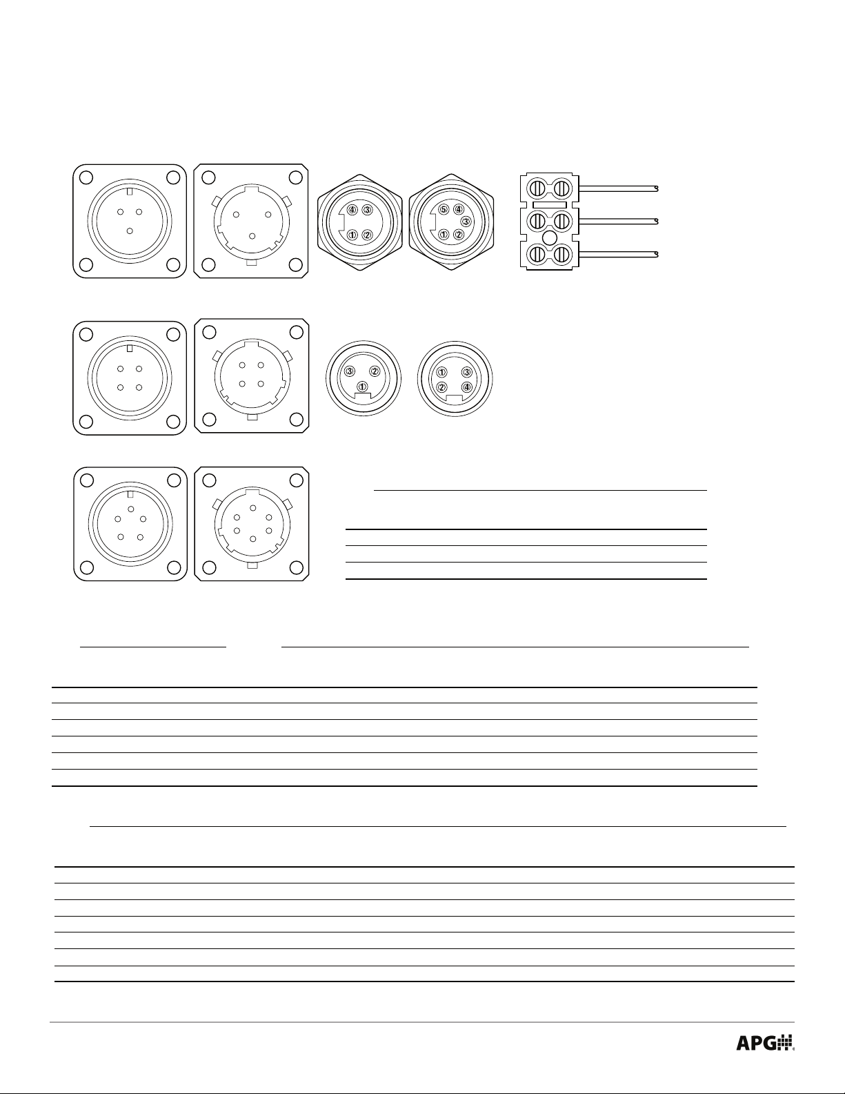
• Electrical Connectors and Pinout Table
4-20 mA Output Direct Wiring
Face view of male connector on HU
C A
B
3-Pin Threaded
MS3102
Connector
D
A
C
B
4-Pin Threaded
MS3102
Connector
A
E B
D C
5-Pin Threaded
MS3102
Connector
C A
B
3-Pin
Bayonet
Connector
D
A
C
B
4-Pin Reverse
Bayonet
Connector
A
FEB
C
D
6-Pin
Bayonet
Connector
4-Pin
Mini Style
Connector
Turk M12
RSFVL 36
Connector
5-Pin
Mini Style
Connector
Turk M12
P-RSFV 40-0.3
Connector
Flying Leads & Terminal Strip Wiring
E5 E10
Flying Lead Wires Junction Box (1502 only)
Wire 1/2” NPTM Coupling 1/2” NPTF Cable Entry
Red + Signal + Signal
Black – Signal – Signal
Yellow Shunt Cal Shunt Cal
+ Signal
– Signal
Shunt Cal
E17
Flying Lead Wires
1/2” NPTF Coupling
+ Signal
– Signal
Shunt Cal
Red Wire
Black Wire
Yellow Wire
0 to 5 VDC Output 4-20 mA Output
E3 E14 E1 E2 E6 E7 E8 E9
4 pin MS3102 6 pin Bayonet 4 pin Mini 5 pin Mini 3 pin M12 4 pin Bayonet 5 pin MS3102 3 pin MS3102
Pin Electroplate Nickel Stainless Steel Nickel Plated Zinc Nickel Plated Zinc Stainless Steel Stainless Steel Stainless Steel Stainless Steel
A (1) + Power + Power + Signal + Signal No Connection + Power/Signal No Connection No Connection
B (2) – Power + Signal – Signal – Signal + Power/Signal – Power/Signal – Power/Signal + Power/Signal
C (3) + Signal -Power Shunt Cal No Connection - Power/Signal Shunt Cal + Power/Signal - Power/Signal
D (4) – Signal – Signal No connection Shunt Cal – No Connection Shunt Cal –
E (5) – +Shunt Cal –
F – -Shunt Cal – – – – – –
Note: Mating connectors sold separately.
4-20 mA Output
E11 E13 E15 E18 E20 E28 E40
4 pin MS3102 7 Pin Jup./Souriau 6 pin Bayonet 4 pin ROTA 4 pin M12 6 pin Bayonet 3 pin Bayonet
Pin Stainless Steel Stainless Steel Stainless Steel Stainless Steel Stainless Steel Stainless Steel Stainless Steel
A (1) No Connection + Power/Signal + Power/Signal + Power/Signal -Power/Signal + Power/Signal + Power/Signal
B (2) – Power/Signal – Power/Signal – Power/Signal – Power/Signal + Power/Signal – Power/Signal – Power/Signal
C (3) + Power/Signal No Connection No Connection Case Ground No Connection No Connection Shunt Cal
D (4) Case Ground No Connection Case Ground Shunt Cal Case Ground No Connection –
E (5) – Shunt Cal + Shunt Cal – – No Connection –
F (6) – No Connection – Shunt Cal – – No Connection –
G (7) – No Connection – – – – –
Note: Mating connectors sold separately.
4
Tel: 1/888/525-7300 • Fax: 1/435/753-7490 • www.apgsensors.com • sales@apgsensors.com
No Connection
– – No Connection –
E45
6 pin Bayonet
Stainless Steel
+ Power/Signal
– Power/Signal
No Connection
Case Ground
Shunt Cal
No Connection
–
E49
6 pin Bayonet
Stainless Steel
+ Power/Signal
– Power/Signal
No Connection
No Connection
Shunt Cal
No Connection
–
Page 9
Chapter 2: Installation and Removal Procedures and Notes
• Tools Needed
You will need the following tools to install your HU1502I Hammer Union Pressure Transmitter:
• A hammer
• 1502 wing nut
DANGER: Mismatched unions and nuts can result in dangerous or hazardous equip-
ment failures. Always check identications on both union pieces and nuts prior to installation. Only use pieces with matching union gure numbers, sizes, and pressure ratings.
• Physical Installation
• Ensure mating union faces are clean, dry, and free of debris.
• Mate your Hammer Union Pressure Transmitter onto the socket.
• Place the wing nut on the Transmitter and spin into place.
• Hammer the wing nut until tight.
• Electrical Installation
• Check the pinout table on your Hammer Union Pressure Transmitter against your order.
• Check that your electrical system wiring matches the pinout table on your Hammer Union.
• For instruments with connectors, make the connection. Otherwise, connect the ying leads or junction
box to your electrical system.
IMPORTANT: To maintain the IP67/65 rating of your Hammer Union, you must use a
certied IP67/65 mating connector.
• Shunt Calibration Procedures
APG’s Hammer Union Pressure Transmitters can be congured with either a single-pin shunt calibration or
two-pin switched shunt calibration.
Tel: 1/888/525-7300 • Fax: 1/435/753-7490 • www.apgsensors.com • sales@apgsensors.com
5
Page 10

Single-Pin Shunt Calibration Procedure
APG’s Hammer Union Pressure Transmitters with single-pin shunt cal provide a full scale output (20.0 mA or
5 VDC) when 10 to 28 VDC is applied to the designated Shunt Cal pin. See the pinout chart on your Hammer
Union Pressure Transmitter’s label.
• Check the pinout table on your Hammer Union Pressure Transmitter.
• For 0 - 5 VDC Hammer Unions, connect +/- Power and +/- Signal, with a volt meter connected across
+/- Signal.
• For 4-20 mA Hammer Unions, connect +/- Signal, with - Signal connected through an Ammeter.
• Apply 10 to 28 VDC to the Shunt Cal pin.
• If the instrument electronics are opperating properly, the output signal will go to full scale (5 VDC or 20
mA).
Two-Pin Shunt Calibration Procedure
APG’s Hammer Union Pressure Transmitters with two-pin shunt cal provide a full scale output (20.0 mA or 5
VDC) when + Shunt is shunted to - Shunt. This is usually accomplised via an external switch. See the pinout
chart on your Hammer Union Pressure Transmitter’s label.
• Check the pinout table on your Hammer Union Pressure Transmitter.
• For 0 - 5 VDC Hammer Unions, connect +/- Power and +/- Signal, with a volt meter connected across +/-
Signal, and an open switch between + Shunt Cal and - Shunt Cal.
• For 4-20 mA Hammer Unions, connect +/- Signal, with - Signal connected through an Ammeter, and an
open switch between + Shunt Cal and - Shunt Cal.
• Close the open switch between + Shunt Cal and - Shunt Cal, ectively applying power to - Shunt Cal. (+
Power for 0 - 5 VDC, and + Signal for 4 - 20 mA, is tied to + Shunt Cal inside the Hammer Union)
• If the instrument electronics are opperating properly, the output signal will go to full scale (5 VDC or 20
mA) when the switch is closed.
• Removal Instructions
Removing your Hammer Union Pressure Transmitter from service must be done with care. It’s easy to create
an unsafe situation if you are not careful to follow these guidelines:
• Make sure the pressure is completely removed from the line where your sensor is installed. Follow any
and all procedures for safely isolating any media contained inside the line or vessel.
• Remove the Hammer Union wing nut.
• Remove your Pressure Transmitter.
• Clean the sensor’s tting and diaphragm of any debris (see above instructions) and inspect for damage.
• Store your sensor in a dry place, at a temperature between -40° F and 180° F.
DANGER: Removing your Hammer Union Pressure Transmitter while there is still
pressure in the line could result in injury or death.
6
Tel: 1/888/525-7300 • Fax: 1/435/753-7490 • www.apgsensors.com • sales@apgsensors.com
Page 11

Chapter 3: Maintenance
• General Care
Your Hammer Union Pressure Transmitter is designed to be maintenance free. As such, there are no
customer servicable parts on or in the device. However, in general, you should:
• Avoid touching the diaphragm. Contact with the diaphragm, especially with a tool, could permanently
shift the output and ruin accuracy.
• Clean the diaphragm or the diaphragm bore only with extreme care. If using a tool is required, make
sure it does not touch the diaphram.
• See Chapter 4 Recalibration Procedure for recalibration instructions.
• Repair and Returns
Should your Hammer Union Pressure Transmitter require service, please contact the factory via phone,
email, or online chat. We will issue you a Return Material Authorization (RMA) number with instructions.
• Phone: 888-525-7300
• Email: sales@apgsensors.com
• Online chat at www.apgsensors.com
Please have your Hammer Union Pressure Transmitter’s part number and serial number available. See
Waranty and Warranty Restrictions for more information.
IMPORTANT: All repairs and adjustments of the Recalibratable HU1502I Pressure
Transmitter must be made by the factory. Moding, disassembling, or altering the Recalibratable HU1502I Pressure Transmitter, other than factory approved recalibration, is
strictly prohibited.
Tel: 1/888/525-7300 • Fax: 1/435/753-7490 • www.apgsensors.com • sales@apgsensors.com
7
Page 12

Chapter 4: Recalibration Procedure
• Recalibration Wiring Diagrams
HU1502I
+Power/Signal
-Power/Signal
Calibration Port
HU1502I
+Power/Signal
-Power/Signal
VDC Source
+24 VDC
DC Ground
Ammeter
Current OUT
Current IN
Programming Module
USB connection
to computer
Figure 4.1
VDC Source
+24 VDC
DC Ground
Ammeter
Current OUT
Calibration Port
Programming Module
USB connection
to computer
Current IN
Figure 4.2
8
Tel: 1/888/525-7300 • Fax: 1/435/753-7490 • www.apgsensors.com • sales@apgsensors.com
Page 13

• Tools Needed
You will need the following tools to recalibrate your HU1502I Hammer Union Pressure Transmitter:
• A hammer
• 1502 wing nut
• Hex driver
• +24 VDC source
• Ammeter or voltmeter (per HU1502I output)
• Computer with USB port
• Hammer Union test station capable of applying calibrated full scale pressure to the HU1502I
• Recalibration Set Up - Computer
Prior to connecting your HU1502I Pressure Transmitter to the Programming Module:
• Install the Hammer Union Calibrator software on the computer to be used for recalibration.
Note: Contact the factory for the Hammer Union Calibrator software.
IMPORTANT: Hammer Union Calibrator software must be installed on a computer
with a USB port.
• Recalibration Set Up - HU1502I
Setting up your HU1502I Pressure Transmitter for recalibration must be done with care. It’s easy to create
an unsafe situation if you are not careful to follow these guidelines:
• Install the HU1502I in a test station capable of applying calibrated full scale pressure to the transducer.
Begin with 0 pressure applied to the HU1502I.
• Use a ratchet and Allen socket to remove the NPT plug covering the recalibration port.
• Connect the HU1502I to a 24 VDC source and an ammeter or voltmeter. Consult the pinout on the
HU1502I label and the wiring diagrams on page 8 (Figure 4.1 for 4-20 mA Output, Figure 4.2 for 0-5 VDC
output) to ensure correct pin/wire connections.
• Power on VDC Source and ammeter/voltmeter. The meter should show a reading at or near zero pressure (4 mA or 0 VDC) if everything is connected correctly.
• Plug 3.5mm on Programming Module into HU recalibration port.
Tel: 1/888/525-7300 • Fax: 1/435/753-7490 • www.apgsensors.com • sales@apgsensors.com
9
Page 14

• Software User Interface
Connect Button
Disconnect Button
Log File Open
Button
Settings Revert
Button
Zero Calibration Slider
Span Calibration Slider
Connection Status
Indicator
Zero Calibration Value
Zero Calibration Save Button
Button and Slider operations and Displays
Connect Button:
Initiates connection between Hammer Union Calibrator software and Recalibratable HU1502I.
Disconnect Button:
Ends connection between Hammer Union Calibrator software and Recalibratable HU1502I.
Log File Open Button:
Opens Log File txt. Every attempt to write a calibration value is logged as successful or unsucessful.
Settings Revert Button:
Clears UNSAVED calibration adjustments. Sliders will not reset, but ammeter/voltmeter will display
inital output value.
Zero Calibration Slider:
Adjusts zero output (4 mA/0 VDC). Can be adjusted with mouse or ↑ and ↓ buttons.
Zero Calibration Value:
Displays current calibration adjustment. Can be cleared via Settings Revert Button before clicking
Zero Calibration Save Button. CANNOT read current calibration value on Recalibratable HU1502I.
Span Calibration Value
Span Calibration Save Button
Figure 4.3
10
Tel: 1/888/525-7300 • Fax: 1/435/753-7490 • www.apgsensors.com • sales@apgsensors.com
Page 15

Zero Calibration Save Button:
Writes Zero Calibration Value to Recalibratable HU1502I.
Span Calibration Slider:
Adjusts full scale output (20 mA/5 VDC). Can be adjusted with mouse or ↑ and ↓ buttons.
Span Calibration Value:
Displays current calibration adjustment. Can be cleared via Settings Revert Button before clicking
Span Calibration Save Button.
Span Calibration Save Button:
Writes Span Calibration Value to Recalibratable HU1502I.
Connection Status Indicator:
Displays current status of connection between Hammer Union Recalibrator software and Recalibratable HU1502I, and success or failure of write attempts to Recalibratable HU1502I (See Figure 4.5).
• Recalibration Procedure
After completing the set up instructions above, follow the these steps to recalibrate your HU1502I:
1. Connect programming unit to computer with Hammer Union Calibrator software already installed via
USB port.
2. Launch Hammer Union Calibrator software.
3. Click Connect Button (See Figure 4.3) to initiate connection between Hammer Union Calibrator software and HU1502I. Wait for Connection Status Indicator to read “Open Successful” (See Figure 4.4).
4A. With 0 pressure applied to the HU1502I, adjust Zero Calibration Slider (See Figure 4.3) until ammeter
reads 4 mA or voltmeter reads 0 VDC, to the desired precision. Allow 1 second for ammeter/voltmeter
reading to stabilize after adjusting slider.
4B. When desired reading shows on ammeter/voltmeter, press Zero Calibration Save Button.
5A. Apply full scale pressure to HU1502I.
5B. Adjust Span Calibration Slider until ammeter reads 20 mA or voltmeter reads 5 VDC. Allow 1 second
for ammeter/voltmeter reading to stabilize after adjusting slider.
5C. When desired reading shows on ammeter/voltmeter, press Span Calibration Save Button.
5D. Release pressure applied to HU1502I.
6. Repeat Steps 4A - 5D as necessary (usually two or three iterations) until Zero and Span readings are
calibrated to desired precision.
7. To reinstall 1/8” plug in recalibration port, wrap the plug with 3 wraps of PTFE tape. Tighten the plug to
1 full turn past hand-tight using an Allen socket and ratchet.
IMPORTANT: Zero Calibration Value and Span Calibration Value are not written unless
the corresponding Save Button is clicked.
Note: Any adjustments made can be discarded BEFORE clicking a Calibration Save
Button by clicking the Settings Revert Button (See Figure 4.3). Slider position and value will
not reset, but ammeter/voltmeter reading will reset to value prior to slider adjustment.
Tel: 1/888/525-7300 • Fax: 1/435/753-7490 • www.apgsensors.com • sales@apgsensors.com
11
Page 16

Figure 4.4
12
Figure 4.5
Tel: 1/888/525-7300 • Fax: 1/435/753-7490 • www.apgsensors.com • sales@apgsensors.com
Page 17

Chapter 5: Hazardous Location Installation and Certication
• Intrinsically Safe Wiring Diagram
D
REV
APPROVED
DATE
REVISIONS
DESCRIPTION
SEE CHANGE ORDER.
D
REV
--
ZONE
HAZARDOUS AREA
888.525.7300
Logan, Utah USA
1025 West 1700 North
ACTUAL PINOUT PER LABEL ON UNIT.
SUBSTITUTION OF COMPONENTS
MAY IMPAIR INTRINSIC SAFETY.
HAZARDOUS AREA
UNION PRESSURE TRANSMITTER
INSTALLATION DRAWING HAMMER
CSA INTRINSICALLY SAFE HAZARDOUS
AUTOMATION PRODUCTS GROUP, INC.
DATE
R. OBORN
E. TOLMAN
M. HARVEY
APPROVALS
APVD
CHKD
DRWN
1
.01
.005
PER ASME Y14.5-2009
UNLESS OTHERWISE SPECIFIED
2 PLACES:
3 PLACES:
DIMENSIONS ARE IN INCHES
AND TOLERANCES ARE AS FOLLOWS:
TOLERANCE ON ANGLES:
INTERPRET DIMENSIONS AND TOLERANCES
1 OF 1
DOCUMENT NO
SHEET
PER ORDER
PART NO
52797
CAGE CODE
1:1
C
SIZE
SCALE
FINISH
MATL
CONTRACT
THIRD ANGLE PROJECTION
NON-HAZARDOUS AREA
INSTALLED IN ACCORDANCE WITH
THIS DEVICE MUST BE CONNECTED TO AN
BARRIERS MUST BE NRTL APPROVED AND MUST BE
1.
2.
-
-
-
-
Tel: 1/888/525-7300 • Fax: 1/435/753-7490 • www.apgsensors.com • sales@apgsensors.com
DISCLOSED TO OTHERS WITHOUT
LOGAN, UTAH AND MAY NOT BE
PROPRIETARY AND CONFIDENTIAL
THIS DRAWING IS THE PROPERTY OF
AUTOMATION PRODUCTS GROUP, INC.
DETRIMENTAL TO THE COMPANY.
IF LOANED, IT IS SUBJECT TO RETURN
USED, REPRODUCED, PUBLISHED, OR
IN ANY WAY DIRECTLY OR INDIRECTLY
WRITTEN CONSENT OF THE COMPANY.
UPON DEMAND AND MAY NOT BE USED
NON-HAZARDOUS AREA
APPROVED SAFETY BARRIER.
BARRIER PARAMETERS MUST MEET THE FOLLOWING
A.
B.
C.
INSTALL IN ACCORDANCE WITH THE NEC
3.
4.
5.
MATING CONNECTOR.
DO NOT ALTER WITHOUT PROPER APPROVAL
FROM THE CONTROLLING AGENCY
AUTHORIZED PERSON AND THE NOTIFIED BODY.
13
Page 18

• CSA Certicate of Compliance
Certificate of Compliance
Certificate: 1916494 Master Contract: 237484 (237484)
Project: 70177689 Date Issued: 2018-06-26
Issued to: Automation Products Group Inc
1025 West 1700 North
Logan, Utah 84321
USA
Attention: Joseph James
The products listed below are eligible to bear the CSA Mark shown
with adjacent indicators 'C' and 'US' for Canada and US or with adjacent
indicator 'US' for US only or without either indicator for Canada only.
Issued by:
PRODUCTS
CLASS 2258 04 - PROCESS CONTROL EQUIPMENT - Intrinsically Safe, Entity - For Hazardous Locations
CLASS 2258 84 - PROCESS CONTROL EQUIPMENT - Intrinsically Safe, Entity - For Hazardous Locations -
To U.S. Requirements
Class I, Division 1, Groups C, D
Class I, Zone 0
Ex ia IIB T4
AEx ia IIB T4
Hammer Union Pressure Sensor, Model HU-Ln-IS, HU-1502SS-Ln, and HU1502I-Ln (where Ln = L1,
L3, L24 or L27). Temperature Code Rating T4; Ambient range -40°C to +85°C; Enclosure Type: IP65
and IP67; Maximum Working Pressure: 20,000 PSI; Installed as per Drawing 9002460; Intrinsically Safe
with the following Entity Parameters:
Vmax, Ui = 28Vdc
Imax, Ii = 110mA
Pmax, Pi = 1W
Ci = 60.89nF
Li = 7.7mH
DQD 507 Rev. 2016-02-18 Reaffirmed 2018-04-09 Page 1
Albert Jansen
Albert Jansen
14
Tel: 1/888/525-7300 • Fax: 1/435/753-7490 • www.apgsensors.com • sales@apgsensors.com
Page 19

Certificate:
Project:
1916494
70177689
Master Contract: 237484
Date Issued: 2018-06-26
Conditions of Acceptability
To maintain IP67/65 rating, the equipment shall be installed with a certified IP67/65 mating connector.
This device must be connected to a NRTL approved safety barrier
Note: Suffixes are added to indicate options not affecting safety.
APPLICABLE REQUIREMENTS
CAN/CSA-C22.2 No. 0-10 (R2015) General Requirements – Canadian Electrical Code, Part II
CAN/CSA-C22.2 No. 60950-1-07 Information technology Equipment – Safety – Part1: General Requirements
CAN/CSA-C22.2 No. 60079-0:15 Explosive Atmosp heres - Part 0: Equipment - General requirements
CAN/CSA-C22.2 No. 60079-11:14 Explosive Atmospheres – Part 11: Equipment protection by intrinsic safety "i"
UL 60950-1 Edition 2 Information technology Equipment – Safety – Part1: General Requirements
ANSI/UL 60079-0:13 Electrical Apparatus for Explosive Gas Atmospheres - Part 0: General Requirements
ANSI/UL 60079-11:13 Electrical apparatus for Explosive Gas Atmospheres - Part 11: Intrinsic Safety “i”
DQD 507 Rev. 2016-02-18 Page 2
Tel: 1/888/525-7300 • Fax: 1/435/753-7490 • www.apgsensors.com • sales@apgsensors.com
15
Page 20

Certificate:
Project:
1916494
70177689
Master Contract: 237484
Date Issued: 2018-06-26
MARKINGS
The manufacturer is required to apply the following markings:
Products shall be marked with the markings specified by the particular product standard.
Products certified for Canada shall have all Caution and Warning markings in both English and French.
Additional bilingual markings not covered by the product standard(s) may be required by the Authorities Having
Jurisdiction. It is the responsibility of the manufacturer to provide and apply these additional markings, where
applicable, in accordance with the requirements of those authorities.
The products listed are eligible to bear the CSA Mark shown with adjacent indicators 'C' and 'US' for Canada and
US (indicating that products have been manufactured to the requirements of both Canadian and U.S. Standards) or
with adjacent indicator 'US' for US only or without either indicator for Canada only.
(1) Submittor's name, trademark, or the CSA file number (adjacent the CSA Mark).
(2) Catalogue / Model designation.
(3) Entity Parameters
(4) Date code / Serial number traceable to month and year of manufacture.
(5) Hazardous Location designations.
(6) The words "Exia, INTRINSICALLY SAFE".
(7) Temperature code T4.
(8) Ambient -40°C to +85°C
(9) Maximum working pressure.
(10) Enclosure Type: IP 65/67
(11) The CSA Mark with the c and us qualifiers as applicable.
The products listed above are eligible to bear the CSA Mark with adjacent indicators “C” and “US” for Canada
and US or with adjacent indicator “US” for US only or without either indicator for Canada only.
16
DQD 507 Rev. 2016-02-18 Page 3
Tel: 1/888/525-7300 • Fax: 1/435/753-7490 • www.apgsensors.com • sales@apgsensors.com
Page 21

Certificate:
Project:
Project
Date Description
70177689
2018
Update CSA Report 1916494 to add two new housing designs, specified as
HU
UL/CSA 61010-1.
2703264
2014-09-15
Update to Report 1916494 to revise input filter board.
2615564
2013-04-02
Update to include revised drawings with minor changes.
2517307
2012
Update to include a new EMI board within the Hammer Union Pressure
Sensor as well an IP65/67 certification for the sensor enclosure.
1916494
2007
Supersedes report 1854327 (sub report 1726089) to change listing to show
Ex ia and AEx ia.
1916494
70177689
Master Contract: 237484
Date Issued: 2018-06-26
Supplement to Certificate of Compliance
Certificate: 1916494 Master Contract: 237484 (237484)
The products listed, including the latest revision described below,
are eligible to be marked in accordance with the referenced Certificate.
Product Certification History
-06-26
-1502I and HU-1502SS. Upgrade all models from CSA 142-M1987 to
-08-09
-05-30
DQD 507 Rev. 2016-02-18 Page 4
Tel: 1/888/525-7300 • Fax: 1/435/753-7490 • www.apgsensors.com • sales@apgsensors.com
17
Page 22

• EU Declaration of Conformity
18
Tel: 1/888/525-7300 • Fax: 1/435/753-7490 • www.apgsensors.com • sales@apgsensors.com
Page 23

4
• IECEx Certicate of Conformity
INTERNATIONAL ELECTROTECHNICAL COMMISSION
IEC Certification Scheme for Explosive Atmospheres
for rules and details of the IECEx Scheme visit www.iecex.com
IECEx Certificate
of Conformity
Certificate No.: IECEx CSA 13.0004X Issue No: 2 Certificate history:
Status: Current
Date of Issue: 2018-07-20
Applicant: Automation Products Group, Inc.
Equipment: 4-20mA Pressure Transmitter (HU-L24, HU-1502SS, and HU-1502I)
Optional accessory:
Type of Protection: Ex ia
Marking:
Approved for issue on behalf of the IECEx
Certification Body:
Position:
Signature:
(for printed version)
Date:
1025 W 1700 N Logan
Utah, 84321
United States of America
Ex ia IIB T4 Ga
Ta: -40°C to +85 °C
Dorin Stochitoiu
Technical Advisor
Page 1 of
Issue No. 2 (2018-07-20)
Issue No. 1 (2014-10-17)
Issue No. 0 (2013-03-08)
1. This certificate and schedule may only be reproduced in full.
2. This certificate is not transferable and remains the property of the issuing body.
3. The Status and authenticity of this certificate may be verified by visiting the Official IECEx Website.
Certificate issued by:
CSA International
178 Rexdale Boulevard
Toronto, Ontario M9W IR3
Canada
Tel: 1/888/525-7300 • Fax: 1/435/753-7490 • www.apgsensors.com • sales@apgsensors.com
19
Page 24

IECEx Certificate
4
of Conformity
Certificate No: IECEx CSA 13.0004X Issue No: 2
Date of Issue: 2018-07-20
Manufacturer: Automation Products Group, Inc.
Additional Manufacturing location(s):
This certificate is issued as verification that a sample(s), representative of production, was assessed and tested and found to comply with the
IEC Standard list below and that the manufacturer's quality system, relating to the Ex products covered by this certificate, was assessed and
found to comply with the IECEx Quality system requirements. This certificate is granted subject to the conditions as set out in IECEx Scheme
Rules, IECEx 02 and Operational Documents as amended.
STANDARDS:
The apparatus and any acceptable variations to it specified in the schedule of this certificate and the identified documents, was found to comply
with the following standards:
IEC 60079-0 : 2011
Edition:6.0
IEC 60079-11 : 2011
Edition:6.0
This Certificate does not indicate compliance with electrical safety and performance requirements other than those expressly included in the
TEST & ASSESSMENT REPORTS:
A sample(s) of the equipment listed has successfully met the examination and test requirements as recorded in
1025 W 1700 N Logan
Utah, 84321
United States of America
Explosive atmospheres - Part 0: General requirements
Explosive atmospheres - Part 11: Equipment protection by intrinsic safety "i"
Standards listed above.
Page 2 of
20
Test Report:
CA/CSA/ExTR13.0004/00 CA/CSA/ExTR13.0004/01 CA/CSA/ExTR13.0004/02
Quality Assessment Report:
NL/DEK/QAR13.0027/03
Tel: 1/888/525-7300 • Fax: 1/435/753-7490 • www.apgsensors.com • sales@apgsensors.com
Page 25

IECEx Certificate
4
of Conformity
Certificate No: IECEx CSA 13.0004X Issue No: 2
Date of Issue: 2018-07-20
Schedule
EQUIPMENT:
Equipment and systems covered by this certificate are as follows:
The HU-L24-IS-nnK-PSIS-Enn-Pnn-Knn-Bnn, HU-1502SS-Ln, and HU-1502I-Ln 4-20mA Pressure Transmitters consists of encapsulated
electronics on two, separate printed circuit boards which connects to a silicon resistive strain gage arranged in a Wheatstone bridge
configuration mounted in a two-part housing. The upper half of the housing has one of the two printed circuit boards, dedicated for EMI
protection. The bottom half of the two part housing is comprised of the second printed circuit board (main electronics) and the strain gage
element which are mounted on a thin walled section of the enclosure. The strain gage connects to the main board in the lower housing via a
ribbon cable. There is no direct process connection between the pressure sensor and the external environment being measured. External
electrical connections are made to the connector fitted at one end.
The equipment has the following safety description (Entity Parameters):
Ui = 28V, Ii = 110mA, Pi = 1W, Ci = 60.89nF, Li = 7.7mH
SPECIFIC CONDITIONS OF USE: YES as shown below:
●
To maintain IP67/65 rating, the equipment shall be installed with a certified IP67/65 mating connector.
●
This device must be connected to an approved safety barrier (located in a safe area).
Page 3 of
Tel: 1/888/525-7300 • Fax: 1/435/753-7490 • www.apgsensors.com • sales@apgsensors.com
21
Page 26

IECEx Certificate
4
of Conformity
Certificate No: IECEx CSA 13.0004X Issue No: 2
Date of Issue: 2018-07-20
DETAILS OF CERTIFICATE CHANGES (for issues 1 and above):
Issue 1:The change involves modification of the EMI board to add a common mode choke and protective circuitry to better protect the
Hammer Union sensor against surges and fast transients. The Li parameter has been modified as a result. The customer also lowered the Ui
value.
Issue 2:The change involves the addition of two new models, which are enclosure variants of the existing model. These two new models are
denoted as the HU-1502SS and the HU-1502I. No electrical changes.
Page 4 of
22
Tel: 1/888/525-7300 • Fax: 1/435/753-7490 • www.apgsensors.com • sales@apgsensors.com
Page 27

Tel: 1/888/525-7300 • Fax: 1/435/753-7490 • www.apgsensors.com • sales@apgsensors.com
23
Page 28

APG
R
Tel: 1/888/525-7300 • Fax: 1/435/753-7490 • www.apgsensors.com • sales@apgsensors.com
Automation Products Group, Inc.
 Loading...