


 Loading...
Apex EL-80DTF, EL-80DT, EL-480DT, EL-80DC, EL-280DT User Manual
...User Guide
EL-40DT / EL-80DT / EL-80DTF |
EL-80DC |
|
|
|
|
|
|
|
|
|
|
|
|
|
EL-280DT / EL-480DT |
EL-100DT |
Innovation & Technology by Design
APEX™
PC SOLUTIONS
OutLook User Guide
© 1998 Apex PC Solutions, Inc. All rights reserved. Fourth Edition August 1998
Printed in the United States of America
Apex Part Number 053-0074-00
The information in this guide is subject to change without notice.
Apex PC Solutions shall not be liable for technical or editorial errors or omissions contained herein; nor is it liable for incidental or consequential damages resulting from the furnishing, performance, or use of this material.
Product names mentioned herein may be trademarks and/or registered trademarks of their respective companies. PC/AT, PS/2, RS/6000 and IBM are registered trademarks of International Business Machines Corporation. Sun Microsystems and Sun Sparc are registered trademarks of Sun Microsystems, Inc. OutLook and OSCAR are registered trademarks and the Apex logo is a trademark of Apex PC Solutions, Inc. in the United States and other countries. Various aspects of OutLook and its OSCAR interface are protected by United States patent number 5721842.
Apex PC Solutions Inc
20031 142nd Ave NE
Woodinville WA 98072
USA
Tel |
425 402-9393 |
Fax |
425 402-9494 |
info@apexpc.com |
|
Web |
http://www.apexpc.com |
2

Technical Support
Along with your OutLook switch, you receive a variety of support services to give you the results you need quickly and professionally.
Where to go for assistance
Visit our web site for the latest technical information and to download upgrades www.apexpc.com
Contact your distributor or reseller
E-mail Apex Technical Support service@apexpc.com
Phone Apex Technical Support Monday through Friday between 7 am and 6 pm Pacific Time 800 861-5858
What information you need to provide to Apex Technical Support
Unit model number and serial number.
Make and model of keyboard and mouse attached to the unit. These numbers are on the underside of each unit.
Make and model of computers used.
Name and version of operating systems used.
3

Communications Regulation Information
ENGLISH
Federal Communications Notice (Class A Equipment)
This equipment has been tested and found to comply with the limits for a Class A digital device, pursuant to Part 15 of the FCC rules. These limits are designed to provide reasonable interference when the equipment is operated in a commercial environment.
Radio Interference
This equipment generates, uses, and can radiate radio frequency energy and, if not installed and used in accordance with the instructions, may cause harmful interference to radio communications. Operation of this equipment in a residential area is likely to cause harmful interference, in which case the user will be required to correct the interference at personal expense.
DOC Class A Compliance
This digital apparatus does not exceed the Class A limits for radio noise emissions from digital apparatus as set out in the interference-causing equipment standard entitled “Digital Apparatus,” ICES-003 of the Department of Communications.
FRANÇAIS
Observation des normes—Classe A
Cet appariel numérique respecte les limites de bruits radioélectriques applicables aux appariels numérique de Classe A prescrites dans la norme sur le matériel brouilleur: “Appariels Numérique,” NMB-003 édictée par le ministre des Communications.
DEUTSCH
BZT Hinweis
Hiermit wird bescheinigt, daß dieses Gerät in Übereinstimmung mit den Bestimmugen der BMPT-AmtsblVfg 243/1991 funk-entstört ist. Der vorschriftsmäßige Betrieb mancher Gerät (z.B. Meßsender) kann allerdings gewissen Einschränkungen unterliegen. Beachten Sie deshalb die Hinweise in der Bedienungsanleitung.
Dem Bundesamt für Zulassungen in der Telekommunikation wurde das Inverkehrbringen dieses Geräts angezeigt und die Berechtigung zur Überprüfung der Serie auf die Einhaltung der Bestimmugen eingeräumt.
4
Limited Warranty
Apex PC Solutions warrants that the Outlook Switch (Product) will be free from defects in materials and workmanship under normal use and service for a period of one year from the date of receipt. Any implied warranty on the switch is limited to one year.
Customer Remedies
Apex PC Solutions’ entire liability and your exclusive remedy shall be, at Apex’s option, either (a) return of the price paid or (b) repair or replacement of the Product that does not meet Apex’s Limited Warranty and which is returned to Apex with a copy of your receipt. THIS LIMITED WARRANTY IS VOID IF FAILURE OF THE PRODUCT HAS RESULTED FROM ACCIDENT, ABUSE, OR MISAPPLICATION. Any replacement Product will be warranted for the remainder of the original warranty period or six months, whichever is longer.
No Other Warranties
APEX PC SOLUTIONS DISCLAIMS ALL OTHER WARRANTIES, EITHER EXPRESSED OR IMPLIED, INCLUDING BUT NOT LIMITED TO IMPLIED WARRANTIES OF MERCHANTABILITY AND FITNESS FOR A PARTICULAR PURPOSE, WITH RESPECT TO THE PRODUCT AND THE ACCOMPANYING PRODUCT MANUAL AND WRITTEN MATERIALS.
This Limited Warranty gives you specific rights, and you may have other rights which vary from state to state.
No Liability For Consequential Damages
IN NO EVENT SHALL APEX PC SOLUTIONS BE LIABLE FOR ANY OTHER DAMAGES WHATSOEVER (INCLUDING, WITHOUT LIMITATION, DAMAGES FOR LOSS OF BUSINESS PROFITS, BUSINESS INTERRUPTION, LOSS OF BUSINESS INFORMATION, OR OTHER PECUNIARY LOSS) ARISING OUT OF THE USE OF OR INABILITY TO USE THE PRODUCT, EVEN IF APEX PC SOLUTIONS HAS BEEN ADVISED OF THE POSSIBILITY OF SUCH DAMAGES. IN ANY CASE, APEX PC SOLUTIONS’ ENTIRE LIABILITY UNDER ANY PROVISION OF THIS AGREEMENT SHALL BE LIMITED TO THE AMOUNT ACTUALLY PAID BY YOU FOR THE PRODUCT.
5
A P E X O U T L O O K S W I T C H E S
CONTENTS
1 INTRODUCTION . . . . . . . . . . . . . . . . . . . . . . . . |
9 |
Overview . . . . . . . . . . . . . . . . . . . . . . . . . . . . 9
Features . . . . . . . . . . . . . . . . . . . . . . . . . . . . . 10
Illustrations of Switch Systems . . . . . . . . . . . . 11
Model Comparison Chart . . . . . . . . . . . . . . . . 13
2 INSTALLATION . . . . . . . . . . . . . . . . . . . . . . . . . |
15 |
Installation Check List . . . . . . . . . . . . . . . . . . 15
Your OutLook switch package contains . . . . 15
You need to provide . . . . . . . . . . . . . . . . . . 15
Save your OutLook switch package . . . . . . . 15
Select switch connection mode for
EL-280DT/EL-480DT . . . . . . . . . . . . . . . . . 16
Select location for the
OutLook switch . . . . . . . . . . . . . . . . . . . . . 16
Connecting the Console . . . . . . . . . . . . . . . . . 17
Standard connection . . . . . . . . . . . . . . . . . 17
Special connections . . . . . . . . . . . . . . . . . . 17
Remote connection . . . . . . . . . . . . . . . . . . . 17
Sequence of cable connection . . . . . . . . . . . 18
Connecting the Primary Switch to a
Secondary Switch (Tiering). . . . . . . . . . . . . . . 21 Tiered configurations . . . . . . . . . . . . . . . . . 21
Adding a secondary switch while
the system is running . . . . . . . . . . . . . . . . . 21 Port numbering scheme . . . . . . . . . . . . . . . 21
Connecting the Computers . . . . . . . . . . . . . . . 26
Adding a computer while
the system is running . . . . . . . . . . . . . . . . . 26
Turning On the System . . . . . . . . . . . . . . . . . . 30
Startup sequence . . . . . . . . . . . . . . . . . . . . 30
Startup behavior . . . . . . . . . . . . . . . . . . . . 30
6
3 OPERATION GUIDE . . . . . . . . . . . . . . . . . . . . . . 33
Navigating with OSCAR . . . . . . . . . . . . . . . . . 33
Operate with keyboard
and mouse . . . . . . . . . . . . . . . . . . . . . . . . . 33 Using the Print Screen key . . . . . . . . . . . . . 35 OSCAR Selection screen . . . . . . . . . . . . . . . 35 OSCAR Advanced Menus screen . . . . . . . . . 37
Selecting Computers . . . . . . . . . . . . . . . . . . . . 38
Assigning Unique Names to Computers . . . . . 39
Changing Menu Attributes . . . . . . . . . . . . . . . 40
Changing Status Flag Attributes . . . . . . . . . . . 42
Scanning the Computers . . . . . . . . . . . . . . . . . 44
Broadcasting Commands . . . . . . . . . . . . . . . . 46
Broadcasting to tiered configurations . . . . . 47
Securing Server Access . . . . . . . . . . . . . . . . . . 50
Displaying Version Information . . . . . . . . . . . . 52
Saving the Hardware Settings . . . . . . . . . . . . . 53
Resetting the Mouse and Keyboard . . . . . . . . . 54
Assigning Specific Device Types . . . . . . . . . . . 55
Adjusting the Video Impedance Value . . . . . . . |
56 |
|
|
Your video board version . . . . . . . . . . . . . . |
56 |
|
Impedance values in tiered systems . . . . . . |
57 |
APPENDICES . . . . . . . . . . . . . . . . . . . . . . . . . . . |
59 |
|
A |
Specifications . . . . . . . . . . . . . . . . . . . . . . |
60 |
B |
Options and Accessories . . . . . . . . . . . . . . |
61 |
C |
Troubleshooting . . . . . . . . . . . . . . . . . . . . |
62 |
D |
Firmware Upgrade Instructions. . . . . . . . . |
64 |
E |
Connector Pin Specifications . . . . . . . . . . |
66 |
F |
Optional Rackmounting . . . . . . . . . . . . . . |
67 |
G |
Setting OutLook DIP Switches . . . . . . . . . |
68 |
7
8

INTRODUCTION1
OVERVIEW
Apex PC Solutions offers the OutLook® family of switches to enable you to control large computer networks using a single keyboard, monitor, and mouse. On a single video screen, you can select as many as 100 computers running different operating systems. The OutLook switch patented On-Screen Configuration and Activity Reporting (OSCAR) interface has intuitive menus for accessing each attached computer. Computers can be identified by name or number, enabling you to view and select server names that make sense to you.
A typical OutLook switch system consists of the console (monitor, keyboard, and mouse), the switch unit, and the attached computers. You can choose from a single-user system or a multiple-user system. The OutLook family includes switches specifically designed for use in telecommunications systems, financial and trading applications, and Sun/Unix networks. Additional OutLook switches can be connected to the primary OutLook switch, called tiering, to increase computer access from 4, 8, or 10 computers
A P E X O U T L O O K S W I T C H E S
Overview
Features
Illustrations of Switch Systems
Model Comparison Chart
to as many as 16, 64, or 100 computers. Tiering allows you to modify your OutLook switch system, as your network system needs change.
Switching between computers is accomplished by typing a command at the keyboard. The selected computer receives characters typed at the keyboard and displays its video output on the monitor. You can also use the mouse to interact with the graphic interface of the selected computer.
The OutLook family of products is available in 4, 8, and 10-port versions and can be used in various configurations to accommodate large or small systems. All versions are packaged in space-efficient 1-U height (1.75-in) or 2-U (3.5-in) cases for desktop or rack-mounted systems.
Overview
9

Features
1 Introduction
FEATURES
Compatible with major computer and peripheral devices, including:
•Industry standard PS/2 mouse and keyboard
•RS/6000 keyboard and mouse
•Computers requiring serial pointing devices
(Via the Apex PS/2-to-serial port converter)
•Sun Microsystems workstations
Offers customization and adaptability to network needs
•Flexible configurations for a variety of networks
•Adapts easily to changing network needs
•Integrates computers running diffferent operating systems
Support standard display converters and high-resolution video, specifically:
•Analog VGA, SVGA, and XGA video
•Maximum resolution of 1024 x 768 for video with a 25-ft video cable, except for EL-100DT which has a maximum resolution of 1600 x1200 with a 12-ft video cable.
•Sun, RS/6000, HP 9000, and Apple Macintosh video (using converters purchased separately).
Ease of Use and Maintenance
•On-Screen Configuration and Activity Reporting (OSCAR) OSCAR displays system-related information on the monitor, including power-up test data and configuration menus.
•Programmable scanning
Lets you observe system default performance by automatically switching computers in sequence, or you can set the sequence and duration for each computer in the system.
•Nonvolatile memory Stores system settings and
display options even if the unit is turned off or unplugged.
•External reset switch Reinitializes attached devices without interrupting power to the system
•External keypad
Can take the place of the keyboard for switching between computers.
•Password security feature Protects network resources by locking the keyboard and monitor.
10

A P E X O U T L O O K S W I T C H E S
ILLUSTRATIONS OF SWITCH SYSTEMS
Single-Switch Systems
Single-user units connecting 4 or 8 computers. Access up to 64 computers in tiered configurations.
EL-40DT and EL-80DT
Multiple-user units allowing 2 or 4 users to select up to 8 computers. Access up to 64 computers in tiered configurations.
EL-280DT and EL-480DT
Systems Switch of Illustrations
|
|
|
|
|
|
|
|
|
|
|
|
|
|
|
|
|
|
|
|
|
|
|
|
|
|
|
|
|
|
|
|
|
|
|
|
|
|
|
|
|
|
|
|
|
|
|
|
|
|
|
|
|
|
|
|
|
|
|
|
|
|
|
|
|
|
|
|
|
|
|
|
|
|
|
|
|
|
|
|
|
|
|
|
|
|
|
|
|
|
|
|
|
|
|
|
|
|
|
|
|
|
|
|
|
|
|
|
|
|
|
|
|
|
|
|
|
|
|
|
|
|
|
|
|
|
|
|
|
|
|
|
|
|
|
|
|
|
|
|
|
|
|
|
|
|
|
|
|
|
|
|
|
|
|
|
|
|
|
|
EL-80DFT |
EL-100DT |
||||||||||||||||||
|
|
|
|
|
|
|
|
|
|
|
|
|
|
|
|
|
|
|
|
Single-user unit connecting 8 computers with only keyboard and mouse switching. Designed for financial and trading applications.
Single-user unit connecting up to 10 computers. Access up to 100 Sun computers in tiered configurations. Designed for SunUnix networks.
11

1 Introduction
Multiple-Switch or Tiered System
This sample tiered configuration shows the EL-80DT switch connected to two secondary EL-80DT switches.
Illustrations of Switch Systems
12

A P E X O U T L O O K S W I T C H E S
MODEL COMPARISON CHART
Model Comparison Chart
EL-40DT |
EL-80DT |
EL-80DTF |
EL-100DT |
EL-80DC |
EL-280DT |
EL-480DT |
Number of computer ports |
|
|
|
|
|
|
4 |
8 |
8 |
10 |
8 |
8 |
8 |
Number of consoles (monitor, keyboard, mouse) |
|
|
|
|||
1 |
1 |
K & M |
1 |
1 |
2 |
4 |
|
|
only |
|
|
|
|
Number of tiered computers |
|
|
|
|
|
|
32 |
64 |
64 |
100 |
64 |
64 |
64 |
Switches keyboard, video, mouse |
|
|
|
|
||
yes |
yes |
K & M |
yes |
yes |
yes |
yes |
|
|
only |
|
|
|
|
Switch connection mode control |
|
|
|
|
||
no |
no |
no |
no |
no |
yes |
yes |
Specific system environment |
|
|
|
|
|
|
no |
no |
Financial |
SunUnix |
Telecom |
no |
no |
|
|
& trading |
|
systems |
|
|
Power supply |
|
|
|
|
|
|
110/220V AC |
110/220V AC |
110/220V AC |
110/220V AC |
48V DC |
110/220V AC |
110/220V AC |
|
|
|
|
|
|
|
13

1 Introduction
14

|
A P E X O U T L O O K S W I T C H E S |
INSTALLATION |
Installation Checklist |
|
|
2 |
Connecting the Console |
|
|
Connecting the Primary Switch to a |
|
Secondary Switch (Tiering) |
|
|
|
Connecting the Computers |
|
|
Turning On the System |
|
|
INSTALLATION CHECK LIST
Your OutLook switch package contains
•The OutLook switch main unit
•Its power cord
(not included with EL-80DC)
•This User Guide
•A warranty card
You need to provide
•Interconnecting cables for video, keyboard, and mouse
Interconnecting and extension cables may be purchased separately from Apex.(see
Appendix B Options and Accessories)
•Your monitor, keyboard, and mouse for each user console
•Your computers
Save your OutLook switch package
Apex ships the OutLook switch in packaging designed to protect the system during shipping and handling. We recommend that you save the carton and packing materials until your equipment is fully installed and operational.
If you should find that anything is missing or arrived damaged, please contact Apex PC Technical Support. If you do need to return the product, you must get an authorization number from technical support. Apex PC Solutions will not accept any returned materials without first issuing a return materials authorization number.
Checklist Installation
15

Installation Checklist
2 Installation
Select switch connection mode for EL-280DT/EL-480DT
If you have purchased the multiple user system EL-280DT or EL-480DT, you must choose which switch connection mode you perfer, either cooperative or preemptive. Both models ship with the factorydefault “cooperative” switch connection mode. Cooperative switching maintains established port connections. If another console attempts to select that port, the request is denied. If you want to change the default setting to have the switch favor new connections, you need to move the DIP switch 1 to the “preemptive” setting. For additional information and instructions, see Appendix G,
Setting DIP Switches.
Select location for the OutLook switch
OutLook switches can be used in desktop or rackmounted systems. Rackmount kits are available from Apex PC Solutions if you would like to mount your switch in an EIA-standard 19-inch equipment rack. Contact your Apex sales representative for more information regarding rackmount kits for specific computers. See Appendix F for instructions for mounting brackets that fit EIA-standard equipment racks.
Maximum Cable Length Distance for Components
12 ft |
console to switch |
50 ft |
computer to switch |
50 ft |
switch to switch |
|
|
Cable length affects video quality as well as keyboard and mouse data timing. The maximum length is determined in part by the computer and peripherals used. Not all systems will give satisfactory results at the maximum length.
16

A P E X O U T L O O K S W I T C H E S
CONNECTING THE CONSOLE
Standard connection
The console consists of the keyboard, mouse or other pointing device, and the monitor. The keyboard and mouse connections on the back panel of the switch are 6-pin mini-DIN PS/2 style. The video connection is HD15-pin VGA/SVGA style. If the cables on your keyboard, mouse, or monitor require different connectors, you can obtain a converter from Apex (see Appendix B Options and Accessories) or from the manufacturer of the device.
Special connections
The EL-100DT OutLook switch
You will need a video cable with HD13W3 connectors and a keyboard cable with 8-pin mini-DIN connectors for each computer.
(see Appendix B for cable kits)
IBM RS/6000 and HP 9000 Workstations
When connecting workstations that use the “composite sync on green” video option, you must use the Apex video sync converter (see Appendix B Options and Accessories), which converts video transmission to the more common “separate sync” and improves color balance. The video sync converter must be connected to both the keyboard and video cables between the switch and the workstation.
Sun Microsystems Workstations
Use the Apex Sun-to-PC keyboard and mouse converter (see Appendix B Options and Accessories) to convert the video and keyboard signals from the Sun Microsystems workstation to PC-compatible signals. The converter must be connected to both the keyboard and video cables between the switch and the workstation. This converter is not needed for the OutLook EL-100DT switch.
Remote connection
Systems with External Keypad
The optional Apex external keypad (see Appendix B Options and Accessories) allows remote operation of the OutLook switch without access to the keyboard. The keypad cable terminates with an RJ45 modular plug that is connected to the AUX jack on the back panel of the switch.
Console the Connecting
17

Connecting the Console
2 Installation
Sequence of cable connection
You should connect the cables to the switch in this order:
1mouse
2video
3keyboard
Required Connectors for Switch
ALL MODELS EXCEPT EL-100DT
Mouse |
6-pin mini-DIN PS/2 style |
Keyboard |
6-pin mini-DIN PS/2 style |
Monitor |
HD15-pin VGA/SVGA style |
This cable connection sequence is particularly important later when you install new devices to your OutLook system. You can connect a mouse and/or keyboard to the OutLook switch when the system is running. When you connect the new device, the switch recognizes the device and configures it to the settings of the currently selected computer. This allows you to replace failed devices without having to restart the system.
Save the hardware settings when you make changes
Whenever you make changes to the switch system, you should save the hardware configuration settings. If you do not save the settings, they will
be lost when power is lost or turned off. To reestablish keyboard and mouse communication to the switch, you might have to reboot each computer. For procedure, see in Chapter 3,
Saving the Hardware Settings.
EL-100DT ONLY
If attaching Sun console
Mouse/
Keyboard 8-pin mini-DIN
Monitor HD13W3
If attaching PC console*
Mouse |
6-pin mini-DIN PS/2 style |
Keyboard |
6-pin mini-DIN PS/2 style |
Monitor |
HD15-pin VGA/SVGA style |
|
|
*(see table, Enabling Alternate Connection on EL-100DT, later in this section)
Maximum Cable Length Distance for Console
ALL MODELS
12 ft |
keyboard, monitor, and |
|
mouse extension cables for |
|
console connection |
If you need longer than 12 foot connections, contact your Apex sales representative for information about SwitchBack®.
 Outlined symbols represent jacks for interconnecting cables
  Solid-colored symbols represent jacks for attaching physical devices
18

A P E X O U T L O O K S W I T C H E S
Console
Monitor
Keyboard
Mouse
1 Console connection for EL-40DT/EL-80DT, EL-80DTF, EL-80DC
To connect the console:
1Make sure the OutLook switch is turned off and unplugged.
2Place the switch in the desired location. The maximum distance the console can be from the switch is 12 feet. If rackmounting see Appendix F for instructions.
Console jacks for attaching monitor,
keyboard, and mouse
3Locate your model number below for procedure on connecting the console. When you have completed step 4, you can skip the next section and go to section Connecting the Computers if you are not tiering computers.
2Console connection for EL-280DT/EL-480DT
MODELS EL-40DT/EL-80DT EL-80DTF, EL-80DC
(refer to fig. 1)
4Connect the mouse, monitor, and keyboard cables to their respective jacks on the back panel of the switch.
Console the Connecting
19
Connecting the Console
2 Installation
MODELS EL-280DT/EL-480DT
(refer to fig. 2)
4On the back panel of the switch locate the keyboard, mouse, and monitor jacks grouped by labels, for example A, B, etc., and connect the mouse, monitor, and keyboard cables to their respective jacks.
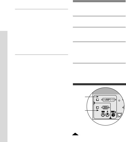
MODEL EL-100DT
(refer to fig. 3)
4You have the option of attaching a Sun console or a PC console. The PC console connects to the Alternate Connection jacks. Enabling one set of console jacks disables the other set. If you wish to connect a PC console then you must move its DIP switch. If you are tiering an EL-100DT switch from a primary switch that has a PC console attached, then you must move the switch to enable Alternate Connection. For the procedure see table
Enabling Alternate Connection on EL-100DT.
To attach a Sun console:
Connect the monitor and keyboard cables to its respective jacks in the “Sun Console Connection” on the back panel of the switch.
To attach a PC console:
Connect the mouse, monitor, and keyboard cables to their respective jacks in the Alternate Connection area on the back panel of the switch.
Enabling Alternate Connection on EL-100DT
FOR ATTACHING A PC CONSOLE
1Unplug the power cable, if it is connected, from the switch.
2Remove the two screws holding the access cover on the bottom of the unit.
3Inside the unit, set switch 1-1 to the On position to enable the Alternate Connection jacks, the Off position to enable the Sun Console Connection jacks.
4Replace the access cover.
Sun |
|
console |
Reset |
|
Sun Console Connection |
|
Alternate Connection |
PC |
|
console |
K |
|
Aux |
3 Console connection for EL-100DT
20
A P E X O U T L O O K S W I T C H E S
CONNECTING THE PRIMARY SWITCH TO A SECONDARY
SWITCH (TIERING)
Tiered configurations
Multi-switch systems or tiered configurations allow the greatest flexibility and capacity. In a tiered system, the OutLook switch connected to the console becomes the “primary” switch. Tiers consist of one or more “secondary” OutLook switches, which are connected to the computer ports on the primary switch. One 8-port primary unit can accommodate eight secondary switches and access up to 64 servers. One 10-port primary unit can accommodate ten secondary switches and access up to 100 servers.
Adding a secondary switch while the system is running
If you are installing a secondary switch to an existing OutLook switch system, you can attach the secondary switch while the system is running. To do this, you must first connect the mouse and video cables, then the keyboard cable. When you power on the secondary switch, the keyboard connection sends data to the primary switch allowing the secondary switch to boot up.
Whenever you add new devices to the system, you have to let the OutLook switch know you added an additional device. For procedure see Saving the Hardware Settings in Chapter 3.
Port numbering scheme
Secondary computer ports have a different numbering scheme from the primary computer ports. The port numbering scheme for the primary switch is Port 1, Port 2, Port 3, etc. The numbering scheme for the secondary switch is the number of the port on the primary switch followed by a dash, then the number of the port on the secondary switch. For example, a secondary switch connected to Port 2 on the primary switch has the number Port 2-1. Other ports on the secondary unit would be Port 2-2, Port 2-3, Port 2-4, etc. You can assign names to computers. For procedure see in Chapter 3 Assigning Unique Names to Computers.
Required Connectors for Switch
ALL MODELS EXCEPT EL-100DT
Mouse |
6-pin mini-DIN PS/2 style |
Keyboard |
6-pin mini-DIN PS/2 style |
Monitor |
HD15-pin VGA/SVGA style |
EL-100DT ONLY
Mouse/
Keyboard 8-pin mini-DIN
Monitor HD13W3
Switch Secondary a to Switch Primary the Connecting
21
Loading...