

Page 1
Magnum XS 450
-48 Vdc Power System
User’s Manual
Page 2

Table of Contents
1 SAFETY FIRST! ................................................................................................................. 1
1.1. W
1.2. G
ARNING SYMBOLS ..................................................................................................... 1
ENERAL PRECAUTIONS
:.............................................................................................. 1
2 INTRODUCTION ................................................................................................................ 2
2.1. G
H
OW TO USE THIS MANUAL
ENERAL INFORMATION
................................................................................................ 2
...................................................................................................... 4
3 INSTALLATION.................................................................................................................. 5
3.1. U
3.2. M
NPACKING EQUIPMENT
ECHANICAL INSTALLATION .......................................................................................... 5
............................................................................................... 5
Room / Location.................................................................................................................. 5
Mounting ............................................................................................................................. 7
Ventilation ........................................................................................................................... 7
3.3. AC P
OWER CONNECTIONS
........................................................................................... 8
AC Kit with Three Phase Spreader..................................................................................... 8
AC Kit with Phoenix Terminals Only................................................................................. 10
3.4. R
ECTIFIER SHELF AND MODULE INSTALLATION
............................................................. 11
Rectifier Shelf Serial Communications ............................................................................. 12
Rectifier Shelf Mechanical ................................................................................................ 12
Rectifier AC Input Connections ........................................................................................ 12
Rectifier Module Installation.............................................................................................. 13
3.5. DC D
ISTRIBUTION MODULE INSTALLATION
................................................................... 13
Module Selection .............................................................................................................. 13
Merlin Gerin 28 Circuit Breaker Module Installation ......................................................... 14
Merlin Gerin 12 Circuit Breaker Module Installation ......................................................... 15
NH2 Fuse Module Installation .......................................................................................... 16
3.6 DC C
ABLING GENERAL INSTRUCTIONS
3.7 DC D
ISTRIBUTION INSTALLATION.................................................................................... 18
.............................................................................. 17
Circuit Breaker Installation................................................................................................ 18
Installing circuit breakers in a 28 Circuit Breaker Module on the DIN rail ........................ 19
Installing circuit breakers in a 12 CB Module on the DIN rail ........................................... 20
Installing circuit breaker wiring (both types of circuit breaker modules)........................... 20
Installing a fuse in the NH2 Fuse Module......................................................................... 22
DC Load Return Module Installation................................................................................. 22
DC Load Return cable connections.................................................................................. 23
3.8 B
ATTERY INSTALLATION
................................................................................................. 23
Battery Tray Installation .................................................................................................... 23
Battery Installation ............................................................................................................23
Battery Disconnect Module Installation ............................................................................ 23
Negative Battery Cable Connections................................................................................ 24
Battery Return Module Installation ................................................................................... 25
Positive Battery Cable Connections ................................................................................. 25
Battery Temperature Probe Installation............................................................................ 25
3.9 DC S
3.10 M
ONITORING AND RELAY OUTPUT CONNECTIONS
YSTEM GROUNDING
.............................................................................................. 26
........................................................ 26
Network Management Card.............................................................................................. 26
“Smart” Cable DB9 Connection ........................................................................................ 27
RJ45 Ethernet Connector ................................................................................................. 27
Magnum XS 450 Power System –48 VDC User’s Manual Page ii
Page 3

Relay Output Connections................................................................................................ 27
External Alarm Input Connections .................................................................................... 28
4 COMMISSIONING............................................................................................................ 29
4.1 P
RE-COMMISSIONING INSPECTION
.................................................................................... 29
Environment...................................................................................................................... 29
Electrical Installation .........................................................................................................29
Battery Visual and Safety Inspection................................................................................ 29
4.2 C
OMMISSIONING
............................................................................................................ 30
Initial Set-up ...................................................................................................................... 30
AC Power Up .................................................................................................................... 30
DC Power Up: ................................................................................................................... 30
Rectifier Test:.................................................................................................................... 30
Battery Power Up.............................................................................................................. 30
LVD Test ........................................................................................................................... 31
Circuit Breaker/ Fuse Test: ............................................................................................... 31
User Inputs........................................................................................................................ 31
Output Relay 1: .................................................................................................................31
Battery Temperature Compensation ................................................................................ 31
4.3 F
INAL INSPECTION
:........................................................................................................ 32
5 OPERATION..................................................................................................................... 33
5.1 T
5.2 R
ECHNICAL DESCRIPTION
ECTIFIER MANAGEMENT .............................................................................................. 33
.............................................................................................. 33
AC Input Power................................................................................................................. 33
DC Output Power.............................................................................................................. 33
Rectifier alarms reporting.................................................................................................. 33
System Voltage Control .................................................................................................... 33
Rectifier Current................................................................................................................ 33
5.3 DC D
ISTRIBUTION
......................................................................................................... 34
DC Distribution Module..................................................................................................... 34
DC Return Module ............................................................................................................ 34
5.4 B
ATTERY MANAGEMENT
................................................................................................ 34
Battery Disconnect Module............................................................................................... 34
Battery Return Module...................................................................................................... 34
Battery Shelves.................................................................................................................34
Battery Cabinet .................................................................................................................34
5.5 C
USTOMER INTERFACE BOARD
...................................................................................... 35
Alarm Outputs (Output Relays) ........................................................................................ 35
External Alarm Inputs (Input Relays)................................................................................ 35
6 PREVENTIVE MAINTENANCE ....................................................................................... 36
6.1 E
6.2 I
QUIPMENT
NSPECTION
.................................................................................................................. 36
.................................................................................................................. 36
Environmental Inspection ................................................................................................. 36
System Visual and Safety Inspection ............................................................................... 36
Battery Visual and Safety Inspection................................................................................ 36
6.3 T
EST ............................................................................................................................ 37
System Voltage Test......................................................................................................... 37
Rectifier Current Test........................................................................................................ 37
Rectifier Current Share Test ............................................................................................. 37
System Current Test......................................................................................................... 37
Rectifier Alarm Test .......................................................................................................... 37
Magnum XS 450 Power System –48 VDC User’s Manual Page iii
Page 4

System Temperature Test ................................................................................................ 38
Battery Current Test ......................................................................................................... 38
Battery Temperature Test................................................................................................. 38
LVD Test ........................................................................................................................... 38
Battery Preventive Maintenance Procedure..................................................................... 39
6.4 F
INAL INSPECTION
:........................................................................................................ 39
7 SPECIFICATIONS............................................................................................................ 40
7.1 AC I
7.2 M
7.3 E
7.4 C
ECHANICAL
NVIRONMENTAL........................................................................................................... 40
OMPLIANCE
DCPM28HN54SH0 R
NPUT
................................................................................................................. 40
................................................................................................................. 41
ECTIFIER
..................................................................... 40
8 APC WORLDWIDE CUSTOMER SUPPORT .................................................................. 42
9 LIMITED PRODUCT WARRANTY .................................................................................. 43
Entire contents copyright © 2003 American Power Conversion. All rights reserved.
Reproduction in whole or in part without permission is prohibited. APC and the APC
logo are trademarks or registered trademarks of American Power Conversion
Corporation. All other trademarks, product names, and corporate names are the
property of their respective owners and are used for informational purposes only
Magnum XS 450 Power System –48 VDC User’s Manual Page iv
Page 5

Revision History
Revision Date By Description
990-1557 Revision 1 20 Oct, 2003 JPF Initial Release
990-1557A Revision 2 30 MAR 2004 BET Update to include Battery Cabinet
Table of Figures
FIGURE 2.1-1 MAGNUM XS 450 POWER PLANT ............................................................................2
FIGURE 2.1-2 POWER SYSTEM BLOCK DIAGRAM ....................................................................... 3
FIGURE 3.2-1 DOOR CLEARANCE DIMENSIONS ........................................................................... 6
FIGURE 3.2-2 FLOOR MOUNTING DIMENSIONS ...........................................................................7
FIGURE 3.3-1 AC KIT WITH THREE PHASE SPREADER (SHOWN WITH SINGLE POLE
BREAKERS) ................................................................................................................................... 9
FIGURE 3.3-2
FIGURE 3.3-3 RECOMMENDED TORQUES FOR TERMINAL BLOCK CONNECTIONS .......... 10
FIGURE 3.3-4 AC INPUT ENTRY WITH INDIVIDUAL RECTIFIER ENTRY (SHOWN WITH
SINGLE POLE CIRCUIT BREAKER OPTION)......................................................................... 11
FIGURE 3.4-1 RECTIFIER SWITCH SETTINGS .............................................................................. 12
FIGURE 3.4-2
FIGURE 3.5-1 28 CIRCUIT BREAKER MODULE ........................................................................... 14
FIGURE 3.5-2 12 CIRCUIT BREAKERS MODULE ......................................................................... 16
FIGURE 3.5-3 NH2 FUSE MODULE ..................................................................................................17
FIGURE 3.7-1 MERLIN GERIN CIRCUIT BREAKER...................................................................... 18
FIGURE 3.7-2 MERLIN GERIN 28 CB MODULE INSTALLATION DETAIL ...............................19
FIGURE 3.7-3 MERLIN GERIN 12 CB MODULE INSTALLATION DETAIL ...............................20
FIGURE 3.7-4 CB ALARM INTERFACE BOARD (28 CIRCUIT BREAKER MODULE).............. 21
FIGURE 3.7-5 CB ALARM EXPANSION BOARD (12 CIRCUIT BREAKER MODULE) ............. 21
FIGURE 3.7-6 NH2 FUSE CONNECTIONS ....................................................................................... 22
FIGURE 3.7-7 LARGE LOAD AND SMALL LOAD RETURN MODULE ...................................... 23
FIGURE 3.8-1 BATTERY CABLE CONNECTIONS ......................................................................... 24
FIGURE 3.8-2 BATTERY RETURN MODULE ................................................................................. 25
FIGURE 3.8-3 TYPICAL LOCATION OF BATTERY TEMPERATURE PROBE ........................... 26
FIGURE 3.10-1 NETWORK MANAGEMENT CARD ....................................................................... 26
RECOMMENDED TORQUES ON INPUT CONNECTORS..................................... 10
RECOMMENDED TORQUES ON RECTIFIER CONNECTORS ............................ 12
Magnum XS 450 Power System –48 VDC User’s Manual Page v
Page 6
1 Safety First!
It is very important to follow all safety procedures when unpacking, installing and operating
any sort of power equipment.
1.1. Warning Symbols
CAUTION: An indication that special care is required to prevent injury,
1.2. General Precautions:
equipment damage or misuse
WARNING: An indication of an electrical hazard that may cause serious
personal injury or death, catastrophic equipment damage or site
destruction.
WARNING: Hazardous ac voltage levels are present inside the power
system. Keep the ac input cover in place when the system is operational
or energized.
WARNING
the -48Vdc distribution connection area of the plant. Accidental shorting
of distribution conductors can cause arcing and high currents that can
cause serious burns or other physical harm. It is recommended that:
Specific CAUTION and WARNING will be placed in manual where appropriate.
• Remove any jewelry, rings or watches while working on this
• Use insulated wrenches, screwdrivers, cutters, pliers and other
WARNING: Ensure that all of the dc and external ac circuit breakers are
in the OFF position prior to connecting service to the power plant.
Confirm that all voltages have been removed including any battery
sources before proceeding
: Hazardous energy levels are present on bare conductors in
equipment.
tools.
.
Magnum XS 450 Power System –48 VDC User’s Manual Page 1
Page 7
2 Introduction
2.1. General Information
DC Power Plants from APC have unique features that make them easy to install, maintain,
and upgrade. The rectifier units are modular and truly “hot-pluggable” into the shelf
assembly without any separate ac wiring. The shelf assemblies are also modular and can be
added when system capacity needs to be expanded. All system settings are made from the
system controller that provides monitoring and control functions for each component of the
system as well as alarm listings for system diagnosis and maintenance.
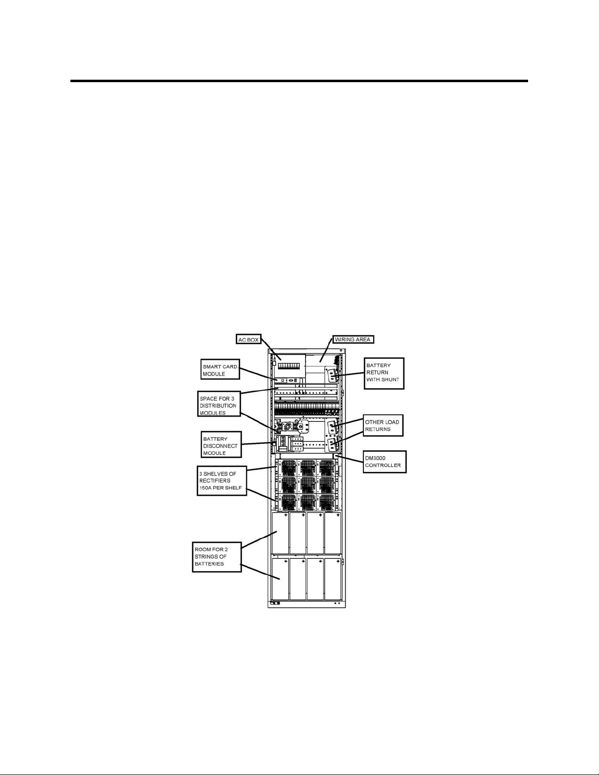
The APC Magnum XS 450 Power System is a modular stand-alone -48V dc power plant. It
is configurable in such a manner that it will support most typical applications within the
specified current range without special application engineering or assistance. A wide variety
of dc output distribution and battery disconnect modules are supported. An optional low
voltage disconnect (LVD) can be provided on either the battery or the load side. A 450ampere system is shown in Figure 2.1-1. A block diagram of a typical configuration of the
power system is shown in Figure 2.1-2
.
Figure 2.1-1 Magnum XS 450 Power Plant
Magnum XS 450 Power System –48 VDC User’s Manual Page 2
Page 8
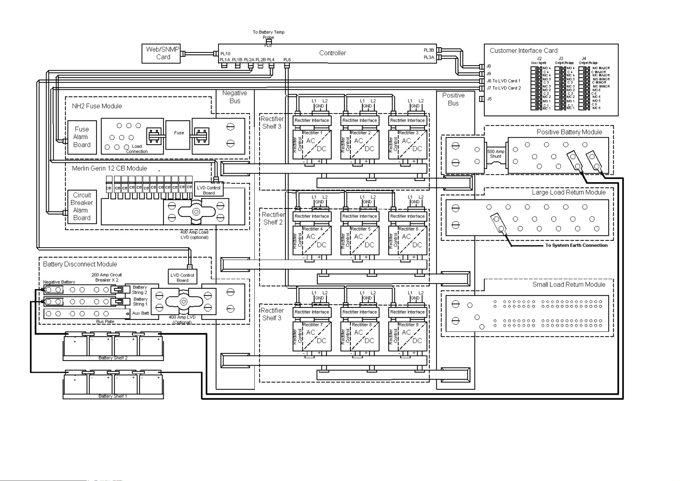
Magnum XS 450 Power System –48 VDC User’s Manual Page 3
Figure 2.1-2 Power System Block Diagram
Page 9

How to Use This Manual
Each section of this manual can be read in any order and should provide a complete
explanation of the subject described by the title. However, the sequence of the sections is
designed to provide a typical step-by-step process for successful use of the equipment.
Safety First!
Introduction
Installation
Commissioning
Operation
Preventative
Maintenance
Specifications
APC Worldwide
Customer Support
Safety symbol description and general precautions.
Brief system preview and explanation of manual usage.
How to unpack and install the equipment.
The procedure for commissioning the equipment for initial use
Specifics of controls settings and indicators used to operate the
unit.
Procedures for performing preventative maintenance on the
equipment.
Power plant and rectifier specifications.
How to contact APC for customer support.
Warranty
Equipment warranty terms and conditions.
Magnum XS 450 Power System –48 VDC User’s Manual Page 4
Page 10
3 Installation
3.1. Unpacking Equipment
Remove equipment from packing material and inspect for shipping damage or missing items.
It is important to report damage or material shortages to the shipping carrier while a
representative is on site.
If concealed damage or material shortages are found at a later time, contact the shipper to
make arrangements for inspection and claim filing. Refer to
necessary to return equipment to APC.
Section 7
in the event it is
CAUTION
used to remove equipment from packing.
PLEASE RECYCLE: The shipping materials can be recycled. Please
save them for later use or dispose accordingly.
: Appropriate lifting techniques and safety equipment should be
3.2. Mechanical Installation
Room / Location
NOTE:
enclosure that is accessible only to qualified persons in accordance with the local regulatory
authority.
Prior to installation, drawings, floor loading requirements, external alarm points, ac service
entrance, and grounding schemes should all be checked and confirmed. If batteries are to
be mounted in a room separate from the power plant, careful attention should be paid to
battery cable voltage drop effects. Environmental operating temperatures and
ventilation/cooling considerations should also be noted, not just for the power system but
also for all other equipment that may reside in the power room area.
The power system has a door on the front that can be hinged to swing either way. The
power system has two doors on the rear that swing out. The doors have spring loaded hinge
pins so that they can be removed for servicing. Dimensions are shown in Figure 3.2-1. The
sides have panels that are mounted flush with the frame. A key-lock on the top of the panels
holds the panels in place.
The APC Magnum XS 450 Power System is to be installed in a room, vault, or similar
Magnum XS 450 Power System –48 VDC User’s Manual Page 5
Page 11
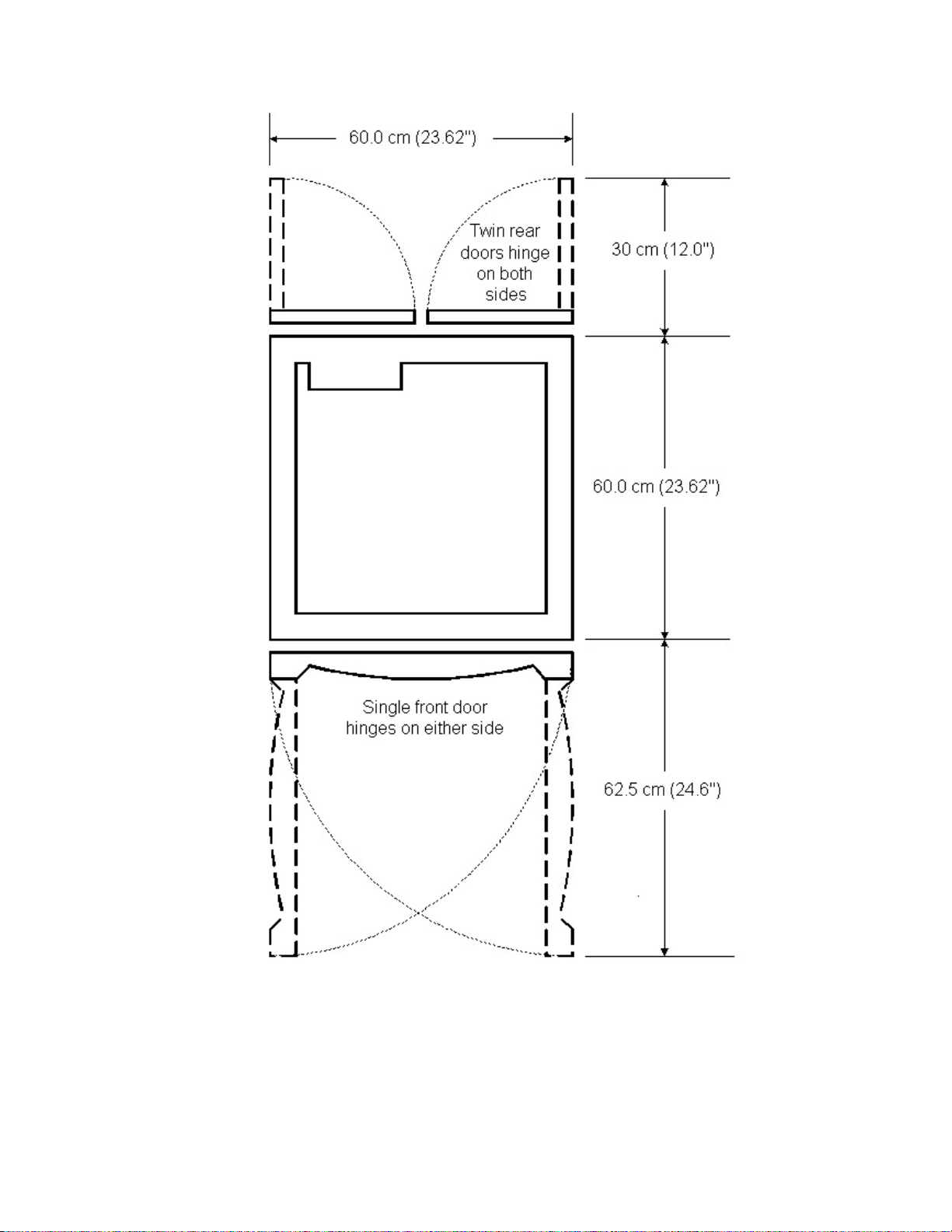
Figure 3.2-1 Door Clearance Dimensions
Magnum XS 450 Power System –48 VDC User’s Manual Page 6
Page 12
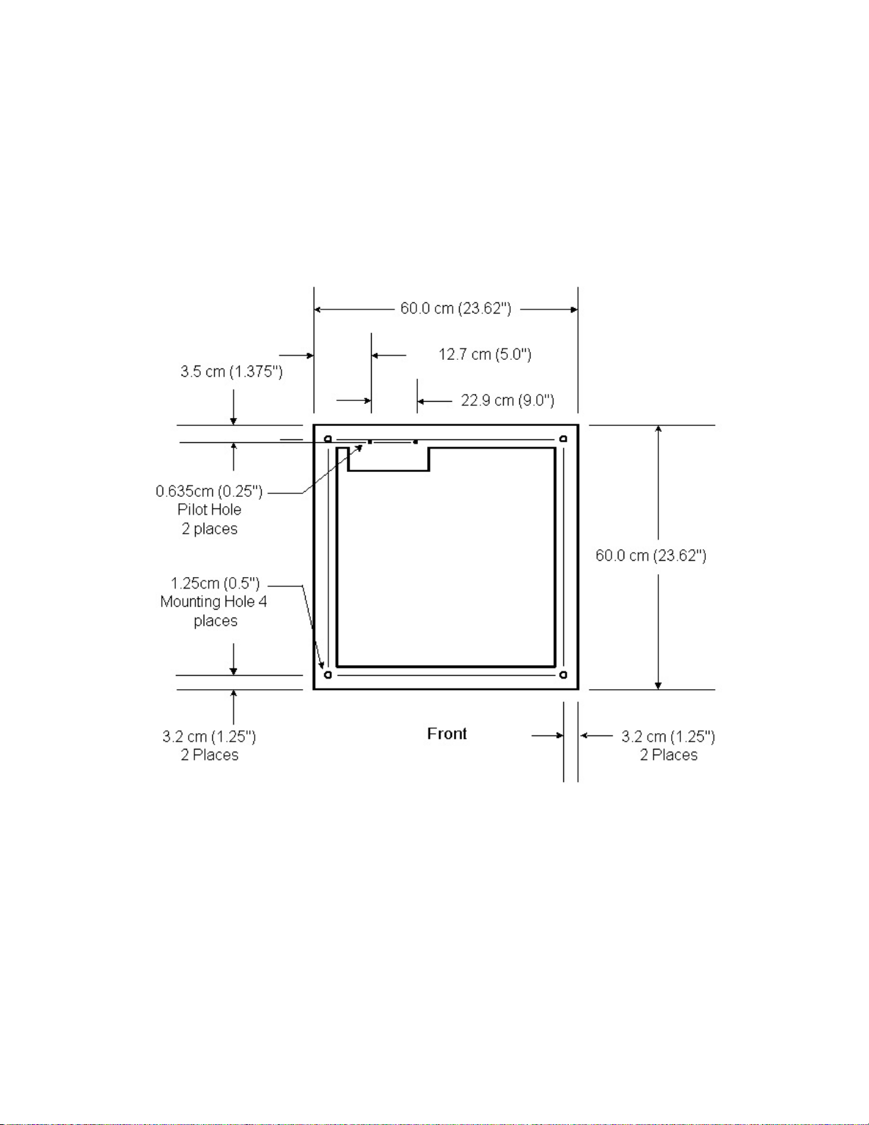
Mounting
The unit is self-supporting, but designed to be bolted to the floor of the housing structure.
Figure 3.2-2 shows the footprint of the box frame and the mounting points with dimensions.
Systems with multiple box frames are bolted together with each frame touching, side by side.
The side panels where two frames touch are removed so that cables can pass between the
frames. A kit with the necessary hardware to bolt two cabinets together (0M-3441) is
available from APC.
Figure 3.2-2 Floor Mounting Dimensions
Ventilation
The rectifier modules for this system have fans that provide front-to-rear airflow for internal
cooling. The Magnum XS 450 Power System frame should be mounted such that there is
free airflow to the front and rear of the unit. [Refer to
Section 7.3
for environmental
characteristics.] Free airflow should be ensured so that the power system can provide full
power at ambient temperature without de-rating.
Magnum XS 450 Power System –48 VDC User’s Manual Page 7
Page 13
3.3. AC Power Connections
WARNING
: Ensure that all of the external dc and ac circuit breakers are in
the OFF position prior to connecting service to the power plant. Confirm
that all voltages have been removed including any battery sources before
proceeding
.
The Magnum XS 450 Power System requires the supply of a nominal 230 Vac single-phase,
or three-phase 415/230 V, 50/60 Hz power to the ac input terminal block connections.
However, it will operate off of voltages in the range of 176 – 293 V. The maximum possible
dc Current Output of the rectifiers is less than the typical value of 50A per rectifier at ac input
voltages in the range of 176 to 195 Vac. As the ac input voltage decreases, the maximum dc
Output current follows a de-rating curve. For further details on the de-rating curve, please
refer to the specification sheet for the DCPM28HN54SH0 Rectifier available from APC
Customer service in your area or your local APC distributor.
The ac input enclosure is located at the top of the Magnum XS 450 Power System housing.
AC wiring, from the ac input terminal block connections to the hot-pluggable ac input
connector for each rectifier, is factory installed. An ac branch circuit breaker of 50 A is
recommended for each phase if using the three phase set-up. An ac branch circuit breaker
of 20A is recommended for each single-phase connection.
WARNING: Hazardous ac voltage levels are present inside the power
system. Keep the ac input cover in place when the system is operational
or energized.
AC Kit with Three Phase Spreader
A terminal block for connection of ac input power and “Earth Ground” is provided. The
terminal block is labeled as E, NEUT, L1, L2 and L3. At the front of the ac input enclosure,
either single pole or two pole circuit breakers are provided for each rectifier. The single pole
option breaks the “hot” wire going to each individual circuit breaker. The two-pole breaker
option simultaneously breaks both the “hot” wire and the Neutral wire.
The top of the ac input enclosure is provided with four pilot holes for easy alignment of the
desired conduit entry holes. A duct is provided so that the ac input connections can be
routed up through the unit from the bottom. Two 31.75 mm (1-1/4 inch) conduit entry holes
are provided in the bottom of the cabinet.
When a single three phase ac input line is run to each system, a large line spreader strip is
provided for connection of the ac Input. The suggested wire size for the Neutral and Ground
lines are 35 mm
16 mm
2
(#6 AWG) rated at 90°C or higher; however, the ambient temperature and number of
2
(#2 AWG) rated at 90°C or higher The suggested wire size for the lines is
wires in a conduit must also be considered in accordance with all applicable code
requirements.
If the ac input power is provided from a three-phase distribution panel. The left rectifier in
each shelf is powered from the terminal block labeled L1. The middle rectifier in each shelf is
Magnum XS 450 Power System –48 VDC User’s Manual Page 8
Page 14

powered from the terminal block labeled L2. The right rectifier in each shelf is powered from
the terminal block labeled L3.
AC Line 1
L1
AC
DC
AC Line 2
AC Line 3
AC Neutral
Earth
Ground
L2
L3
Neut.
E
AC
AC
AC
AC
AC
AC
AC
AC
DC
DC
DC
DC
DC
DC
DC
DC
Figure 3.3-1 AC Kit with Three Phase Spreader (shown with single pole breakers)
Magnum XS 450 Power System –48 VDC User’s Manual Page 9
Page 15

Neutral Input
Wire Size (AWG) Wire Size (mm2) Max Torque (in-lb) Max Torque (N-m)
350 kcmil – 2 Cu 185 – 35 Cu 275 31.75
L1, L2, and L3 Input
Wire Size (AWG) Wire Size (mm2) Max Torque (in-lb) Max Torque (N-m)
2/0 – 6 Cu 70-16 Cu 125 13.5
Earth Ground Input
Wire Size (AWG) Wire Size (mm2) Max Torque (in-lb Max Torque (N-m)
4/0 – 6 Cu 95 – 16 Cu 275 31
Figure 3.3-2 Recommended Torques on Input Connectors
AC Kit with Phoenix Terminals Only
A terminal strip for ac input power connection and a separate “Earth Ground” bar for
connection of the safety ground wire(s) is provided. The terminal block is labeled as L and N
for each rectifier with the terminal block for rectifier one being the leftmost. At the front of the
ac input enclosure, optional single pole or two pole circuit breakers may be provided for each
rectifier. The single pole option breaks the “hot” wire going to each individual circuit breaker.
The two-pole breaker option simultaneously breaks both the “hot” wire and the Neutral wire.
The system may also have no circuit breakers.
The top of the ac input enclosure is provided with four pilot holes for easy alignment of the
desired conduit entry holes. A duct is provided so that the ac input connections can be
routed up through the unit from the bottom. Two 31.75 mm (1-1/4 inch) conduit entry holes
are provided in the bottom of the cabinet.
Individual ac input lines are run for each rectifier. The suggested wire size is 6 mm
2
(#10
AWG) rated at 90°C or higher, however, the ambient temperature and number of wires in a
conduit must also be considered in accordance with all applicable code requirements.
Wire Size (AWG) Wire Size (mm
2
) Max Torque (in-lb) Max Torque (N-m)
6 - 10 Cu 16 –6 16 1.8
Figure 3.3-3 Recommended Torques for Terminal Block Connections
Magnum XS 450 Power System –48 VDC User’s Manual Page 10
Page 16

AC Line 1
AC Neutral 1
AC Line 2
AC Neutral 2
AC Line 3
AC Neutral 3
AC Line 4
AC Neutral 4
AC Line 5
AC Neutral 5
AC Line 6
AC Neutral 6
AC Line 7
AC Neutral 7
AC Line 8
AC Neutral 8
AC Line 9
AC Neutral 9
L
N
L
N
L
N
L
N
L
N
L
N
L
N
L
N
L
N
AC
AC
AC
AC
AC
AC
AC
AC
AC
DC
DC
DC
DC
DC
DC
DC
DC
DC
Earth Ground
GND G1
Figure 3.3-4 AC Input Entry with Individual Rectifier Entry (shown with single pole circuit breaker
option)
3.4. Rectifier Shelf and Module Installation
Since expandability is so important, rectifiers and rectifier shelves are very easy to install. A
rectifier shelf will hold up to 3 rectifiers. There is individual ac input wiring for each rectifier.
Each rectifier will communicate to the controller through a ten-pin ribbon cable.
WARNING: Ensure that all of the ac circuit breakers for any rectifier shelf
to be added are in the OFF position prior to installing the additional shelf/
shelves.
Magnum XS 450 Power System –48 VDC User’s Manual Page 11
Page 17

Rectifier Shelf Serial Communications
Program the binary address of each rectifier in the shelf using S1 on the rectifier interface
card. These are located at the back of each rectifier slot. All switches ON will give an
address of zero (rectifier 1). Set switches per the following table:
S1 Switch Position
Address 1 Address 2 Address 3 Address 4 Address 5 Address 6 Address 7 Address 8
Rectifier 1 ON ON ON ON ON ON ON ON
Rectifier 2 OFF ON ON ON ON ON ON ON
Rectifier 3 ON OFF ON ON ON ON ON ON
Rectifier 4 OFF OFF ON ON ON ON ON ON
Rectifier 5 ON ON OFF ON ON ON ON ON
Rectifier 6 OFF ON OFF ON ON ON ON ON
Rectifier 7 ON OFF OFF ON ON ON ON ON
Rectifier 8 OFF OFF OFF ON ON ON ON ON
Rectifier 9 ON ON ON OFF ON ON ON ON
Figure 3.4-1 Rectifier Switch Settings
Plug the 10-pin ribbon cable supplied with the rectifier shelf into J2 of each rectifier interface
card in the shelf. Plug the 10-pin ribbon cable into the 10-pin ribbon cable that goes down
the back of the power system.
Rectifier Shelf Mechanical
Install the rectifier shelf from the front, holding the shelf horizontal. Align the rear shelf
alignment slot with the alignment stud on the side box supports on both sides of the shelf.
Hold the shelf horizontally to ensure the proper mating of the shelf bus with the rear bus
clips. The shelf may now be pushed to the rear until the shelf flanges are flat against the
front box support. Ensure that the shelf rear bus and the rear bus clips are properly mated.
Install 4 M5 machine screws to secure the front of the shelf to the power bay
Rectifier AC Input Connections
Each rectifier interface card on the shelf has a 3-pin connector J1 for the ac input to that
rectifier. Insert the mating connector from the ac cable assembly into J1. Route the wires up
to the ac input assembly. Connect the green/yellow wire from the ac cable assembly to the
Ground connection in the ac input assembly. If two pole rectifier circuit breakers are
installed, connect the red and the black wire from the ac cable assembly to the circuit
breaker. If single pole rectifier circuit breakers are installed, connect the red wire from the ac
cable assembly to the circuit breaker. Connect the black wire to the ac input terminal strip. If
no rectifier circuit breakers are installed, connect the red and the black wire to the ac input
terminal strip.
Wire Size (AWG) Wire Size (mm2) Max Torque (in-lb) Max Torque (N-m)
10 - 14 Cu 6 – 2.5 Cu 20 2.25
Figure 3.4-2 Recommended Torques on Rectifier Connectors
Magnum XS 450 Power System –48 VDC User’s Manual Page 12
Page 18

Rectifier Module Installation
WARNING
installed incorrectly. Before rectifier installation, ensure proper battery
Rectifier modules are hot-swappable. The rectifier modules are generally shipped in
separate containers. Remove the rectifier from its shipping container. Using a flat blade
screwdriver, loosen the pawl latch (counter-clockwise) on the rectifier, until the latch is
recessed inside the rectifier. Slide the rectifier module into the shelf between the guides until
it is fully seated. Tighten the rectifier pawl latch (clockwise). The pawl latch is a multi-turn
device and should be turned until the latch holds the rectifier snugly. Since all adjustments
are made from the system control unit, no rectifier adjustments are necessary.
CAUTION: Rectifier fan inlet filters are available for dusty or hostile
Fan inlet filters are available for order from APC (Part Number 1MAF28).
polarity.
environments. Failure to periodically check and clean filters can lead to
rectifier shutdown due to over temperature and produce power plant failure.
: Rectifier dc output circuits would be damaged if battery were
3.5. DC Distribution Module Installation
Module Selection
A variety of dc distribution modules are available. These modules are designed to provide a
convenient means of attaching the dc load cables. These modules also provide over-current
protection, low voltage disconnect and/or load shed capability. The modules that are
attached to the 54-volt return bus bars are designed to provide a convenient means of
attaching the dc return cables.
SKU Number Description LVD Option Qty Allowed in System
0M-2189 Merlin Gerin 12 Circuit Breaker No LVD 3
0M-2188 Merlin Gerin 12 Circuit Breaker 400 A LVD 3
0M-2185 NH2 Fuse No LVD 3
0M-2187 NH2 Fuse 400 A LVD 3
0M-2186 Merlin Gerin 28 Circuit Breaker No LVD 1
0M-2579 Merlin Gerin 28 Circuit Breaker 400 A LVD 1
Table 3.5-1 DC Distribution Module Selector Table
Magnum XS 450 Power System –48 VDC User’s Manual Page 13
Page 19

Merlin Gerin 28 Circuit Breaker Module Installation
WARNING: Hazardous energy levels are present on bare conductors in
the -48Vdc distribution connection area of the plant. Accidental shorting of
distribution conductors can cause arcing and high currents that can cause
serious burns or other physical harm. It is recommended that:
• Remove any jewelry, rings or watches while working on this
equipment.
• Use insulated wrenches, screwdrivers, cutters, pliers and other
tools.
The Merlin Gerin 28 Circuit Breaker Module requires two adjacent open module positions.
The wiring support bracket is mounted directly above the Merlin Gerin 28 Circuit Breaker
module. Position the wiring support bracket in the top open position. Use M5 hardware to
secure the front lip of the wiring support bracket above the to the power system frame.
Connect the two alarm cables to the controller backplane.
Figure 3.5-1 28 Circuit Breaker Module
Position the circuit breaker module below the wiring support bracket. Insert the module in
the power system such that the holes in the module dc bus line up with the holes in the
power system dc bus. Use M8 hardware to secure the buses together. Use M5 hardware to
secure the front lip to the power system frame. Use M6 hardware to secure the rear of the
module to the power system frame.
Connect the LVD power wiring to the power bus observing proper polarity. Connect the LVD
control cable to the customer interface card.
The alarm signal of each individual circuit breaker [see Installing circuit breaker wiring
(both types of circuit breaker modules)
for specific alarm cable wiring instructions] is
connected to a terminal block on the CB Interface Board (mounted directly above the circuit
breaker module). Each alarm wire is placed in the terminal block position with the number
corresponding to the position of the circuit breaker in the system. The CB Interface Board is
connected to the controller via a 50-conductor cable that plugs into the J3 connector on the
CB Interface Board. The 50-conductor cable splits into (2) DB-25 connectors that plug into
connectors PL1A and PL1B on the controller backplane.
Magnum XS 450 Power System –48 VDC User’s Manual Page 14
Page 20

Merlin Gerin 12 Circuit Breaker Module Installation
WARNING: Hazardous energy levels are present on bare conductors in
the -48Vdc distribution connection area of the plant. Accidental shorting of
distribution conductors can cause arcing and high currents that can cause
serious burns or other physical harm. It is recommended that:
• Remove any jewelry, rings or watches while working on this
equipment.
• Use insulated wrenches, screwdrivers, cutters, pliers and other
tools.
The Merlin Gerin 12 Circuit Breaker Module requires one open module position. Insert the
module in the power system such that the holes in the module dc bus line up with the holes
in the power system dc bus. Use M8 hardware to secure the buses together. Use M5
hardware to secure the front lip to the power system frame. Use M6 hardware to secure the
rear of the module to the power system frame. Connect the alarm cable to the controller
backplane.
Connect the LVD power wiring to the power bus observing proper polarity. Connect the LVD
control cable to the customer interface card.
The alarm signal of each individual circuit breaker [see Installing circuit breaker wiring
(both types of circuit breaker modules) for specific alarm cable wiring instructions] is
connected to a terminal block on the CB Extender Board (mounted directly above the circuit
breaker module). Each alarm wire is placed in the terminal block position with the number
corresponding to the position of the circuit breaker in the system. The CB Extender Board
(mounted directly above the circuit breaker module) is connected to the controller via a 26conductor cable that plugs into the J2 connector on the CB Extender Board. The 26conductor cable has a DB-25 connector on the other end that plugs into connector PL2A on
the controller backplane. The DB-25 end of the cable is only 25 pins, so the 26
th
conductor is
not connected to this connector.
If a second 12 Circuit Breaker module is installed in a system, then the CB Extender Board
for that module is connected via a 26 pin connector from connector J2 to connector J3 of the
CB Extender Board of the first 12 Circuit Breaker module. If a third 12 Circuit Breaker
Module is installed in the system, it is connected to the controller via a 26-conductor cable
that plugs into the J2 connector on the CB Extender Board. The other end of the 26conductor cable has a DB-25 connector that plugs into connector PL2B on the controller
backplane board.
Magnum XS 450 Power System –48 VDC User’s Manual Page 15
Page 21

Figure 3.5-2 12 Circuit Breakers Module
CIRCUIT BREAKER RATING ORDERING NUMBER
Merlin Gerin C60HC 4 A 0M-3318
Merlin Gerin C60HC 10 A
Merlin Gerin C60HC 20 A
Merlin Gerin C60HC 32A
Merlin Gerin C60HC 40A
Merlin Gerin C60HC 50A
Merlin Gerin C60HC 63A
Merlin Gerin C120HC 80A
Merlin Gerin C120HC 100A
Merlin Gerin C120HC 125A
0M-3314
0M-3315
0M-3316
0M-3317
0M-3319
0M-3311
0M-3313
0M-3312
0M-3310
Table 3.5-2 Circuit Breakers Available from APC
NH2 Fuse Module Installation
WARNING: Hazardous energy levels are present on bare conductors in
the -48Vdc distribution connection area of the plant. Accidental shorting
of distribution conductors can cause arcing and high currents that can
cause serious burns or other physical harm. It is recommended that:
Remove any jewelry, rings or watches while working on this
•
equipment.
Use insulated wrenches, screwdrivers, cutters, pliers and other
•
tools.
The NH2 Fuse Module requires one open module position. Insert the module in the power
system such that the holes in the module dc bus line up with the holes in the power system
Magnum XS 450 Power System –48 VDC User’s Manual Page 16
Page 22

dc bus. Use M8 hardware to secure the buses together. Use M5 hardware to secure the
front lip to the power system frame. Use M6 hardware to secure the rear of the module to
the power system frame.
Figure 3.5-3 NH2 Fuse Module
Connect the LVD power wiring to the power bus observing proper polarity. Connect the LVD
control cable to the customer interface card.
The alarm signal of each individual fuse is connected from a ring terminal secured to the fuse
module with a 5mm screw placed in one of the threaded holes provided on the load side of
the fuse module. The other end of each alarm wire is connected to the terminal block
position on the Fuse Interface Board with a number corresponding to the position of the fuse
in the system. The Fuse Interface Board connects to the controller via a 16 conductor to DB25 cable that connects to connector PL4 on the controller backplane board.
FUSE RATING ORDERING NUMBER
100 A fuse 0M-3390
200 A fuse 0M-3393
300 A fuse 0M-3392
400 A fuse 0M-3391
Table 3.5-3 NH2 Style Fuses Available from APC
3.6 DC Cabling General Instructions
It is very important to keep load cabling separate from battery cabling. For example, hooking
load cables to a module used as battery disconnect will tie the battery directly to the load.
Magnum XS 450 Power System –48 VDC User’s Manual Page 17
Page 23

Hooking the load cables to a module used as a battery return will cause erroneous battery
current readings.
The dc load cable(s) should be sized to limit the voltage drop from the Magnum XS 450
Power System to the loads per system design requirements. The cable(s) must also carry
the full load current during battery operation. During battery operation the voltage will be
lower and for constant power loads the current will typically be higher. If assistance is
required to determine the necessary cables for the application, contact your sales
representative or APC.
3.7 DC Distribution Installation
WARNING
Vdc distribution connection area of the plant. Accidental shorting of distribution
Circuit Breaker Installation
conductors can cause arcing and high currents that can cause serious burns or
other physical harm. It is recommended that:
• Remove any jewelry, rings or watches while working on this equipment.
• Use insulated wrenches, screwdrivers, cutters, pliers and other tools.
: Hazardous energy levels are present on bare conductors in the -48
Figure 3.7-1 Merlin Gerin Circuit Breaker
Magnum XS 450 Power System –48 VDC User’s Manual Page 18
WARNING: The circuit breakers (CBs) should be in the OFF position
prior to installation in the system.
Page 24

Installing circuit breakers in a 28 Circuit Breaker Module on the DIN rail
Figure 3.7-2 Merlin Gerin 28 CB Module Installation Detail
Install the Merlin Gerin Circuit Breaker (CB) to the mounting DIN Rail on the 0M-2186 or 0M2579 circuit breaker module with the DIN rail lock positioned toward the main bus. The C60
style CBs should be installed from left to right on the main bus and the C120 style CBs
should be installed from right to left on the main bus for the best use of the main bus
positions.
Enable the CB’s DIN rail lock (the CB may still be moved laterally on the DIN rail for final
positioning. Position the appropriate transition bus on the main bus and inserted in the
opened CB connection area. Secure the transition bus to the main bus with the two M4x16
machine screws (SEMs) provided. Tighten the CB connection tightening screw on the
transition bus.
Any combination of up to 28 Merlin Gerin circuit breakers may be installed on the 28 circuit
breaker module. There are two different types of circuit breaker available: the C60 series
circuit breaker and the C120 series circuit breakers. The two basic types of Merlin Gerin
circuit breakers may be installed in combination as shown in the table below.
Magnum XS 450 Power System –48 VDC User’s Manual Page 19
Page 25

C60 28 26 25 23 22 20 19 17 16 14
C120 0 1 2 3 4 5 6 7 8 9
Total 28 27 27 26 26 25 25 24 24 23
C60 13 11 10 8 7 5 4 2 1 0
C120 10 11 12 13 14 15 16 17 18 19
Total 23 22 22 21 21 20 20 19 19 19
Table 3.7-1 Circuit Breaker Mix Table
Installing circuit breakers in a 12 CB Module on the DIN rail
Install the C60 style Merlin Gerin Circuit Breaker to the mounting DIN Rail on the
0M-2188 or 0M-2189 module with the DIN rail lock positioned toward the bus
finger. Open the bus connection by loosening the bus side tightening screw.
Open the DIN rail lock. Slide the CB unto the bus finger until the front edge of the
CB clears the edge of the DIN rail. Lower the front edge of the CB onto the DIN rail
and slide the CB back until the edge of the DIN rail fully enters the CB rail slot #1.
Lower the rear of the CB onto the DIN rail. Slide the CB forward slightly to seat rail
slot #2. Engage the CB DIN rail lock. Tighten the CB connection screw on the bus
finger.
Figure 3.7-3 Merlin Gerin 12 CB Module Installation Detail
Installing circuit breaker wiring (both types of circuit breaker modules)
Insert the load wire and the flat spade of the alarm cable into the open load side of the CB.
Tighten the CB load side tightening screw. Route the alarm cable to the alarm PWB (trim the
wire length as required and strip the end of the wire approximately ¼ inch (6mm). Insert a
small bladed screwdriver into the small opening above the desired position and then insert
the stripped alarm that has been cut to length. Remove the screwdriver to capture the alarm
lead. Label the circuit breaker as desired using the label kit provided with the module. Dress
the load wire and the alarm cable as required to the lead support bracket.
Magnum XS 450 Power System –48 VDC User’s Manual Page 20
Page 26

Figure 3.7-4 CB Alarm Interface Board (28 circuit breaker module)
Figure 3.7-5 CB Alarm Expansion Board (12 circuit breaker module)
Magnum XS 450 Power System –48 VDC User’s Manual Page 21
Page 27

Installing a fuse in the NH2 Fuse Module
Insert the fuse into the fuse module until the tangs on each end of the fuse bottom out in the
socket.
Mounting
holes for
Fuse
Alarm
Cable
Figure 3.7-6 NH2 Fuse Connections
DC Load Return Module Installation
The modules that are attached to the Return bus are designed to provide a convenient
means of attaching the dc return cables. The battery return module has a shunt installed and
the load return modules do not. Table 3.7- will assist you in selecting the correct load return
module.
Part
Number
0M-2969 Small Load Return Bus M5 threaded holes on 1.59 mm (5/8 in.)
0M-2960 Large Load Return Bus M8 threaded holes on 2.54 mm (1 in.)
Description Lug Size Number of
Connections
40 M5; 1 set
centers.
of M8 holes
6
and 44.5 mm (1-3/4 in.) centers
Table 3.7-2 Load Return Selector Table
To install either return module, loosen the 4 M5 X 8 Phillips head screws on the back of the
module. The slotted screws will allow the module to be aligned precisely. Position the
module in an open return position in the unit. Align the holes in the return module with the
holes in the return bus and insert 2 M8 X 20 cap screws with lock washers and flat washers.
Align the holes in the return module with the holes in the front of the cabinet and insert 2 M5
Phillips screws. Tighten the M8 cap screws, then the M5 screws and finally the M4 screws in
the slots on the back of the module.
Magnum XS 450 Power System –48 VDC User’s Manual Page 22
Page 28

Figure 3.7-7 Large Load and Small Load Return Module
DC Load Return cable connections
The battery return module has a shunt installed and the load return modules do not. The
small return has 40 pairs of M5 threaded holes on 1.59 cm (5/8 in.) centers. One set of M8
threaded holes on 2.54 mm (1 in.) and 4.45 mm (1.75 in.) centers is also provided on the
small return module. The large return has 6 pairs of M8 threaded holes on 2.54 mm (1 in.)
and 4.45 mm (1.75 in.) centers
3.8 Battery Installation
WARNING
connections to the Magnum XS 450 Power System. Incorrect connection
Battery Tray Installation
Install Battery Shelf 1 in bottom of power system. Use M6 hardware in the lowest 2 holes on
each corner post to mount the battery shelf. Battery Shelf 2 is mounted 35.5 cm (14 in.)
above Battery Shelf 1.
Battery Installation
Each Battery tray is designed to hold four 12-Volt Valve Regulated Lead Acid (VRLA) type
Mono-block batteries. Always follow the battery vendor’s installation instructions for proper
set-up of batteries. Installation of batteries should also be done with due consideration to all
applicable local codes. The end user is responsible for meeting any and all local codes
issues, including, but not limited to, Battery Spill Containment Systems.
Battery Disconnect Module Installation
The Battery Disconnect Module requires one open module position and is typically installed
in the lowest position. Insert the module in the power system such that the holes in the
module dc bus line up with the holes in the power system dc bus. Use M8 hardware to
secure the buses together. Use M5 hardware to secure the front lip to the power system
frame. Use M6 hardware to secure the rear of the module to the power system frame.
Magnum XS 450 Power System –48 VDC User’s Manual Page 23
could cause severe equipment damage.
: Make certain that the battery polarity is correct when making
Page 29

Connect the LVD power wiring to the power bus observing proper polarity. Connect the LVD
control cable to the customer interface bus.
The alarm signal of each individual Battery Disconnect Switch is connected to the blade
terminals of the switch (C and N/C). The other end of the alarm cable is connected to the J2
terminal block (User Inputs) located on the Customer Interface Board. The alarm wires of
each individual Battery Disconnect Switch should be connected to the C and N/C terminals of
the User Input number corresponding to the position of the battery shelf in the system.
(Battery Shelf 1 Disconnect Switch Alarm to User Input 1, etc.) A 26-conductor cable to DB25 cable is used to connect the User Input signals from the Customer Interface Board to
connector PL3B on the connector backplane board.
Negative Battery Cable Connections
Connect the negative battery cables to the battery disconnect module. The battery
disconnect module is located near the middle of the power system on the left side as shown
in Figure 3-19 Battery Cable Connections. Each negative battery bus bar has three sets of
M6 threaded holes on 1 in. (25.5mm) centers.
The Battery Disconnect Module supports two internal battery strings and up to four external
battery strings in the battery cabinet. The two internal battery strings connect to the top two
battery buses and can be disconnected with the two circuit breakers. A battery disconnect
for each remote battery string is mounted in the top of the battery cabinet. The cable from
the battery disconnect in the battery cabinet is connected to the bottom battery bus and is
connected directly to the negative power plant bus.
Figure 3.8-1 Battery Cable Connections
Magnum XS 450 Power System –48 VDC User’s Manual Page 24
Page 30

Battery Return Module Installation
The battery return module is typically installed in the top return module position. To install
the battery return module, loosen the 4 M5 X 8 Phillips head screws on the back of the unit.
The slots will allow the module to be aligned precisely. Position the module in an open return
position in the unit. Align the holes in the return module with the holes in the return bus and
insert 2 M8 X 20 cap screws with lock washers and flat washers. Align the holes in the
return module with the holes in the front of the cabinet and insert 2 M5 Phillips screws.
Tighten the M8 cap screws, then the M5 screws and finally the M4 screws on the back of the
module.
Figure 3.8-2 Battery Return Module
Positive Battery Cable Connections
The battery return module has a shunt to measure the battery current and the load return
modules do not. The Battery Return with Shunt has 4 sets of M8 threaded holes on 25.4 mm
(1 in.) and 4.45 mm (1-3/4 in.) centers. Connect the battery return cables from the positive
side of the battery string using the M8 hardware. Also connect the battery return cables from
the positive side of the remote battery strings.
Battery Temperature Probe Installation
The optional temperature probe is used to monitor the battery string temperature. To get the
most representative temperature measurement, the probe should be placed in contact with a
battery cell that is centrally located. The probe should be placed directly in contact with the
cell (not the frame surrounding the cell). Generally, the cell cover can be used; be careful
not to allow the probe body to touch the terminals. Plug the connector end of the
temperature probe into PL8 of the control unit backplane card. Route the cable as required
Magnum XS 450 Power System –48 VDC User’s Manual Page 25
Page 31

positioning the probe on the selected battery cell. Remove the adhesive protection strip from
the probe body and press the adhesive side of the probe on the battery cell cover.
Figure 3.8-3 Typical location of Battery Temperature Probe
3.9 DC System Grounding
The Positive connection (load return bus) for the power plant must be connected to the
principal ground point of the building where installed. Do not connect the Battery Return Bus
to the principal ground point of the building. One set of M8 threaded holes on 25.4 mm (1 in.)
and 4.45 mm (1-3/4 in.) centers for connection of a two-hole lugged cable are provided on
both the small and large load return modules for the connection to the building principal
ground point. Any connection to the principal building ground point should be done with due
consideration to all applicable local codes.
3.10 Monitoring and Relay Output Connections
Network Management Card
Figure 3.10-1 Network Management Card
Remote system monitoring is provided via the APC AP9617 Network Management Card,
which is mounted on the top left hand side of the system. This card allows for the remote
monitoring and control of a variety of system parameters and alarm functions. Please refer to
the manuals in electronic format on the provided CD-ROM for further information on how to
use the Network Management Card. Interface with the card the Network Management Card
Magnum XS 450 Power System –48 VDC User’s Manual Page 26
Page 32

is possible by DB-9 cable on the Console Port of the module and via RJ-45 (Ethernet) cable
on the 10/100 Base-T port on the Network Management Card.
“Smart” Cable DB9 Connection
The DB9 connector on the top left hand side of the unit uses the special RS-232 cable (APC
part number 940-0024C) to allow local access through a Terminal Emulation program like
HyperTerminal™ or Procomm™ (**). This port is labeled as “Console”.
RJ45 Ethernet Connector
The optional management card has an RJ-45 connector to support a TCP/IP protocol over a
10BaseT Ethernet Local Area Network (LAN).
CAUTION: The Web/SNMP card has a lithium battery. This battery is not
field serviceable.
• Danger of explosion if battery is replaced by an incorrect type.
• Dispose of used batteries according to the manufacturer’s
instructions
Relay Output Connections
There are eight relays available that provide outputs via Form “C” relay contacts. The last
two of these are pre-assigned as the Minor and Major relay outputs. The Major relay is
energized (N/O-COM contacts closed) during normal (non-alarm) operating conditions; all
the other relays energize when an alarm condition occurs. The other six outputs are initially
designated as “Relay 1” through “Relay 6”. Any of the various system alarm conditions can
be assigned to any of the eight relay outputs. Wago connectors are located on the customer
interface card mounted in the top right side of the unit. The relay contacts should only be
used to switch resistive loads of 0.5 A or less at 60 Vdc or less. Table 3.10-1 shows the
alarm output connection designations.
RELAY
OUTPUT
TERMINAL
DESIGNATION
USER ALARM NOTES
N/O-N/C-C
RELAY #1
RELAY #2
RELAY #3
RELAY #4
RELAY #5
RELAY #6
MINOR
MAJOR
N/O1-N/C1-C1
N/O2-N/C2-C2
N/O3-N/C3-C3
N/O4-N/C4-C4
N/O5-N/C5-C5
N/O6-N/C6-C6
N/O7-N/C7-C7
N/O8-N/C8-C8
________________________
________________________
________________________
________________________
________________________
________________________
________________________
________________________
Table 3.10-1 Output Relay Connections
Magnum XS 450 Power System –48 VDC User’s Manual Page 27
Page 33

External Alarm Input Connections
Four external alarm inputs with assignable priority levels are available. These alarm inputs
respond to external dry contact closures between normally open (N/O) and common (C) or
contact openings between normally closed (N/C) and C.
External Alarm
Source
Connect To Input
Alarm Terminals
(non-alarm state)
OPEN
CLOSED
NO-C
NC-C
Table 3.10-2 External Alarm Input Definition
Wago Connectors are located on the customer interface card mounted in the top right side of
the unit. Systems are shipped with jumper wires connecting each N/C and corresponding C
contact. A jumper wire should be removed only if the corresponding N/C-C contacts are
going to be used.
EXTERNAL
ALARM
INPUT
#1
#2
#3
#4
Table 3.10-3 External Alarm Input Connections
TERMINAL
DESIGNATION
(N/O-N/C-C)
N/O1-N/C1-C1
N/O2-N/C2-C2
N/O3-N/C3-C3
N/O4-N/C4-C4
USER ALARM NOTES
___________________________
___________________________
___________________________
___________________________
Magnum XS 450 Power System –48 VDC User’s Manual Page 28
Page 34

4 Commissioning
4.1 Pre-Commissioning Inspection
Environment
1. Ensure the dc system environment is suitable for operation.
2. Ensure that there is sufficient clearance around the system for service.
3. Ensure that there is no sign of damage to the dc system.
4. Disable installed alarms before servicing the unit. This will allow the unit to be
serviced without creating false alarms.
Electrical Installation
1. Ensure that the dc wiring is properly installed, sized, terminated and identified.
2. Ensure that the ac wiring is properly installed, sized, terminated and identified.
3. Ensure that the battery wiring is properly installed.
4. Ensure that the dc output over-current protection devices are adequate for the size of
wiring installed.
5. Ensure that the dc Positive is bonded to the principal ground point of the building.
6. Note the resistance of the ground bond.
7. Note any currents flowing in the ground.
8. Record ambient temperature.
9. Verify that the battery polarity is correct.
10. If a battery disconnect device(s) is/are present, note the following for each device:
a. DC Voltage Rating.
b. DC Current Rating
c. Interrupting Current Rating
Battery Visual and Safety Inspection
1. Check the mechanical integrity of the battery framing, racking, or cabinet.
2. Check that the battery framing, racking or cabinet is adequately secured to the floor.
3. Check compliance with seismic zone requirements.
4. Check the general appearance and cleanliness of the battery.
5. Record the manufacturer, model number, and capacity of the battery string(s).
6. Record the batch number, date code, and serial number of each cell or mono-block,
and any other pertinent information that is available on the battery cells.
7. Check that the cell or mono-block numbering starts at the positive battery string
terminal and is correct.
8. Check that anti-oxidation compound is properly applied.
9. Visually inspect each cell for:
a. Cracks.
b. Case leaks.
c. Post-seal leaks.
d. Pressure relief valve leaks (VRLA only).
e. Case swelling (VRLA only).
Magnum XS 450 Power System –48 VDC User’s Manual Page 29
Page 35

10. Check the torque of all battery inter- cell connector in accordance with the battery
manufacturer’s specifications.
4.2 Commissioning
Initial Set-up
1. Remove all rectifiers.
2. Disconnect battery by removing a link in each string or opening the battery
disconnects.
3. Check that battery voltage does not appear on the system bus.
4. Disconnect all loads.
AC Power Up
WARNING
voltage source. Keep the ac input enclosure cover in place when the
1. Verify that all of the circuit breaker positions are labeled to the corresponding rectifier
correctly.
2. Insert all rectifiers.
3. Turn all rectifier circuit breakers on.
4. Each rectifier should have green ON LED illuminated.
NOTE: When ac power is initially applied, there is a 60-second period during which no
alarms are reported.
DC Power Up:
1. Verify with a voltmeter that the dc voltage is within 0.1 Vdc of the System Voltage
2. Adjust battery float voltage to negative (-)49 Vdc.
3. Verify System Low Voltage Alarm.
4. Adjust battery float voltage to negative (-)57 Vdc.
5. Verify System High Voltage Alarm.
6. Restore the battery float voltage to negative (-) 54.00 Vdc or desired voltage.
Rectifier Test:
1. To verify that all rectifiers are reporting correctly to the controller, navigate through the
menu and verify that the status for every rectifier in the system is correct.
2. Remove any rectifier and verify that you get a Minor Relay Output for rectifier 1 of n
failure.
3. Remove a second rectifier and verify that you get a Major Relay Output for rectifier 2
of n failure.
Battery Power Up
system is operational or energized
: The dc power plant is supplied from a nominal high voltage ac
Magnum XS 450 Power System –48 VDC User’s Manual Page 30
Page 36

1. Monitor battery current and verify that it is +/- 0.1 A.
2. Set battery maximum recharge setting by determining the entire battery string capacity
and dividing by 10 hours. This setting will recharge the battery in 10 hours.
3. Enter this value in the Max Batt Rech screen.
4. Monitor the battery current while closing the battery disconnects or installing open
battery links. Arcing can occur during this connection.
5. The voltage may drop if the maximum battery recharge current is exceeded.
6. The current should gradually decrease when the battery is nearing full charge.
LVD Test
1. Enable the LVDs that are installed.
2. Set the LVD trip for each LVD to negative (-)56 Vdc.
3. The LVD should have dropped out (opened). Verify by monitoring the voltage at the
battery connection. Also, the minor alarm should be on.
4. Set LVD Trip back to negative (-)42 Vdc.
5. The LVD should have closed. Verify visually or by monitoring the voltage at the
battery connection. The minor alarm should be off.
6. Ensure that the LVD parameters are set to desired value.
Circuit Breaker/ Fuse Test:
1. Monitor alarm screen for fuse alarms while removing and replacing NH2 style fuses in
each position.
2. Verify proper voltage at fuse and circuit breaker output connections.
3. Turn on fuses and circuit breakers as desired.
User Inputs
1. Change the user input to desired output relay via the controller for any input that will
be used.
2. Exercise the output relay by causing the user input to change state.
3. Verify the desired relay output LED on the controller module.
Output Relay 1:
1. Minor and Major output relays were tested in the rectifier test section.
2. Change the alarm to desired relay output via the controller for any relay output that will
be used. All alarm parameters are shipped as either major or minor, but may be
changed to output relay 1.
3. Program output relay 1 to desired major or minor alarm to complete programming.
4. Exercise the output relay by causing the alarm to change state.
5. Verify the desired relay output on the controller module.
Battery Temperature Compensation
1. Enable battery temperature compensation if desired.
2. Ensure that battery temperature probe is connected to the system and attached to the
battery.
Magnum XS 450 Power System –48 VDC User’s Manual Page 31
Page 37

3. Verify that the system voltage is above the float voltage if the battery temperature is
below 25 degrees C and below the float voltage if the battery temperature is above 25
degrees C.
4.3 Final Inspection:
1. Verify that the interior and exterior of the system is clean and free from debris.
2. Ensure all wires connected and bolts are properly tightened.
3. Ensure the following the User, Service, and Calibration parameters are set properly on
the controller (default settings are in parenthesis):
LVD
LVD1 Trip
LVD1 Reset
Batt
Batt Disc Thr
Batt Float
Batt Max Rech
Comp Method
4. Verify that the system is functioning correctly with no alarms.
5. Be sure to leave the site as orderly and neat as possible.
Magnum XS 450 Power System –48 VDC User’s Manual Page 32
Page 38

5 Operation
5.1 Technical Description
The Magnum XS 450 Power System is designed to supply safe –54 Vdc primary power
through the use of up to nine rectifier modules. If installed with an internal battery string, it
will supply backup power as well. The controller will monitor and control all system
parameters including alarms, system voltage, and system current. Modular dc output
distribution supporting loads ranging from 4 amperes to 400 amperes is available.
5.2 Rectifier Management
AC Input Power
The basic component of the power system is the rectifier module, which rectifies utility ac into
nominal 48 Vdc. Each rectifier module requires ac voltage in the range of 176- 293 V, 50/60
Hz. The ac input can be an individual circuit to each rectifier or can be a convenient threephase connection. Each rectifier can have a breaker installed in the ac input area to
disconnect the rectifier module.
DC Output Power
The dc outputs of all the rectifiers in the system are connected to a common bus that is rated
to carry the current of the entire system. The rectifier modules will each carry a share of the
entire load, independent of the controller. Individual rectifier current will be within ± 5 A of the
total current divided by the number of rectifiers. The rectifiers will continue to provide dc
power if the controller is removed or fails.
Rectifier alarms reporting
The rectifier has numerous sensors inside the unit that monitor fan fail, high temperature,
high/low voltage, etc. These rectifier sensors trigger outputs that are monitored by a serial
rectifier controller inside the rectifier. The serial rectifier controller is in constant
communication with the main controller. The controller can trigger output relays in the event
of a rectifier alarm. Refer to appropriate controller user manual for details.
System Voltage Control
The controller monitors and adjusts the system voltage, based on the parameters, Float
Voltage, Battery Maximum Recharge Current, and Battery Temperature Compensation. In
the event of controller removal or failure, the rectifiers will control the voltage at a
programmed default level.
Rectifier Current
Rectifier current is measured inside each rectifier and relayed to the main controller. The
controller monitors individual rectifier currents and displays total system current as a sum of
rectifier currents. Refer to the specific controller user’s manual for more information.
Magnum XS 450 Power System –48 VDC User’s Manual Page 33
Page 39

5.3 DC Distribution
DC Distribution Module
The main function of the dc distribution module is to provide a means of connecting and
protecting cables that will be connected to power dc loads. The dc distribution modules also
interface with the main controller to monitor the status of breakers and fuses protecting the
dc loads. LVD contactors and control boards are incorporated into the various dc distribution
modules.
DC Return Module
The function of the dc return modules are to provide a means of connecting return cables
that will be connected to power dc loads.
5.4 Battery Management
Battery Disconnect Module
The main function of the dc distribution module is to provide a means of connecting and
protecting cables that will be connected to the batteries. The battery disconnect module also
interface with the main controller to monitor the status of breakers protecting the battery
cables. The module also can house an LVD to disconnect the battery in the event of a deep
discharge. The LVD contactors and control boards are incorporated into the battery
disconnect module.
Battery Return Module
The function of the battery return module is to provide a means of connecting return cables
that will be connected to batteries. Battery Current is monitored with a shunt on the battery
return module.
Battery Shelves
Two internal battery shelves can be installed in the power system. (4) 12-Volt Mono-blocks
can be installed in each battery tray. Only Valve Regulated Lead Acid (VRLA) type batteries
are recommended for use in the battery shelves. APC offers multiple battery solutions that
will fit on the battery shelves ranging in capacity from 25 AH to 170 AH. For assistance in
selecting batteries appropriate to your specific application, please contact APC Customer
service in your area or contact your local APC distributor.
Battery Cabinet
An external battery cabinet is available with four battery trays. A disconnect panel located in
the top of the cabinet house a disconnect for each battery tray.
Magnum XS 450 Power System –48 VDC User’s Manual Page 34
Page 40

5.5 Customer Interface Board
Alarm Outputs (Output Relays)
There are eight alarm output relays designated Relay 1 through Relay 6, Minor, and Major,
respectively. These alarms reside on the controller and are connected to the external
monitoring system via the customer interface board. Refer to the specific controller user’s
manual for more information.
External Alarm Inputs (Input Relays)
The controller can monitor any external device that uses a switch or relay to output status
information. The customer interface board handles the connections between the external
inputs and the main controller.
Magnum XS 450 Power System –48 VDC User’s Manual Page 35
Page 41

6 Preventive Maintenance
Preventive Maintenance is typically performed on a quarterly basis.
6.1 Equipment
1. 4 Digit Voltmeter.
2. Clamp-on ampere meter.
3. Standard Insulated tools.
6.2 Inspection
Environmental Inspection
1. Ensure the dc system environment is suitable for operation.
2. Ensure that there is sufficient clearance around the system for service.
3. Ensure that there is no sign of damage to the dc system.
4. Contact monitoring personnel or disable system alarms before servicing the unit. This
will allow the unit to be serviced without creating false alarms.
System Visual and Safety Inspection
WARNING: Hazardous energy levels are present on bare conductors in the
-48 Vdc distribution connection area of the plant. Accidental shorting of
distribution conductors can cause arcing and high currents that can cause
serious burns or other physical harm. It is recommended that:
Any jewelry, rings or watches be removed while working on this
1. Ensure that the dc wiring is properly installed, sized, terminated and identified.
2. Ensure that the ac wiring is properly installed, sized, terminated and identified.
3. Ensure that the battery wiring is properly connected to the System.
4. Ensure that the dc output over-current protection devices are adequate for the size of
wiring installed.
5. Ensure that the dc Positive is bonded to central office ground (- 48 volt system).
6. Note the resistance of the ground bond.
7. Note any currents flowing in the ground.
8. Record ambient temperature.
9. Verify that the battery polarity is correct.
10. If battery disconnect devices are present, note the following for each device:
a) DC Voltage Rating.
b) DC Current Rating
c) Interrupting Current Rating
Battery Visual and Safety Inspection
1. Check that the battery temperature probe is firmly attached to the battery.
Magnum XS 450 Power System –48 VDC User’s Manual Page 36
•
equipment.
Handles of all wrenches, screwdrivers, cutters and pliers are
•
insulated.
Page 42

2. Check the mechanical integrity of the battery framing, racking, or cabinet. Tighten
where necessary.
3. If there is a battery disconnect device fitted, ensure that it is properly connected
and protected.
4. Check the general appearance and cleanliness of the battery. Clean if necessary.
Use only approved cleaning materials.
5. Visually inspect each cell for the following, and clean and neutralize if necessary.
Document discrepancies on Site form accordingly.
a. Cracks.
b. Case leaks.
c. Post-seal leaks.
d. Pressure relief valve leaks (VRLA only).
e. Case swelling (VRLA only).
f. Terminal corrosion and connector corrosion.
6. Check the torque of all battery inter-cell connector in accordance with
specifications. Re-torque if necessary (annual only).
7. Measure and record ambient temperature.
6.3 Test
System Voltage Test
1. Verify with a voltmeter directly attached to the dc bus that the system voltage is
correct.
2. System voltage should also agree with the battery float voltage set up in the battery
parameters section. The system may be off because of battery temperature
compensation or battery recharging.
Rectifier Current Test
1. Insert voltmeter probe between I+ and common jack on front of each rectifier.
2. Record current for each rectifier using the formula – Voltage X 10 amperes/volt.
3. Rectifier current displayed under Rectifier/Info should agree with the recorded current.
Rectifier Current Share Test
Verify that the highest rectifier current and the lowest rectifier current are within 5 A.
System Current Test
Verify the System current equal to the total of the rectifier currents. System current should equal
the total current of the loads as well as any battery current.
Rectifier Alarm Test
1. Verify that all of the rectifiers report RFA Alarm is off.
2. Verify that the battery voltage reading on the voltmeter is negative (-)54.00 Vdc +
Vdc.
3. Remove 1 rectifier and verify that you get a Minor alarm for Rect 1 of n failure on the
controller and the customer remote alarm panel.
4. Remove the second rectifier and verify that you get a Major alarm for Rect 2 of n
failure on the controller and the customer remote alarm panel.
0.02
Magnum XS 450 Power System –48 VDC User’s Manual Page 37
Page 43

5. After the fan has completely stopped spinning, insert a plastic pen or plastic
screwdriver into the fan blade of one of the rectifiers and reinsert both rectifiers
6. Verify that you get the fan fail alarm on controller and the customer remote alarm
panel.
7. Remove the fan fail device.
System Temperature Test
Verify that the system temperature is correct.
Battery Current Test
1. Measure the battery current with a clamp-on meter.
2. Verify that the battery current is below 5 A.
3. Verify that the displayed battery current is within +
4. Determine the total battery capacity at the site:
Cells connected in series make up a string, and the capacity is determined by the
capacity of a single cell. Add ampere/hour capacity for all strings connected in
parallel.
5. Determine the Max. Batt. Recharge rate:
Divide Total battery capacity by 20 hours and enter it in the appropriate box on the
Site Form.
6. Verify that the Max. Batt. Recharge rate is set to the calculated value.
7. Remove ac power to the rectifiers purposely causing the battery discharge alarm to
come on.
8. Verify that the System Current is 0 +
9. Verify that the battery current is within 5 % of the system current recorded previously.
10. Verify that the Battery Discharge Alarm is on.
11. Restore ac power to the rectifiers.
Battery Temperature Test
If the battery temperature probe is used in this system, verify that the battery temperature is
correct.
LVD Test
1. Ensure that the LVD parameters are set to proper value.
2. Set the LVD Trip to –56.00 Vdc.
3. The LVD should have dropped out (opened). Verify it by monitoring the voltage at the
battery connection.
4. Verify that the LVD Open Alarm is registered on the controller and at the customer
remote alarm panel.
5. Reset the LVD Trip to negative (-) 42.00 Vdc.
6. Verify that the LVD Open Alarm has been removed.
5 A.
5 A.
Magnum XS 450 Power System –48 VDC User’s Manual Page 38
Page 44

Battery Preventive Maintenance Procedure
The purpose of the preventive maintenance is to ensure that the battery is in good, working
condition. The observations, measurements, and tests performed are designed to determine
the “state of health” of the battery. It will also allow for the prediction of future performance
and preempt possible failure.
1. Measure the float charge voltage.
a. At the power bay bus.
b. At the battery.
c. Reset voltage if necessary.
2. Measure the float current on each battery cable. If it is fluctuating, measure
maximum and minimum.
3. Measure the ac ripple voltage at the battery.
4. Measure and record the float voltage of each cell or monoblock.
5. Perform a load test on each cell or monoblock and measure the internal cell
resistance and inter-cell resistance of each cell or monoblock.
6. Ensure that all protective covers are replaced and that the battery is electrically nonhazardous to personnel that could be working in the vicinity
6.4 Final Inspection:
1. Verify that the interior and exterior of the system is clean and free from
debris.
2. Ensure all wires connected and bolts are properly tightened.
3. Ensure the following the User, Service, and Calibration parameters are set
properly on the controller (default settings are in parenthesis):
LVD
(Param)
LVD1 Trip (-42.00 V)
LVD1 Reset (-48.00 V)
Batt
(Set-alm)
Batt Disc Thr (10 A)
(Param)
Batt
Batt Float (-54.00 V)
Batt Max Rech (10 A)
Batt
(Comp)
Comp Method (ON).
4. Verify on the status menu that the system is functioning correctly with no
alarms.
5. Be sure to leave the site as orderly and neat as possible.
Magnum XS 450 Power System –48 VDC User’s Manual Page 39
Page 45

7 Specifications
The overall system specifications can vary, depending upon the number of rectifier modules.
Note that some specification items are provided on a “per rectifier” basis and must be
combined or totaled for a give system configuration.
7.1 AC Input DCPM28HN54SH0 Rectifier
Nominal Input Voltage 220, 230, 240, 277 Vac
Rated Input Voltage Range 216- 277 Vac
Operational Input Voltage Range 176- 293 Vac (De-rated output from 176- 195
Vac)
AC Frequency Range 45 – 65 Hz
Apparent Power Factor 99% Typical, 98% Minimum
Maximum Input Current (per Rectifier) 13.9 A @ 230 Vac
7.2 Mechanical
Dimensions (Height
X Width X Depth)
Color Raven Black
Mounting Floor Mounting
2000 mm (78.7 in) x 600 mm (23.6 in) X 600 mm (23.6 in) (Not
including doors)
Housing 250 kg (550 lb) Weight
Rectifier (each) 5 kg (11 lb)
7.3 Environmental
Ambient Temperature
(Operating) -40 ºC to +55 ºC (+65 ºC with reduced power output)
(Storage) -45 ºC to +85 ºC
(Operating) 0 – 85% (non-condensing) Relative Humidity
(Storage) 0 – 95% (non-condensing)
(Operating) 3000 m (9840 ft) Altitude
(Storage) 10000 m (39370 ft)
Magnum XS 450 Power System –48 VDC User’s Manual Page 40
Page 46

7.4 Compliance
rd
Safety IEC 60950, 3
CE Marked to Low Voltage Directive (EN60950, 3
EMC FCC Part 15 Class A
EN55022 Class A, EN55024
EN61000-3-2, EN61000-3-3
Edition
rd
Edition)
Magnum XS 450 Power System –48 VDC User’s Manual Page 41
Page 47

8 APC Worldwide Customer Support
Customer Support for this or any other APC product is available at no charge. You can
contact APC Customer Support in any of the following ways:
• Use an APC web page to find answers to frequently asked questions (FAQs), to
access documents in the APC Knowledge Base, and to submit customer support
requests.
http://www.apc.com
o
Connect by links to APC web pages for specific countries and regions, each of
which provides customer support information.
http://www.apc.com/support/
o
Submit customer support requests.
http://www.apc.com/support/contact
o
For e-mail addresses and local, country-specific, customer support telephone
numbers worldwide.
• Contact Local or regional APC Customer Support by telephone.
US and Canada 1-(800) 800-4272 Netherlands 0800 0232509
China 800 810 0160 Norway 800 10436
Austria 0800 999670 Poland 0801 345917
Belgium 0800 40677 Portugal 800 853182
Czech Republic 800 102063 Russia 8800 2002722
Denmark 80 884953 Slovak Republic 0800 172063
Finland 0800 115308 South Africa 086 1 272877
France 0805 110053 Spain 800 853182
Greece 00800 125924 Sweden 0200 895283
Hungary 0640 200262 Switzerland 0800 111469
Ireland 1890 272877 Turkey 800 2612135
Israel 1800 9452206 United Kingdom 0800 2799254
Italy 800 22091 Ukraine 8800 5027220
Luxembourg 800 22091 Worldwide (+1) 1 401 789-5735
Contact the APC representative or other distributor from whom you purchased your
•
APC hardware device or APC software application for information on how to obtain
local customer support.
Magnum XS 450 Power System –48 VDC User’s Manual Page 42
Page 48

9 Limited Product Warranty
The limited warranty provided by American Power Conversion Corporation ("APC") in this Statement of Limited Factory Warranty
applies only to Products Buyer purchases for your commercial or industrial use in the ordinary course of Buyer's business.
APC PRODUCTS COVERED ("Product or Products"):
Magnum XS 450 Power System
Terms of Warranty:
APC warrants that the Product shall be free from defects in materials and workmanship, for a period of two (2) years from the date of
shipment.
Warranty Procedure
If initial physical inspection results in identification of a material or workmanship flaw(s) that could impair Product performance as defined by APC ’s
electrical and physical specification in effect at the time of shipment, and if this flaw(s) is not due to transportation damage or installation abuse, contact
APC or call the 24-hour emergency number, (800) 800 4APC, to request assistance.
.
You will be provided either a) an RMA number with instructions for return of the equipment or component(s) to the APC factory service center, FOB
destination, freight pre-paid, for examination, or b) for non-returnable systems and equipment, notice to wait until an APC authorized service
representative arrives at the site to inspect the equipment. Repaired or advance replacement modules or circuit components will normally be available
within 24 to 48 hours of receipt of equipment or RMA.
Warranty Obligations - Repair or Replacement
If, during the warranty period, the Product is found to be physically or electrically faulty due to defective materials or workmanship, the defective
Product(s) or component(s) will be repaired or replaced at the sole option of APC. If the procedure outlined above for contacting APC immediately after
identifying a material or workmanship flaw(s) that could impair Product performance has been properly followed, such repair or replacement of
Product(s) or component(s) shall include all charges for replacement materials or repair labor. Costs incurred for replacement installation including, but
not limited to, installation equipment, travel expenses of an APC representative(s), and costs of installation material transportation expenses are not
included as a part of this warranty. Any replacement components or materials furnished under this warranty may be new or factory remanufactured. THIS
WARRANTY DOES NOT COVER CONSUMABLES OR PREVENTATIVE MAINTENANCE ITEMS. REPAIR OR REPLACEMENT OF A
DEFECTIVE PRODUCT OR COMPONENT THEREOF DOES NOT EXTEND THE ORIGINAL WARRANTY PERIOD.
Exclusions and Limitations
This Warranty is extended to the first person, firm, association or corporation for whom the APC Product specified herein has been bought.
This Warranty is not transferable or assignable without the prior written permission of APC.
This limited warranty does not cover damage due to external causes, including accident, abuse, misuse, servicing not authorized by APC,
usage not in accordance with Product instructions, failure to perform preventative maintenance, and problems cause by use of parts and
components not supplied by APC. This limited warranty does not apply to Products from which the serial numbers have been removed, or
to conditions resulting from improper use, accidents, external causes, including installation, relocation of hardware, service or modifications
not performed by APC or its authorized service providers, or operation outside the environmental parameters specified for the Product. APC
does not warrant that the operation of any Product will be uninterrupted or error free. Warranty service may not be performed if APC or
other suppliers reasonably believe conditions at the Buyer's site represent a safety or health risk.
THERE ARE NO WARRANTIES, EXPRESS OR IMPLIED, BY OPERATION OF LAW OR OTHERWISE, OF PRODUCTS SOLD,
SERVICED OR FURNISHED UNDER THIS AGREEMENT OR IN CONNECTION HEREWITH. APC DISCLAIMS ALL IMPLIED
WARRANTIES OF MERCHANTABILITY, SATISFACTION AND FITNESS FOR A PARTICULAR PURPOSE. APC’S EXPRESS
WARRANTIES WILL NOT BE ENLARGED, DIMINISHED, OR AFFECTED BY AND NO OBLIGATION OR LIABILITY WILL ARISE OUT
OF, APC’S RENDERING OF TECHNICAL OR OTHER ADVICE OR SERVICE IN CONNECTION WITH THE PRODUCTS. THE
FOREGOING WARRANTIES AND REMEDIES ARE EXCLUSIVE AND IN LIEU OF ALL OTHER WARRANTIES AND REMEDIES. THE
WARRANTIES SET FORTH ABOVE, CONSTITUTE APC’S SOLE LIABILITY AND YOUR EXCLUSIVE REMEDY FOR ANY BREACH OF
SUCH WARRANTIES. APC’S WARRANTIES RUN ONLY TO YOU AND ARE NOT EXTENDED TO ANY THIRD PARTIES. IN NO EVENT
SHALL APC, ITS OFFICERS, DIRECTORS, AFFILIATES OR EMPLOYEES BE LIABLE FOR ANY FORM OF INDIRECT, SPECIAL,
CONSEQUENTIAL OR PUNITIVE DAMAGES, ARISING OUT OF THE USE, SERVICE OR INSTALLATION, OF THE PRODUCTS,
WHETHER SUCH DAMAGES ARISE IN CONTRACT OR TORT, IRRESPECTIVE OF FAULT, NEGLIGENCE OR STRICT LIABILITY OR
WHETHER APC HAS BEEN ADVISED IN ADVANCE OF THE POSSIBILITY
OF SUCH DAMAGES.
Magnum XS 450 Power System –48 VDC User’s Manual Page 43
 Loading...