

Page 1
Installation Manual
NetShelter™ VX 42U Seismic Cabinet
AR2144BLK, AR2145BLK
990-1145B-001
Publication Date: 06/2020
ns2367a
Page 2

APC by Schneider Electric Legal Disclaimer
The information presented in this manual is not warranted by APC by Schneider Electric to be authoritative,
error free, or complete. This publication is not meant to be a substitute for a detailed operational and site
specific development plan. Therefore, APC by Schneider Electric assumes no liability for damages, violations of
codes, improper installation, system failures, or any other problems that could arise based on the use of this
Publication.
The information contained in this Publication is provided as is and has been prepared solely for the purpose of
evaluating data center design and construction. This Publication has been compiled in good faith by APC by
Schneider Electric. However, no representation is made or warranty given, either express or implied, as to the
completeness or accuracy of the information this Publication contains.
IN NO EVENT SHALL APC BY SCHNEIDER ELECTRIC, OR ANY PARENT, AFFILIATE OR SUBSIDIARY
COMPANY OF APC BY SCHNEIDER ELECTRIC OR THEIR RESPECTIVE OFFICERS, DIRECTORS, OR
EMPLOYEES BE LIABLE FOR ANY DIRECT, INDIRECT, CONSEQUENTIAL, PUNITIVE, SPECIAL, OR
INCIDENTAL DAMAGES (INCLUDING, WITHOUT LIMITATION, DAMAGES FOR LOSS OF BUSINESS,
CONTRACT, REVENUE, DATA, INFORMATION, OR BUSINESS INTERRUPTION) RESULTING FROM,
ARISING OUT, OR IN CONNECTION WITH THE USE OF, OR INABILITY TO USE THIS PUBLICATION OR
THE CONTENT, EVEN IF APC BY SCHNEIDER ELECTRIC HAS BEEN EXPRESSLY ADVISED OF THE
POSSIBILITY OF SUCH DAMAGES. APC BY SCHNEIDER ELECTRIC RESERVES THE RIGHT TO MAKE
CHANGES OR UPDATES WITH RESPECT TO OR IN THE CONTENT OF THE PUBLICATION OR THE
FORMAT THEREOF AT ANY TIME WITHOUT NOTICE.
Copyright, intellectual, and all other proprietary rights in the content (including but not limited to software, audio,
video, text, and photographs) rests with APC by Schneider Electric or its licensors. All rights in the content not
expressly granted herein are reserved. No rights of any kind are licensed or assigned or shall otherwise pass to
persons accessing this information.
This Publication shall not be for resale in whole or in part.
Page 3

Contents
Important Safety Information ......................................... 1
Please Note . . . . . . . . . . . . . . . . . . . . . . . . . . . . . . . . . . . . . . . . . . . . . . 1
Safety Information for the VX Seismic Cabinet . . . . . . . . . . . . . . . . . 2
Overview .......................................................................... 3
Receiving the Cabinet. . . . . . . . . . . . . . . . . . . . . . . . . . . . . . . . . . . . . . 3
Configuration. . . . . . . . . . . . . . . . . . . . . . . . . . . . . . . . . . . . . . . . . . . . . 4
Unpack the Cabinet. . . . . . . . . . . . . . . . . . . . . . . . . . . . . . . . . . . . . . . . 4
Cabinet Packaging . . . . . . . . . . . . . . . . . . . . . . . . . . . . . . . . . . . . . . . 4
Tools Required (not provided) . . . . . . . . . . . . . . . . . . . . . . . . . . . . . . 4
Please Recycle . . . . . . . . . . . . . . . . . . . . . . . . . . . . . . . . . . . . . . . . . . 5
Disclaimer . . . . . . . . . . . . . . . . . . . . . . . . . . . . . . . . . . . . . . . . . . . . . . 5
Take Inventory . . . . . . . . . . . . . . . . . . . . . . . . . . . . . . . . . . . . . . . . . . . 5
Unpacking Sequence . . . . . . . . . . . . . . . . . . . . . . . . . . . . . . . . . . . . . 5
Component Identification............................................... 6
Hardware . . . . . . . . . . . . . . . . . . . . . . . . . . . . . . . . . . . . . . . . . . . . . . . . 7
Location of keys and Mounting Hardware . . . . . . . . . . . . . . . . . . . . . 7
Cabinet Installation ......................................................... 8
Secure the Cabinet . . . . . . . . . . . . . . . . . . . . . . . . . . . . . . . . . . . . . . . . 8
Grounding the Cabinet . . . . . . . . . . . . . . . . . . . . . . . . . . . . . . . . . . . . 9
Side Panels . . . . . . . . . . . . . . . . . . . . . . . . . . . . . . . . . . . . . . . . . . . . . 13
Remove . . . . . . . . . . . . . . . . . . . . . . . . . . . . . . . . . . . . . . . . . . . . . . . 13
Install . . . . . . . . . . . . . . . . . . . . . . . . . . . . . . . . . . . . . . . . . . . . . . . . . 14
Remove the Roof. . . . . . . . . . . . . . . . . . . . . . . . . . . . . . . . . . . . . . . . . 14
NetShelter™ VX 42U Seismic Cabinet Installation i
Page 4

Reverse the Front Door . . . . . . . . . . . . . . . . . . . . . . . . . . . . . . . . . . . 15
Remove the Hinge Pin, Bumper, and Latch Brackets . . . . . . . . . . 16
Install the Hinge Pin Brackets . . . . . . . . . . . . . . . . . . . . . . . . . . . . . 17
Install the Latch Plate and Bumpers . . . . . . . . . . . . . . . . . . . . . . . . 17
Install the Door Assembly . . . . . . . . . . . . . . . . . . . . . . . . . . . . . . . . . 18
Equipment Installation .................................................. 19
How to Identify a U space on a Mounting Rail or Frame Post . . . . 19
Cage Nuts . . . . . . . . . . . . . . . . . . . . . . . . . . . . . . . . . . . . . . . . . . . . . . 20
Installation . . . . . . . . . . . . . . . . . . . . . . . . . . . . . . . . . . . . . . . . . . . . . 20
Removal . . . . . . . . . . . . . . . . . . . . . . . . . . . . . . . . . . . . . . . . . . . . . . . 20
Cable Management . . . . . . . . . . . . . . . . . . . . . . . . . . . . . . . . . . . . . . . 21
Cable Access Openings . . . . . . . . . . . . . . . . . . . . . . . . . . . . . . . . . . 21
Remove the Skirts . . . . . . . . . . . . . . . . . . . . . . . . . . . . . . . . . . . . . . . 21
Vertical Mounting Rails . . . . . . . . . . . . . . . . . . . . . . . . . . . . . . . . . . . 22
Mounting Rail Screws . . . . . . . . . . . . . . . . . . . . . . . . . . . . . . . . . . . . 22
Adjust the Mounting Rails . . . . . . . . . . . . . . . . . . . . . . . . . . . . . . . . 22
Horizontal Braces . . . . . . . . . . . . . . . . . . . . . . . . . . . . . . . . . . . . . . . . 23
Move a Brace . . . . . . . . . . . . . . . . . . . . . . . . . . . . . . . . . . . . . . . . . . . 23
Specifications ................................................................ 24
Five-Year Factory Warranty.......................................... 25
Terms of warranty . . . . . . . . . . . . . . . . . . . . . . . . . . . . . . . . . . . . . . . 25
Non-transferable warranty . . . . . . . . . . . . . . . . . . . . . . . . . . . . . . . . 25
Exclusions . . . . . . . . . . . . . . . . . . . . . . . . . . . . . . . . . . . . . . . . . . . . . 25
Warranty claims . . . . . . . . . . . . . . . . . . . . . . . . . . . . . . . . . . . . . . . . 26
NetShelter™ VX 42U Seismic Cabinet Installationii
Page 5
Important Safety Information
Read the instructions carefully to become familiar with the equipment before trying to install, operate,
service or maintain it. The following messages may appear throughout this manual or on the equipment
to warn of potential hazards or to call attention to information that clarifies or simplifies a procedure.
The addition of this symbol to a Danger or Warning safety label indicates that an electrical
hazard exists which will result in personal injury if the instructions are not followed.
This is the safety alert symbol. It is used to alert you to potential personal injury hazards.
Obey all safety messages that follow this symbol to avoid possible injury or death.
DANGER
DANGER indicates an imminently hazardous situation which, if not avoided, will result in death
or serious injury.
WARNING
WARNING indicates a potentially hazardous situation which, if not avoided, can result in death
or serious injury.
CAUTION
CAUTION indicates a potentially hazardous situation which, if not avoided, can result in minor
or moderate injury.
NOTICE
NOTICE addresses practices not related to physical injury including certain environmental
hazards, potential damage or loss of data.
Please Note
Electrical equipment should be installed, operated, serviced, and maintained only by qualified personnel.
No responsibility is assumed by APC by Schneider Electric for any consequences arising out of the use
of this material.
A qualified person is one who has skills and knowledge related to the construction, installation, and
operation of electrical equipment and has received safety training to recognize and avoid the hazards
involved.
1NetShelter™ VX Seismic 42U Cabinet
Page 6

Safety Information for the VX Seismic Cabinet
WARNING
WEIGHT/TIP HAZARD
• Use only qualified personnel to install the cabinet.
• Use at least three (3) people to unpack and assemble the cabinet.
• Secure the cabinet to the floor in its permanent location before loading equipment.
• Secure the cabinet to the floor before installing the components.
• Do NOT extend more than one component from a populated cabinet at a time.
• Load the heaviest components first and place them toward the bottom of the cabinet.
• The panels are heavy. Have one person should support the side panel while another releases the
side panel from its frame.
Failure to follow these instructions can result in death, serious injury, or equipment damage.
NetShelter™ VX 42U Seismic Cabinet Installation2
Page 7
Overview
The APC by Schneider Electric VX Seismic Cabinet is a high-quality cabinet for storage of industrystandard (EIA-310) 19 in. rack-mount hardware, which includes servers, voice, data, networking, inter
networking, and power protection equipment.
The NetShelter models listed below are certified for 1000 lb to NEBS GR-63-CORE zone 4 standards.
Rack Mounting
Model
AR2144BLK 42 U
AR2145BLK 42 U EIA 19 in. 600 mm Cabinet without sides
†
One U = 1.75 in. (4.44 cm)
Height
†
Rack Mounting
Width
EIA 19 in. 600 mm Cabinet with sides
External
Cabinet Width Description
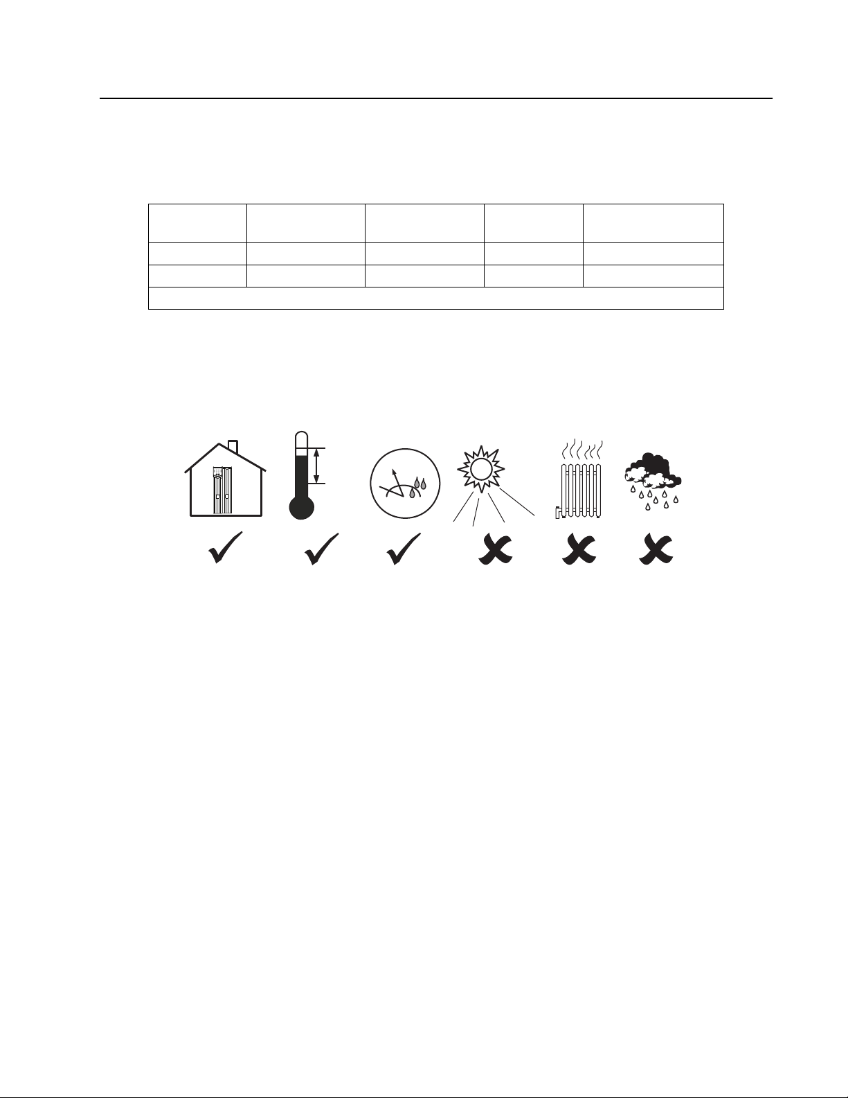
Receiving the Cabinet
Upon receipt, inspect the cabinet and contents for damage. Verify the contents are complete.
40°C
104°F
0°C
32°F
APC by Schneider Electric is not responsible for damage sustained during shipment of this product.
Report damage to the shipper immediately and contact APC by Schneider Electric at www.apc.com or
your APC by Schneider Electric reseller. Keep all packaging material for inspection if damage is found.
95%
0%
gen0902a
3NetShelter™ VX Seismic 42U Cabinet
Page 8
Configuration
CAUTION
TIP HAZARD
Secure the cabinet to the floor in its permanent location before loading equipment.
Failure to follow these instructions can result in injury or equipment damage.
NOTICE
IMPROPER AIRFLOW
Cover any empty vertical cabinet space with optional blanking panels (AR8101BLK for 19 in.
equipment mounting, not included).
Failure to follow these instructions can result in equipment damage.
Use blanking panels to maintain proper airflow. Improper airflow may damage installed
components.
Before installing your cabinet, plan the location of the equipment to be installed. Consider the space
needed by equipment and ergonomics of keyboards and video monitors.
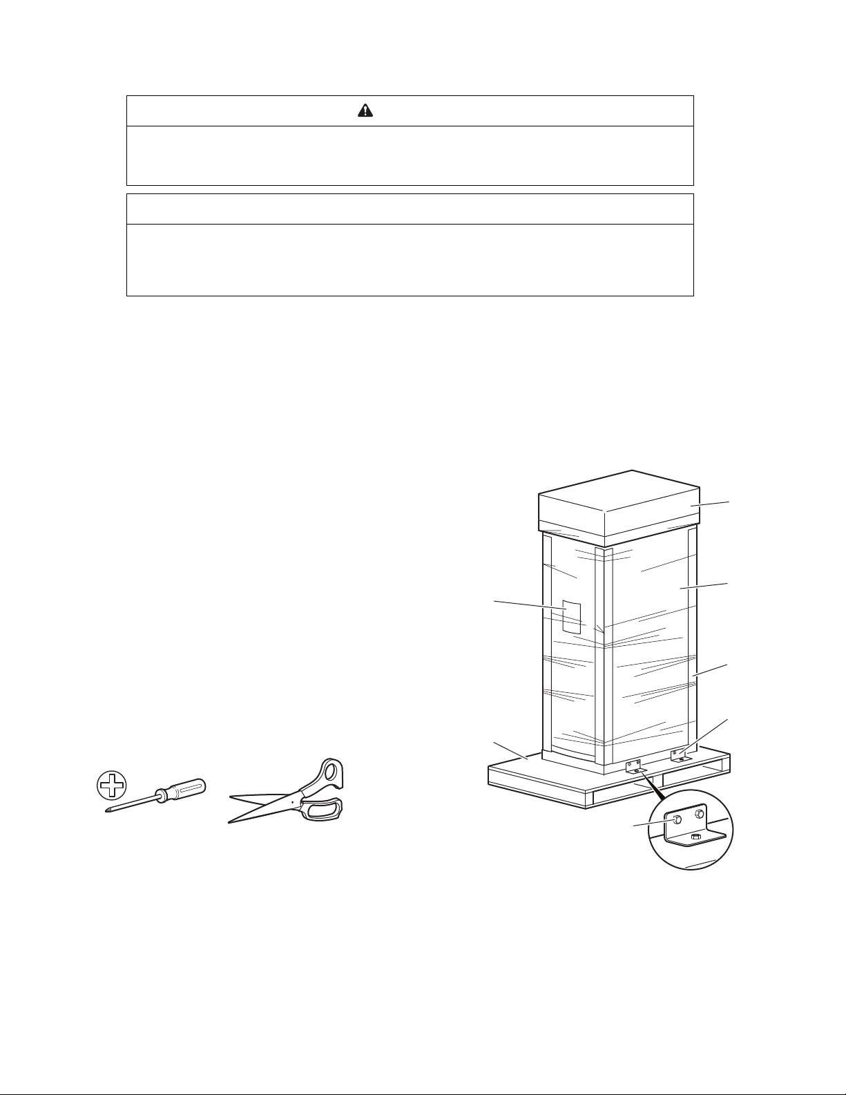
Unpack the Cabinet
Cabinet Packaging
Cardboard top cover
Stretch wrap
Cardboard corner
protectors
Pallet brackets
M8 bolts
Shipping pallet
Pouch containing the
13 mm/ 14 mm
open-ended wrench,
the user manual,
warranty card, and
literature
Tools Required (not provided)
NetShelter™ VX 42U Seismic Cabinet Installation4
ns0008a
Page 9

Please Recycle
The shipping materials are recyclable. Save them for later use, or dispose of them appropriately.
Disclaimer
APC by Schneider Electric is not responsible for damage sustained during reshipment of this product.
Take Inventory
After unpacking the cabinet, verify that all required components and hardware have been shipped with
the cabinet. See “Component Identification” on page 6 for a list of components. If any items are missing,
contact APC by Schneider Electric Customer Support at www.apc.com/support.
Unpacking Sequence
WARNING
WEIGHT/TIP HAZARD
• Use at least three people to unpack and assemble the cabinet.
• Secure the cabinet to the floor before installing the components.
• Do NOT extend more than one component from a populated cabinet at a time.
• Load the heaviest components first and place them toward the bottom of the cabinet.
Failure to follow these instructions can result in death, serious injury, or equipment damage.
Move the shipping pallet to a firm, level surface in an open area. Inspect the cabinet for visible signs of
shipping damage. Report damage immediately to the shipping company and contact APC by Schneider
Electric Customer Support at the number listed on the yellow sticker on the front of the cabinet.
1. Remove the open-ended wrench from the pouch on the front of the packaging.
2. Refer to the label on the packaging to determine where to cut the wrapping. Using heavy-duty
shears or a utility knife, carefully remove the plastic stretch-wrap surrounding the cabinet.
3. Remove the cardboard cover and the four cardboard corner protectors.
4. Remove the four brackets anchoring the cabinet to the shipping pallet. Use the 13 mm end of the
open-ended wrench, obtained in step 1, to remove the M8 bolts securing the brackets to the
pallet.
5. With one person on each side of the cabinet, carefully slide it toward the rear of the pallet. The
pallet will tip as it is moved to the rear of the pallet. Continue to slide the cabinet rearward until
the rear edge makes contact with the floor.
6. While two people carefully tip the cabinet slightly away from the pallet, have the third person pull
the pallet away from the cabinet.
NOTE: Save the pallet, mounting brackets, and bolts if you plan to reship the cabinet.
5NetShelter™ VX Seismic 42U Cabinet
Page 10
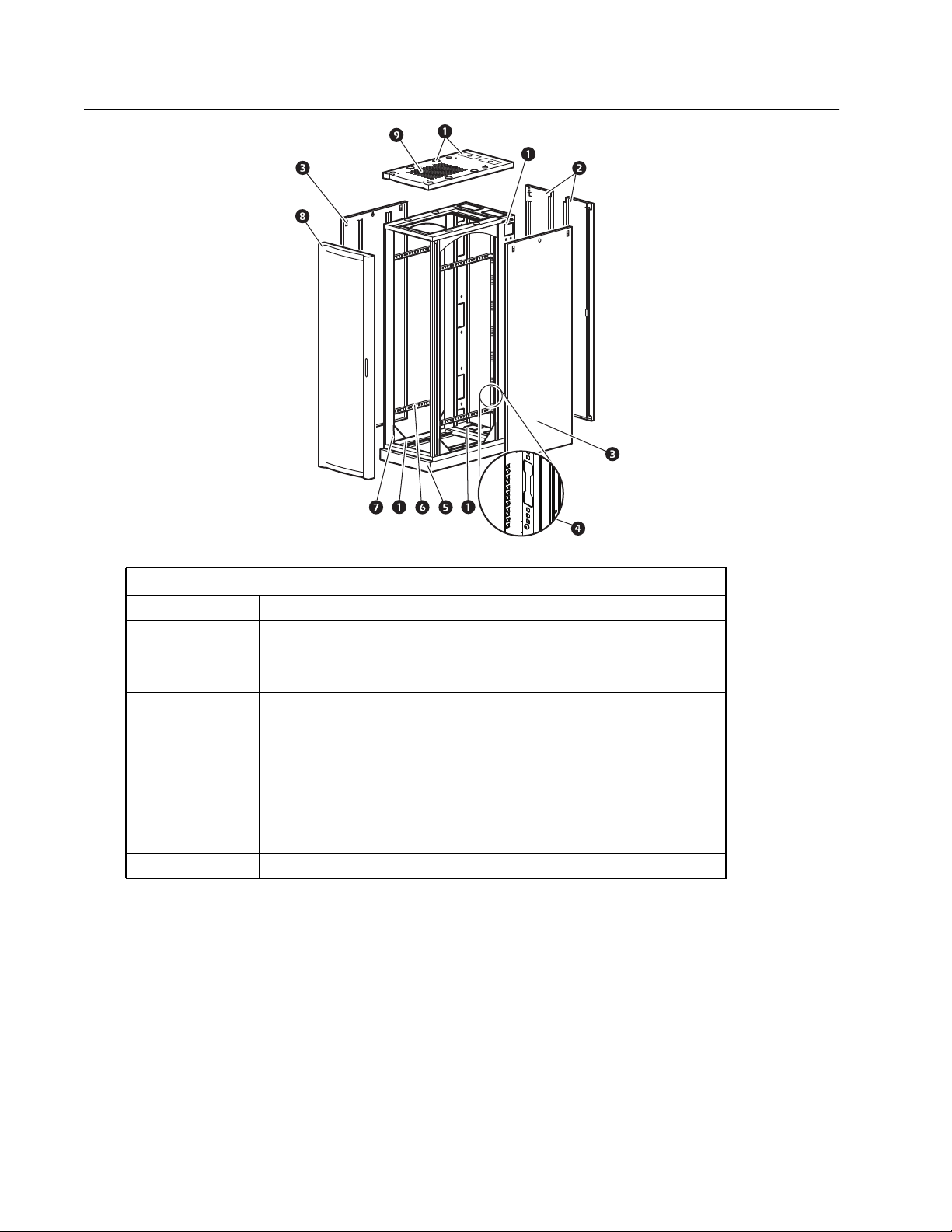
Component Identification
Features
Cable access Access on roof, sides, and base
• Ventilated split rear door for added access in narrow aisles
Doors
Side panels Side panels with locks (AR2144BLK only)
Frame
Roof Ventilated roof
• Quick-release, ventilated, reversible front door
• Front and rear door locks
• 42 U (73.5 in.) of storage height for 19 in. rack-mount equipment
• Adjustable vertical mounting rails
and horizontal braces
• Front and rear skirt
• Frame posts
• Ground studs on all panels and main structure
NetShelter™ VX 42U Seismic Cabinet Installation6
Page 11

Hardware
Item AR2144BLK AR2145BLK
Mounting hardware
M6 × 16 mm Phillips/slotted screws 60 60
Cage nut installation tool 1 1
M6 cage nuts 60 60
Plastic cup washers 60 60
Open-ended wrench
(13 mm/14 mm)
M5 Allen wrench 1 1
Door/side panel keys 2 2
Grommets/covers (included in bag)
4 × 4" grommets 2 4
4 × 8" grommets 3 6
4 × 4" cover 4 4
1 1
Location of keys and Mounting Hardware
1. The keys are inside the cabinet, fastened to the front left, vertical,
side-facing mounting rail.
2. The bag containing the mounting hardware is fastened to the floor of the
cabinet.
7NetShelter™ VX Seismic 42U Cabinet
Page 12

Cabinet Installation
WARNING
WEIGHT/TIP HAZARD
• Use only qualified personnel to install the cabinet.
• Use at least three people to unpack and assemble the cabinet.
• Secure the cabinet to the floor in its permanent location before loading equipment.
• Secure the cabinet to the floor before installing the components.
Failure to follow these instructions can result in death, serious injury, or equipment damage.
Secure the Cabinet
For seismic stability, the NetShelter VX Seismic Cabinet must be bolted to the floor. Install proper
anchoring hardware before starting this procedure.
Tools and Hardware Required.
Qty Item
4 Bolt plates (included)
8 M12 or ½ in. bolts (not included)
1 Adjustable wrench (not included)
1 Torque wrench (not included)
Bolt the Cabinet to the floor.
1. Remove the front and rear skirts on
the cabinet. (See“Remove the
Skirts” on page 21.)
2. Insert two bolts through each plate
and the holes in the plinth, using
the bolt plate (included). Screw the
bolts into the pre-installed
anchoring hardware in the floor.
3. Tighten the bolts to 60 lb-ft (81 N•m)
using a torque wrench.
ns0282b
NetShelter™ VX 42U Seismic Cabinet Installation8
Page 13

Grounding the Cabinet
HAZARD OF ELECTRIC SHOCK
Use a digital multimeter or continuity testing device to ensure all metal parts are properly bonded and
are at the same potential.
Failure to follow these instructions will result in death or serious injury.
DANGER
There are 22 M6 grounding studs on the
cabinet, located on the doors, the roof, the side
panels, and the frame.
It is recommended that you ground the side
panels, ceiling, and doors to the cabinet frame
and connect the cabinet to the data center
ground. Use a bonding kit with 12 AWG wire
and ring connectors. Insert paint-piercing
washers between grounding studs, connectors,
and nuts.
# of
studs
Location
12 Base
1 Rear cabling channel
1 Roof
2 Front door
4 Rear doors
2 Side panels (AR2144BLK only)
about
30 cm (13 in)
Top View
ns0135b
9NetShelter™ VX Seismic 42U Cabinet
Page 14

about
30 cm (13 in)
ns0136b
about
33 cm (13 in)
ns0138b
NetShelter™ VX 42U Seismic Cabinet Installation10
Page 15

ns0137b
11NetShelter™ VX Seismic 42U Cabinet
Page 16

ns0139b
ns0141b
NetShelter™ VX 42U Seismic Cabinet Installation12
Page 17

Side Panels
HEAVY EQUIPMENT
The panels are heavy. Have one person support the side panel while another releases the side
panel from its frame.
Failure to follow these instructions can result in injury or equipment damage.
Remove
Remove the side panels for access to the interior.
1. Use the key to lock the panel, if necessary.
2. Unscrew all four screws holding the panel,
starting from the bottom and working up.
3. Use the key to unlock the panel.
CAUTION
4. Tip the top of the panel away from
the cabinet.
5. Lift the panel up and off the
narrow horizontal lip at the bottom
of the cabinet frame.
ns0283a
ns0285a
13NetShelter™ VX Seismic 42U Cabinet
Page 18

Install
1. Engage the bottom of the panel securely
with the lip before pushing the top of the
panel forward into place.
2. Use the key to lock the panel.
3. Replace the screws, working from top to
bottom.
NOTE: When installing the side panels on an
extension cabinet, be sure to remove the plastic
grommets from the rear, side-facing, cableaccess openings on the rear cabling channel.
Remove the Roof
To remove the roof from the cabinet, remove the
four hex-head screws from the inside corners.
Use the 5 mm hex wrench (provided).
ns0166a
ns0043b
NetShelter™ VX 42U Seismic Cabinet Installation14
Page 19

Reverse the Front Door
You can reverse or remove the front door to
accommodate your site configuration. This section
shows how to remove and reverse the door on your
cabinet.
1. Remove both side panels. See “Remove” on
page 13.
2. Remove the two Phillips screws from the rear
of the door handle assembly and remove the
handle assembly from the door.
3. Rotate the door handle assembly 180° and
reinstall it, using the hardware removed in
step 2.
ns0176a
CAUTION
HEAVY EQUIPMENT
At least two people are required to perform this task. Have one person support the door
while another removes the door from its frame.
Failure to follow these instructions can result in injury or equipment damage.
4. Open the door and pull down on
the spring-loaded hinge pin
attached to the top of the door. Lift
the door from its frame and set it
safely aside.
ns0311a
15NetShelter™ VX Seismic 42U Cabinet
Page 20

Remove the Hinge Pin, Bumper, and Latch Brackets
NOTE: Remember the location of
and distance between all items
being removed. You will need to
duplicate this positioning when
reinstalling.
Use a Phillips head screwdriver
(not included) to remove the
hinge pin brackets , bumper
brackets , and latch bracket
from the cabinet frame.
ns0312a
NetShelter™ VX 42U Seismic Cabinet Installation16
Page 21

Install the Hinge Pin Brackets
Install the hinge pin brackets on the opposite side of the cabinet.
a. Remove the small plastic plugs covering the
insertion holes in the base and the top of the cabinet
frame. Reinstall them in the holes on the opposite
side of the cabinet.
b. Relocate the two hinge pin brackets from their
original position to their new position . Secure
by tightening the screws.
ns0313a
Install the Latch Plate and Bumpers
Relocate the latch bracket and the two door bumper brackets from
their original position to their new position .
NOTE: Be sure to maintain the original spacing between the
latch plate and bumpers, as well as their vertical relationship
with the cabinet frame.
ns0314a
17NetShelter™ VX Seismic 42U Cabinet
Page 22

Install the Door Assembly
HEAVY EQUIPMENT
Have one person support the door while another person places the door in its frame.
Failure to follow these instructions can result in injury or equipment damage.
1. Loosely tighten the hinge pin brackets.
2. Reinstall the door assembly.
a. Align the lower door hinge pin with the hole in the bottom of the hinge pin bracket and slide
the hinge pin into the hole.
b. Pull down the upper hinge pin.
c. Align the upper hinge pin with hole in the upper hinge pin bracket and release the hinge pin
into the hole.
d. Make sure that the door opens and closes properly.
3. Firmly tighten the countersunk screws to secure the hinge
pin brackets to the cabinet frame.
If using the Base model, reinstall the side panels.
CAUTION
NetShelter™ VX 42U Seismic Cabinet Installation18
Page 23

Equipment Installation
7
WARNING
WEIGHT/TIP HAZARD
• Secure the cabinet to the floor in its permanent location before loading equipment.
• Secure the cabinet to the floor before installing the components.
• Load the heaviest components first and place them toward the bottom of the cabinet.
Failure to follow these instructions can result in death, serious injury, or equipment damage.
NOTE: NetShelter VX cabinets are intended for use with listed equipment. If you install anything other
than listed equipment, fully evaluate the safety of your configuration.
This section provides general information on installing rack-mount equipment in the cabinet. Read the
documentation provided with the equipment you are installing for more specific instructions.
How to Identify a U space on a Mounting Rail or Frame Post
One U space consists of three square holes. Each U space, or position, is marked
with a number and separated by horizontal lines.
1U
6
5
ns0014a
19NetShelter™ VX Seismic 42U Cabinet
Page 24

Cage Nuts
If needed, APC by Schneider Electric offers a cage nut hardware kit (AR8100) for use with square holes.
CAUTION
FALLING EQUIPMENT HAZARD
Do NOT install cage nuts vertically with the ears engaging the top and bottom of the square hole.
Failure to follow these instructions can result in minor or moderate injury.
• Install cage nuts horizontally, with the ears engaging
the sides of the square hole.
• Install the cage nuts on the interior of the vertical
mounting rail.
Installation
1. From inside of the cabinet, insert the cage nut into the
square hole. Hook one ear of the cage nut assembly
through the far side of the hole.
2. Place the cage nut tool on the other side of the cage nut
and pull to snap into position.
ns1768a
Removal
1. Remove any attached screw.
2. Grasp the cage nut and squeeze the sides to release it
from the square hole.
gen0188a
NetShelter™ VX 42U Seismic Cabinet Installation20
Page 25

Cable Management
Cable Access Openings
There are cable access openings in
the roof , sides , and base of
the cabinet. The rear cabling
channel on the back of the cabinet
provides clearance for wiring
between the doors and the mounting
rails. it is recommended to use the
clearance between the rear
mounting rails and rear door for
routing data and power cables —
data on one side, and power on the
other side.
Before routing wires through the side
access holes on the cabinet with
side panels, ensure the protective
grommets (included) are installed
into the cable access openings.
Remove the Skirts
For additional cable access, you can
remove the skirts at the front and rear of
the cabinet by removing the two
countersunk screws in each skirt.
ns0338a
21NetShelter™ VX Seismic 42U Cabinet
Page 26

Vertical Mounting Rails
The vertical mounting rails are factory-installed in the proper position for use with rack-mountable
equipment that has a depth of 29.13 in. (740 mm). You can adjust the rails to the front or rear a total of
2.35 in. (60 mm) to accommodate different rails or equipment with various depths. The following sections
describe the procedures for adjusting the position of the mounting rails and for moving them within the
cabinet.
Mounting Rail Screws
The location of the screws that govern the position of the mounting rails is shown below.
Adjust the Mounting Rails
FALLING EQUIPMENT
NEVER perform this procedure with equipment installed on the vertical mounting rails.
Failure to follow these instructions can result in injury or equipment damage.
1. Use the 5 mm Allen wrench (included) to remove the socket-head screws from the hole in the
vertical mounting rail.
2. Slide the vertical mounting rail forward or rearward as desired. Insert the screws into the
appropriate holes. Tighten each screw.
CAUTION
2.35 in.
(60 mm)
ns0287a
NetShelter™ VX 42U Seismic Cabinet Installation22
Page 27

Horizontal Braces
Each side of the enclosure has adjustable
horizontal braces between the vertical frame
posts to support the vertical mounting rails and
manage cables.
Move a Brace
1. Use the 5 mm hex wrench (provided) to
remove the four hex-head screws that
hold the brace to the frame posts.
2. Locate the new position for the brace
and secure the brace to the frame
posts.
3. Place the brace at the new position.
Insert a socket-head screw through the
brace and frame post and tighten.
23NetShelter™ VX Seismic 42U Cabinet
Page 28

Specifications
AR2144BLK AR2145BLK
Item Measurement
Height 81.5 in. (207 cm)
Width 23.5 in. (59.6 cm) 23.0 in. (58.5 cm)
Depth 42.2 in. (107.4 cm)
Net weight 545 lb (162.8 kg) 458 lb (127.9 kg)
Ventilation (front door) 1384 in.² (8929 cm²)
Ventilation (rear door) 791.3 in.² (5105.5 cm²)
Ventilation (roof) 156 in.² (1006 cm²)
Clearance (for wiring between front door and
vertical rail)
3.27 in. (8.31 cm)
NetShelter™ VX 42U Seismic Cabinet Installation24
Page 29

Five-Year Factory Warranty
The limited warranty provided by APC by Schneider Electric in this Statement of Limited Factory
Warranty applies only to products you purchase for your commercial or industrial use in the ordinary
course of your business.
Terms of warranty
APC by Schneider Electric warrants its products to be free from defects in materials and workmanship
for a period of five years from the date of purchase. The obligation of APC by Schneider Electric under
this warranty is limited to repairing or replacing, at its sole discretion, any such defective products. This
warranty does not apply to equipment that has been damaged by accident, negligence, or misapplication
or has been altered or modified in any way. Repair or replacement of a defective product or part thereof
does not extend the original warranty period. Any parts furnished under this warranty may be new or
factory- remanufactured.
Non-transferable warranty
This warranty extends only to the original purchaser who must have properly registered the product. The
product may be registered at the APC by Schneider Electric Web site, www.apc.com.
Exclusions
APC by Schneider Electric shall not be liable under the warranty if its testing and examination disclose
that the alleged defect in the product does not exist or was caused by end user’s or any third person’s
misuse, negligence, improper installation or testing. Further, APC by Schneider Electric shall not be
liable under the warranty for unauthorized attempts to repair or modify wrong or inadequate electrical
voltage or connection, inappropriate on-site operation conditions, corrosive atmosphere, repair,
installation, start-up by non-APC by Schneider Electric designated personnel, a change in location or
operating use, exposure to the elements, Acts of God, fire, theft, or installation contrary to APC by
Schneider Electric recommendations or specifications or in any event if the APC by Schneider Electric
serial number has been altered, defaced, or removed, or any other cause beyond the range of the
intended use.
THERE ARE NO WARRANTIES, EXPRESS OR IMPLIED, BY OPERATION OF LAW OR
OTHERWISE, OF PRODUCTS SOLD, SERVICED OR FURNISHED UNDER THIS AGREEMENT OR
IN CONNECTION HEREWITH. APC BY SCHNEIDER ELECTRIC DISCLAIMS ALL IMPLIED
WARRANTIES OF MERCHANTABILITY, SATISFACTION AND FITNESS FOR A PARTICULAR
PURPOSE. APC BY SCHNEIDER ELECTRIC EXPRESS WARRANTIES WILL NOT BE ENLARGED,
DIMINISHED, OR AFFECTED BY AND NO OBLIGATION OR LIABILITY WILL ARISE OUT OF, APC
BY SCHNEIDER ELECTRIC RENDERING OF TECHNICAL OR OTHER ADVICE OR SERVICE IN
CONNECTION WITH THE PRODUCTS. THE FOREGOING WARRANTIES AND REMEDIES ARE
EXCLUSIVE AND IN LIEU OF ALL OTHER WARRANTIES AND REMEDIES. THE WARRANTIES
SET FORTH ABOVE CONSTITUTE APC BY SCHNEIDER ELECTRIC’S SOLE LIABILITY AND
PURCHASER'S EXCLUSIVE REMEDY FOR ANY BREACH OF SUCH WARRANTIES. APC BY
SCHNEIDER ELECTRIC WARRANTIES EXTEND ONLY TO PURCHASER AND ARE NOT
EXTENDED TO ANY THIRD PARTIES.
IN NO EVENT SHALL APC BY SCHNEIDER ELECTRIC, ITS OFFICERS, DIRECTORS, AFFILIATES
OR EMPLOYEES BE LIABLE FOR ANY FORM OF INDIRECT, SPECIAL, CONSEQUENTIAL OR
PUNITIVE DAMAGES, ARISING OUT OF THE USE, SERVICE OR INSTALLATION, OF THE
PRODUCTS, WHETHER SUCH DAMAGES ARISE IN CONTRACT OR TORT, IRRESPECTIVE OF
FAULT, NEGLIGENCE OR STRICT LIABILITY OR WHETHER APC BY SCHNEIDER ELECTRIC HAS
BEEN ADVISED IN ADVANCE OF THE POSSIBLY OF SUCH DAMAGES. SPECIFICALLY, APC BY
SCHNEIDER ELECTRIC IS NOT LIABLE FOR ANY COSTS, SUCH AS LOST PROFITS OR
REVENUE, LOSS OF EQUIPMENT, LOSS OF USE OF EQUIPMENT, LOSS OF SOFTWARE, LOSS
OF DATA, COSTS OF SUBSTITUENTS, CLAIMS BY THIRD PARTIES, OR OTHERWISE.
25NetShelter™ VX Seismic 42U Cabinet
Page 30

NO SALESMAN, EMPLOYEE OR AGENT OF APC BY SCHNEIDER ELECTRIC IS AUTHORIZED TO
ADD TO OR VARY THE TERMS OF THIS WARRANTY. WARRANTY TERMS MAY BE MODIFIED, IF
AT ALL, ONLY IN WRITING SIGNED BY AN APC BY SCHNEIDER ELECTRIC OFFICER AND
LEGAL DEPARTMENT.
Warranty claims
Customers with warranty claims issues may access the APC by Schneider Electric customer support
network through the Support page of the APC by Schneider Electric Web site, www.apc.com/support.
Select your country from the country selection pull-down menu at the top of the Web page. Select the
Support tab to obtain contact information for customer support in your region.
NetShelter™ VX 42U Seismic Cabinet Installation26
Page 31

Page 32

Worldwide Customer Support
Customer support for this product is available at www.apc.com.
© 2020 APC by Schneider Electric. NetShelter, APC, and the APC logo are trademarks owned by
Schneider Electric SE or its subsidiaries. All other trademarks may be property of their respective
owners.
990-1145B-001
6/2020
 Loading...