

Page 1

Operation
Smart-UPS® VT
10-40 kVA – 400 V
10-30 kVA – 208 V
10-30 kVA – 200 V
Page 2

Page 3

About this Manual
IMPORTANT SAFETY INSTRUCTIONS
SAVE THESE INSTRUCTIONS
This manual is intended for the user of the Smart-UPS
®
VT.
It refers to important saf ety warnings and instructions, gives an introduction to the display interface,
and provides information on operation, load connection, parts replacement, troubleshooting, total
power off and restart.
Only graphics of Smart-UPS
manual is intended for the us ers of one or more units within the
Note
®
VT with built-in batteries are shown in this manual, but the
Smart-UPS® VT family range.
:
Companion manuals
For additional information about:
®
Smart-UPS
VT 400 V:
• Safety – 990-2822
• Receiving and Unpacking – 990-2284
• Receiving and Unpacking (with batteries) – 990-1747
• Installation – 990-2283
• Installation (with batteries) – 990-1598
• Installation (in parallel) – 990-3045
• Installation (MBP CAN I/O Board) – 990-2873
®
Smart-UPS
VT 208 V:
• Safety – 990-2822
• Receiving and Unpacking (with batteries) – 990-1747
• Installation – 990-2869
• Installation (in parallel) – 990-3045
• Installation (MBP CAN I/O Board) – 990-2873A
®
Smart-UPS
VT 200 V:
• Safety – 990-2822
• Receiving and Unpacking – 990-2358
• Installation – 990-2360
• Installation (in parallel) – 990-3045
• Installation (MBP - CAN I/O Board) – 990-2873
1 Smart-UPS® VT 10-40 kVA, 400 V, 20 8 V, 200 V - O peration 990-2282A-001
Page 4

About this Manual
How to find updates to this manual
You can check for updates to this manual on the APC Web site (www.apc.com).
2 Smart-UPS® VT 10-40 kVA, 400 V, 20 8 V, 200 V - O peration 990-2282A-001
Page 5

Contents
Safety................................................................................1
Overview...........................................................................2
User Interface. . . . . . . . . . . . . . . . . . . . . . . . . . . . . . . . . . . . . . . . . . . . .2
Interface area . . . . . . . . . . . . . . . . . . . . . . . . . . . . . . . . . . 2
Display interface . . . . . . . . . . . . . . . . . . . . . . . . . . . . . . . . 2
Menu tree . . . . . . . . . . . . . . . . . . . . . . . . . . . . . . . . . . . . . 4
Operation..........................................................................6
Operation Modes. . . . . . . . . . . . . . . . . . . . . . . . . . . . . . . . . . . . . . . . . .6
Normal operation . . . . . . . . . . . . . . . . . . . . . . . . . . . . . . . . 6
Battery operation . . . . . . . . . . . . . . . . . . . . . . . . . . . . . . . . 6
Internal bypass operation . . . . . . . . . . . . . . . . . . . . . . . . . . 6
External maintenance bypass operation . . . . . . . . . . . . . . . . . 6
Optional parallel operation . . . . . . . . . . . . . . . . . . . . . . . . . 6
Operation Procedures. . . . . . . . . . . . . . . . . . . . . . . . . . . . . . . . . . . . . .7
How to turn into bypass . . . . . . . . . . . . . . . . . . . . . . . . . . . 7
How to turn into normal operation . . . . . . . . . . . . . . . . . . . 10
How to turn load OFF/ON via the display interface . . . . . . . . . 12
How to view the Status screens . . . . . . . . . . . . . . . . . . . . . 12
How to view Logging and Statistics . . . . . . . . . . . . . . . . . . . 14
How to use the Diags screen . . . . . . . . . . . . . . . . . . . . . . . 15
How to perform a total power off . . . . . . . . . . . . . . . . . . . . . 16
How to perform a restart . . . . . . . . . . . . . . . . . . . . . . . . . . 19
Configuration.................................................................22
Settings . . . . . . . . . . . . . . . . . . . . . . . . . . . . . . . . . . . . . . . . . . . . . . . .22
How to change the Clock and the Alarms in the Setting menu . 22
How to change the Beeper setup, the Contrast, and the
Language in the Display menu
. . . . . . . . . . . . . . . . . . . . . . 23
990-2282A-001 Smart-UPS® VT 10-40 kVA, 400 V, 208 V, 200 V – Operation i
Page 6

Maintenance...................................................................25
Parts Replacement . . . . . . . . . . . . . . . . . . . . . . . . . . . . . . . . . . . . . . . 25
How to determine if you need a replacement part . . . . . . . . . 25
How to return parts to APC . . . . . . . . . . . . . . . . . . . . . . . . 25
How to store the battery modules . . . . . . . . . . . . . . . . . . . . 26
How to replace a Network Management Card . . . . . . . . . . . . 28
How to replace and install a battery module . . . . . . . . . . . . . 28
Troubleshooting............................................................33
Status and Alarm Messages . . . . . . . . . . . . . . . . . . . . . . . . . . . . . . . 33
Display messages . . . . . . . . . . . . . . . . . . . . . . . . . . . . . . 33
ii Smart-UPS® VT 10-40 kVA, 400 V, 208 V, 200 V – Operation 990-2282A-001
Page 7

Safety
All safety instructions in the Safety Sheet (990-2822) shall be read, understood,
and followed prior to handling/using the system. Failure to do so could result in
Warning
For safety reasons, the trained user is only allowed to operate the display and replace the following
components:
• Network Management Card with temperature sensor (training necessary)
• Battery M odule (training necessary)
equipment damage, serious injury, or death.
990-2282A-001 Smart-UPS® VT 10-40 kVA 400V, 208V, 200V – Operation 1
Page 8
Overview
Overview Screen
User Interface
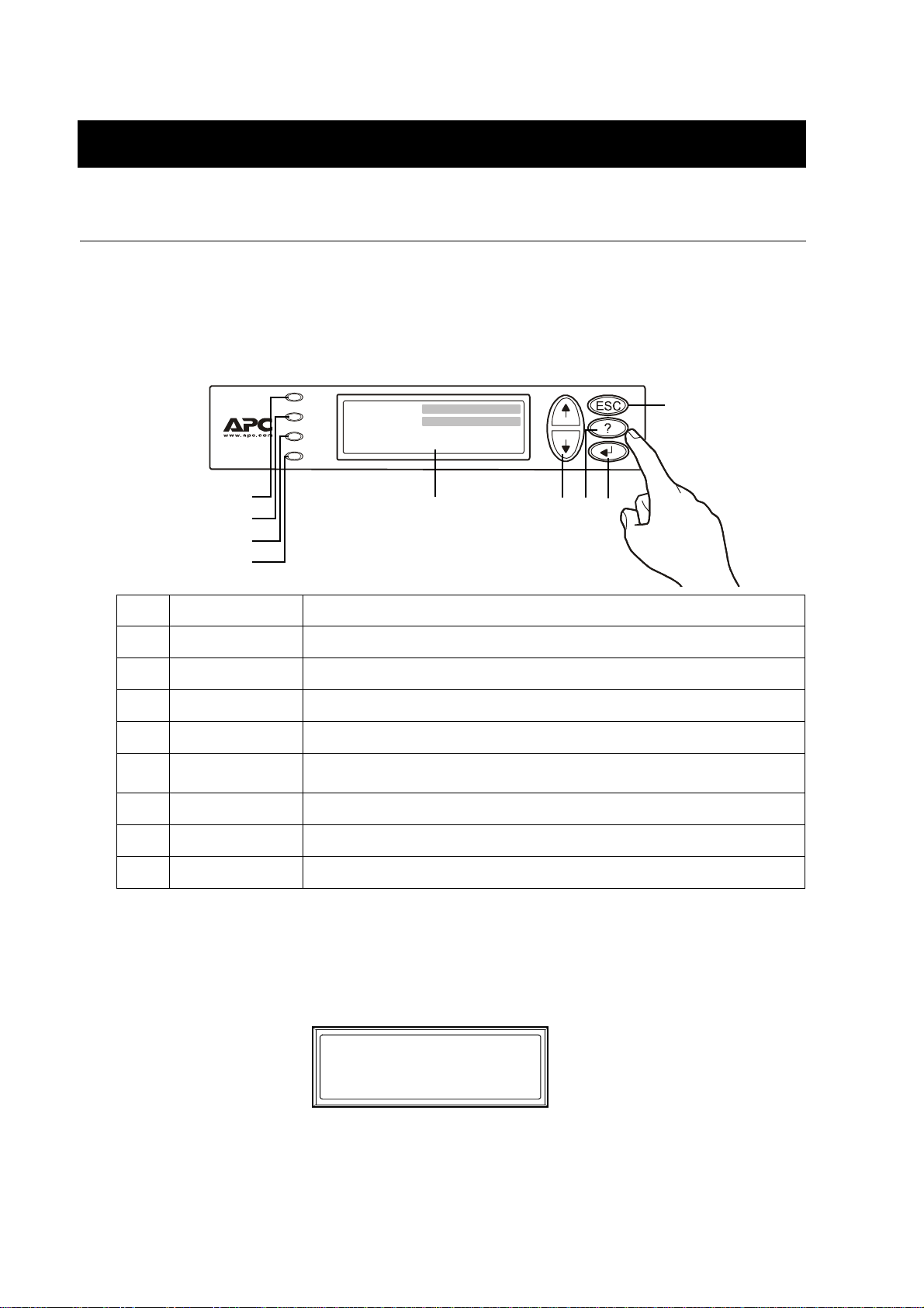
Interface area
The four LEDs to the left of the display indicate the operational status of the UPS. The five
navigation keys to the right are used to select and open menu items, to access information, change
system parameters, and to get context-sensitive h elp.
LOAD ON
Chrg 100%
ON BATT
Load 000%
230Vin 000Vout 50Hz
BYPASS
Run-time: 00hr 30m
FAULT
LOAD ON When the green LED is lit, the UPS provides power to the load equipment.
ON BATT
BYPASS
FAULT
LCD SCREEN
UP AND DOWN
NAVIGATION KEYS
HELP KEY
ENTER KEY
ESC KEY
Display interface
When the yellow LED is lit, power flows from the batteries to the load.
When the yellow LED is lit, power to the load is supplied through bypass.
When the red LED is lit, a fault condition exists.
Displays alarms, status data, instructional help, and configuration items.
Used to scroll through and select menu items.
Opens context-sensitive help.
Opens menu items and confirms changes to system parameters.
Returns to previous screen displayed.
Overview Screen (LCD screen). The Overview Screen is the main entrance to the user functions
of the display interface.
Chrg 100%
Load 000%
230Vin 000Vout 50Hz
Runtime: 0hr 0m
ENTER key takes you from the Overview Screen to the Main Menu Screen.
The
2 Smart-UPS® VT 10-40 kVA 400V, 208V, 200V – Operation 990-2282A-001
Page 9

Overview – User Interface
Main Menu Screen. From the Mai n Menu Scr een it is po ssibl e to co mmand, c onfigu re, and monit or th e
system through the sub menu screens: Control, Status, Setup, Logging, Display, Diags, and Help (see
the section Menu tree).
Main Menu Screen
The selector arrow is controlled
by the UP/DOWN keys. The arrow
marks the item you may open by
pressing ENTER.
Control
Status
Setup
Logging
Display
Diags
Help
990-2282A-001 Smart-UPS® VT 10-40 kVA 400V, 208V, 200V – Operation 3
Page 10
Overview – User Interface
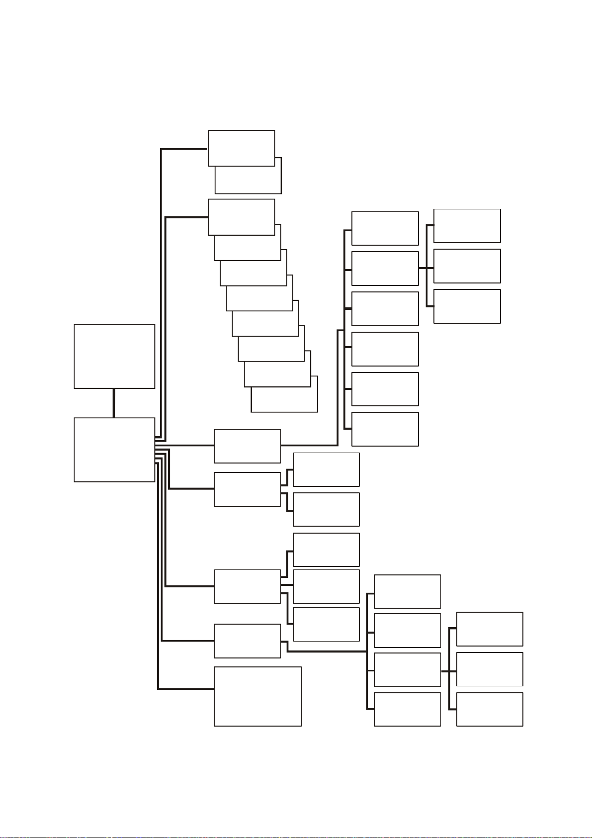
Menu tree
The menu tree provides a quick overview of the functions and views you can access.
If you get beyond the f unctions described in the menu tree, do not proc eed. Press ESC to go ba ck.
Overview
Screen
Chrg xxx%
Load xxx%
xxxVin
Runtime
Control
Status
Turn load
off/on
UPS into/out
of bypass
Vin Vbyp Vout
Iin lbyp Iout
kVA & kW
Frequencies
Load & Bat &
Temp
Batteries
Alarm
thresholds
Parallel status
Clock
Alarms
Shutdown
Default
System
Load
Runtime
Par.
redundancy
Control
Status
Setup
Logging
Main Menu
Screen
Display
Diags
Help
Setup
Logging
Display
Diags
Help
Settings
Logging
Display setup
Diagnostics
on any screen
& any line, press?
for context
sensitive help
View log
View statistics
Beeper setup
Contrast
Language
Other
Faults and
Diagnostics
System
Information
Switch
Status
Raw Status
Data
Int. mech
Byp SW
Q3 External
Byp SW
Status from
MBP
4 Smart-UPS® VT 10-40 kVA 400V, 208V, 200V – Operation 990-2282A-001
Page 11

Caution
Overview – User Interface
The display provides acce ss to mor e func tions than descr ibed in t his man ual. Th ose funct ions
should not be accessed without the assistance of APC Customer Support in order to avoid
unwanted load impacts. For APC World-Wide Customer Support, refer to the back cover of
this manual. If you by accident get beyond the functions described, press
ESC to return to
previous screens.
990-2282A-001 Smart-UPS® VT 10-40 kVA 400V, 208V, 200V – Operation 5
Page 12

Operation
Operation Modes
The UPS has different operation modes. If the installation includes a Maintenance Bypass Panel
(MBP), an external maintenance bypass operation mode will also be available.
Normal operation
The UPS converts utility/mains power to conditioned power for the connected load.
Battery operation
The UPS provides power to the connected load from its internal and (if available) external batteries
for a finite period. The UPS transf ers to batt ery operati on if the supply of uti lity/ma ins power fail s, or
is outside the pre-defined limits.
Internal bypass operation
Internal bypass keeps the load supplied with utility/mains power during maintenance of the UPS
power sections. In internal bypass operation, utility/mains power is sent directly to the connected
load bypassing all internal UPS functions and filters. Battery back-up is not available in internal
bypass operation even though the batteries are in place.
External maintenance bypass operation
The UPS can be connected to an optional external MBP. When activated, this panel bypasses the entire
UPS enclosure, feeding utility/mains power directly to the load. An activated external MBP
isolates the UPS and allows maintenance to be performed. An external MBP is mandatory if the UPS is
running in parallel.
Optional parallel operation
The connected load is powered by multiple UPS units to increase system redundancy or to increase
power. The internal mechanical bypass lever is not available.
completely
6 Smart-UPS® VT 10-40 kVA 400V, 208V, 200V – Operation 990-2282A-001
Page 13
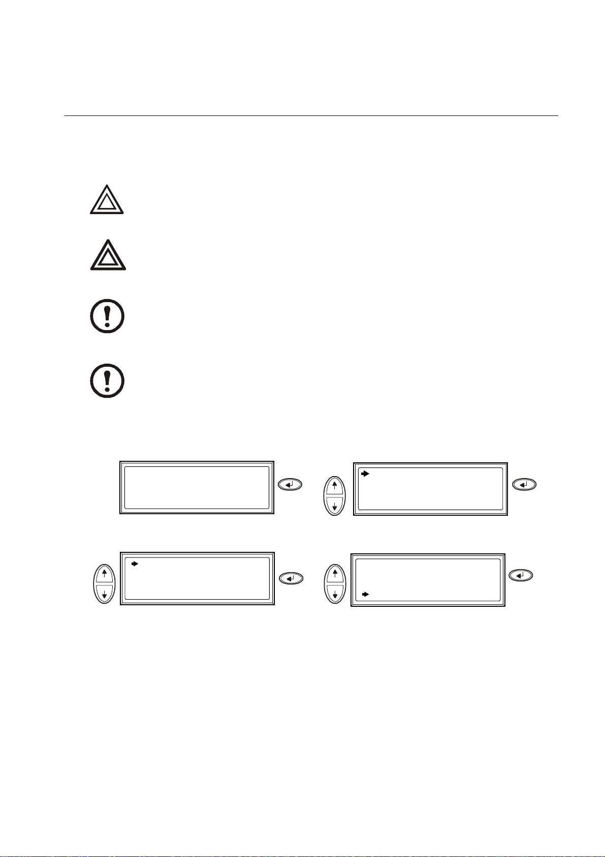
Operation Procedures
Use
How to turn into b y pass
Single System – turning into internal bypass.
The load is not protected by the UPS and the power is not conditioned when the internal
mechanical bypass lever is activated.
Caution
In bypass operati on the batteries are stil l charged. If a total power off is r equired, the batteries
must be pulled out to th e red di sconne ct lin e, see t he sect io n How to perf orm a tot al power off.
Warning
This procedure is not applicable to parallel systems as the internal mechanical bypass lever is
unavailable.
Note
If the UPS is running and controllable through the display, carry out ste ps 1 t h ro ugh 5. I f not ,
go directly to step 6.
Note
Chrg 100%
Load 000%
xxxVin 000Vout x0Hz
Runtime: 0hr 0m
Press
Use
Control
Status
Setup
Logging
Display
Diags
Help
Press
UPS into Bypass
Do Self Test
Simulate Power Fail
Start Runtime Cal
Check that the UPS is in bypass. The green
(LOAD ON) and the yellow (BYPASS) LEDs
are lit.
Press
Use Press
Confirm:
UPS into Bypass
NO, ABORT
YES, UPS into Bypass
Remove the Front Panel fr om the UPS (s ee
the Receiving and Unpacki ng shee t referred
to under the section Companion manuals).
990-2282A-001 Smart-UPS® VT 10-40 kVA 400V, 208V, 200V – Operation 7
Page 14
Operation – Operation Procedures
Use
Single System – turning into external bypass.
Turn the internal m echanical b ypass
lever upwards to activate it. The load
will now be supported directly by
utility/mains power.
Reinstall the Front Panel.
In bypass operation the batteries are still powered. If a total power off is required the batteries
must be pulled out to th e red di sconne ct lin e, see t he sect io n How to perf orm a tot al power off.
Warning
Chrg 100%
Load 000%
xxxVin 000Vout x0Hz
Runtime: 0hr 0m
Press
Use
Control
Status
Setup
Logging
Display
Diags
Help
Press
UPS into Bypass
Do Self Test
Simulate Power Fail
Start Runtime Cal
From the external MBP: Turn the bypass
switch
If the UPS has to be completely isolated/
(Q003) to position “1” (ON).
Press
Use
From the ex ternal MBP: Turn the output
switch (
Confirm:
UPS into Bypass
NO, ABORT
YES, UPS into Bypass
Q002) to position “0” (OFF).
Press
removed, see the section How to perform a
total power off.
8 Smart-UPS® VT 10-40 kVA 400V, 208V, 200V – Operation 990-2282A-001
Page 15

Operation – Operation Procedures
Use
Parallel Sy stem – turning into external bypass.
P
In bypass operati on the batteries are stil l charged. If a total power off is r equired, the batteries
must be pulled out to th e red di sconne ct lin e, see t he sect io n How to perf orm a tot al power off.
Warning
Chrg 100%
Load 000%
xxxVin 000Vout x0Hz
Runtime: 0hr 0m
Press
Use
Control
Status
Setup
Logging
Display
Diags
Help
Press
UPS into Bypass
Do Self Test
Simulate Power Fail
Start Runtime Cal
Press
Use
Confirm:
UPS into Bypass
NO, ABORT
YES, UPS into Bypass
Press
From the UPS: Check that all UPS units are i n
bypass on each of the displays.
From the external MBP: Turn the bypass
switch (
From the external MBP: Turn the output
isolation breaker (
From the external MBP: Check that all output
lamps are lit
From the external MBP: Turn all input
switches (
From the UPS: Disconnect the batteries by
Q003) to position “1” (ON).
Q004) to position “0” (OFF).
(Q002).
Q001) to position “0” (OFF).
pulling them out to the red disconnect line.
From the external MBP: Check that the bypass
lamp indication is lit
From the external MBP: Check that the lamp
(Q003).
indication of the output isolation breaker is lit
(Q004).
From the UPS: Turn OFF each UPS from the
display via Control
– Turn Load off – Yes,
Turn Load off.
From the external MBP: Turn all output
switches (
From the XR Enclosure(s) (if available): Set
Q002) to position “0” (OFF).
the DC disconnect swi tch (if available) to
position
From the XR Enclosure(s) (if available):
OFF.
Disconnect the batteries by pul ling them out to
the red disconnect line.
For a total UPS shut down see the section How
to perform a total power off.
990-2282A-001 Smart-UPS® VT 10-40 kVA 400V, 208V, 200V – Operation 9
Page 16

Operation – Operation Procedures
How to turn into norma l operation
Single System – turning into normal operation from internal bypass.
Never atte mpt to switch back the UPS into normal operation till you have verified that there
are no internal UPS faults.
Caution
Check that the UPS is in bypass. The green
(
LOAD ON) and the yellow (BYPASS) LEDs are
lit.
Press ESC to ret urn to t he previo us men us and
turn out of bypass from the display via
Control–UPS out of bypass–Yes, UPS out
Turn the mechanical bypass lever downwards
into a horizontal positio n to deactiva te the
internal bypass operat ion.
Check that the UPS is in normal operation.
The yellow (
green (
BYPASS) LED turns off and the
LOAD ON) LED remains lit.
of bypass.
Single System – turning into normal operation from external bypass.
Never atte mpt to switch back the UPS into normal operation till you have verified that there
are no internal UPS faults.
Caution
From the external MBP: Turn the output
switch (
Q002) to position “1”(ON).
From the UPS: Check that the yello w
(
BYPASS) LED is lit and the green (LOAD
ON
) LED is lit.
From the external MBP: Turn the bypass
switch (
From the UPS: Check that the UPS is in
normal operation. The yellow (
LED turns off and the green (
Q003) to position “0” (OFF).
BYPASS)
LOAD ON) LED
remains lit.
From the UPS: Turn out of bypass from the
display via Control–UPS out of bypass–
Yes, UPS out of bypass.
10 Smart-UPS® VT 10-40 kVA 400V, 208V, 200V – Operation 990-2282A-001
Page 17

Operation – Operation Procedures
Parallel System – turning into normal operation from ext e rnal bypass.
Never attempt to turn the UPS into normal operation till you have verified that there are no
internal UPS faults.
Caution
From the external MBP: Turn all input
switches (
From the external MBP: Turn all output
switches
Q001) to position “1” (ON).
(Q002) to position “1” (ON). The
lamp indicator of t he output isola tion breaker
(Q004) is still lit.
From the XR Enclosure(s) (if available): Set
the DC disconnect switch (if available) to the
ON position.
From the UPS: Turn ON all UPS units from
each display via Control–Turn Load ON–
Yes, Turn Load ON.
From the UPS: Turn the UPS units into
bypass from one UPS display via Control–
UPS into bypass–Yes, UPS into bypass.
Check that the UPS units are in bypass. The
green (
LOAD ON) and the yellow (BYPASS)
LEDs are lit.
From the external MBP: Check that all the
output lamps
From the UPS: Connect the batteries in the
(Q002) are lit.
UPS by pushing them in.
From the XR Enclosure(s) (if available):
Connect the batteries by pushing them in.
From the external MBP: Check that all the
lamps (
From the external M BP: Check t hat the lamp
Q002) are unlit.
indicator of the output isolation breaker is lit
(
Q004).
From the external MBP: Turn the output
isolation breaker (
Now the lamps
From the UPS: Turn the UPS units out of
Q004) to position “1” (ON).
(Q003 + Q004) ar e lit.
From the external MBP: Turn the bypass
switch (
lamps (
Q003) to position “0” (OFF). The
Q004) are unlit, but (Q003) is lit until
the UPS is running in normal operation.
bypass from the display via Control–UPS
out of bypass–Yes, UPS out of bypass.
990-2282A-001 Smart-UPS® VT 10-40 kVA 400V, 208V, 200V – Operation 11
Page 18

Operation – Operation Procedures
Use
Use
Use
Use
How to turn load OFF/ON via the display interface
Disconnecting the UPS out put to the load does NOT de-energi ze the UPS! Always fo llow
the total power off procedure if you need to de-energize the UPS in emergency
Warning
situation s, see sectio n How to perform a total power off!
Turn Load OFF – How to disconne ct the UPS outp ut to the load eq uipment.
Chrg 100%
Load 000%
xxxVin 000Vout x0Hz
Runtime: 0hr 0m
Press
Use
Control
Status
Setup
Turn Load Off
Press
Confirm:
Turn Load OFF
NO, Abort
YES, Turn Load OFF
Logging
Display
Diags
Help
Press
Press
If the UPS is r unning in parallel operation
this procedure must be carried out on each
UPS.
Turn load ON – How to connect the UPS output to the load equipment.
Chrg 100%
Load 000%
xxxVin 000Vout x0Hz
Runtime: 0hr 0m
Press
Use
Control
Status
Setup
Logging
Display
Diags
Help
Press
Turn Load On
If the UPS is r unning in parallel operation
Press
Confirm:
Turn Load OFF
NO, Abort
YES, Turn Load ON
Press
this procedure must be carried out on each
UPS.
12 Smart-UPS® VT 10-40 kVA 400V, 208V, 200V – Operation 990-2282A-001
Page 19

How to view the Status screens
Chrg 100%
Load 000%
xxxVin 000Vout x0Hz
Runtime: 0hr 0m
Use the UP/DOWN keys to go through the parameters:
View Parameters
Press
Use
Operation – Operation Procedures
Control
Status
Setup
Logging
Display
Diags
Help
Press
Voltage on all
phases
Current on all
phases
kVA and kW Apparent power (kVA) and real power (kW) generated by the UPS and the connected
Frequencies Utility/mains frequency, bypass frequency, and output frequency in Hertz (Hz).
Load and batteries Load: Percentage of the load in relation to the total UPS capacity.
Bat Voltage Shows either the positive or negative half of the battery voltage (the lower value of the
Bat Cap Percentage charge on the batteries in relation to the total battery capacity.
Batteries Bat AmpHr: Battery capacity, including both external and internal batteries.
Alarm thresholds Load: An alarm will be set when the load is above the threshold level.
Parallel Status Local UPS is slave/master:
Utility/mains voltage (V), bypass voltage (V), and output voltage (V) for each phase.
Utility/mains current (A), bypass current (A), and output current (A) for each phase.
load.
two will appear).
Runtime: The predicted runtime at the present load.
UPS Temp: The highest external battery temperature.
Runtime: An alarm will be set when the runtime is below the threshold level.
# of UPSs OK: Indicates the number of parallel UPS units that is OK.
# of UPSs fail: Indicates the number of parallel UPS that has failed.
Par load Status KVA and KW: Total apparent power (kVA) and real power (kW) generated by the
parallel UPS units and the connected load.
Par redundancy: n+1, an alarm will be set if the redundancy level is below the threshold
level.
Parallel Operation
Mode
Press the ESC key to return to the previous menus.
990-2282A-001 Smart-UPS® VT 10-40 kVA 400V, 208V, 200V – Operation 13
The parallel operation mode can be off, load on, requested bypass, i n by pass d ue to f a ult
or maintenance.
Page 20

Operation – Operation Procedures
Use
Use
How to view Logging and Statistics
The View Log. View the 100 most recent UPS log events, and view the logged deta ils of the even ts, such
as date, time of occurrence, and event number.
Chrg 100%
Load 000%
xxxVin 000Vout x0Hz
Runtime: 0hr 0m
Press
Use
Control
Status
Setup
Logging
Display
Diags
Help
View log
Clear log
View statistics
The top line states date, time, and event
Press
24-Sep 15:06:48 #15
Mains out of
On Line
===================
Range
Logging Screen (example)
number . Lines 2, 3, and 4 are part of the event
list. To view the entire list: Use the
UP/DOWN
keys to go through the log events and press
ENTER to get a detailed description of a
particular event.
Press
Press
The View Statistics. View the statistics on the operation mode changes, the inverter time, and the
duration of battery operation.
Chrg 100%
Load 000%
xxxVin 000Vout x0Hz
Runtime: 0hr 0m
Press
Use
Control
Status
Setup
Logging
Display
Diags
Help
Press
Use
View log
Clear log
View statistics
===================
Logging Screen
Press
14 Smart-UPS® VT 10-40 kVA 400V, 208V, 200V – Operation 990-2282A-001
Page 21

How to use the Diags screen
The Diags. View troubleshooting information.
Chrg 100%
Load 000%
xxxVin 000Vout x0Hz
Runtime: 0hr 0m
Use
Fault & Diagnostics
System Information
Switch status
Raw Status Dump
Diags Screen
Press
Press
Use
Operation – Operation Procedures
Control
Status
Setup
Logging
Display
Diags
Help
Press
Note
For more details on the Fault and Diagnostics screens, see the section Troubleshooting.
990-2282A-001 Smart-UPS® VT 10-40 kVA 400V, 208V, 200V – Operation 15
Page 22

Operation – Operation Procedures
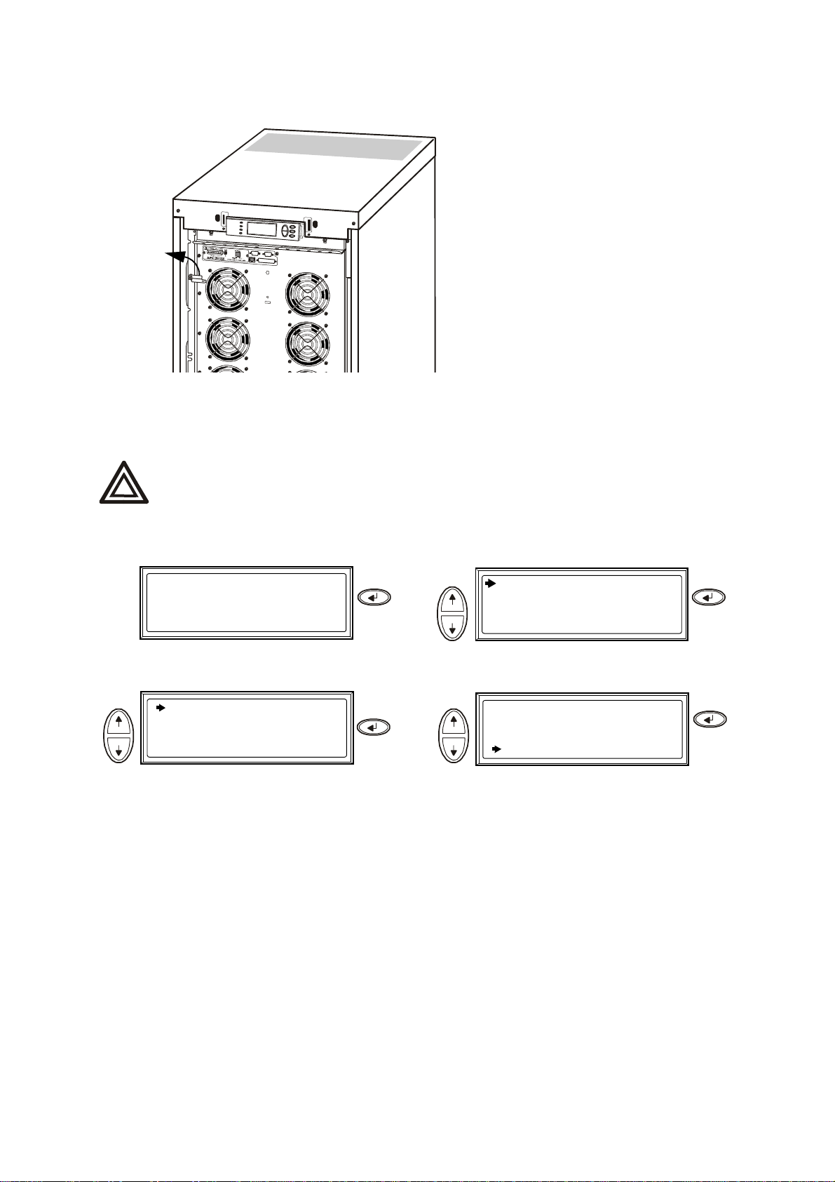
How to perform a total power off
Total power off – single system without MBP.
Mains
breaker
UPS
Check that the load is OFF.
From the XR Enclosure(s) (if available): Set
the DC disconnect switch to the
From the XR Enclosure(s) (if available):
XR Enclosure
OFF position.
Disconnect the batter ie s by pull ing th em out to
the red disconnect line shown on each battery
unit.
From the UPS: Turn OFF the UPS from the
display via Control–Turn Load Off –Yes,
Turn Load Off.
From the UPS: Disconnect the batteries by
pulling them out to the red disconnect line
shown on each battery unit.
Set the util ity/mains breaker to the OFF or
LOCKED-OUT position. If the UPS has dual
utility/mains supply, set both supplies to the
OFF or LOCKED-OUT position.
WARNING!
The lockout procedures at utility/mains breaker must be followed. If necessary, install a
Warning
16 Smart-UPS® VT 10-40 kVA 400V, 208V, 200V – Operation 990-2282A-001
padlock.
Page 23

For details on how to remove Battery L ocks (if avai lable) see the section How to remove
and install battery locks (if available).
Total power off – single system with MBP.
Operation – Operation Procedures
Check that the load is OFF.
From the external MBP: Turn the output
switch
From the XR Enclosure(s) (if available): Set
(Q002) to position “0” (OFF).
the DC disconnect switch (if available) on the
XR Enclosure(s) to th e
From the XR Enclosure(s) (if available):
OFF position.
Disconnect the batter ie s by pull ing th em out to
the red disconnect line.
Total power off – parallel system.
Check that the load is OFF.
From the UPS: Turn load OFF the UPS from
the display via Control–Turn Load off– Yes,
turn Load off.
From the external MBP: Turn the input switch
(Q001) to position “0” (OFF).
From the UPS: Disconnect the batteries in the
UPS by pulling them out to the red disconnect
line.
From the UPS: Turn load OFF each of the UPS
units from the display via Control–Turn
Load off–Yes, turn Load off.
From the external MBP: Turn the output
isolation breaker
From the external MBP: Turn all input
switches
From the UPS: Disconnect the batteries in the
(Q001) to position “0” (OFF).
(Q004) to position “0” (OFF).
UPS units by pulling them out to the red
disconnect line.
990-2282A-001 Smart-UPS® VT 10-40 kVA 400V, 208V, 200V – Operation 17
From the external MBP: Turn all output
switches
From the XR Enclosure(s) (if available) : Set
(Q002) to position “0” (OFF).
the DC disconnect switch (if available) to the
OFF position.
From the XR Enclosure(s) (if available) :
Disconnect the batteries on the UPS units by
pulling them out to the red disconnect line.
Page 24

Operation – Operation Procedures
Total power off – isolating one UPS in a parallel system.
From the UPS: From the Main Menu screen
select Status and scroll down to Status of
actual redundancy: n+ in order to check that
the remaining UPS(s) will be able to ca r ry the
load when one UPS is isolated.
From the external MBP: Check that the output
lamp
(Q002) of the U PS to be isolated is lit.
From the external MBP: Turn the input switch
(Q001) connected to the UPS you want to
isolate to position “0”
From the UPS: Disconnect the batteries in the
(OFF) .
UPS which you want to isolate by pull ing them
out to the red disconnect line.
From the UPS: T ur n l oad OFF from the display
on the UPS to be isolated via Control–Turn
Load off–Yes, turn Load off.
From the external MBP: Turn the output
switch
to isolate to position “0”
From the XR Enclosure(s) (if available): Set
(Q002) connected to the UPS you want
(OFF).
the DC disconnect switch (if available) on the
XR Enclosure to the
From the XR Enclosure(s) (if available):
OFF position.
Disconnect the batt erie s by pull ing the m out t o
the red disconnect line.
Parallel system – turning the isolated UPS into normal operation.
From the external MBP: Turn the input switch
(
Q1) connected to the UPS you want to turn
into normal operation to position “1”
From the XR Enclosure(s) (if available):
Connect the batteries by pulling them in.
(ON).
From the UPS: Connect the batteries by
pulling them in.
From the XR Enclosure(s) (if available): Set
the DC disconnect switch (if available) on the
XR Enclosure to position
From the external MBP: Turn the output
switch
(Q002) connected to the UPS you want
to turn into normal operation to position “I”
(ON).
From the UPS: Press ESC two tim es to get bac k
to the Overview Screen.
From the UPS: Turn load ON from the display
on the UPS you want to turn into normal
operation via Control–Turn Load on–Yes,
turn Load on.
From the UPS: On the Overview Sc reen, check
that the loa d percentage of the UPS units is
approximately the same.
ON.
18 Smart-UPS® VT 10-40 kVA 400V, 208V, 200V – Operation 990-2282A-001
Page 25

Operation – Operation Procedures
How to perform a restart
Restart – single system wihout external MBP.
Only trained personnel familiar with the construction and the equipment may
restart the UPS.
Warning
Set the utility/mains breaker to the ON position.
If your installation includes an XR Battery Enclosure (SUVTBXR2B6S/SUVTBXR6B6S) with a
DC disconnect switch, set the DC disconnect switch to the
ON position.
Wait approximately 30 seconds for the system to boot up and carry out a self test.
Note
After system boot-up, the display will automatically ask you to confirm/select voltage and frequency as
shown in the following.
Voltage conf irmation. At restart, the display will prompt you through the following screens:
Use
Confirm Voltage
Use 400V
Yes, use 400V
No, select another
Press
When the Confirm Voltage prompt appears on
the screen, go to the desired voltage using the
DOWN keys and press ENTER.
UP/
Use
Apply load?
Yes
No
When the prompt Apply load appears, go to Yes
using the
UP/DOWN keys and press ENTER if you
want the UPS to provide a load output now. (If
you do not want UPS load output at this point, go
to No).
Chrg xxx% ||||||||||
Load xxx% ||||||||||
xxx Vin xxxVout xxHz
Run-time: xxhr xxmin
The green (LOAD ON) LED is now lit . Press ESC
two times and the display will show the above
Overview Screen.
Press
The UPS is now ready to support the load.
Note
990-2282A-001 Smart-UPS® VT 10-40 kVA 400V, 208V, 200V – Operation 19
Page 26

Operation – Operation Procedures
Auto-detection on frequency – if a problem occurs call APC Customer Support (see the
back cover of this manual).
Note
Restart – si ngle system with MBP.
Only trained personnel familiar with the construction and the equipment may
restart the UPS.
Warning
From the XR Enclosure(s) (if available):
Connect the batteries by pushing th em in.
From the XR Enclosure(s) (if available): Set
the DC disconnect switch (if available) to the
ON position.
From the external MBP: Turn the output
switch
Check that the load is ON.
(Q002) to position “I” (ON).
The UPS is now ready to support the load.
Note
Auto-detection on frequency – if a problem occurs call APC Customer Support (see the
back cover of this manual).
Note
From the UPS: Connect the batteries by
pushing them in.
From the external MBP: Turn the input switch
(Q001) to position “1” (ON).
From the UPS: Turn load ON from the display
via Control
– Turn Load on – Yes, t urn
Load on.
20 Smart-UPS® VT 10-40 kVA 400V, 208V, 200V – Operation 990-2282A-001
Page 27

Restart – parallel system.
Only trained personnel familiar with the construction and the equipment may
restart the UPS system.
Warning
Operation – Operation Procedures
From the XR Enclosure(s) (if available):
Connect the batteries on the UPS units by
pushing them in.
From the XR Enclosure(s) (if available): Set
the DC disconnect switch (if availabl e) to the
ON position.
From the external MBP: Turn all output
switches
From the UPS: Turn load ON each of the UPS
units from the display via Control
Load on
(Q002) to position “1” (ON).
– Turn
– Yes, turn Load on.
The UPS system is now ready to support the load.
Note
From the UPS: Connect the batteries by
pushing them in.
From the external MBP: Turn all input
switches
From the external MBP: Turn the output
isolation breaker
Check that the load is ON.
(Q001) to position “1” (ON).
(Q004) to position “1” (ON).
Note
Auto-detection on frequency – if a problem occurs call APC Customer Support (see the
back cover of this manual).
990-2282A-001 Smart-UPS® VT 10-40 kVA 400V, 208V, 200V – Operation 21
Page 28

Configuration
Change date
Settings
How to change the Clock and the Alarms in the Setting menu
Load
Runtime
Par.
Redundancy
Chrg xxx%
Load xxx%
xxxxVin
Runtime
Control
Status
Setup
Logging
Display
Diags
Help
Clock
Alarms
Shutdown
Default
System
Setup
Settings
Other
Clock. The Clock menu changes the date and the clock settings and it time-stamps events in the
event log. To avoid inaccuracies, change the clock-setting at daylight-saving time.
Chrg 100%
Load 000%
xxxVin 000Vout x0Hz
Runtime: 0hr 0m
Press
Use
Control
Status
Setup
Logging
Display
Diags
Help
Press
Use
Settings:
Shutdown
Default
System
Alarms
Clock
Other
Press
Date: 24-Sep-2006
Time: 13:45:51
Press
Change month
Use
22 Smart-UPS® VT 10-40 kVA 400V, 208V, 200V – Operation 990-2282A-001
Date: 24-Sep-2006
Time: 13:45:51
Press
Use
Date: 24-Sep-2006
Time: 13:45:51
Press
Page 29

Configuration – Settings
Press
To go to Time
Use
Date: 24-Sep-2006
Time: 13:45:51
Press
The procedure to change the Time features is
the same as described for date and month
to return to previous screen(s)
Alarm thresholds. The procedure for changi ng the Alarm t hresholds is the same as descri bed under t he
Clock changes. Please be aware of the below notes.
If the load l evel exceeds the pre-prog rammed threshold, the UPS will display a warning.
Note
Redundancy: The state of redundancy that will trigger an alarm: Choices are:
• N+0 – The power requirement exceeds the redundancy limit: Redundancy is not
Note
available.
• N+1 – The power requirement does not utilize the last unit: Redundancy is available.
• N+2 – The power requirement does not utilize the last two units: Redundancy is
available.
• N+3 – The power requirement does not utilize the last three units: Redundancy is
available.
How to change the Beeper setup, the Contrast, and the Language in the Display menu
Chrg xxx%
Load xxx%
xxxxVin
Runtime
Control
Status
Setup
Logging
Display
Diags
Help
Display
Display setup
Beeper setup
Contrast
Language
Work your way through the menu screens and make your changes with the UP/DOWN and the ENTER keys
as describe d for the Clock and the Alarms in the Settings menu.
990-2282A-001 Smart-UPS® VT 10-40 kVA 400V, 208V, 200V – Operation 23
Page 30

Configuration – Settings
The Beeper setup . In the Beeper setup you can choose between the following options:
• Never: If you select this setting, the Beeper will be active at internal UPS e r rors only.
• PwrFail+30: If you se lec t this setting, the Bee p er wi ll be active at internal UPS er ror s and at utility/
mains or bypass errors. The Beeper wi ll only sound if the fault has been present for more than 30
seconds.
• PwrFail: If you select this setting, the Beeper will be active at internal UPS errors and at utility/
mains or bypass errors. The Beeper will sound immediately when the error is occurring.
OW BATT: If you select this setting, the Beeper will be active at internal UPS errors at ut ility/
• L
mains or bypass errors, at power failures, and at a low battery level (if the UPS runs in battery
operation).
24 Smart-UPS® VT 10-40 kVA 400V, 208V, 200V – Operation 990-2282A-001
Page 31

Maintenance
Parts Replacement
Read Safety Sheet 990-2822 prior to replacing parts (available in the
Warning
How to determine if you need a replacement part
To determine if you need a replacement part, contact APC Customer Support and follow the procedure
below so that the APC Customer Support representative can assist you promptly.
1. I n t he event of a module failure th e display interface may show addi tional “fault list” scr een s. Pr ess
2. Write down the ser ia l number of the unit so that you will have it easily acc ess ibl e when you contact
3. If possible call APC Customer Support from a telephone that is within reach of the UPS display
Documentation Storage Area).
any key to scroll through these fault lists, record the information, an provide it to the representative.
APC Customer Support.
interface so that you can gather and report additional information to the representative.
4. Be prepared to provide at detailed description of the problem. A representative will help you solve
the problem over the telephone, if possible, or will assign a return material authorization (RMA)
number to you. If a module is returned to APC, this RMA number must be clearly printed on the
outside of the package.
5. I f the uni t is wit hin the warrant y peri od, repai rs or re place ment s will be perfor med free of char ge. If
it is not within the warra nty period, there will be a charge.
6. If the unit is covered by an APC S ervice Contract, have th e contract available to provide
information to the representative.
How to return parts to APC
Call APC Customer support to obtain an RMA number.
To return a failed module to APC, pack the module in the original shipping materials, and return it by
insured, prepaid carrier. The APC Customer Support representative will provide the destination address.
If you no longer have the original shipping materials, ask the representative about obtaining a new set.
Pack the module properly to avoid dama ge in transit. Never use styrofoam beads or oth er loose packaging
materials when shipping a module. The module may settle in transit and become damaged. Enclose a
letter in the package with your name, RMA number, address, a copy of the sales receipt, description of
the problem, a phone number, and a check as payment (if necessary).
Damages sustained in transit are not covered under warranty.
Note
990-2282A-001 Smart-UPS® VT 10-40 kVA 400V, 208V, 200V – Operation 25
Page 32

Maintenance – Parts Replacement
How to store the battery modules
The battery modules must be stored indoors and with their protective packaging still in place.
Ambient temperature:
-15° to 40°C/5°F to 104°F
Relative Humidity:
25-85% Non-condensing
Storage place free from vibration,
dust, direct sunlight, and moisture.
Stored batteries should be recharged at regular intervals depending on the storage temperature:
Storage Temperature Recharge interval
-15° to 20°C/5°F to 68°F 9 months
20° to 30°C/68°F to 86°F 6 months
30° to 40°C/86°F to 104°F 3 months
Caution: Do not store the batteries for more than 12 months.
Replaceable parts (onl y trained personnel).
Part APC Part No.
Battery Module SYBT4
Network Management Card with temperature sensor AP9619
APC recommends that a wh ole bat tery module ( four ba tter ie s) is repla ced at the sa me ti me to
ensure optimal runtime. However, it is only necessary to replace two batteries at the same
Note
time. See section How to replace and install a battery module, Directions for replacement.
26 Smart-UPS® VT 10-40 kVA 400V, 208V, 200V – Operation 990-2282A-001
Page 33

Maintenance – Parts Replacement
User interface (front).
Network Management Card with temperature sensor: used for remote system control
and monitoring, e-mail notifications etc. For configuration and use, refer to the separate
user manual: Network Management Card with Environmental Monitor – shipped with the UPS.
Computer-interface port for the connection of computers with APC Powerchute® software.
Internal Mechanical Bypas s Lever: used to bypass the upstream utilit y/mains power around the UPS
to support the load directly = internal bypass operation. Not applicable in parallel systems.
Service port (for APC maintenance personnel only).
Display port for the connection of display communication cable.
Parallel operation port.
Documentation storage.
Power Module.
990-2282A-001 Smart-UPS® VT 10-40 kVA 400V, 208V, 200V – Operation 27
Page 34

Maintenance – Parts Replacement
How to replace a Network Management Card
Loosen the two Torx screws
(one on each side of the card).
Install the n ew card.
How to replace and install a battery module
General safety prior to battery mo du le replac em e nt.
Carefully pull out the card.
Reattach the 2 Torx screws.
Note
Caution
When replacing Battery Modules, replace with the same numbers of the: SYBT4.
Servicing of batteries should be performed or supervised by personnel knowledgeable of
batteries and the required precautions. Keep unauthorized personnel away from batteries.
Do not dispose of battery or batteries in a fire. The battery may explode.
Do not open or multilate the battery or batteries. Released electrolyte is h armful to the
skin and eyes. It may be toxic.
A battery can present a risk of electrical shock and high short circuit current. The
following precautions should be observed when working on batteries:
• Remove watches, rings, or other metal objects.
• Use tools with insulated handles.
• Wear rubber gloves and boots.
• Do not lay tools or metal parts on top of batteries.
• Disconnect charging source prior to connecting or disconnecting battery terminals.
Use two people to lift components weighing between 18 – 32 kg / 40 – 70 lb.
28 Smart-UPS® VT 10-40 kVA 400V, 208V, 200V – Operation 990-2282A-001
Page 35

Maintenance – Parts Replacement
Battery module. One Battery Module consists of four Battery Units (shipping in the Enclosures).
4 x 24 kg / 4 x 53 lbs
How to remove a battery compartment cover. (only applicable to the 200 V version)
Unscrew two M6 screws (one in each side of
the UPS).
Pull top free of enclosure.
Lift batter y compartment cover free of the
two slots.
990-2282A-001 Smart-UPS® VT 10-40 kVA 400V, 208V, 200V – Operation 29
Page 36

Maintenance – Parts Replacement
How to remove and install battery lock s (if av a ila ble). If your system is equipped with Battery
Locks, follow the below procedure to remove the battery locks.
Remove the M6 screw attaching the battery
lock to the shelf.
Push the battery lock to the left, push it
upwards and remove.
Use reverse procedures for installation of
battery locks.
Replacement.
Batteries must be replaced by trained personnel only (see the section General safety
prior to Battery Module replacement).
Caution
Directions fo r r eplacement.
APC recommends that a whol e battery mod ule (four b atterie s) is repl aced
at the same time to ensure optimal runtime (se e Exa mple 1). However, it i s only necessary to replace two
batteries at the same time according to Example 2 and 3 in the below tables.
523mm/(20in)
Enclosure
Example 1
Example 2
Example 3
352mm/(14 in)
Enclosure
Example 1
Col A Col B Col C Col D
New New New New
New New Old Old
Old Old New New
Col A Col B
New New
New New
New New
Example 2
Example 3
30 Smart-UPS® VT 10-40 kVA 400V, 208V, 200V – Operation 990-2282A-001
Old Old
Old Old
New New
Page 37

Maintenance – Parts Replacement
Follow the below procedures if you need to change or add a battery module, e.g. if you receive a display
message reporting a bad battery, or if you need to add batteries for increased runtime.
UPSXR
When removing Battery Modul es , s ta rt fr om
the highest level and work down.
Holding the battery handle, gently push the
battery upwards and pull it halfway out of
the enclosure. A lock mechanism prevents it
from being pulled all the way out.
To release the battery from the lock
mechanism, gently push the battery upwards
again and pull it out, while another person
supports the battery.
Installation. If additional batteries are needed for extra runtime, or if you install battery replacement
modules, be aware of the following:
Batteries must be replaced by trained personnel only (see the section General safety
prior to Battery Module replacement).
Caution
Do not install Battery Modules in the UPS until you are ready to power up the system.
Disregarding this caution can result in a deep discharge of the batteries and cause
permanent damage. The time between battery installation and powering up the UPS
Caution
should not exceed 72 hours or 3 days.
990-2282A-001 Smart-UPS® VT 10-40 kVA 400V, 208V, 200V – Operation 31
Page 38

Maintenance – Parts Replacement
UPS / XR
Install the Battery Module in the lowest
available bay (f our acr o s s i n 523 mm/(20 in)
UPS versions, two across in 352 mm/(14 in)
UPS versions).
If a problem is repo rted, ens ure t hat the modules in question are c orrectl y installe d. If the
problem persists, see the section Troubleshooting.
Note
Allow for a 24-hour recharging period of the batteries after system start-up.
Note
Position the Battery Unit to slide in between
the grooves and push completely into the
UPS to ensure connection.
32 Smart-UPS® VT 10-40 kVA 400V, 208V, 200V – Operation 990-2282A-001
Page 39

Troubleshooting
Status and Alarm Messages
This sectio n lists the status and alarm messages that the UPS might displa y. The messages are listed in
alphabetical order, and a suggested corrective action is listed with each alarm message to help you
troubleshoot proble ms.
Display messages
Display Message Meaning Corrective Action
Automatic Self Test
Started.
ABus Communication
Fault.
ABus Termination Fault. ABus termination is missing. Check if termination is present. If this
Batt Te mperatu re
Exceeded Upper Limit.
Battery over-voltage
warning.
Bypass Not Available
Input Freq/Volt Out Of
Range.
Discharged Battery. The UPS is in battery operation and
The UPS has started pre-programmed
battery test.
Communication fault detected on the
ABus.
The temperature of one or more battery units has exceeded the system
specifications.
The battery voltage is too high and
the charger has been deactivated.
The frequency or voltage is out of
acceptable range for bypass. This
message occurs when the UPS is
online, and indicates that the bypass
mode may not be available if
required.
the battery charge is low.
Note: Runtime is limited in duration.
No corrective action is necessary.
Check ABus wiring. If this does not
help contact APC.
does not help contact APC.
Contact APC Customer Support
(see back cover).
Contact APC Customer Support
(see back cover).
Correct the input voltage to provide
an acceptable voltage or frequency.
No corrective action is necessary.
Shut down the system and the load
equipment or restore incoming
voltage.
Emergency PSU Fault. The redundant Emergency Power
Supply Unit (PSU) is not working.
The UPS will continue to work normally, but the PSU should be
replaced.
EPO Activated. The Emergency Power Off switch has
been activated.
Fan fault. A fan has failed. Contact APC Customer Support (see
Int. Mech. Bypass
Switch Closed.
990-2282A-001 Smart-UPS® VT 10-40 kVA 400V, 208V, 200V – Operation 33
The internal mechanical switchgear is
closed.
Contact APC Customer Support
(see back cover).
Deactivate the Emergency Power Off
switch.
back cover).
No corrective action necessary. The
UPS is in internal mechanical bypass
operation.
Page 40

Troubleshooting – Status and Alarm Messages
Display Message Meaning Corrective Action
Int. Mech. Bypass
Switch Open.
The internal mechanical switchgear is
open.
Low-Battery. The UPS is in battery operation and
the battery charge is low.
Note: Runtime is limited in duration.
Load Is No Longer
Above Alarm Threshold.
The load previously exceeded the
alarm threshold and the situation has
been corrected either because the load
decreased or the threshold was
increased.
Load Power Is Above
Alarm Threshold.
Parallel Redundancy
Below Alarm Threshold.
Mains Not Available.
Input Freq/Volt Out of
Range.
The load has exceeded the userspecified load alarm threshold.
The load has exceeded the user
specified load alarm threshold.
The frequency or voltage is out of
acceptable range for normal
operation.
No corrective action is necessary.
Shut down the system and the load
equipment or restore incoming voltage.
No corrective action is necessary.
Option 1: Use the display interface to
raise the alarm threshold.
Option 2: Reduce the load.
Option 1: Use the display interface to
raise the alarm threshold.
Option 2: Reduce the load.
Parallel redundancy is now restored.
Correct the input voltage to provide
acceptable voltage or frequency.
Min Runtime Restored. The system runtime dropped below
the configured minimum and has
been restored. Additional Battery
Modules were installed, the existing
Battery Modules were recharged, the
load was reduced, or the threshold
was decreased.
No Batteries Are
No battery power is available. Check that the batteries are inserted
Connected.
No Master is Present in
the Parallel System.
No parallel master is present. The
parallel system will not be able to
function properly.
Number of Battery
Modules Decreased.
Number of Battery
Modules Increased.
Overload on a Parallel
Unit.
One or more battery modules were
removed.
One or more battery modules were
added.
One or more systems has overload.
Note that the entire parallel system
will not be able to return from bypass.
PBus Communi cation
Fault on Cable 1.
Communication fault detected on the
PBus 1 or PBus 2.
No corrective action is necessary.
properly.
Contact APC.
No corrective action is necessary.
No corrective action is necessary.
No corrective action is necessary.
Check PBus 1 or PBus 2 wiring.
If this does not help contact APC.
34 Smart-UPS® VT 10-40 kVA 400V, 208V, 200V – Operation 990-2282A-001
Page 41

Troubleshooting – Status and Alarm Messages
Display Message Meaning Corrective Action
PBus Communi cation
Fault on Cable 2.
PBus Termination Fault
on Cable 1.
PBus Termination Fault
on Cable 2.
Parallel Configuration
Fault.
Parallel Redundancy
Restored.
Communication fault detected on the
PBus 1 or PBus 2.
PBus 1 or PBus 2
termination is missing.
PBus 1 or PBus 2
termination is missing.
The parallel system has not been configured correct.
The parallel redundancy has been
restored.
Replace Batt(s). One or more Battery Modules need
replacement (only applicable with
internal batteries).
Runtime Is Below Alarm
Threshold.
The predicted runtime is lower than
the user-specified minimum runtime
alarm threshold. Either the battery
capacity has decreased, or the load
has increased.
Check PBUS 1 or PBus 2 wiring.
If this does not help contact APC.
Check if termination is present. If this
does not help contact APC.
Check if termination is present. If this
does not help contact APC.
Contact APC.
No corrective action is necessary.
See the section How to replace and
install a battery module for procedures.
Option 1: Allow the battery modules
to recharge.
Option 2: If possible, increase the
number of battery modules.
Option 3: Reduce the load.
Option 4: Decrease the alarm
threshold.
Contact APC Customer Support
(see back cover).
Site Wiring Fault. Wrong phase rotation on the input
side. The UPS will continue to supply
conditioned power from batt.
Shutdown D ue To Low
Battery.
The UPS was in Battery Operation
and shut down the lo ad when no mor e
battery power was available.
Static Bypass Switch
The Static Bypass Switch has failed. Contact APC Customer Support (see
Fault.
System Failure Detected
by Surveillance.
System Start Up
Configuration Failed.
The system has detected an internal
error.
System configuration error . Unable to
determine system voltage and/or
Enclosure size.
An electrician should check that the
UPS has been wired properly.
No corrective action is necessary.
Note: If the problem reoccurs, consider increasing the battery capacity.
back cover).
Check for other alarms and contact
APC customer support i f th e problem
persists.
Check for other alarms and contact
APC customer support i f th e problem
persists.
990-2282A-001 Smart-UPS® VT 10-40 kVA 400V, 208V, 200V – Operation 35
Page 42

Troubleshooting – Status and Alarm Messages
Display Message Meaning Corrective Action
System Not Synchronized to Bypass.
The system cannot synchronize to
bypass. The mode may not be available.
UPS In Bypass Due To
Fault.
UPS In Bypass Due To
Overload.
The UPS has transferred to Bypass
Mode because a fault has occurred.
The load exceeded the power
capacity. The UPS has switched to
Bypass Mode.
UPS Is Overloaded. The load exceeded the system power
capacity.
Weak Batt(s) Detected.
One or more weak batteries detected. Replace the weak batteries.
Reduced Runtime.
XR Battery Fuse Blown. XR Ba tter y Fuse blown. Runtime is
lower than expected.
Option 1: Decrease the input frequency sensitivity.
Contact APC Customer Support
(see back cover).
Option 2: Correct the bypass input
voltage to provide acceptable voltage
on frequency.
Contact APC Customer Support
(see back cover).
Decrease the load.
Option 1: Decrease the load.
Option 2: Check the load distribution
on the 3 phases via the display. If the
load is unevenly distributed, adjust
the load distribution.
Replace the blown fuse in XR Enclosure (only applicable if your installation includes an XR
Enclosure).
36 Smart-UPS® VT 10-40 kVA 400V, 208V, 200V – Operation 990-2282A-001
Page 43

Page 44

APC Worldwide Customer Support
Customer support for this or any other APC product is available at no charge in any of the following ways:
• Visit the APC Web site to access documents in the APC Knowledge Base and to submit customer
support requests.
– www.apc.com (Corporate Headquarters)
Connect to localized APC Web sites for specific countries, each of which provides customer support
information.
– www.apc.com/support/
Global support searching APC Knowledge Base and using e-support.
• Contact an APC Customer Support center by telephone or e-mail.
– Regional centers
Direct InfraStruXure
Customer Support Lin e
APC headquarters U.S.,
Canada
Latin America
Europe, Middle East,
Africa
Japan
Australia, New Zealand,
South Pacific area
(1)(877)537-0607
(toll free)
(1)(800)800-4272
(toll free)
(1)(401)789-5735
(USA)
(353)(91)702000
(Ireland)
(0) 35434-2021
(61) (2) 9955 9366
(Australia)
– Local, country-specific centers: go to www.apc.com/support/contact for contact information.
Contact the
APC representative or other distributor from whom you purchased your APC product for
information on how to obtain local customer support.
Entire contents copyright 2007 American Power Conversion Corporation. All rights reserved.
Reproduction in whole or in part without permission is prohibited. APC, the APC logo, PowerChute and
Smart-UPS VT are trademarks of American Power Conversion Corporation. All other trademarks,
product names, and corporate names are the property of their respective owners and are used for
informational purposes only.
01/2007990-2282A-001
*990-2282A-001*
 Loading...