

American Power Conversion SRT2200XLA, SRT2200RMXLA, SRT3000XLA, SRT3000RMXLA, SRT2200RMXLA-NC Users Manual
...Page 1
Operation Manual
Smart-UPS™ On-Line SRT
Uninterruptible Power Supply
SRT2200XLA
SRT2200RMXLA
SRT3000XLA
SRT3000RMXLA
SRT2200RMXLA-NC
SRT3000RMXLA-NC
120 Vac
Tow er/Rack-Mount 2U
Page 2

Page 3
Product Description
The APC by Schneider Electric Smart-UPS™ On-Line SRT is a high performance uninterruptible power supply
(UPS). The UPS helps to provide pro tec tion for electronic equipment from utility power blackouts , brownouts,
sags, surges, small utility power fluctuations and large disturba nces. The UPS also provides bat tery backup power
for connected equipment until utility power returns to acceptable levels or the ba tteries are completely dischar ged.
This user manual is available on the enclosed Documentation CD and on the APC by Schneider Electric web site,
www.apc.com.
General Information
Important Safety Messages
Read the instructions carefull y to become familiar with the equipm ent before attempt ing to install, operate, service
or maintain the UPS. The following special messages may appear throughout this manual or on the equipment to
warn of potential hazards or to call attention to information that clarif ies or simplifies a procedure.
The addition of this symbol to a Danger or Warning product safety label indicates that an electrical
hazard exists which will result in personal injury if the instructions are not followed.
The addition of this symbol to a Warning or Cauti on product safety label indicates that a hazard exists
that can result in inj ury and product damage if the instructions are not followed.
WARNING
WARNING indicates a potentially hazardous situat ion which, if not avoided, can result in death or serious injury.
CAUTION
CAUTION indicates a potentially hazardous sit uation which, if not avoided, can re s u lt in minor or moderate injury.
NOTICE
NOTICE used to address practices not relate d to physical injury. The safety alert symbol is not used with this sign al wor d.
1Smart-UPS On-Line SRT2200XLA/SRT3000XLA Tow er/Rack-Mount 2U
Page 4

Safety and General Information
• Adhere to all nati onal and local electric al codes.
• All wiring must be performed by a quali fied electrician.
• Changes and modifications to this unit not expressly approved by APC could void the warranty.
• This UPS is intended for indoor use only.
• Do not operate this UPS in dire ct sunlight, in cont act with fluids, or where there is excessive dus t or
humidity.
• Be sure the air vents on the UPS are not bloc ked. Allow adequate space for proper ventilation .
• For a UPS with a factory installed power cord, connect the UPS power cable directly to a wall outlet. Do not
use surge pro t ectors or ext en si on co r d s.
• The battery ty pical ly lasts for two to five years. En vironmenta l fa ctors imp act batte ry li fe. El evated ambie nt
temperatures, poor quality utility power, and frequent short dura tion discharge s will shorten battery life.
• Replace the batte ry immediately when the UPS indicates battery re placement is necessary.
• The equipment is heavy. Alw ays practice safe lifting techniques ade quate for the weight of the equipment.
• The batterie s are heavy. Remov e the b atter ies b efore i nsta lli ng the UPS and e xterna l batt ery packs (XLB Ps),
in a rack.
• Always install XLBPs at the bottom in rack-mount configurations. The UPS must be installed above the
XLBPs.
• Always install peripheral equipment abov e the UPS in rack-mount configurations.
• Additional safety information can be found in the Safety Guide supplied with this unit.
Deenergizing safety
The UPS contains internal batteries and may present a shock hazard even when disconnected from the branch
circuit (mains). Be fore installing or servi cing the equipment
• input circuit breaker is in the OFF position.
• inte rnal UPS the b at teries ar e re mo ved.
• XLBP battery modules are disconnected.
check that the:
Electrical safety
• For models with a hardwired input, the connection to the branch circuit (mains) must be perform ed by a
qualif ied electr ician.
• Have a proper grounding for input s ocket for the models with pluggable power cords.
Battery safety
• Before installing or replacing the batte ries, remove jewelr y such as wr is twatches and rings.
High short circuit current through conductive materials could ca us e severe burns.
• Do not dispose of batteries by burning them. The bat teries may explode.
• Do not open or mutilate batteries. Relea sed electrolyte is harmful to the skin and eyes, an d may be toxic.
Smart-UPS On-Line SRT2200XLA/SRT3000XLA Tow er/ R ack-Mount 2U2
Page 5

General information
• The UPS will recognize as many as 10 external battery packs connected to the UPS.
Note: For each XLBP added, increased recharge time will be required.
• The model an d serial numbers are located on a small, rear panel label. For some models, an additional label
is located on the chassis under the front bezel.
• Always re cycle used b atterie s.
• Recycle the package materials or save them for reuse.
FCC Class A radio frequency warning
This equipment has be en tes ted and found to comply with the l imits for a Cla ss A digit al devi ce, pur suant to part 15
of the FCC Rules. These limit s are inten ded to pr ovide re asonable protec tio n against ha rmful in te rferenc e when the
equipment is operated in a commercial environ ment. This equipment generates, uses, and can radi ate radio
frequency energy and, if not installed an d used in accordance with the instruction manual, may cause harmful
interference to radio communication s. Operation of this equipment in a residential a r ea is likely to cause harmful
interference in which case the user will be required to correct the interference at his own expense.
3Smart-UPS On-Line SRT2200XLA/SRT3000XLA Tow er/Rack-Mount 2U
Page 6
Product Overview
Specifications
For additional specifications refer to the APC by Schneider Electric web site, www.apc.com.
Environmental
Temperature
Operating
Storage
Operating
Elevation
Storage
Humidity
Protection Class
Note: Charge the battery modules every six months during storage.
Environmental factors impact battery life. Elevated ambient temperatures, high humidity, poor quality mains power , and
frequent short duration discharges will shorten battery life.
0% to 95% relative humidity , non-condensing
IP 20 rating
0º to 40º C (32º to 104º F)
-15º to 45º C (5º to 113º F)
0 - 3,000 m (0 - 10,000 ft)
0 - 15,000 m (50,000 ft)
Physical
SRT2200XLA/SRT2200RMXLA/SRT2200RMXLA-NC model
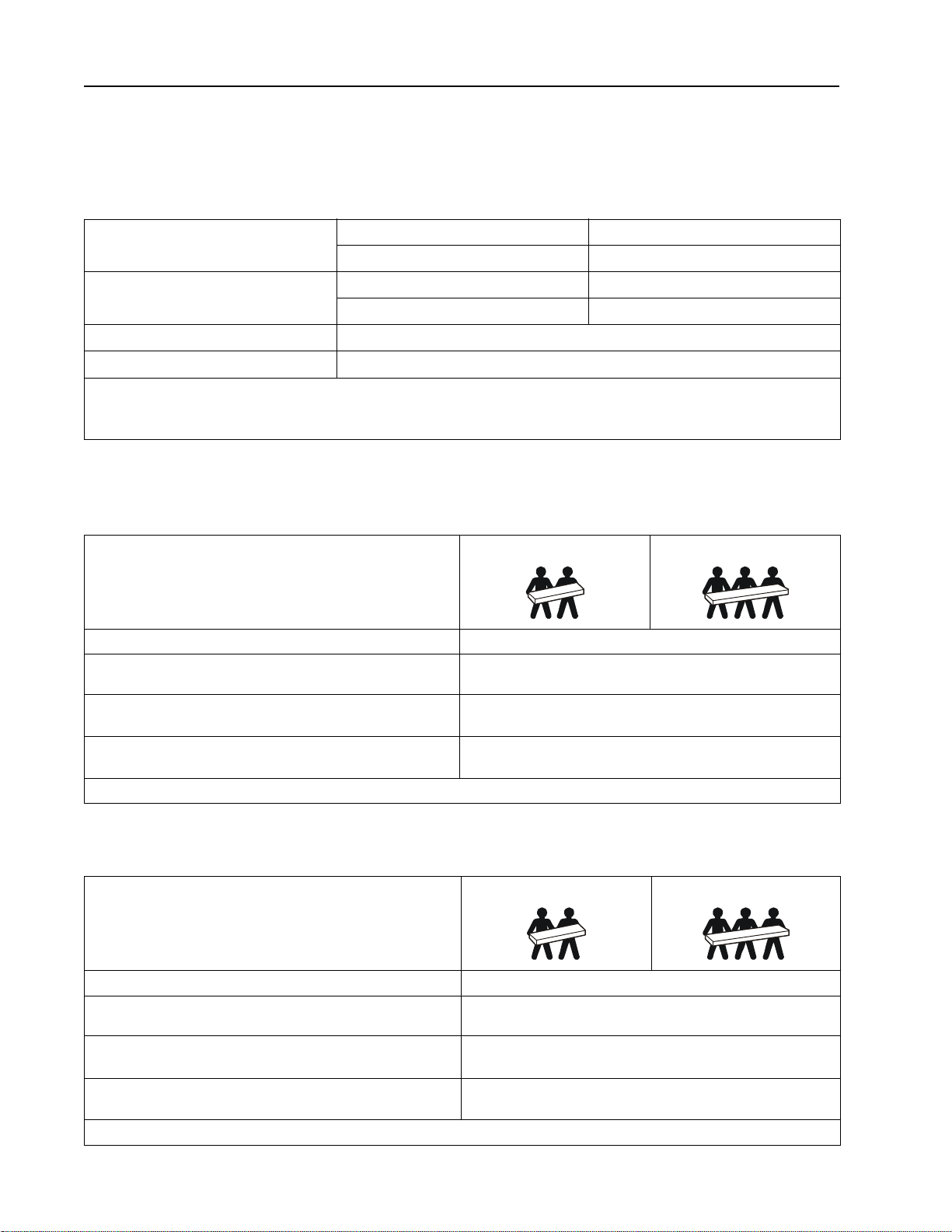
The UPS is heavy. Follow all lif ting guidelin es.
Lifting guidelines 18 - 32 kg (40 - 70 lb) 32 - 55 kg (70 - 120 lb)
Unit weight batteries included, without packaging 26.5 kg (58.4 lb)
Unit weight batteries included, with packaging Rack-Mount models: 34.6 kg (76.2 lb)
Tower models: 31.6 kg (69.7 lb)
Unit dimensions without packaging
Height x Width x Depth
Unit dimensions with packaging
Height x Width x Depth
The model and serial numbe rs a r e on a small label located on the rear pane l.
85 (2U) mm x 432 mm x 560 mm
3.35 (2U) in x 17 in x 22 in
245 mm x 600 mm x 810 mm
9.7 in x 23.6 in x 31.9 in
SRT3000XLA/SRT3000RMXLA/SRT3000RMXLA-NC model
The UPS is heavy. Follow all lif ting guidelin es.
Lifting guidelines 18 - 32 kg (40 - 70 lb) 32 - 55 kg (70 - 120 lb)
Unit weight batteries included, without packaging 32 kg (70.5 lb)
Unit weight batteries included, with packaging Rack-Mount models : 41 kg (90.4 lb)
Tower models: 38 kg (83.8 lb)
Unit dimensions without packaging
Height x Width x Depth
Unit dimensions with packaging
Height x Width x Depth
The model and serial numbe rs a r e on a small label located on the rear pane l.
Smart-UPS On-Line SRT2200XLA/SRT3000XLA Tow er/ R ack-Mount 2U4
85 (2U) mm x 432 mm x 611 mm
3.35 (2U) in x 17 in x 24 in
245 mm x 600 mm x 870 mm
9.7 in x 23.6 in x 34.3 in
Page 7

Battery
NOTICE
RISK OF EQUIPMENT DAMAGE
• Replace the battery at least every 5 years.
• Replace the battery immediately when the UPS indicates battery replacement is necessary.
Failure to follow these instructions can result in equipment damage
SRT2200 models S RT3000 models
Battery type
Replacem e nt ba tt ery module
This UPS has swappable battery modules.
Refer to the appropriat e replacement battery us er m anual for
installation instructions.
Contact your dealer or go the APC by Schneider Electric web site,
www.apc.com for information on replacement batteries.
Number of battery modules 1 battery module
Voltage for each battery mo dule 72 VDC 96 VDC
Total battery voltage for the UPS 72 VDC 96 VDC
Ah rating 5 Ah per battery module
XLBP ca b l e length 500 mm (19.7 in)
Sealed, maintenance-free, Valve Regulated
Lead-Acid battery
APCRBC141 APCRBC152
5Smart-UPS On-Line SRT2200XLA/SRT3000XLA Tow er/Rack-Mount 2U
Page 8
Electrical
Models Max. Rating
Onlin e Gree n Mode
Branch Circuit
Overcurrent Rating /
Building C ircuit Breaker
(CB) C u rrent Rating
SRT2200XLA 2200 VA / 1800 W 1800 VA 20 A
SRT2200RMXLA/SRT2200RMXLA-NC
SRT3000XLA 3000 VA / 2700 W 2700 VA 30 A
SRT3000RMXLA/SRT3000RMXLA-NC
CAUTION
RISK OF FIRE, RISK OF DAMAGE TO EQUIPMENT OR PERSONNEL
Connect the UPS models onl y to a circuit provided with recommended maxi mu m branch circuit overcu rrent protection in
accordance with the National Electrical Code, ANSI/NFPA 70 and the Canadian Electrical Code, Part I, C22.1.
Failure to fol low these instructions can result in fire, equipment damage and minor or moderate injury.
Output
Output Frequency 50 Hz / 60 Hz (Selectable)
Nominal Output Voltage 120 V
Input
Input Frequency 40 Hz - 70 Hz
Nominal Input Voltage 120 V
Nominal Input Current SRT2200 models: 16 A
SRT3000 models: 24 A
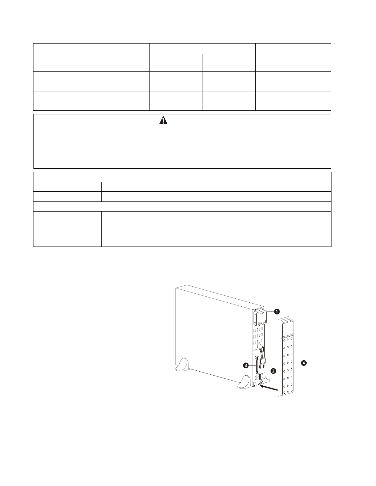
Front Panel Features
Display interface panel
UPS battery connectors
Battery module
Bezel
suo0860a
Smart-UPS On-Line SRT2200XLA/SRT3000XLA Tow er/ R ack-Mount 2U6
Page 9
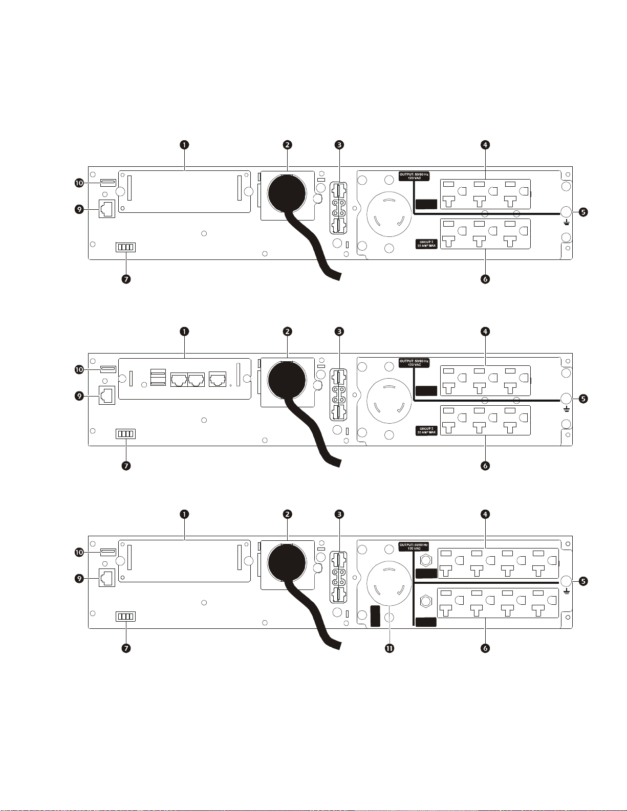
Rear Panel Features
Note: Refer to the table “Key to identify rear panel fe atures” on page 8, that provides a key to the callout numbers for
the rear panel graphics depicted in this manual.
SRT2200XLA/SRT2200RMXLA
P
U
1
O
R
G
P
A
M
M
X
2
A
0
SRT2200RMXLA-NC
suo1092b
SRT3000XLA/SRT3000RMXLA
1
P
U
O
R
G
P
A
M
M
X
2
A
0
suo1093b
P
U
1
G
R
O
P
1
G
R
O
U
P
M
A
M
X
2
0
A
M
P
M
A
X
A
2
0
X
A
3
M
P
P
U
O
M
R
A
G
0
3
R
O
U
P
2
G
A
X
2
0
A
P
M
M
suo1094b
7Smart-UPS On-Line SRT2200XLA/SRT3000XLA Tow er/Rack-Mount 2U
Page 10
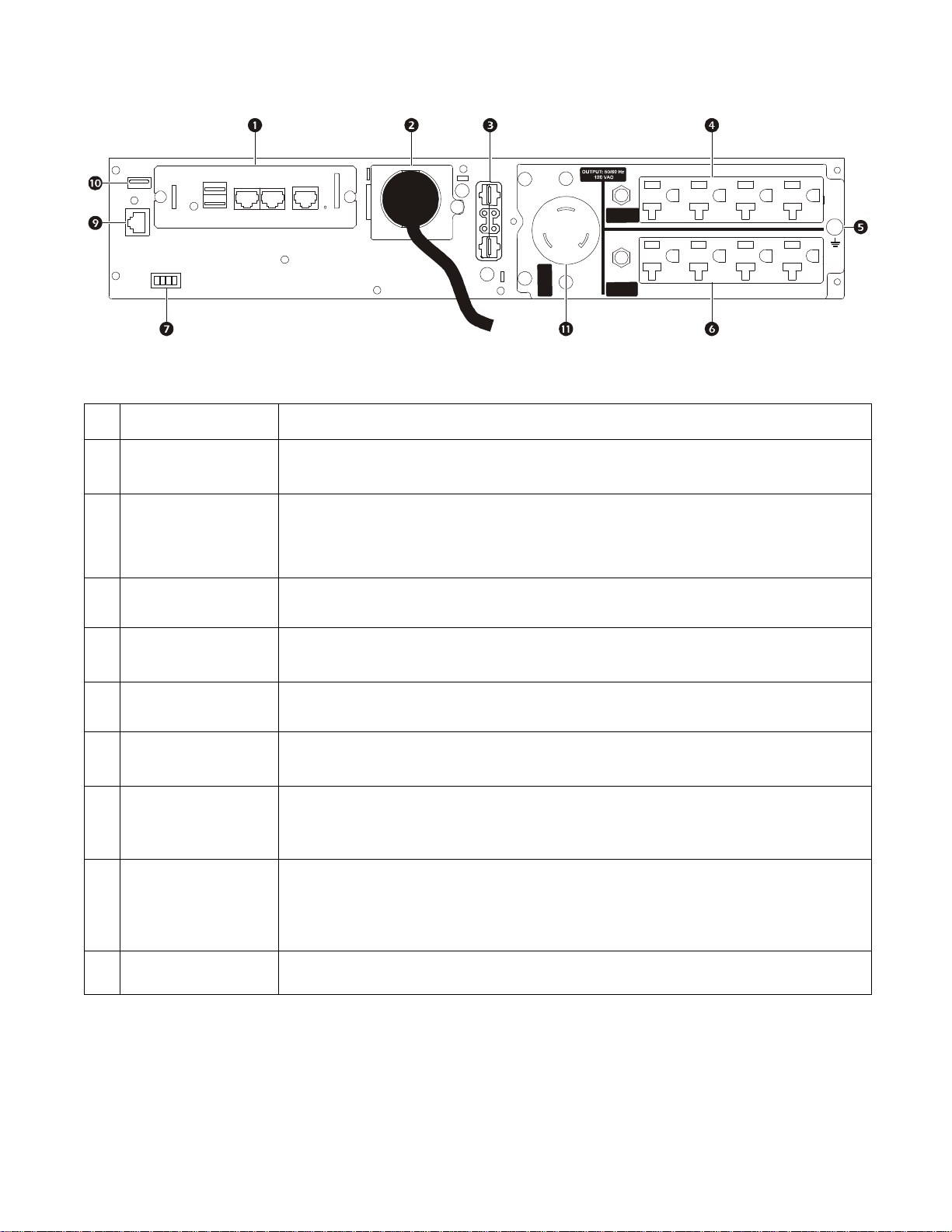
SRT3000RMXLA-NC
Key to identify rear panel features
SmartSlot
AC input power cable
or hardwire input box
External battery
power and
communication
connector
The SmartSlot can be used to connect optional management accessories .
All models have factory installed inpu t power cables.
Hardwired input box is an optional accessory.
Use the external battery cable on the XLBP to connect the UPS and XLBP.
XLBPs provide extende d runtime during power out ages. The UPS will automatically
recognize up to 10 external battery pack s.
U
P
1
G
R
O
P
1
R
O
G
U
M
P
A
M
X
2
0
A
M
P
M
A
X
A
2
0
X
A
3
M
P
U
P
O
M
R
A
G
0
3
R
O
U
P
2
G
A
X
2
0
A
P
M
M
suo1095b
Controllable
outlet group 1
Chassis ground screw
Controllable
outlet group 2
EPO terminal
Serial Com
USB port
Main outlet
Connect electronic devices to thes e outlets.
The UPS and XLBPs have groun d screws fo r connec ting the groun d leads. Prior t o connec ting
a ground lead, disconnect the UPS from mains power.
Connect electronic devices to thes e outlets.
The Emergency Power Off (EPO) terminal allows the user to connect the UPS to a central
EPO system.
The Serial Com port is used to communicate with the UPS.
Use only interface kits suppl ied or approved by APC by Schneider Electr ic. Any other
serial interfa ce cable will be incompatible with the U PS connect o r.
The USB port is used to connect either a server for native operating system communications,
or for software to communicate with the UPS.
Note: Serial a nd USB c ommunic ation s hould not be u sed si multa neously. Use either t he Seri al
Com or the USB port.
Connect electronic devices to the main outlet.
Smart-UPS On-Line SRT2200XLA/SRT3000XLA Tow er/ R ack-Mount 2U8
Page 11

Operation
Connect Equipment
CAUTION
DAMAGE TO EQUIPMENT OR PERSONNEL
• Disconnect the mains input circuit bre aker before installing or servicing the UPS or connected equipment.
• Disconnect internal and external batt eries before installing or servici ng the UPS or connected equipment.
• The UPS contains internal and external batteries that may present a shock hazard even when disconnected from the
mains.
• UPS AC hardwired and pl uggable outlets may be energized by remote or automatic control at any time.
• Disconnect equipment from the UPS before servicing any equipment.
Failure to follow these instructions can result in equi pm ent damage and minor or moderate injury.
Note: The UPS batteries will charge to 90% capacity in the first three hours of normal operation. Do not expect full
battery runtime capability during this initial charge period.
1. Connec t the internal battery module. See Installation manual for details.
2. Connec t equipment to the outlets on the rear panel of the UPS.
Refer to “Controllable Outlet Groups” on page 18.
3. Connec t the UPS to the building utility power.
Turn the UPS On/Off
The first time the UPS is turned on the Setup Wizard screen will run. Follow the prom pts to configure UPS s ettings.
Refer to “Configuration” on page 13.
To turn on the UPS and all con nec ted equipment, press the
prompts to either turn the UPS on immediately or after a delay, then press OK.
NOTE: When there is no input power and the UPS is off, the cold start feature can be used to turn on the UPS and
connected equipm ent using battery power.
To perform a cold start press the
The display panel will illuminate and the
To turn on the output power press the
OK.
To turn output power of f, press the
after a delay, then press OK.
NOTE: Once the UPS output power has been turned off and the AC input has been removed, the UPS will continue to
use the batter y for internal power for 10 minutes. To remove power c ompletely press the
the prompt to select Internal Power Off, then press OK.
POWER ON/OFF button.
POWER ON/OFF button will illuminate red.
POWER ON/OFF bu tton again. S elect the prompt Turn ON with NO AC and press
POWER ON/OFF button. Follow the prompts to eithe r turn the UPS off immedi atel y or
POWER ON/OFF button on the display panel. Follow the
POWER ON/OFF button. Follow
9Smart-UPS On-Line SRT2200XLA/SRT3000XLA Tow er/Rack-Mount 2U
Page 12

UPS Display Interface
su0870f
Output
120.0
v
LOAD
LOAD
POWER ON/OFF button
Button illumination indica tions:
-No illumination, the UPS and the output
power are off
-White illumina tion, the UPS and the
output power are on
-Red illumination, the UPS is on and the
output power is off
Load icon
Disable/mute audible alarm icon
UPS status information
Operation mode icons
ESCAPE button
OK button
UP/DOWN buttons
Controllable outlet group status icons
On-Line
12
Battery status icons
UPS Display Interface operation
Use the UP/DOWN buttons to scroll through the option s. Press the OK b utton to accept the selected option. Press the ESC
button to return to the previous menu.
.
The icons on the LCD display interface screen may vary dependi ng on the installed firmware versions and spec ific UPS
models.
Load icon: The approximate load c apacity percentage is indicated by the number of load bar
sectio n s il lu minate d. E ac h bar repres e n ts 1 6% of the load cap a c it y.
Mute icon: Indicates the audible alarm is disabled/mute.
UPS Status Information
The status information field provides key information on the status of the UPS.
The Standard menu will allo w t he u ser to select one of the five screens listed below. Use the
through the screens.
The Advanced menu will scroll through the five screens automatically.
• Input Vo ltage
• Output Vo ltage
• Output Frequency
• Load
• Runtime
UP/DOWN buttons to scroll
In the case of a UPS event, status updates will be displa yed defining the event or condition that has occurred.
The display scree n illuminates amber to indicate a Message and red to indicate an Alert depending on the severi ty of the
event or condition.
Smart-UPS On-Line SRT2200XLA/SRT3000XLA Tow er/ R ack-Mount 2U10
Page 13

Operation Mode Icons
UPS Statu s Icon
On-Line mode: The UPS is supplying condit ioned mains power to connected equipment.
Bypass mode: The UPS is in Bypass mode and the connected equipm ent will receive mains
power as long as the inpu t voltage and frequency are within the conf igured limits.
Green mode: When in Green mode mains power is se nt directly to the load.
In the event of a mains power outa ge, there will be an interruption in power to the load of up to
10 ms while the U PS switches to On-Line or Battery mode.
When enabling Green mode consideration should be given to devices that may be sensitive to
power fluctuati ons.
Indicates a UPS alert tha t requires attention.
Battery mode: The UPS is supplying battery power to connected equipm ent.
The UPS has detected an internal fault with the battery . Follow the instructions on the screen.
The UPS has detected a critical fault wi th the battery . The battery is at the end of its life an d has
X
to be replaced.
Controllable Outlet Group Icons
Controllable Outlet Group Power Available: The number next to the icon identifies the
specific out let groups that have available power.
Flashing ic on indicates the outlet group is turning from OFF to ON with delay.
Controllable Outlet Group Power Not Available: The number next to the icon identifies
specific outlet groups that do not have available power.
Flashing icon indicates the outlet group is turning from ON to OFF with delay.
Battery Status Icons
Battery Charge Status: Indicates the bat tery charge status .
Battery Charge In Progress: Indica tes the batte r y is charging.
11Smart-UPS On-Line SRT2200XLA/SRT3000XLA Tower/Rack-Mount 2U
Page 14

LCD display interface angle adjustment
The angle of the LCD display interface can be adjusted for eas e in viewing the displayed messages.
1. Rem ove the front bezel.
2. Locate the button on the bottom of the display interface panel.
3. Press the button and slide the bottom of the LCD display interface screen out. An audible click will be
heard when the screen reaches the maximum angle.
a
6
2
9
0
u
s
Menu overview
The UPS Dis pla y Int erface has St a ndard and Advanced menu screens. The preference for Standard or Advanced
menu selections is made during initial installation and can be changed at any time through the Configuration
menu.
The Standard menus include the most comm only used options.
The Advanced menus provide additio nal options .
Note: Actual menu screens may differ by model and firmware version.
Smart-UPS On-Line SRT2200XLA/SRT3000XLA Tow er/ R ack-Mount 2U12
Page 15

UPS Menu Overview
Main Menu
Status
Control
Configuration
Tes t And Diagnostics
Log
About
Accessory***
Smart Slot – Probe 1 T emp erature
Smart Slot - Probe 1 Humidity
Smart Slot – Probe 2 T emp erature
Smart Slot - Probe 2 Humidity
Config Menu
UPS
Battery
Outlets
Communication
Display
Status Menu***
UPS
Battery
Accessory
Control Menu**
UPS
Bypass Control
Outlet Group 1*
Outlet Group 2*
Clear Alarms
Test and Diagnostics Menu
UPS Self Test
Runtime Test
Alarm Test - Short
Alarm Test - Continuous
Event Log
Battery
RBC Health
RBC Summary – Installed MMYY, Replace MMYY
Internal RBC’s, Battery Packs, External RBC’ s
Charge %, Runtime
T em perature, Voltage
Internal Pack – Temperature
Internal Pack – Health
External Pack – Temperature
External Pack - Health
UPS**
Efficiency
Output Power - Watts, VA,Load %
Output - Voltage, Frequency, Cu rre nt
Energy Usage
Battery - Charge %, Runtime
Input Voltage, Frequency
Self Test
Runtime Test
Alert status - Site Wiring Fault
-
UPS
Outlet Group 1**
Turn On Immediately
Turn On With Delay
Turn Off Immediately
Turn Off With Delay
Reboot Immediately
Reboot With Delay
Shutdown Immediately
Shutdown With Delay
Outlet Group 2**
Turn On Immediately
Turn On With Delay
Turn Off Immediately
Turn Off With Delay
Reboot Immediately
Reboot With Delay
Shutdown Immediately
Shutdown With Delay
Bypass Control**
Go into Bypass
Go out of Bypass
Clear Alarms**
No Alarms Exist
UPS**
Turn On Immediately
Turn On With Delay
Turn Off Immediately
Turn Off With Delay
Reboot Immediately
Reboot With Delay
Shutdown Immediately
Shutdown With Delay
Outlets
Main Outlet
Outlet Group 1
Outlet Group 2
Display
Language
Audible Alarm – D isable, Enable
LCD Backlight – Always On, Auto Dim, Auto Off
LCD Settings- Color, Brightness, Contrast
Menu type - Standard / Advanced
Time***
UPS**
Green Mode - Enable / Disable
Output Setting - Lower Volt, Upper Volt
Output Setting – Acceptable Frequency
Byp ass Settings - Lower Volt, Uppe r Volt
Bypass Settings – Frequency
Battery Settings – Low Runtime Warning
Self Test Schedule
Alert Setting - Site Wiring Fault
PDU model- Standard, SRT012
Default Setting
Energy Meter*
Output Setting – Frequency Slew Rate
Battery
Install Date
Replace Notification
Replace Battery Alarm
Communication
SmartSlot- IP Address M ode, IPv4 Address
Modbus*- Enable / Disable, Address
UPS***
UPS Hardware - Part No.
PDU Hardware
UPS Hardware - Serial No.
UPS Hardware - Manufacture Date
UPS Firmware – Revison
UPS – DSP Firmware
UPS – Comm Firmware
UPS Time
Accessor y***
Smart Slot - Serial No.
Smart Slot - Part No.
Smart S lot - Firmware
Smart Slot - MAC Address
Smart Slot – IPv4 Address
About Menu
UPS
Battery
***
Accessory
Part Number
RBC Summar y - I nstalled MMYY, R ep lace MMYY
Battery – Firmware
Battery – Part No.
Menus are subject to change depending on the installed firmware version
Options displayed will vary
Options dis played will v ary based on conne cted accessories.
* Available on the Advanced Menu Screens
** base d on UPS state.
***
Log
Battery
Page 16

Configuration
Language
Francais
Italiano
Setup Wizard
Menu Type
Advanced
UPS Settings
There are four ways to select UPS configuration options.
1. The first time the UPS is tu r n ed o n th e Setup Wizard screen will open. On each menu screen select the
desired settings. Press OK after each UPS setting is selected.
Note: The UPS will not turn on until all of the se ttings have been configured.
2. Main Menu/Configuration/UPS/Default Setting. This screen al lo w s th e us e r to r eset the UPS to f ac to r y
default settings. Press OK after the UPS setting is selected.
Refer to “Config uration” on page 13 and “UPS Menu Overview” .
3. Configure settings using an externa l interface, such as the Network Man age me nt Web interface.
Startup configuration
Function Description
Select the language required for the display interface .
Language options will vary by model and firmware version.
Options:
• English
•Francais
• Italiano
•Deutsch
• Espanol
• Portugues
• Russian
The Standard menu options are the most commonly used opti ons.
The Advanced menu options will be used by IT professionals who need
detailed con f iguration and reporting information.
Setup Wizard
13Smart-UPS On-Line SRT2200XLA/SRT3000XLA Tower/Rack-Mount 2U
Page 17

General settings
Configure these settings at any time, using the display interface, or the Network Management Web Interface.
Param eters Defa ult Value Options Desc ription
Config
Menu
UPS
Green Mode
Output
Lower
Acceptable
Voltage
Output
Upper
Acceptable
Voltage
Output
Frequency
Output
Frequency
Slew Rate
Bypass
Lower
Acceptable
Voltage
Bypass
Upper
Acceptable
Voltage
Disabled Disable
Enable
106 V 97 V - 106 V
127 V 127 V - 136 V
Auto (50/60 ± 3Hz) Aut o (50/60 ± 3 Hz)
50 ± 0.1 Hz
50 ± 3.0 Hz
60 ± 0.1 Hz
60 ± 3.0 Hz
1 Hz/S ec 0.5 H z/ Sec
1 Hz/S ec
2 Hz/S ec
4 Hz/S ec
89 V 89 V - 106 V
138 V 127 V - 146 V
Disabl e or enable Green mode operat ion
If the UPS input voltage is between the lower
acceptable voltage and the higher acceptable
voltage , th e U P S will operate in Green mode when
enabled.
If the output voltage goes outside the acceptable
range the UPS will switch from Green mode to
On-Line mode or to Battery mode.
Set the ou tput frequency for the UPS.
Select the rate of change for output frequency in
Hertz per second.
If the UPS input voltage is between the lower
acceptable voltage and the higher acceptable
voltage, the UPS can enter Bypass mode wh en
enabled.
Bypass
Setting
Acceptable
Frequency
Low
Runtime
Alert
Self Test
Schedule
Wider Frequenc y
47 - 63 Hz
• Wider Fr equency
47 - 63 Hz
• Use Output
The setting Wider Frequency, enables Bypass
mode operation for an input fr equency range of
47-63 Hz.
Frequency Setting
150 secon d s 0 to 1800 seconds The UPS will emit an audible alarm whe n the
Star tup + every 14
days since last te st
Never
Startup
remaining runtime has reached thi s threshold.
This is t he interval at which th e UPS will execute a
Self Test.
Startup + 7 days
Start up + 14 days
Smart-UPS On-Line SRT2200XLA/SRT3000XLA Tow er/ R ack-Mount 2U14
Page 18

Param eters Defa ult Value Options Desc ription
Config
Menu
UPS
Config
Menu
Battery
Site Wiring
Fault
User Can
Acknowledge
• Disable
• Enable
•User Can
Acknowledge
Allows the user to configure the behavior of
the UPS in response to the site wiring fault
alert whic h is gene rated due to wro ng i nput AC
mains connection with input phase and neutral
reversed.
Disable: The UPS never indicates site wiring
fault to the use r.
Enable: UPS alerts the user about site wiring
fault, when detec ted. The alert cannot be reset
until the site wiring fault is corrected.
User Can Acknowledge: UPS alert s the user
about site wiring fault, when detected. The
alert is active till the user acknowledges it by
pressing OK.
PDU Model Standard SRT012 Select the PDU model installed in the UPS for
proper operation of the PDU.
Default
Setting
Reset Energy
Meter
Install Date
Replacement
Notification
Time
No Yes/No Allows the user to restore the UPS factory default
No Yes/No Th e Ener gy Met er store s i nform ati on on UPS output
Battery Installation
Date
180 days 0-360 days To set th e Near End of Life audi ble alarm, select
Month- Year Enter the installatio n d ate of the RBCs.
settings.
ener gy usage.
The Reset feature al lows the user to reset the
Energy Meter to 0 kWh.
the number of days be fore the estimated ba ttery end
of life.
When this date is reached the UPS will emit a n
audible alarm and a message will app ear on the
display inte rface screen.
Example: Using the default value, the Nea r End of
Life audible alarm will occur 180 days before the
estimated end of life date.
Replacement
Battery
Alarm Time
14 days 0-180 day s The Near End of Life audible alarm can be muted.
Enter the number of days b etween the time a Near
End of Life audible alarm is acknowledged and the
next Near End of Life audible alarm occurs.
15Smart-UPS On-Line SRT2200XLA/SRT3000XLA Tower/Rack-Mount 2U
Page 19

Param eters Defa ult Value Options Desc ription
Config
Menu
Display
Config
Menu
Outlets
Language
Audible
Alarm
LCD
Back Light
LCD Setting
Menu Type
Time
Power On
Delay
Power Off
Delay
English
English
Francais
Italiano
Deutsch
Select the language required for the display
interface.
Language op tions will va ry by model and firmware
version.
Espanol
Portugues
Russian
Enable
• Disable
• Enable
Auto Dim Always On
Optimal Values Color
User Choice Standard
UTC time DD-MMM-YYYY
0 seconds 0-1800 seconds Select the amount of time the controllable outlet
90 seconds 0-32767 seconds Select the amount of time the controllable outlet
Auto Dim
Auto Off
Brightness
Contrast
Advanced
HH:MM:SS am/pm
When audible alarms are disabled, the UPS will
never emit an audibl e alarm.
T o con serve en er gy, the LCD b ack lig ht il lum inati on
dims or turns off wh en no eve nts are active.
Full display interface illumination returns when the
UPS chan ges status as a result of an even t or when
any button on the display interface i s pressed.
Adjust t he brightness and cont rast individually for
each LCD back light color.
The Standard menus include the most commonly
used op tions.
The Advanced menu options inc lude al l par ameter s.
Scroll through the fields to set the time.
groups will wait between receiving the command to
turn on and actual startup.
groups will wait between receiving the command to
shutdown and actual shutdown.
Reboot
Duration
Minimum
Return
Runtime
Loadshed
Time On
Battery
Loadshed
Time On
Battery
Loadshed On
Runtime
Loadshed
Runtime
Loadshed On
Overload
8 seconds 4-300 seconds Select the amount of time the controllable outlet
0 seconds 0-32767 seconds Select the amount of battery runtime that must be
Disable Disable
Enable
5 seconds 5-32767 seconds Select the amount of time the cont rollable outlet
Disable Disable
Enable
0 seconds 0-36 00 seconds When the sel ected runtime threshold is reached the
Disable Disable
Enable
groups will remain off before the UPS will rest art.
available before the controllable outlet groups will
turn on using battery power, after a shutdown.
To conserv e battery power the UPS can di sconnect
power from controllable outlet groups not in use.
To configure the disconnect delay time for this
feature use the Loadshed Time On Battery setting.
groups wi ll be allowed to function on battery power
before shutdown.
To conserv e battery power the UPS can di sconnect
power from controllable outlet groups when the
Loadshed Runtime threshold is reach e d.
UPS will shutdow n the controllable outlet groups.
To conserve energy in the event of an overload
conditio n gre ater tha n 105 % outp ut, t he co ntrol l able
outlet groups will immediately turn off. The
contro llable outlet groups will onl y turn on again
with a manual restart com m and once the overload
condition has been corrected.
Smart-UPS On-Line SRT2200XLA/SRT3000XLA Tow er/ R ack-Mount 2U16
Page 20

Param eters Defa ult Value Options Desc ription
Config
Menu
Network
Manage
(for NC
models
only)
IP Address
Mode
IP Addres s
Manual, DHCP,
BOOTP
Progra m I P, Subnet,
Gateway
Refer to the Network Management Utility CD.
17Smart-UPS On-Line SRT2200XLA/SRT3000XLA Tower/Rack-Mount 2U
Page 21

Controllable Outlet Groups
Controllable Outlet Groups provide battery backup power to connected equipment.
Overview
The controllable outlet groups can be configured using the Advanced menu options .
Refer to “General setti ngs” on page 14.
The controllable outlet groups can be configured to independently turn off, turn on, shutdown, switch to sleep
mode, and reboot connected equipment.
• Turn Off: Disconnect output power to connected equipment either immediately using the Turn Off
Immediately feature or after a configured delay using the Turn Off With Delay feature.
NOTE: Controllable outlet groups can be turned on only using the Turn On feature.
• Turn On: Connect output power to conn ec ted equipment either immediate ly using the Turn On
Immediately feature or after a configured delay using the Turn On With Delay feature.
• Shutdown: Disconnects the power to conne cted equipment either immediately or after a configured del ay.
Equipment recon nec ts after a configured dela y wh en mains power becomes ava ilable and other configured
conditions are met.
Each controllable outlet group can be configured s eparately to allow power sequencing for equipment
connected to any cont rollable outlet group.
• Reboot: Di sconnect th e power to connected equipm en t eit h er immediately or after a configured delay.
Reconnect equipm ent after a configured delay when either mains or battery power becomes available and
other configured conditions are met.
Each controllabl e outlet group can be configured separ ately to allow power sequenc ing for loads con nected
to any controlla ble outlet group.
• Sleep: This mode is a reboot with an extended duration where a outlet(s) remain turned off.
Disconnect the power to connected equipment either immediately or afte r a con f igured delay. Reconnect
equipment after a configured delay when either mains or battery power becomes available and other
configured conditions are met.
Each controllable outlet group can be configured s eparately to allow power sequencing for equipment
connected to any cont rollable outlet group.
To configure Sl eep mode use an external interface, such as the Network Manageme nt Web interface.
• Automaticall y turn off or shutdown whe n certain c ondi tions occur, based on user configurat ions set using
the Config Menu Outle ts me nus . Refer to “Configuration” on page 13
Connect controllable outlet groups
• Connect critical equipment to one controllable outlet group.
• Connect peripheral equipment to the other controllable outlet gr oups .
– To conserve batt ery runtime during a power outa ge, nonessential equipment can be configured to shut
down. Use Loadshed T ime on Battery Enable/Disable and Loadshed Time on Battery Sett in g
defined in the General Settings section. Refer to “General settings” on page 14.
– If equipment has dependent periphe rals that must rest art or shut down in a specifi c sequenc e, such as an
ethernet switc h that must restart before a connected server can be restarted, connect the devi ce s to
different outlet groups. Each controll able outlet group can be configured independently of the other
groups.
• Use the Configuration menus to con f igure how the controllable out let groups will react in the event of a
power outage.
Smart-UPS On-Line SRT2200XLA/SRT3000XLA Tow er/ R ack-Mount 2U18
Page 22

Emergency Power Off
Overview
The Emergency Power Off (EPO) option is a feature that will immediately disconnect all connected equipment
from mains power. The UPS will immediately shut down and will not switch to battery powe r.
Connect each UPS to the EPO switch. If multiple units are to be controlled with an EPO switch, each UPS must be
conn e cted sepa ra tely to the E PO switch .
The UPS must be restarted for power to return to connected equipment. Press the
of the UPS.
ON/OFF button o n the front panel
CAUTION
RISK OF DAMAGE TO EQUIPMENT OR PERSONNEL
• Adhere to all national and local ele ctrical codes.
• Wiring must be performed by a qualified elect rician.
• Always connect the UPS to a grounded outlet.
Failure to follow these ins tructions can result in equipm ent damage and minor or moderate injur y.
Normally open contacts
1. If the EPO switch or relay contacts are normally open, insert the wires from the
switch or contacts at pi ns 1 and 2 of the EPO te rmi nal block. Use 16-28 AWG
wire.
2. Secure the wires by tightening the screws.
If the contacts are closed, the UPS will turn OFF and power will be removed from the load.
Normally closed contacts
1. If the EPO switch or relay c ontacts are normally c los ed, insert the wires fro m t he
switch or contacts at pi ns 2 and 3 of the EPO te rmi nal block. Use 16-28 AWG
wire.
2. Insert a wire jumper between pins 1 and 2. Secure the wires by tightening the
three screws at positions 1, 2, and 3.
If the contacts are opened, the UPS will turn OFF and power will be removed from the load.
Note: Pin 1 is the power source for the EPO circuit, it provides a few milliampere of 24 V power.
If the normally closed (NC) EPO configuration is used, the EPO switch or relay should be rated for “dry” circuit
application s, the rating should be for low volt age and low current applica tions. This normally implies the contac ts
are gold plated.
The EPO interface is a Safety Extra Low Voltage (SELV) circuit. Connect the EPO interface only to other SELV
circuits. The EPO interface monitors circuits that have no determined voltage potential. SELV circuits are
controlled by a switch or relay properly isolated from mains power. To avoid damage to the UPS, do not connect
the EPO interface to any c ircuit other than a SELV circuit.
Use one of the following cabl e types to connect the UPS to the EPO switch.
• CL2: Class 2 cable for general use.
• CL2P: Plenum cable for u se in ducts , plenums, and ot her spaces used for environmental air.
• CL2R: Riser cable for use in a vertical run i n a floor to fl oor shaft.
• CLEX: Limited use cable for use in dwellings and for use in racew ays.
• Installation in Canada: Use only CSA certified, type ELC, (ext ra low voltage control cable).
• Installation in countries other than Canada and the USA: Use standard low voltage cable in ac cordance with national
and local regulations.
19Smart-UPS On-Line SRT2200XLA/SRT3000XLA Tower/Rack-Mount 2U
Page 23

Network Management Interface (For NC models only)
Introduction
The UPS has a network port and console port that can be used to access the Network Management Int erface. Ref er
to the Network Management Card utilit y CD suppl ied with this product.
IP Address Configuration
The default TCP/IP confi guration setting DHCP, assumes that a properly configured DHCP server is available to
provide TCP/IP settings to the Network Management Interface.
If the Network Management Interface obtains an IPv4 address from a DHCP server, use the display interface
menus About/Accessory, to see the address.
To s etup a static IPv4 address us e the display interfac e Config menu. Set the IP address Subnet Mask and Gatewa y
from the Config menu.
See the User’s Guide on the Network Management Card Utility CD for user information about the Network
Management Interface and for setup instructions.
Related Documents
The Network Management Card Utility CD contains the following document ation:
• UPS Network Management Card 2 User’s Guide
• Network Management Card Upgrade Utilit ies
• Security Handbook
• PowerNet Management Information Base (MIB) Refere nce Guide
Smart-UPS On-Line SRT2200XLA/SRT3000XLA Tow er/ R ack-Mount 2U20
Page 24

Smart Battery Management
Definitions
• Battery Module: A string of battery cells arranged to produce a battery assembly with a connector.
• Replaceable Ba ttery Cartridge (RBC): An APC battery cartridge co nsisting of one battery mo dule.
Replacement RBCs can be ordered from the APC by Schneid er El ectric web site, www.apc.com.
• Smart Ex ternal Battery Pack ( XLBP): An enclosure that con tains RBC(s) and batt ery management
electronics.
• User Interface (UI): Any interface by which a user can interact with the system. This may include a UPS
display interface, a network management interface or PowerChute™ Network Shutdown software.
NOTE: Do not use a battery that is not APC approved.
The system will not detect the presen ce of a non APC approved battery and may adversely affect the
operation of the system.
Use of a no n AP C appro v ed ba t t er y wil l vo id t he ma n u fa c t urer w a rr a n ty.
Features
Smart Battery Management provides the following features:
• Monitors and informs the us er of the health of each RBC.
• Monitors and shows on the UPS Display Interface screen, the date for the end of useful life for each RBC.
• The UPS emits an audible alarm and shows a message on the UPS Display Interface screen to indicate the
estimated battery end of life. On the UPS Display Interface screen the user can set the number of days
before the audible alarm is hear d and the message appears on the UPS Display Interface screen.
• Automatically detects the addition or removal of XLBPs and RBCs.
• Monitors the internal temperature of each XLBP and automatically adjusts the battery charging.
Maintenance
• RBC maintenance: The APC RBC uses sealed, maintenance-free, Valve Regulated Lead-Acid batteries
and does not require main tenance.
• Runtim e Test (Calibration): This should be performed anytime the stead y st ate load is changed
significantly, for example a new server is added to or removed from the UPS load.
• Battery health monitoring: The battery ener gy output a nd vol tage a re monitore d to a ssess t he heal th of the
installed batteries when the UPS is operating on battery.
Battery health monitori ng is done during a UPS Self Test, a Runtime Calibration T est, and when the UPS
is operating on battery power.
The UPS can be configured to per f orm periodic, automatic Self T ests.
End of useful life
• Near end of li fe notification: A message will appear on the UPS display interf ace screen when each RBC
is approaching the end of its useful life. For conf iguration details refer to Replac em ent Notifi ca tio n Tim e
and Replacement Battery Alarm Time.
The estimated replacement date for each RBC is available through th e UI.
• Needs replacement notification: The UPS display inter f ace screen shows when RBC replacement is
required. The RBC must be repl ac ed as soon as possible.
When an RBC requires replacement, the UPS display in terface may recommend that additional RBCs be
replaced if th ey will soon reach the end of their use f ul life.
CAUTION: Continued operation after end of useful life notification may cause damage to the batteries.
• Recycling: Re move the RBC from the XLBP. Recycle the RBC. Do not disassemble an RBC.
21Smart-UPS On-Line SRT2200XLA/SRT3000XLA Tower/Rack-Mount 2U
Page 25

Replac e th e RB C in a UP S
An RBC should only be disconnected or removed from the UPS temporarily as part of the battery
replacement procedure.
• Disconnect the connected batter y module in the UPS. Slide the RBC out of the UPS.
• Slide the new RBC into the UPS and connect the battery module to the UPS.
• Secure ly co nnect the battery module. Press the battery connector into the UPS until it is firmly conn ected.
A battery that is not properly conn ec ted will cause errat ic UPS operation, abnor mal alert messages and
connected equipment may not receive battery power during power outages.
• After installing the RBC, the UPS dis play interface may prompt the user to verify the status of the replac ed
battery module. If the battery module is new, respond
YES. If the battery module is not new, respond NO.
Recommended actions after installing new RBC
• Verify that the UPS is connected to input power and the output power is turned on. See “Operation” on
page 9 for instructions.
• Perform a UPS Self Test.
• Verify on the UPS displa y interface that t he installation dates for the replace d RBC is set to the current date.
The installa tion dates can be changed manually on the UPS display interface.
For configuration details refer to Battery Install Date in the “General settings” on page 14 of this manual.
• Allow the system to charge for 24 hours to ensure full runtime capability.
XLBP installation and replacemen t
Refer to the External Battery Pack Installat ion G u ide for installatio n and r eplacement instructions.
Smart-UPS On-Line SRT2200XLA/SRT3000XLA Tow er/ R ack-Mount 2U22
Page 26

Troubleshooting
Use the table below to solve minor installation and operation problems.
Refer to the APC by Schneider Electric web site, www.apc.com for assistance with complex UPS problems.
The UPS features firmware that can be upgraded.
Go to the APC by Schneider Electric web site, www.apc.com/Support, or contact your local Customer Care
Center for more information.
Problem and Possible Cause Solution
UPS is not turning on or there is no output
The UPS is not connected to mains
power .
The UPS display interface screen shows
very low or no mains power.
There is an internal UPS alert or
message.
UPS emits an audible alarm
Normal UPS operation when running on
batter y power.
The UPS emi t s an au di bl e al ar m and ha s
a red or amber back light on the UPS
Display Interface scree n.
UPS does not provide expected backup time
The UPS batteries are weak due to a
recent power outage or they are near the
end of service life.
Be sure the power cable is securel y connected to the mains power suppl y.
Check the mains power suppl y to verify acceptable power quality.
The UPS Display Interface screen will show a message to identify the alert or
message a n d co r rective action.
The UPS is operating on batte ry power.
Refer to the status of the UPS as shown on the UPS Display Interface screen.
Press any key to mute all audi ble alarms .
The UPS has detected a fault.
Refer to the display interface screen for information.
Charge the batteries. Batteries require recharging after extended outages and
wear out faster when put into service often or when operated at elevated
temperatures. If the batteries are near the end of service life, consider
replacing the batteries even if the Replace Battery message is not displayed.
The UPS is experiencing an overload
condition.
The conn ected equipment exceeds the specified maximum load. Ref er to the
APC by Schneider Electric web site, www.apc.com for product
specifications.
The UPS will emit a sustained audible alarm until the overload condition is
corrected.
Disconnect nonessential equipm ent from the UPS to correct the overload
condition.
23Smart-UPS On-Line SRT2200XLA/SRT3000XLA Tower/Rack-Mount 2U
Page 27

Problem and Possible Cause Solution
UPS operates on battery pow er while connected to mains power
The input circuit breaker has tripped. Reduce the load on the UPS. Disconnect nonessential equipm ent and reset
the circuit breaker. Check the circuit breaker rating for the connected
equipment.
There is very hi gh, ver y lo w, or di s t orted
input line voltage.
Navigate to the UPS Display Interface screen that shows input voltage.
Verify that the input voltage is within specified operating limits.
If no input voltage is indicated on the UPS Display Interface screen, contact
Customer Support through the APC by Schneider Elec tric web site,
www.apc.com.
The UPS Display Interface sc reen sh ow s
the message Waiti ng for Minimum
The UPS has been configured to operate for a specified period of runtime.
The setting can be changed through the Config/UP S me nus .
Runtime.
UPS Display Interface Status screen shows Overload and the UPS emits a sustained audible alarm
The UPS is experiencing an overload
condition.
The connected equipment exc eeds the maximum load rating for the UPS.
The UPS will emit a sustained audible alarm until the overload condition is
corrected.
Disconnect nonessential equipment from the UPS to correct the overload
condition.
UPS Display Interface Status screen shows UPS is operating in Bypass mode
The UPS received a command to operate
No action is required.
in Bypass mode
The UPS has au tomatically swit ched to
Bypass mode due to an internal UPS
The UPS Display Interface screen will show a message to identify the alert or
dete ct ed err o r an d co rr ect i ve a ct i on.
alert or message.
UPS Display Interface is red or amber and shows an alert or message
The UPS emits a sustained audible alarm
The UPS has detected a probl em during
normal operation.
The UPS Display Interface sc reen sh ow s
the message Dis c onnected Ba t tery.
Follow the in struct ions on the UPS Display Interface screen.
Press any key to mute all audi ble alarms .
Be sure the battery cables are securely connected.
Perform a UPS Self Test to be sure the UPS detects all connect ed batteries.
To pe rform a UPS Se lf Test use the UPS Display Interface menu option Test
and Diagnostics.
The UPS Display Interface sc reen sh ow s
the message Re pl ac e B at tery.
Replace all of the batteries. Cont act APC by Schneider Elect r ic customer
support.
Smart-UPS On-Line SRT2200XLA/SRT3000XLA Tow er/ R ack-Mount 2U24
Page 28

Problem and Possible Cause Solution
Output Off
Bypass
Site Wiring Fault
Press OK to Clear Alarm
Online Green
The UPS display turns red or am ber, displays an alert message, and emits a sustained audible alarm.
Red illumination indicates a UPS alarm that re quires immediate attention.
Amber illumination indicates a UPS alarm that requires attention.
There is an internal UPS alert or
message.
1/1
Power Sys Error - 00100
Contact Customer Support
12
The UPS is experiencing an overload
condition.
1/1
Output Overload
12
The UPS has detected a Site Wiring
Fault.
1/1
Do not attempt to use the UPS. Turn the UPS off and have it serviced
immediately.
Reduce the load on the UPS. Disconnect nonessential equipment.
Correct the building site wiring fault or ignore this message. See Config
Menu UPS in “General s ettings” on page 14.
The Replace Battery alert is displayed
The battery has a weak charge. Allow the battery to recharge for at lea st four hours. Then, perform a
The replacement battery is not properly
connected.
12
UPS Self Test. If the problem persists after recharging, replace the battery.
Be sure the battery cable is sec urely connected.
25Smart-UPS On-Line SRT2200XLA/SRT3000XLA Tower/Rack-Mount 2U
Page 29

Transport
1. Shut down and disconnect al l connected equipment.
2. Disconnect the unit fr om mains power.
3. Disconnect all inter nal and external ba tteries (if applicable).
4. Follow the shipping instructions outlined in the Service section of thi s manual.
Service
If the unit requires service, do not return it to the dealer. Follow these steps:
1. Review the Troubleshooting section of the manua l to eliminate common pro b lems.
2. If the problem persists, contact APC by Schneider Electric Customer Support through the APC by
Schneider Electric web site, www.apc.com.
a. Note the model number and seri al number and the date of purchase. The model and serial numbers
are located on the rear panel of the unit and are available through the LCD disp lay on select models.
b. Call Customer Support. A technician will attempt to solve the problem over the ph one. If this is not
possible, the technician will issue a Returned Material Authorization Number (RMA#).
c. If the un i t is un d er warranty, the repa irs are fr ee.
d. Service procedures and returns may vary internationally . For country specific instructions
refer to the APC by Schneider El ec tric web site, www.apc.com.
3. Pack the unit properly to avoid damage in transit. Never use foam beads for packaging.
Damage sustained in transit is not covere d under warranty.
Note: Before shipping, always disconnect battery modules in a UPS or external battery pack.
The dis c o nn e ct ed in ternal batter i es m a y r em a i n ins i d e th e UP S o r ex t er n al ba tt er y pa ck .
4. Write the RMA# provided by Customer Support on the outside of the package.
5. Return the unit by insured, prepaid carrier to the address provided by Customer Support.
Smart-UPS On-Line SRT2200XLA/SRT3000XLA Tow er/ R ack-Mount 2U26
Page 30

Limited Factory Warranty
Schneider Electri c IT Corporation (SEIT), warrant s its products to be free from defects in materials and
workmanship for a period of three (3) years e xcl uding the bat teries, which are wa rranted for two (2) years from the
date of purchase. The SEIT obli gation under this warranty is limited to repairi ng or replacing, at its own sole
option, any such defective products. Repair or replacement of a defective product or part thereof does not extend
the original warranty period.
This warranty applies only to the original purchaser who must have prope rly registered the product within 10 days
of purchase. Products may be reg is tered online at warranty.apc.com.
SEIT shall not be liab le under the warranty if its testing and exami nation disclose that the alleged defect in the
product does not exis t or was cau se d by end us er or any third person misuse, negligence, impr oper installa tion,
testing, o perati on or use of the pro duct c ontra ry to S EIT r ecommendat ions o f spec if ications . F urther, SEIT shall not
be liable for defects resulting from: 1) unauthorize d attempts to repair or modify th e product, 2) incorrect or
inadequate electrical vol tage or connection, 3) inappropriate on site operation conditions , 4) Acts of God, 5)
exposure to the elements, or 6) theft. In no event shall S EIT have any liability under this warranty for any product
where the serial number has been altered, defaced, or removed.
EXCEPT AS SET FORTH ABOVE, THERE ARE NO WARRANTIES, EXPRESS OR IMPLIED, BY
OPERATION OF LAW OR OTHER WISE, APPLICABLE TO PRODUCTS SOLD, SERVICED OR
FURNISHED UNDER THIS AGREEMENT OR IN CONNECTION HEREWITH.
SEIT DISCLAIMS ALL IMPLIED WARRANTIES OF MERCHANTABILITY, SATISFACTION AND
FITNESS FOR A PARTICULAR PURPOSE.
SEIT EXPRESS WARRANT IES WILL NOT BE ENLARGED, DIMINISHED, OR AFFECTED BY AND
NO OBLIGATION OR LIABILITY WILL ARISE OUT OF, SEIT RENDERING OF TECHNICAL OR
OTHER ADVICE OR SERVICE IN CONNECTION WITH THE PRODUCTS.
THE FOREGOING WARRANTIES AND REMEDIES ARE EXCLUSIVE AND IN LIEU OF ALL
OTHER WARRANTIES AND REMEDIES. THE WARRANTIES SET FORTH ABOVE CONSTITUTE
SEIT’S SOLE LIABILITY AND PURCHASER EXCLUSIVE REMEDY FOR ANY BREACH OF SUCH
WARRANTIES. SEIT WARRANTIES EXTEND ONLY TO ORIGINAL PURCHASER AND ARE NOT
EXTENDED TO ANY THIRD PARTIES.
IN NO EVENT SHALL SEIT, ITS OFFICERS, DIRECTORS, AFFILIATES OR EMPLOYEES BE
LIABLE FOR ANY FORM OF INDIRECT, SPECIAL, CONSEQUENTIAL OR PUNITIVE DAMAGES,
ARISING OUT OF THE USE, SERVICE OR INSTALLATIO N OF THE PRODUCTS, WHETHER SUCH
DAMAGES ARISE IN CONTRACT OR TORT, IRRESPECTIVE OF FAULT, NEGLIGENCE OR
STRICT LIABILITY OR WHETHER SEIT HAS BEEN ADVISED IN ADV ANCE OF THE POSSIBILITY
OF SUCH DAMAGES. S PECIFICALLY, SEIT IS NOT LI ABLE FOR ANY COSTS, SUCH AS LOST
PROFITS OR REVENUE, WHETHER DIRECT OR INDIRECT, LOSS OF EQUIPMENT, LOSS OF USE
OF EQUIPMENT, LOSS OF SOFTWARE , LOSS OF DATA, COSTS OF SUBSTITUANTS, CLAIMS BY
THIRD PARTIES, OR OTHERWISE.
NOTHING IN THIS LIMITED W ARRANTY SHALL SEEK TO EXCLUDE OR LIMIT SEIT LIABILITY
FOR DEATH OR PERSONAL INJURY RESULTING FROM ITS NEGLIGENCE OR ITS
FRAUDULENT MISREPRESENTATION OF TO THE EXTENT THAT IT CANNOT BE EXCLUDED
OR LIMITED BY APPLICA BLE LAW.
To obtain service under warranty you must obtain a Returned Material Authorization (RMA) number from
customer support. Customers with warranty claims issues may access the SEIT worldwide customer support
network through the APC by Schneider Electric web site: www.apc.com. Select your country from the country
selection drop down menu. Open the Support ta b at the top of the web page to obtain information for customer
support in your region . Products must be returne d with transp ortati on char ges pre paid and must be accompani ed by
a brief descriptio n of the problem encountered and proof of date and place of purchase.
27Smart-UPS On-Line SRT2200XLA/SRT3000XLA Tower/Rack-Mount 2U
Page 31

Smart-UPS On-Line SRT2200XLA/SRT3000XLA Tow er/ R ack-Mount 2U28
Page 32

Page 33

APC by Schneider Electric
Worldwide Customer Support
Customer support for this or any othe r APC by Schneider Electric product is availabl e at no char ge in any of
the following ways:
• Visit the APC by Schneider Electric web site to access documents in the AP C by Schneider Electric
Knowledge Base and to submit customer suppor t reque sts.
– www.apc.com (Corporate Headquarters)
Connect to loc alized APC by Schneider Ele ctric web sites for specific countries, each of which
provides customer support information.
– www.apc.com/support/
Global support searchi ng APC by Schneider Electric Knowledge Base and using e-support.
• Contact the APC by Schneider Electric Customer Support C enter by telephone or e-mail.
– Local, country specific centers: go to www.apc.com/support/contact for contact information.
– For information on how to obtain local customer support, contact the APC by Schneider Electric
representative or other distributor from whom you purchased your APC by Schneider Electric
product.
© 2015 APC by Schneider Electric. APC, the APC logo, and Smart- UP S are owned by Schne ider Electric
Industries S.A.S. or their affiliated companies. All othe r trademarks are property of thei r res pec tive owners.
9/2015EN 990-9739
 Loading...