

Page 1

User Manual
TM
Smart-UPS
Uninterruptible Power Supply
110/120/230 Vac
Tower/Rack-Mount 1U
C
SRC250
SRC450
Page 2

Smart-UPSTM C
Uninterruptible Power Supply
250/450 VA
110/120/230 Vac
Tower/Rack-Mount 1U
English
990-1852D, 10/2014
Page 3
Introduction
The APCTM by Schneider Electric Smart-UPSTM Uninterruptible Power Supply (UPS) is designed to
prevent blackouts, brownouts, sags, and surges from reaching your equipment. The uninterruptible
power supply (UPS) filters small utility line fluctuations and isolates your equipment from large
disturbances by internally disconnecting from the utility line. The UPS provides continuous power
from its internal battery until the utility line returns to safe levels or the batter y is fully discharged.
1: INSTALLATION
Unpack
Attention: Read the safety instruction sheet before installation.
Inspect the UPS upon receipt. Notify the carrier and dealer if there is damage.
The packaging is recyclable; save it for reuse or dispose of it properly.
Check the package contents:
Attention: The UPS comes with batt ery disconnected.
UPS
UPS literature kit containing:
Product documentation, safety and warranty information
Documentation CD
PowerChute
Serial communication cable
Rack-mounting hardware
230 V models: Two jumper cables
TM
Business Edition CD
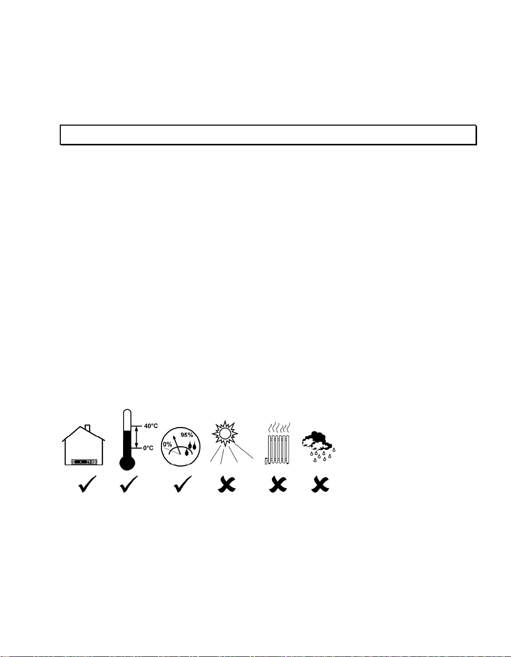
Position the UPS
1
Page 4
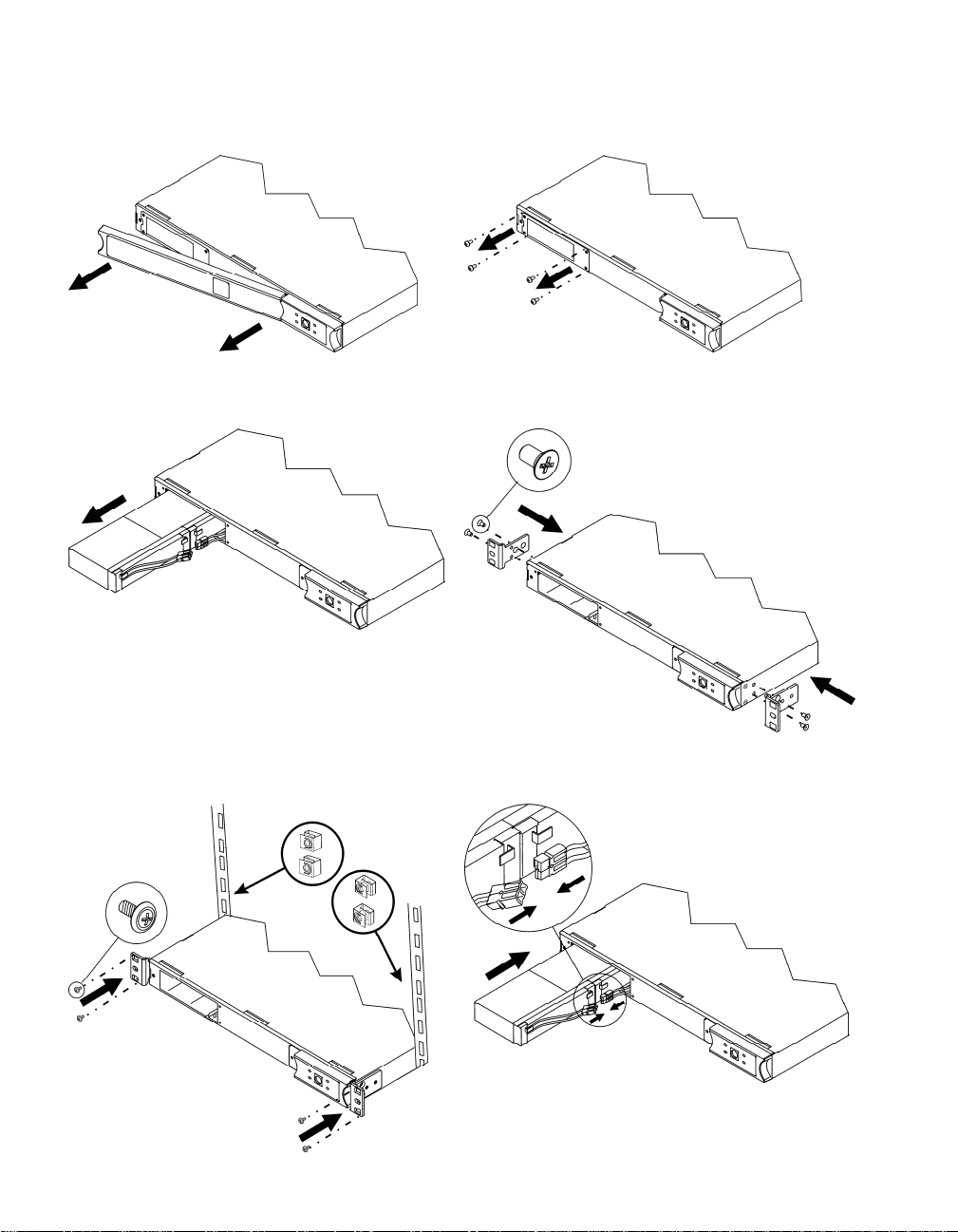
Rack-Mounting
n o
p q Two-post rack-mounting: Utilize the bracket
holes that are offset 6.25”.
r Secure clip nuts to the rack, and attach
brackets with provided screws.
s
2
Page 5
t u
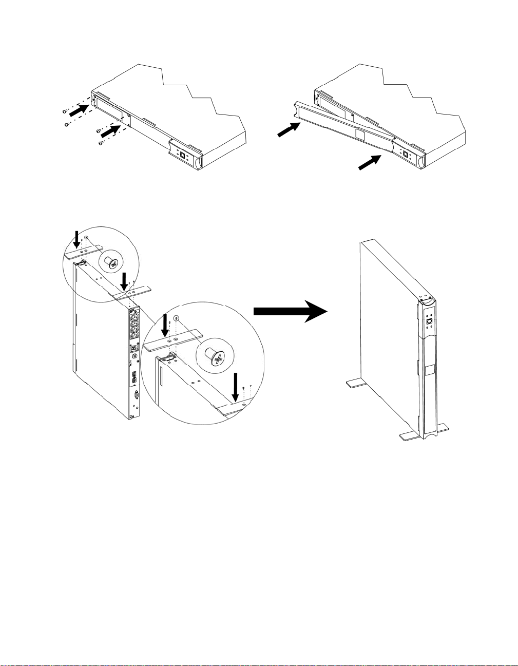
Tower Configuration
Attention: Connect the battery before tower setup by referring to applicable steps in
Rack-Mounting.
3
Page 6
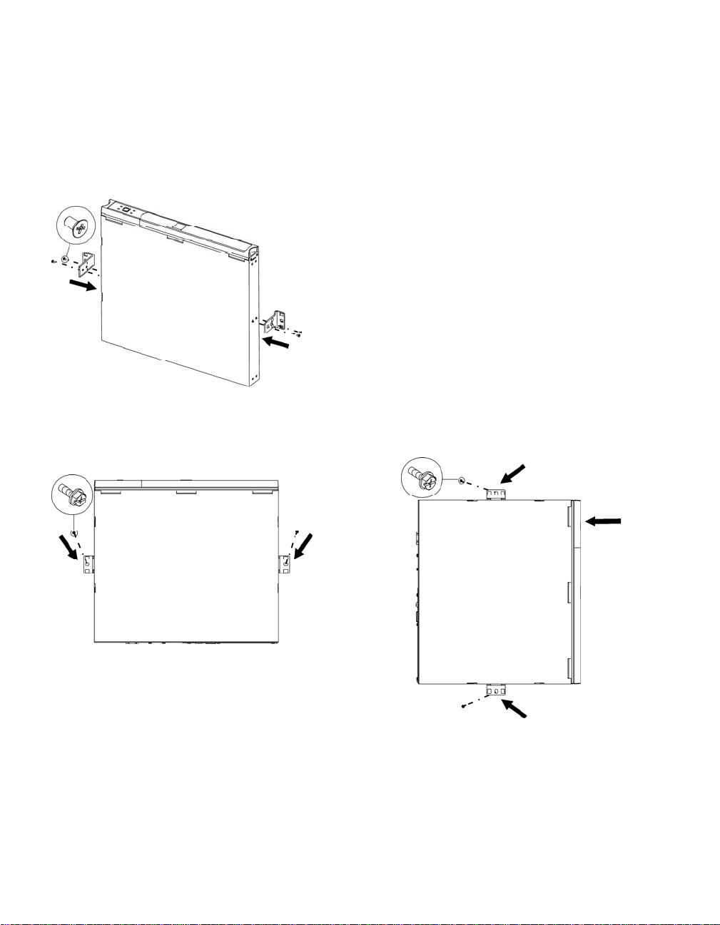
Wall Mounting
Attention: Connect the battery before mounting by referring to applicable steps in
Rack-Mounting.
To avoid a safety hazard, do not mount the unit on the wall with the bezel facing downwards,
or with the display panel at the bottom.
n
o Note: Whenever possible, attach two screws into wall studs. If stud mounting is not possible, use
an expandable wall anchor. Hardware is not included; .25” x 2” lag bolts are recommended. Mount
the UPS in either of the displayed positions.
Display
Panel
4
Page 7

2: START UP
Connect Equipment to the UPS
Rear Panels
110/120 V:
230 V:
Note: A laser printer draws significantly more power than other types of equipment and may overload the UPS.
Connect the UPS to the Network (if Applicable)
Serial Port
Telephone/ Network Surge Suppression Ports
Use only interface kits approved by APC by Schneider Electric.
Use only the supplied cable to connect to the Serial Port. A standard serial interface cable is incompatible
with the UPS.
The UPS features optional telephone/network surge suppression. Connect a single line telephone or a 10
Base-T/ 100 Base-Tx network cable into the RJ-45/RJ-11 telephone/network surge protection IN jack on
the back of the UPS. Use the telephone cable (not supplied) or network cabling (not supplied) to connect
the OUT jack to a fax modem or network port.
Start the UPS
1. Plug the UPS into a two-pole, three-wire, grounded receptacle only. Avoid using extension
cords. 110/120 V models: The power cord is attached to the UPS; the input plug is a
NEMA 5-15P. 230 V models: The power cord set is supplied in the UPS literature kit.
2. 110/120 V models: Check the site wiring fault LED located on the rear panel. It will be
illuminated if the UPS is plugged into an improperly wired utility power outlet
(see Troubleshooting).
3. Turn on all connected equipment. (This allows the UPS to be used as a master on/off switch.)
4. Press the button on the front panel to po wer the UPS.
Note: The battery charges fully during the first four hours of normal oper ation. Do not expect
full battery run capability during this initial charge period. Refer to www.apc.com
runtime charts.
for battery
5. For optimal computer system protection, install PowerChute Busin e ss Edition managemen t
software to fully configure UPS shutdown and alarm settings.
5
Page 8

3: OPERATION
110/120 V 230 V
Front Display Panel
INDICATOR DESCRIPTION
On Line
On Battery
Overload
Replace Battery
The UPS is supplying utility power to the connected equipment.
The UPS is supplying batt ery power to the connected equipment .
The connected loads are dr awing more than the UPS power rating.
The battery must be replaced.
FEATURE FUNCTION
Power Button
Self-Test Automatic: The UPS performs a self-test auto matically when turned on, and
Press this button to turn the UPS on or off. Read on for additional capabilities.
every two weeks thereafter (by default). Du ri ng the self-test, the UPS briefly
operates the connected equipment on battery.
Manual: Press and hold the button for a few seconds to initiate the self-test.
Cold Start
To supply battery power to the UPS and connected equipment in the absence of
utility voltage (see Troubleshooting), press the front display panel button for
one second and release. Th e UPS will beep briefly and go quiet. Press and hold
button again, but for approximately three seconds. Th e unit will emit a
the
sustained beep. Release the button during this beep.
6
Page 9

4: USER CONFIGURABLE ITEMS
NOTE: SETTINGS ARE ADJUSTED THROUGH POWERCHUTE SOFTWARE
FUNCTION
Automatic
Self-Test
FACTORY
DEFAULT
Every 14 days
(336 hours)
USER SELECTABLE
CHOICES
Every 7 days
(168 hours),
Every 14 days
(336 hours),
On Startup Only,
No Self-Test
DESCRIPTION
Set the interval at which the UPS will
execute a self-test.
UPS ID UPS_IDEN Up to eight charac-
ters (alphanumeric)
Date of Last
Manufacture Date mm/dd/yy Reset this date when you replace the
Battery
Replacement
Minimum Capacity
0 percent 0, 15, 50, 90 percent Specify the percentage to which
Before Return from
Shutdown
Voltage Sensitivity
The UPS detects
and reacts to line
High High sensitivity,
Medium sensitivity,
Low sensitivity
voltage distortions
by transferring to
battery operation to
protect connected
equipment.
Alarm Delay After
Line Fail
5 seconds 5 second delay,
30 second delay,
At low battery
condition,
No alarm
Shutdown Delay 60 seconds 60, 180, 300, 600
seconds
Uniquely identify the UPS, (i.e. server
name or location) for network
management purposes.
battery module.
batteries will be charged following a
low battery shutdown before powering
connected equipment.
Note: In situations of poor power
quality, the UPS may frequently
transfer to battery operation. If the
connected equipment can operate
normally under such conditions,
reduce the sensitivity setting to
conserve battery capacity and service
life.
Set the delay to avoid alarms for minor
power glitches.
Set the interval between the time when
the UPS receives a shutdo wn
command and the actual shutdown.
7
Page 10

FUNCTION
Low Battery
Warning
NOTE: SETTINGS ARE ADJUSTED THROUGH POWERCHUTE SOFTWARE
FACTORY
DEFAULT
2 minutes
PowerChute
Business Edition
software provides
automatic,
unattended
USER SELECTABLE
CHOICES
2, 5, 7, 10 minu tes
Times are
approximate.
DESCRIPTION
The UPS will beep when 2 minutes of
battery runtime remains.
Change the low battery warning
interval setting to the time that the
operating system or system software
requires to safely shut down.
shut down when
approximately 2
minutes of battery
operated runtime
remains.
Synchronized
0 seconds 0, 60, 180, 300
Turn-on Delay
High Transfer
Point
110/120 V model:
127 Vac
230 V model:
253 Vac
Low Trans fer P o i nt 110/120 V model:
106 Vac
230 V model:
208 Vac
seconds
110/120 V model:
127, 130, 133,
136 Vac
230 V model:
253, 257, 26 1,
265 Vac
110/120 V model:
97, 100, 103,
106 Vac
230 V model:
196, 200, 20 4,
208 Vac
Specify the time the UPS will wait
after the return of utility power before
turn-on to avoid branch circuit
overload.
Set the high transfer point higher to
avoid unnecessary battery usage when
the utility voltage is usually high and
the connected equipment is specified
to operate with input voltages this
high.
Set the low transfer point lower when
the utility voltage is usually low and
the connected equipment is specified
to operate with input voltages this low.
8
Page 11

5: STORAGE AND MAINTENANCE
Storage
Store the UPS covered in a cool, dry location, with the batt ery fully ch arged.
At -15° to +30°C (+5 to +86° F), charge the UPS battery every six months.
At +30° to +45° C (+86 to +113° F), charge the UPS battery every three months.
Battery Replacement
The UPS battery life differs based o n usage and environment. Consider repl acing the battery every three years.
This UPS has an easy to replace, hot swappable battery. Replacement is a safe procedure, isolated from
electrical hazards. You may lea ve the UPS and connected eq uipment on during the replacement procedure. See
your dealer or contact APC
batteries.
Note: Upon battery disconnection, equipment is not protected from powe r outages.
For battery replacement instruction, refer to applicable steps in Rack-Mounting.
by Schneider Electric, (see Contact Information) for information on replacement
Be sure to deliver the spent battery to a recycling facility or ship it to APC
Electric
in the replacement battery packing material.
by Schneider
9
Page 12

6: TROUBLESHOOTING
Use the chart below to solve minor UPS installation and operation problems. Refer to www.apc.com
with complex UPS problems, and for battery runtime charts.
PROBLEM AND/OR POSSIBLE
SOLUTION
CAUSE
UPS WILL NOT TURN ON
UPS not connected to utility
power supply.
Battery not connected properly.
Very low or no utility voltage. Check the utility power supply to the UPS by plugging in a table lamp. If the
Check that the power cord from the UPS to the utility power supply is
securely connected at both ends.
Check that battery connector is engaged.
light is very dim, have the utility voltage checked.
UPS WILL NOT TURN OFF
Internal UPS fault. Do not attempt to use the UPS. Unplug the UPS, unplug the battery
connector, and have i t serviced immediately.
UPS BEEPS OCCASIONALLY
Normal operating UPS beeps
when running on battery.
None. The UPS is protecting the connected equipment from occasional
utility power irregularities.
UPS IS NOT PROVIDING EXPECTED BACKUP TIME
The UPS battery is weak due
to a recent outage or is near
the end of the service life.
ON-LINE AND OVERLOAD LEDS ARE FLASHING ALTERNATELY
The UPS was shut down
through PowerChute .
Charge the battery. Batteries require recharging after extended outages, and
wear faster when frequently put into service or when operated at elevated
temperatures. If the battery is nea r the end of the service life, consider
replacing even if the replace battery LED is not yet illuminated.
None. The UPS will restart when utility power returns.
ALL LEDS ARE FLASHING OR ON-LINE AND ON-BATTERY LEDS ARE FLASHING
Internal UPS fault. The UPS
has shut down.
ALL LEDS ARE OFF AND THE UPS IS PLUGGED INTO A WALL OUTLET
The UPS is shut down or the
battery is discharged from an
Do not attempt to use the UPS. Turn off the UPS, unplug the battery, and
have it serviced immediately.
None. The UPS will return to normal operation when the power is restored
and the battery has a sufficient charge.
extended outage.
10
Page 13

PROBLEM AND/OR POSSIBLE
SOLUTION
CAUSE
THE OVERLOAD LED IS ILLUMINATED AND THE UPS EMITS A SUSTAINED ALARM TONE
The UPS is overloaded. The
connected equipment is
drawing more VA than the
UPS can sustain.
The connected equipment exceeds the specified “maximum load.”
The alarm remains on until the o verload is removed. Disconnect
nonessential equipment from the UPS to eliminate the overload.
The UPS continues to supply power as long as it is on-line and the circuit
breaker does not trip; the UPS will not provide power from batteries in the
event of a utility voltage interruption.
If a continuous overload occurs while the UPS is on battery, the unit turns
off output in order to protect the UPS from possible damage.
THE REPLACE BATTERY LED IS ILLUMINATED
Weak battery. Allow the battery to recharge for 24 hours. Then, perform a self-test. If the
problem persists after recharging, replace the battery.
Failure of a battery self-test. The UPS emits short beeps for one minute and the replace battery LED
illuminates. The UPS repeats the alarm every five hours. Perform the
self-test procedure after the battery has charged for 24 hours to confirm the
replace battery condition. The alarm stops and the LED clears if the battery
passes the self-test.
THE SITE WIRING FAULT LED ON THE REAR PANEL IS ILLUMINATE D (110/120 V MODEL ONLY)
The UPS is plugged into an
improperly wired utility power
outlet.
Wiring faults detected include missing ground, hot neutral polarity reversal,
and overloaded neutral circuit.
Contact a qualified electrician to correct the building wiring.
THE INPUT CIRCUIT BREAKER HAS TRIPPED
The UPS is overloaded. The
plunger on the circuit breaker
Reduce the load on the UPS by unplugging equipment. Press in the plunger
on the circuit breaker.
has popped out.
UPS OPERATES ON BATTERY ALTHOUGH UTILITY VOLTAGE EXISTS
The UPS input circuit breaker
has tripped.
The line voltage is very high,
low or distorted.
ON-LINE LED
There is no illumination. The UPS is running on battery, or it must be turned on.
The LED is blinking. The UPS is running an internal self-test.
To reduce the load on the UPS, unplug equipment and press in the plunger
on the circuit breaker.
Move the UPS to a different outlet on a different circuit, as inexpensive fuel
powered generators may disto r t th e voltage. If acceptable to the connected
equipment, reduce the UPS sensitivity (see User Configurable Items).
11
Page 14

7: TRAN S PORT AND SERVICE
Transport
1. Shut down and disconnect all connected equipment.
2. Disconnect the unit from utility power.
3. Disconnect all internal and external batteries (if applicable).
4. Follow the shipping instructions outlined in the Service section of this manual.
Service
If the unit requires service, do not return it to the dealer. Follow these steps:
1. Review the Troubleshooting section of the manual to eliminate common problems.
2. If the problem persists, contact APC by Schneider Electric Customer Support through
the APC by Schneider Electric web site, www.apc.com.
a. Note the model number and serial number and the date of purchase. The
model and serial numbers are located on the rear panel of the unit and
are available through the LCD display on select models.
b. Call Customer Support and a technician will attempt to solve the
problem over the phone. If this is not possible, the technician will issue a
Returned Material Authorization Number (RMA#).
c. If the unit is under warranty, the repairs are free.
d. Service procedures and returns may vary internationally. Refer to the
APC by Schneider Electric web site, www.apc.com for country specific
instructions.
3. Pack the unit properly to avoid damage in transit. Never use foam beads for
packaging. Damage sustained in tran sit is not cover ed under warranty.
a. Note: When shipping within the United States, or to the United
States always DISCONNECT ONE UPS BATTERY before shipping
in compliance with U.S. Department of Transportation (DOT) and
IATA regulations. The internal batteries may remain in the UPS.
b. Batteries may remain connected in the XBP during shipment. Not all
units utilize XLBPs.
4. Write the RMA# provided by Customer Support on the outside of the package.
5. Return the unit by insured, prepaid carrier to the address provided by Customer
Support.
12
Page 15

8: LIMITED FACTORY WARRANTY
Schneider Electric IT Corporation (SEIT), warrants its products to be free from defects in materials and workmanship for a
period of two (2) years from the date of purchase. Th e SEIT obligation under this warranty is limited to repairing or replacing,
at its own sole option, any such defective products. Repair or replacement of a defective product or parts thereof does not
extend the original warranty period.
This warranty applies only to the original purchaser who mu st have properly registered the product within 10 days of
purchase. Products may be registered online at warranty.apc.com.
SEIT shall not be liable under the warranty if its testing and examination disclose that the alleged defect in the p roduct does
not exist or was caused by end user or any third person misuse, negligence, improper installation, testing, operation or use of
the product contrary to SEIT recommendations or specifications. Further, SEIT shall not be liable for defects resulting from:
1) unauthorized attempts to repair or modify the product, 2) in correct or inadequate electrical voltage or connection, 3)
inappropriate on site operation conditions, 4) Acts of God, 5) exposure to the elements, or 6) theft. In no event shall SEIT have
any liability under this warranty for any product where the serial number has been altered, defaced, or removed.
EXCEPT AS SET FORTH ABOVE, THERE ARE NO WARRANTIES, EXPRESS OR IMPLIED, BY OPERATION
OF LAW OR OTHERWISE, APPLICABLE TO PRODUCTS SOLD, SERVICED OR FURNISHED UNDER THIS
AGREEMENT OR IN CONNECTION HEREWITH.
SEIT DISCLAIMS ALL IMPLIED WARRANTIES OF MERCHANTABILITY, SATISFACTION AND FITNESS
FOR A PARTICULAR PURPOSE.
SEIT EXPRESS WARRANTIES WILL NOT BE ENLARGED, DIMINISHED, OR AFFECTED BY AND NO
OBLIGATION OR LIABILITY WILL ARISE OUT OF, SEIT RENDERING OF TECHNICAL OR OTHER
ADVICE OR SERVICE IN CONNECTION WITH THE PRODUCTS.
THE FOREGOING WARRANTIES AND REMEDIES ARE EXCLUSIVE AND IN LIEU OF ALL OTHER
WARRANTIES AND REMEDIES. THE WARRANTIES SET FORTH ABOVE CONSTITUTE SEIT SOLE
LIABILITY AND PURCHASER EXCLUSIVE REMEDY FOR ANY BREACH OF SUCH WARRANTIES. SEIT
WARRANTIES EXTEND ONLY TO ORIGINAL PURCHASER AND ARE NOT EXTENDED TO ANY THIRD
PARTIES.
IN NO EVENT SHALL SEIT, ITS OFFICERS, DIRECTORS, AFFILIATES OR EMPLOYEES BE LIABLE FOR
ANY FORM OF INDIRECT, SPECIAL, CONSEQUENTIAL OR PUNITIVE DAMAGES, ARISING OUT OF THE
USE, SERVICE OR INSTALLATION OF THE PRODUCTS, WHETHER SUCH DAMAGES ARISE IN
CONTRACT OR TORT, IRRESPECTIVE OF FAULT, NEGLIGENCE OR STRICT LIABILITY OR WHETHER
SEIT HAS BEEN ADVISED IN ADVANCE OF THE POSSIBILITY OF SUCH DAMAGES. SPECIFICALLY, SEIT
IS NOT LIABLE FOR ANY COSTS, SUCH AS LOST PROFITS OR REVENUE, WHETHER DIRECT OR
INDIRECT, LOSS OF EQUIPMENT, LOSS OF USE OF EQUIPMENT, LOSS OF SOFTWARE, LOSS OF DATA,
COSTS OF SUBSTITUANTS, CLAIMS BY THIRD PARTIES, OR OTHERWISE.
NOTHING IN THIS LIMITED WARRANTY SHALL SEEK TO EXCLUDE OR LIMIT SEIT LIABILITY FOR
DEATH OR PERSONAL INJURY RESULTING FROM ITS NEGLIGENCE OR ITS FRAUDULENT
MISREPRESENTATION OF TO THE EXTENT THAT IT CANNOT BE EXCLUDED OR L I MITED BY
APPLICABLE LAW.
To obtain service under warranty you must obtain a Returned Material Authori zation (RMA) number from cu stomer support.
Customers with warranty claims issues may access the SEIT worldwide customer support network through the APC web site:
www.apc.com
page to obtain in form ation for customer support in your region. Products must be returned with transportation charges prepaid
and must be accompanied by a brief description of the problem encountered and proof of date and place of purchase.
. Select your country from the country selection drop down menu. Open the Support tab at the top of the web
13
Page 16

Page 17

APC by Schneider Electric
Worldwide Customer Support
Customer support for this or any other APC by Schneider Electric product is
available at no charge in any of the following ways:
• Visit the APC by Schneider Electric web site, www.apc.com to access
documents in the APC Knowledge Base and to submit customer support
requests.
– www.apc.com (Corporate Headquarters)
Connect to localized APC by Schneider Electric web site for specific
countries, each of which provides customer support information.
– www.apc.c om/support/
Global support searching APC Knowledge Base and using e-support.
• Contact the APC by Schneider Electric Customer Support Center by
telephone or e-mail.
– Local, country specific centers: go to www.apc.com/support/contact for
contact information.
– For information on how to obtain local customer support, contact the
APC by Schneider Electric repr esent ative or other distribut or fro m whom
you purchased your APC by Schneider Electric product.
© 2014 APC by Schneider Electric. Smart-UPS and PowerChute are owned by Schneider Electric
Industries S.A.S. or their affiliated companies. All other trademarks are property of their respective
owners.
EN 990-1852D
08/2014
 Loading...