

Page 1
Operation Man ual
Smart-UPS X
Uninterrup tible Powe r Suppl y
Rack-Mount 2U
SMX750 VA
SMX1000 VA
SMX 1500 VA
120 Vac
230 Vac
Page 2

Page 3
Product Description
The APC™ by Schneider Electric Smart-UPS™ is a high performance uninterruptible power suppl y (UPS). The
UPS provides protection for elec tronic equipment fro m u tility power blackouts, brownouts, sags, and sur ges , small
utility power fluc tuations and large disturbances. The UPS also provides battery backup power for connected
equipment until utility power returns to safe levels or the batteries are fully discharged.
This user manual is available on the enclosed CD and on the APC by Schneider Electric Web site, www.apc.com.
Important Safety Messages
Read the instructions carefully to become familiar with the equipment before trying to install, operate, service or
maintain it. The f ollowing special message s may appear throughout this manua l or on the equipment to warn of
potential hazards or to call attention to information that clarifies or simplifies a procedure .
The addition of this sym bol to a Caut ion produc t safe ty label indi cate s that a hazard exist s tha t
can result in injury and product damage if the instructions are not followed.
The following safety messages may appear throughout this manual to warn of potential
hazards.
CAUTION
CAUTION indicates a potentially ha zardous situation which, if not av oided, can result in equipment damage and minor or
moderate injury.
CAUTION
CAUTION indicates a potentially hazardous situation which, if not avoided, can result in equipment damage.
Safety and General Information
Inspect the package contents upon receipt. Notify the carrier and dealer if there is any
damage.
Read the Safety Guide supplied with this unit before installing the UPS.
• Adhere to all local and national electric al codes.
• This UPS is intended for indoor use only .
• Do not operate this UPS in dire ct sunlight, in contact with fluids, or where there is excessive dust or
humidity.
• Be sure the air vents on the UPS are not blocked. Allow adequate space for proper ventil ation.
• The battery typic ally la sts for two to f ive year s. Environ menta l fact ors impac t batte ry life. Eleva ted ambie nt
temperatures, poor quality utility power, and frequent short duration discharge s will shorten battery life.
• Connect the UPS power cabl e directly to a wall outlet. Do not use surge protector s or extension cords.
1Smart-UPS X 750/1000/1500 VA 120/230 Vac Rack-Mount 2U
Page 4
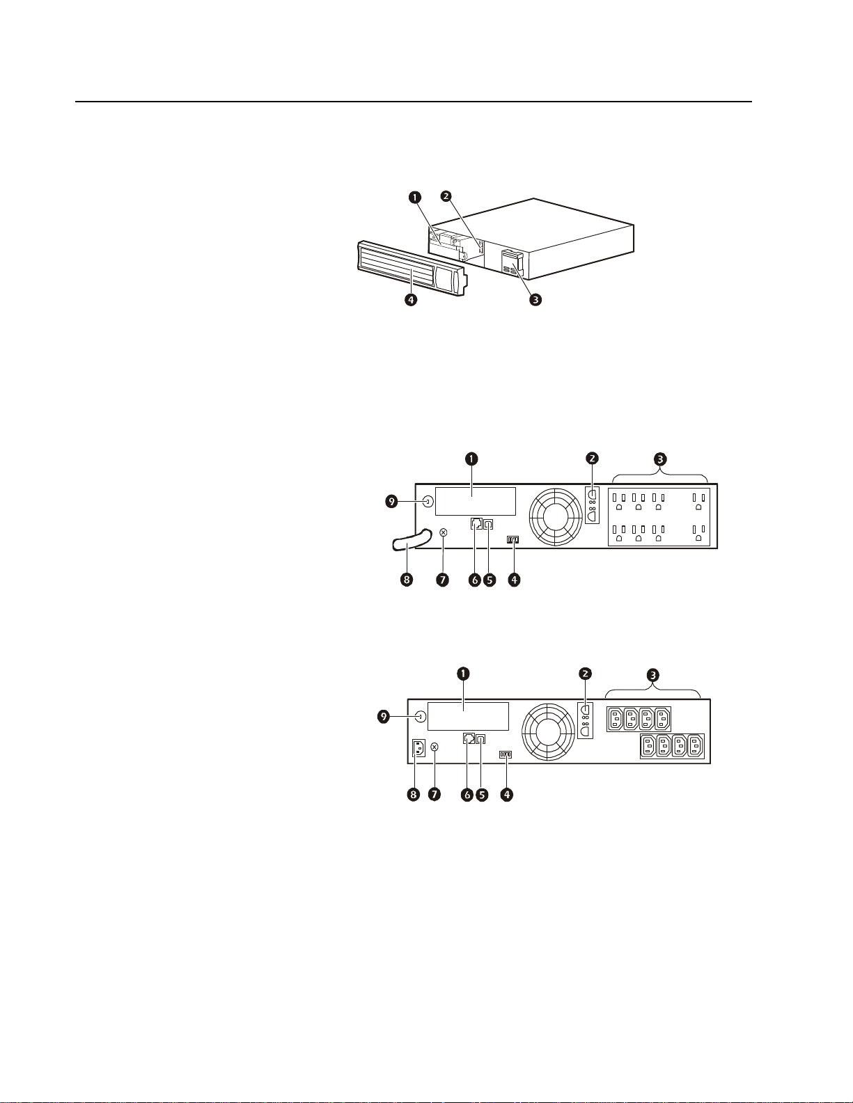
Product Overview
Front Panel Features
Battery
Battery connector
Display interface
Bezel
Rear Panel Features
SmartSlot
External battery pack connector
Outlets
EPO connector
USB port
Serial port
Chassis ground screw
UPS input
Circuit breaker
su0443a
120 Vac
su0340a
230 Vac
su0341a
Smart-UPS X 750/1000/1500 VA 120/230 Vac Rack-Mount 2U2
Page 5

Specifications
Environmental Specifications
For additional specifications, refer to the APC by Schneider Electric Web site at www.apc.com.
Temperature
Maximum
Elevation
Humidity
Operating 0° to 40° C (32° to 104° F)
Storage
Operating 3,000 m (10,000 ft)
Storage 15,000 m (50,000 ft)
0% to 95% relative humidity, non-condensing
Installation
UPS
For UPS installation information, refer to the Smart-UPS X Installation Guide that is included with the
UPS. The guide is also avail able on the enclosed CD and the APC by Schneider E lec tric Web site at
www.apc.com.
Network Management Card
For installation information, refer to the user manual provided with the Network Management Card
(NMC). The user manual is also available on the APC by Schneider Electric Web site at
www.apc.com.
-15° to 45° C (5° to 113° F)
charge UPS battery every six months
External Battery Pack
For installation info rmation, refer to the SMX48RMBP2U external ba ttery p ack Insta llation Gu ide that
is included with th e external batter y pack (XLBP). The guid e is also av ailable on the enclosed CD and
the APC by Schneider Electric Web site at www.apc.com.
3Smart-UPS X 750/1000/1500 VA 120/230 Vac Rack-Mount 2U
Page 6
Operation
Connect Equipment to the UPS
CAUTION
RISK OF EQUIPMENT DAMAGE
• Adhere to all local and national electrical codes.
• Wiring should be performed by qualified electrician.
• Always connect the UPS to a grounde d outlet.
Failure to follow these instructions can result in equipment damage
Note: The UPS will charge to 90% capacity in the first three hours of normal operation. Do not
expect full battery runtime capability during this initial charge period.
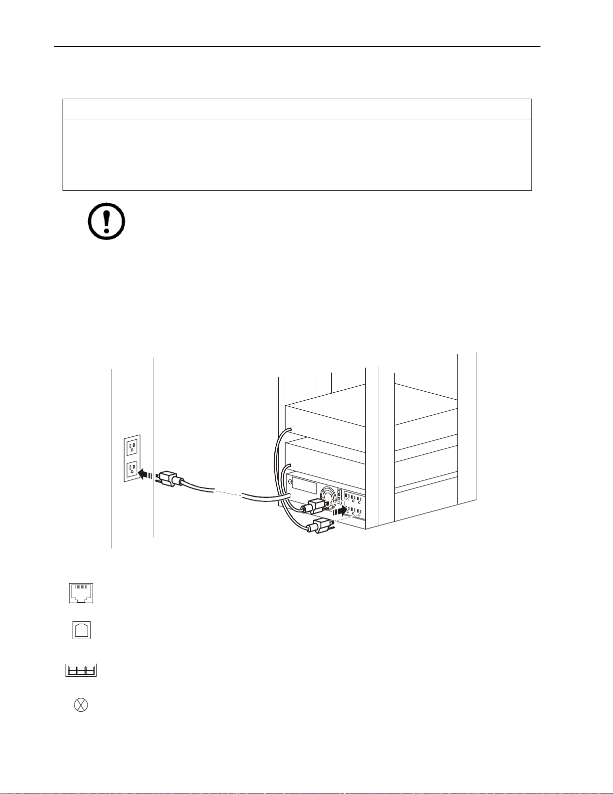
1. Connect equipment to the outlets on the rear panel of the UPS.
2. Connect the UPS to the building utility power.
Always connect the UPS to a two pole, three wire, grounded source.
3. To use the UPS as a master
4. Press the
5. See “Control lable Outlet Groups” o n page 8 for informatio n on how to use the Controllable Outlet Groups.
ON/OFF button on the front panel of the UPS to turn on the UPS and all connected equip me nt.
ON/OFF switch, turn on all the equipment that is connected to the UPS.
Basic Co nn e ctors
Serial port: Connect to a co mpu ter to use power management software.
USB port: Connect to a computer to use power management software.
Note: Serial and USB communication can not be used simultaneously.
Externa l Bat tery Pa ck co nn ec to r: Connect external battery packs to provide extended runtime
during power outages. The UPS can support up to five external battery packs.
Ground Screw: The UPS features a ground screw for connecting the ground lead on surge
suppression devices suc h as a telephone and network line protectors. When connecting a ground
cable, disconnect the UPS from utility power.
su0439a
Smart-UPS X 750/1000/1500 VA 120/230 Vac Rack-Mount 2U4
Page 7
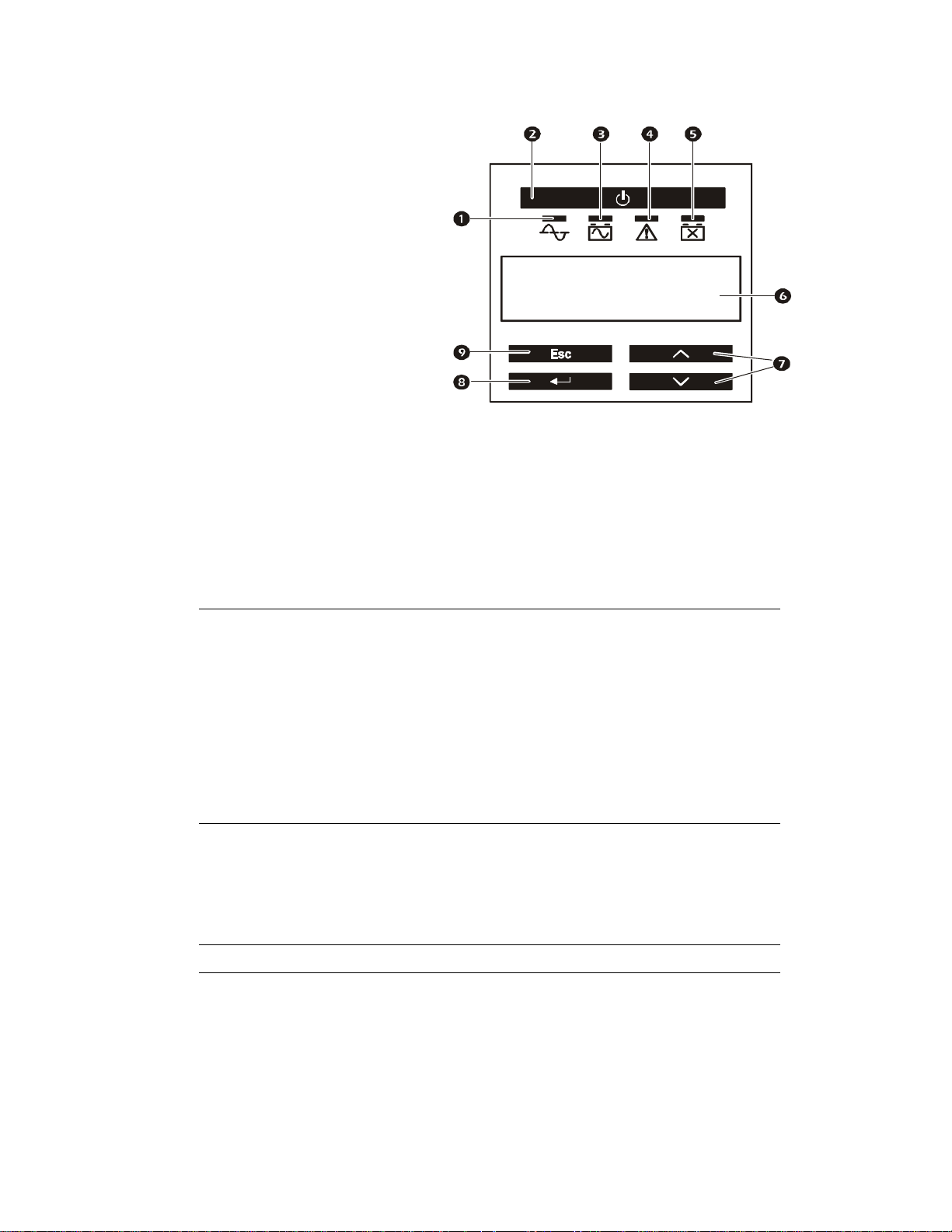
Display Panel
su0343a
A
Electric
Overview
Online LED
UPS Output On/Off button
On Battery LED
Site Wiring Fault LED
Replace Battery LED
Display screen
UP/DOWN arrow buttons
ENTER button
ESCAPE button
Using the display interface
Use the UP/DOWN arrow button s to scrol l th rough the mai n menu op tions . Press ENTER to view the subm enus und er
each main menu option. Press
ESCAPE to exit a submenu and return to a main menu.
PC by Schneider
Standard menus
The Standard menus are the most commonly used menus for the UPS.
Menu General Functions
View basic information about the UPS:
• Operating mode
• Switched Outle t s tatus, On or Off
• Efficiency of the UPS
• Information about the load
Status
Configuration
Test & Diags Use the Test & Diags menu to have the UPS perform a self-test.
• Batter y capacity
• Estim ated runtime
• Input and output voltage and frequency
• Information about the last transfe r to battery power
• Self-test results
• SmartSlot Card information
Configure the settings for the UPS:
• Language
• Local power quali ty: Good, Fair, P oor
• Choose Standa rd or Advanced menus
• UPS Test settings
• Reset to Factory Defaults
About
Display information about this unit:
• Unit model number
• Serial num b er
• Battery information
•Model number
•Installation date
•Suggested batt ery replacement date
•UPS firmware version
5Smart-UPS X 750/1000/1500 VA 120/230 Vac Rack-Mount 2U
Page 8

Advanced menus
The Advanced menus provide additional options for the UPS and are available only if the dis play interface is
configured to use the Adva nced menus.
Menu General Functions
Vi ew detailed information about the UPS:
•Energy meter
Status
Configuration
• Load current
• Status of the SWITCHED OUTLET GROUP(S)
• Battery voltage
•Efficiency
Configure advanced settings for the UPS:
• MAIN AND SWITCHED OUTLET GROUPS—delays and settings
• High and lower tra ns f er points
• Sensitivity settings
• Date of last batte r y replacement
• Output voltage
• Battery settings
• Number of battery packs (not available on all models)
• Reset en e rg y me ter
• UPS te s t se tt in g s
Control
Test & Diags
Log
About
Control the MAIN AND SWITCHED OUTLET GROUPS to turn on, turn off,
shutdown, or reboot.
Perform UPS t es t and diagnostic functions such as user i nterface testing, battery tes ts ,
and battery calibration.
View the event and error logs for information about any changes to the UPS and any
faults.
Vi ew information about the unit:
• Hardware version
•Software version
• NMC information (if appli ca ble)
• SmartSlot Card informati on (if ap plicable)
Smart-UPS X 750/1000/1500 VA 120/230 Vac Rack-Mount 2U6
Page 9

Configuration
UPS Settings
Start up settings
Configure these settings at initial start up, using the display interface or PowerChute™ software.
Note: During start up, use the display interface to configure these settings. If nothing is selected, the
unit will use the default settings.
Function Factory Default Options Description
• English
Language English
Local Power
Quality
Good
• French*
•German*
• Spanish*
•Italian*
•Portuguese*
• Good
•Fair
• Poor
The language for the display interface.
*Language options will vary by model.
Select the quality of input utility power.
• If Good is selected, the unit will go on battery power more often
to provide the cleanest power supply to the connected
equipment.
• If Poor is se lected, the UPS will tolerate more f luctuations in
power and will go on battery power less often.
If unsure of the local power qua lity , select Good.
Menu Type Standard
Standard or
Advanced
The Standard menus display a limited set of menus and options.
The Advanced menus include all parameters.
General Settings
Configure these settings at any time, using the display interface or PowerChute software.
Function Factory Default Options Description
120 V: 140 Vac 120 V: 140-150 Vac To avoid unnecessary battery usage, set the transfer point
High
transfer
point
Low
Transfer
Point
Nominal
Output
Voltage
230 V: 280 Vac 230 V: 280-300 Vac
120 V: 85 Vac 120 V: 75-85 Vac Set the transfer point lower if the utility voltage is
230 V: 170 Vac 230 V: 150-170 Vac
230 V: 230 Vac
120 V: 120 Vac
230 V: 220, 230, 240 Vac
120 Vac: N/A
higher if the utility voltage is chronically high and the
connected equipment is known to work under this
condition. The
change this se tting.
Note: Use the Advanced Me nus to configure this setting.
chron i cally low and the connected equipment can tolerate
this condition.This setting may also be adjusted usi ng the
power quali ty setting.
Note: Use the Advanced Me nus to configure this setting.
Set th e no mina l ou tput vo ltage of the UPS on battery. This
is available on 230 V models only.
POWER QUALITY setting will automatically
7Smart-UPS X 750/1000/1500 VA 120/230 Vac Rack-Mount 2U
Page 10

Function Factory Default Options Description
Select the level of sensitivity to power even ts that the UPS
will tolerate.
• High: The UPS will go on ba ttery power more often to
provide the cleanest power supply to the connected
Transfer
Sensitivity
High High, Low, Medium
equipment.
• Low: The UPS will tolerate more fluctuations in power
and will go on battery power le ss often.
If the connected loa d is sensitive to power disturbances, set
the sensitivity to High.
Low
Battery
Warning
Date of
Last
Battery
Replaceme
nt
Audible
Alarm
Battery
Self-Test
Interval
Setting
Reset to
Factory
Default
150 sec Set the value in seconds
Date set at f actory Reset this date when the ba ttery module is replaced.
On On/Off
On start up and every
14 days since the last
test
No Yes/No Restore the UPS factory default settings.
•Never
• Start up only
• Frequency of test (days)
The UPS wi ll emit an aud ib le alarm wh en the remain ing
runtime has reached this level.
The UPS will mute all audible alarms if this is set to Off or
when the display buttons are pressed.
The interval at which the UPS will execute a self-test.
Controllable Outlet Groups
Overview
The rear panel of the UPS has multiple outlets, some are grouped i nto Controllable Outlet Groups, all of the other
outlets are the UPS outlets, which function as an out let group. All of these groups can independently turn off, turn
on, shut down, and reboot con nec ted equipment.
The Controllable Outlet Groups can be commanded to do the following:
• Turn off: Disconnect from power immediate ly and restart only with a manual command
• Turn on: Connect to power immediately
• Shutdown: Disconn ect powe r in sequ ence, and automa tica lly rea pply po wer in seque nce when ut ility power
becomes available
• Reboot: Shut down and res tart
In addition, the Con trollable Outlet Groups an d the UPS outlets can be configured to do the following:
• Turn on or off in a spec ified sequence
• Automatically turn off or shut down when various co nditions occur
Note: If the Controllable Outlet Groups are not configu r ed, all of the outlets on the unit will still
provide battery backup power.
Smart-UPS X 750/1000/1500 VA 120/230 Vac Rack-Mount 2U8
Page 11

Model specific controllable outlet groups
su04
s
su0
su
su04
su0
Controllable Outl et Group(s) UPS outlets
750 VA 120 Vac
36a
1000 VA 120/230 Vac
435a
1500 VA 120/230 Vac
u0438a
0437a
88a
487a
9Smart-UPS X 750/1000/1500 VA 120/230 Vac Rack-Mount 2U
Page 12

Using the controllable outlet groups and UPS outlets
The UPS outlets function a s a master swi tch. They turn on first when power is applie d, shut off last
when there is a power outage and batte ry runtime has been exhausted.
The UPS outlets must be turned on for the Controllable Outlet Groups to turn on.
1. Connect critic al equipment to the UPS outlets (The 1500 VA units do not have UPS out lets. Connect all
critical equipment to the same outlet group.)
2. Connect peripher al equipment to the Controllable Outlet Groups.
– Nonessential equipment that should shut off quickly in the event of a power outage to conserve battery
runtime can be added to a short power off delay
– If equipment has dependent peripherals that must restart or shut down in a specific order, such as an
ethernet switch that must restart before a connect ed s erve r, connect the devices to separate groups
– Equipment that needs to reboot independently from other equipment should be added to a separate
group
3. Use the Configurat ion m enus to configure how the Controll able Outlet Groups will react in th e eve nt of a
power outage.
Smart-UPS X 750/1000/1500 VA 120/230 Vac Rack-Mount 2U10
Page 13

Customize the controllable outlet groups and the UPS outlets
Use the Control menus to change the controllable outlet groups and the UPS outlet settings.
Function Factory Default Options Description
Name String Outlet
Group
Outlet Group 1
UPS Name String UPS Outlets
Turn On Delay 0 sec
Turn Off Delay 0 sec
Reboot Duration 4 sec
Minimum
Return Time
Load Shed
On Battery
0 sec
Disabled
Edit these names using an external interface, such as the Network
Management Card Web interface.
Set the value in
seconds
Set the value in
seconds
Set the value in
seconds
Set the value in
seconds
• Shutdown wit h
Delay
• Shutdown
The amount of time the UPS or Controllable Outlet
Group will wait between receiving the command to
turn on and the actual startup.
The amount of time that the UPS or Controllable
Outlet Group will wai t between receiving the
command to turn off and the actual shut down.
The amount of time that the UPS or Controllable
Outlet Group must remai n off before it will restart.
The amount o f ba tt ery runt ime tha t must be avai lable
before the UPS or Controllable Outlet Group will
turn on.
When th e u ni t swi tc h es to ba tt ery powe r, the UPS
can disconnect power to the Controllable Outlet
Groups to save runtime.
immediately
• Turn off
immediately
Configure this delay time, use the
WHEN ON BATTERY setting.
LOAD SHED TIME
• Turn off w ith delay
• Disabled
Load Shed Time when
On Battery
Load Shed On
Runtime
Load Shed On
Runtime Remaining
Load Shed on
Overload
Disabled
Disabled
Disabled
Disabled
Set the value in
seconds
• Shutdown wit h
delay
• Shutdown
immediately
• Turn off
immediately
• Turn off w ith delay
• Disabled
Set the value in
seconds
• Disabled
• Enabled
The amount of time the outlets will function on
battery power before they will turn off.
When the battery runtime falls below the specified
value, the Controllable Outlet Group will turn off.
Configure this time using the
REMAINING setting.
LOAD SHED RUNTIME
When the remaining runtime reaches this level, the
Controllable Outlet Group will turn off.
In the eve n t of an ov e rl o ad (gr eater than 10 0 %
output), the Controllable Outlet Group will
immediately turn off to conserve power for critical
loads. The Controllable Outlet Group will only turn
on again wi th a m a nu a l co mmand.
11Smart-UPS X 750/1000/1500 VA 120/230 Vac Rack-Mount 2U
Page 14

Network Management Card Settings
These settings are available only on units tha t have a Network Manag ement Card (NMC) and ar e set in the factory.
These settings can onl y be mo dified using an external interface, like the NMC web interface.
• NMC IP Address Mode
• NMC IP Address
• NMC Subnet Mask
• NMC Default Gateway
Smart-UPS X 750/1000/1500 VA 120/230 Vac Rack-Mount 2U12
Page 15

Emergency Power Off
Overview
The Emergency Power Off (EPO) option is a safety feature that will immediately disconnect all connected
equipment from utility power. The UPS will immediately shut down and will not switch to battery power.
Connect each UPS to the EPO switch, even if the UPS units are used in p arallel.
The UPS must be restar ted for power to return to c onnected equipment. Press the
of the UPS.
Adhere t o all lo ca l and nat i o na l el ec t ri ca l cod e s. All wiring must be perfo rmed by a qua l if i ed electrici an.
ON/OFF button on the front panel
Normally open contacts
1. If the EPO switch or rel ay conta cts are normal ly open, insert t he wi res from th e
switch or contacts at pi ns 1 and 2 of the EPO te rmi nal block. Use 16-28 AWG
wire.
2. Secure the wires by tightening the screws.
If the contacts are closed, the UPS will turn OFF and power will be removed from the load.
Normally closed contacts
1. If the EPO switch or relay contacts are normally closed, insert the wire s from
the switch or contacts at pins 2 and 3 of the EPO terminal block. Use 16-28
A WG wire.
2. Insert a wire jumper between pins 1 and 2. Secure the wires by tightening the
three screws at positions 1, 2, and 3.
If the contacts are opened, the UPS will turn OFF and power will be removed from the load.
Note: Pin 1 is the power source for the EPO circuit, it provides a few milliampere of 24 V power.
If the normally closed (NC) EPO configuration is used, the EPO switch or relay shoul d be ra ted for “dry” circuit
application s, the rating should be for low voltag e and low curre nt applications. This normally implies the conta cts
are gold-plated.
gen0887a
gen0888a
The EPO interface is a Safety Extra Low Voltage (SELV) circuit. Connect the EPO interface only to other SELV
circuits. The EPO interface monitors circuits that have no determined voltage potential. SELV circuits are
controlled by a switch or relay properly isolated from utility power. To avoid damage to the UPS, do not connect
the EPO interface to any circuit other than a SELV circuit.
Use one of the following cabl e types to connect the UPS to the EPO switch.
• CL2: Class 2 cable for gen eral use.
• CL2P: Plenum cable for use in duc ts, plenums, and other spaces us ed for environmental air.
• CL2R: Riser cable for use in a ver tical run in a floor-to-floor shaft.
• CLEX: Limited use cable for us e in dwellings and for use in raceways.
• Installation in Canada: Use only CSA certified , type EL C, (extra-low voltage control cable).
• Installatio n in c ountrie s oth er t han Canada and the USA: Use sta ndar d low-volt age ca ble in accord ance wi th
national and local regulations.
13Smart-UPS X 750/1000/1500 VA 120/230 Vac Rack-Mount 2U
Page 16

Troubleshooting
Problem and Possible Cause Solution
The UPS will not turn on or there is no output
The unit has not been turned on. Press the ON button once to turn on the UPS.
The UPS is not connected to utility
power.
The input circuit breaker has tripped.
The unit shows very lo w or no inpu t
utility voltage.
The battery connector plug is not
securely connected.
There is an internal UPS fault.
Be sure that th e power cable is sec urely co nnecte d to the un it and to the uti lity
power supply.
Reduce the load to the UPS, disconnect noness ential equipment and reset the
circuit breaker.
Check the utility power supply to the UPS by plugging in a table lamp. If the
light is very dim, check the utility voltage.
Be sure that all ba ttery connections are se cure.
Do not attempt to use the UPS. Unplug the UPS and have it serviced
immediately.
The UPS is operating on battery, while connected to utility power
The input circuit breaker has tripped.
There is very high, very low, or
distorted in put line voltage.
Reduce the load to the UPS, disconnect noness ential equipment and reset the
circuit breaker.
Move the UPS t o a dif f eren t ou tle t o n a dif fer ent circ uit . Test the input volt age
with the utility voltage display. If acceptable to the connected equipment,
reduce the UPS sensitivity.
UPS is emits int ermittent beeps
The UPS is in normal operation. None. The UPS is protecting the connected equipment.
UPS does not provi d e ex pec ted backup tim e
Charge the battery . Batteries require recharging after extended outages and
The UPS battery is weak due to a
recent outage or is near the en d
of its service life.
The UPS is overloaded. Check the UP S load display. Unplug unnecessary equipment, such as printers.
wear out faster when put into service often or when operated at el eva ted
temperatures. If the battery is near the end of it s service life, consider
replacing the battery even if the replace ba ttery indicator is not yet
illuminated.
Display interface LEDs flash seque ntially
The UPS has been shut down remotely
through software or an optional ac cessory
card.
None. The UPS will restart automatically when utility power is restored.
The Site Wiring Fault LED illuminates
The UPS displays a fault message and emits a constant beeping sound
Internal UPS fault.
Do not at tempt to use the UPS . Turn the UP S off an d h a v e it s er v iced
immediately.
Smart-UPS X 750/1000/1500 VA 120/230 Vac Rack-Mount 2U14
Page 17

Problem and Possible Cause Solution
All LEDs are illuminated and the UPS is plugged into a wall outlet
The UPS has shut down and the
battery has discharged from an
extended outage.
None. The UPS will return to normal operation when the power is restored
and the batte r y has a su fficient charge.
The Replace Battery LED is illuminated
The battery has a weak charge .
The replacement battery is not
properly connected.
Allow the battery to rechar ge for at least four hou rs. Then, perform a self-t est .
If the problem persi sts after recharging, replace the battery.
Be sure that the battery connec to r is securely connecte d .
The UPS displays a site wiring fault message
Wiring faults detected include
missing ground, hot-neutral,
polarity reversal, and overloaded
neutral circuit.
If the UPS indica tes a sit e wiri ng fau lt, have a qua lif ied ele ctric ia n inspe ct t he
building wiring. (Applicable for 120 V units only.)
15Smart-UPS X 750/1000/1500 VA 120/230 Vac Rack-Mount 2U
Page 18

Service
If the unit re q ui re s service , do no t ret ur n it to th e de al er. Follow t he se st eps:
1. Review the Troubleshooting section of the ma n u al to eliminate common prob lems.
2. If the problem persists, contact APC by Schneider Electr ic Cus tomer Support through the APC by
Schneider Electric Web site, www.apc.com.
a. Note the model number and serial number and the date of purchase. The model and seri al
numbers are located on the rear panel of the unit and are availabl e through the LCD display
on select models.
b. Cal l APC by Schneider Electric Customer Support and a technician will atte mpt to solve
the problem over the phone. If this is not possible, the technician will issue a Returned
Material Authoriza tion Number (RMA#).
c. If the unit is under warranty, the repairs are free.
d. Servic e procedures and returns may vary internation ally. Refer to the APC by Schneider
Electric Web site for country specific instructions.
3. Pack the unit in the origi nal packaging whenever possible to avoid damage in transi t. Never use foam
beads for packaging. Damage sustained in transit is not covered under warranty.
a. Always DISCONNECT THE UPS BATTERIES before shipping. The United States
Department of Transportation (DOT), and the International Air Transport
Association (IATA) regulations require that UPS batteries be disconnected before
shipping. The internal batteries may remain in the UPS.
b. External Battery Pack products are deenergized when disconnected from the associated UPS
product. It is not necessary to disconnect the internal batteries for shipping. Not all units utilize an
external battery pack.
4. Write th e RMA# provided by Customer Support on the outside of the package.
5. Return the unit by insured, prepaid carrier to the address provided by Customer Support.
Transport the unit
1. Shut down and disconnect all connected equipment .
2. Disconnect the unit fr om uti lity power.
3. Disconn ect all internal and extern al batteries (if applicable).
4. Follow the shipping instructions outlined in the Service section of this manual.
Smart-UPS X 750/1000/1500 VA 120/230 Vac Rack-Mount 2U16
Page 19

Two Year Limited Factory Warranty
This warranty applies only t o the products you purchase for your use in accordance with this manual.
T erms of warranty
Schneider Electric IT (SEIT) warrants it s products to be free from defects in materials and workmanship for a period of two
years from the date of purchase. SEIT will r epair or replace defect ive products covered by this warranty. This warranty does not
apply to eq uipment th at has b een damag ed by acci dent , ne glige nce or mi sapp lic ation or ha s be en alt er ed or m odifi ed in any w ay.
Repair or replacement of a de fective product or part thereof does not extend the original warranty period. Any parts furnished
under thi s w arranty may be new or factory remanufactured. For country specific warranty information, refer to th e AP C by
Schneider Electric Web site at www.apc.com.
Non-transferable warranty
This warranty extends only to t he original purchaser who must have properly registered the product. The produ ct may be
registered at the APC by Schneider Electric Web site, www.apc.com.
Exclusions
SEIT shall not be liable under the warranty if its testing and examination disclose tha t the alleged defect in th e product does not
exist or was caused by end user’s or any third person’s misuse, negligence, improper installation or testing. Further, SEIT shall
not be liable under the warranty for unauthor ized attempts to repair or modif y wr ong or inadequate electrical voltage or
connection, inappropriate on si te operation conditions, corros ive atmosphe re, repair, inst allation, e xposure to the elements, Acts
of God, fire, theft, or installation contrary to SEIT recommendations or specifications or in any event if the SEIT serial number
has been altered, defaced, or removed, or any other cause beyond the range of the intended use.
THERE ARE NO WARRANTIES, EXPRESS OR IMPLIED, BY OPERATION OF LAW OR OTHERWISE, OF
PRODUCTS SOLD, SERVICED OR FURNISHED UNDER THIS AGREEMENT OR IN CONNECTION
HEREWITH. SEIT DISCLAIMS ALL IMPLIED W ARRANTIES OF MERCHANTABILITY, SA TISFACTION AND
FITNESS FOR A PARTICULAR PURPOSE. SEIT EXPRESS WARRANTIES WILL NOT BE ENLARGED,
DIMINISHED, OR AFFECTED BY AND NO OBLIGATION OR LIABILITY WILL ARISE OUT OF, SEIT
RENDERING OF TECHNICAL OR OTHER ADVICE OR SERVICE IN CONNECTION WITH THE PRODUCTS.
THE FOREGOING W ARRANTIES AND REMEDIES ARE EXCLUSIVE AND IN LIEU OF ALL OTHER
WARRANTIES AND REMEDIES. THE WARRANTIES SET FORTH ABOVE CONSTITUTE SEIT’S SOLE
LIABILITY AND PURCHASER’S EXCLUSIVE REMEDY FOR ANY BREACH OF SUCH WARRANTIES. SEIT
WARRANTIES EXTEND ONLY TO PURCHASER AND ARE NOT EXTENDED TO ANY THIRD PARTIES.
IN NO EVENT SHALL SEIT, ITS OFFICERS, DIRECT ORS, AFFI LIATES OR EMPLOYEES BE LIABLE FOR
ANY FORM OF INDIRECT, SPECIAL, CONSEQUENTIAL OR PUNITIVE DAMAGES, ARISING OUT OF THE
USE, SERVICE OR INSTALLATI ON, OF THE PRODUCTS, WHETHER SUCH DAMAGES ARISE IN CONTRACT
OR TORT, IRRESPECTIVE OF FAULT, NEGLIG ENCE OR STRICT LIABILITY OR WHETHER SEIT HAS BEEN
ADVISED IN ADVANCE OF THE POSSIBILITY OF SUCH DAMAGES. SPECIFICALLY, SEIT IS NOT LIABLE
FOR ANY COSTS, SUCH AS LOST PROFITS OR REVENUE, LOSS OF EQUIPMENT, LOSS OF USE OF
EQUIPMENT , LOSS OF SOFTWARE, LOSS OF DATA, COSTS OF SUBSTITUENTS, CLAIMS BY THIRD
P ARTIES, OR OTHERWISE.
NO SALESMAN, EMPLOYEE OR AGENT OF SEIT IS AUTHORIZED TO ADD TO OR VARY THE TERMS OF
THIS WARRANTY. WARRANTY TERMS MAY BE MODIFIED, IF AT ALL, ONLY IN WRITING SIGNED BY AN
SEIT OFFICER AND LEGAL DEPARTMENT.
Warranty claims
Customers w ith warranty claims i ssues may a ccess the SEIT customer support network through the Support page of the APC by
Schneid er Electric Web site, www.apc.com/support. Select your coun try fr om the cou ntry sel ec tion dr op down m enu at the to p
of the Web page. Sel ect the Support tab to obtain contact information for customer support in your region.
17Smart-UPS X 750/1000/1500 VA 120/230 Vac Rack-Mount 2U
Page 20

Page 21

APC by Schneider Electric
Worldwide Customer Support
Customer support for this or any othe r APC by Schneider Electric product is available at no charge in any of
the following ways:
• Visit the APC by Schneider Electric Web site to access documents in the APC by Schneider Electr ic
Knowledge Base and to submit customer suppor t reque sts.
– www.apc.com (Corporate Headquarters)
Connect to localized APC by Schneider Electric Web sites for specific countries, each of which
provides customer support information.
– www.apc.com/support/
Global support searchi ng APC by Schneider Electric Knowledge Base and using e-support.
• Contact the APC by Schneider Electric Customer Support Center by telephone or e-mail.
– Local, country specifi c cent ers: go to www.apc.com/support/contact for contact information.
– For information on how to obtain local customer support, contact the APC by Schneider Electric
representative or other distributors from whom you purchased your APC by Schneider Electric
product.
Select models are ENERGY STAR® qualified.
For more information go to www.apc.com/site/recycle/in dex.cfm/energy-efficiency/energy-star/
© 2013 APC by Schneider Electric. APC, the APC logo, Smart-UPS and PowerChute are owned by Schneider
Electric Industr ies S.A.S. or their affiliated companies. All other tr ademarks are property of their respective
owners.
04/2013990-3458B
 Loading...