

Page 1

g
g
y
y
g
y
y
y
g
g
g
gy
y
y
g
g
g
p
g
prop
Thank You!
Thank you for selecting the American Power Conversion SmartSlot Series
Measure-UPS II. It has been desi
nance-free service. Please read this manual! It provides installation and
operatin
Save this manual! It includes important instructions for the safe installation of
tor
instructions that will help you get the most from your accessory.
our accessory. Further, it includes instructions for obtaining fac-
service.
ned for many years of reliable, mainte-
Radio frequency interference
WARNING:
approved b
authorit
NOTE:
limits for a Class A di
These limits are desi
ful interference when the equipment is operated in a commercial environment. This equipment
ener
manual, ma
tion of this equipment in a residential area is likel
ference in which case the user will be required to correct the interference
at his own expense.
This di
emissions from di
tions of the Canadian Department of Communications.
Le présent appareil numérique n’émet pas de bruits radioélectriques
dépassant les limites applicables aux appareils numériques de la Class A
prescrites dans le Rè
ministère des Communications du Canada.
Chan
es or modifications to this unit not expressly
the party responsible for compliance could void the users
to operate the equipment.
This equipment has been tested and found to compl
ital device pursuant to Part 15 of the FCC Rules.
ned to provide reasonable protection against harm-
enerates, uses, and can radiate radio frequency
and, if not installed and used in accordance with the instruction
cause harmful interference to radio communications. Opera-
to cause harmful inter-
ital apparatus does not exceed the Class A limits for radio noise
ital apparatus set out in the Radio Interference Regula-
lement sur le brouillage radioélectrique édicté par le
with the
Entire contents copyright © 1995 American Power Conversion. All rights
reserved. Re
hibited. PowerChute is a re
Call-UPS, and the stylized APC logo are trademarks of APC. All other trademarks are
roduction in whole or in part without written permission is pro-
istered trademark of APC. SmartSlot, PowerNet,
erty of their respective owners.
Page 2

Contents
g
y
1 Introduction . . . . . . . . . . . . . . . . . . . . . . . . . . . . . . . . . . . . . . . . .1
2 Installation . . . . . . . . . . . . . . . . . . . . . . . . . . . . . . . . . . . . . . . . . .3
3 Operation Check. . . . . . . . . . . . . . . . . . . . . . . . . . . . . . . . . . . . . .5
4 Sensor Zone Connections. . . . . . . . . . . . . . . . . . . . . . . . . . . . . . .6
5 Sensor Selection . . . . . . . . . . . . . . . . . . . . . . . . . . . . . . . . . . . . . .8
6 Maintenance . . . . . . . . . . . . . . . . . . . . . . . . . . . . . . . . . . . . . . . . .9
7 Troubleshootin
8 Service . . . . . . . . . . . . . . . . . . . . . . . . . . . . . . . . . . . . . . . . . . . .11
9 Specifications . . . . . . . . . . . . . . . . . . . . . . . . . . . . . . . . . . . . . . .12
10 Declaration of Conformit
11 Index. . . . . . . . . . . . . . . . . . . . . . . . . . . . . . . . . . . . . . . . . . . . . .14
. . . . . . . . . . . . . . . . . . . . . . . . . . . . . . . . . . . . .10
. . . . . . . . . . . . . . . . . . . . . . . . . . . . .13
Page 3
1. Introduction
g
g
y
y
The SmartSlot Measure-UPS II performs temperature and humidity
sensin
Measure-UPS II supports up to four zones of contact monitorin
of which supports both normall
Measure-UPS II reports temperatures from 0 to 60 °C (32 to 140 °F)
and relative humidit
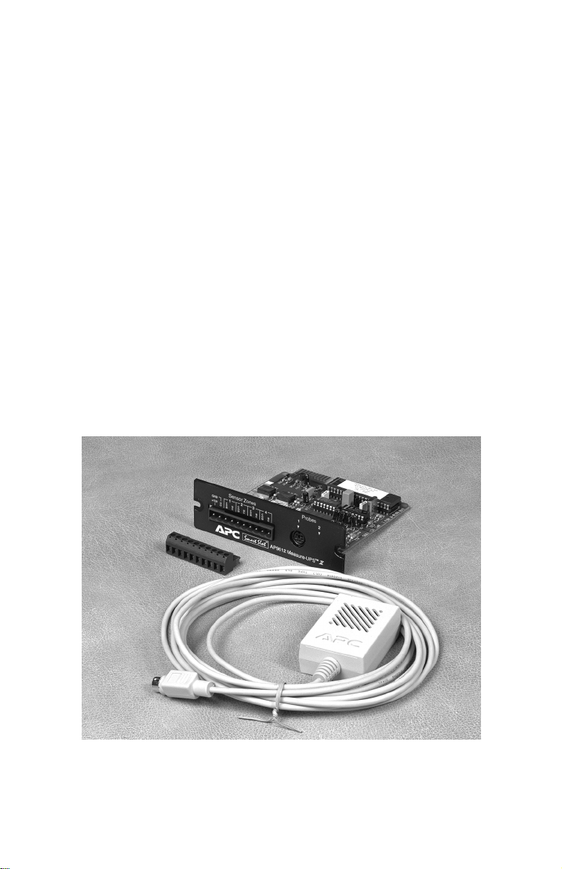
Measure-UPS II model AP9612T includes:
Measure-UPS II model AP9612TH includes:
, as well as contact monitoring.
, each
open and normally closed contacts.
from 10 to 90%.
• Measure-UPS II SmartSlot UPS accessory
• Temperature probe (model AP9512T)
• Screw terminal connector for contact monitoring
• Hook and loop probe fasteners.
• The Measure-UPS II SmartSlot UPS accessory
• Combined temperature and humidity probe (model
AP9512TH)
• Screw terminal connector for contact monitoring
• Hook and loop probe fasteners.
Figure 1, SmartSlot Measure-UPS II
Page 4

Safety Notice
y
y
gly
y
g
y
y
j
g
g
g
The SmartSlot Measure-UPS II UPS accessory is intended solely for
use in supplementar
mend this product for life or propert
in
sell Measure-UPS II for use in such applications. APC disclaims
all liabilit
described herein.
arising out of improper use of Measure-UPS II as
surveillance of equipment. APC does not recom-
protection. APC will not know-
Hardware and Software Compatibility
SmartSlot Measure-UPS II requires an APC device with a SmartSlot
as a host. This can be a UPS equipped with a SmartSlot, or a SmartSlot Expansion Chassis in combination with a UPS that supports the
Expansion Chassis.
Measure-UPS II also requires some means of reportin
can be an
Note
UPS II information when it is installed in con
PowerNet SNMP adapter or PowerNet SNMP a
SNMP Mana
within popular network mana
number on the back cover of this manual for more information.
one or a combination of the following:
• Call-UPS II™ Remote UPS Management Device
®
•PowerChute
software
• PowerNet SNMP adapter
• PowerNet SNMP agent.
: An
SNMP management system can read and use Measure-
er provides a high level graphical user interface for use
Plus UPS power management and diagnostic
unction with an APC
ement systems. Contact APC at the
its data. This
ent. PowerNet
Page 5
2. Installation
Use the following procedure to install SmartSlot Measure-UPS II:
1. Install and configure any software or hardware that will be used
with Measure-UPS II for data reporting (see software and hardware compatibility above).
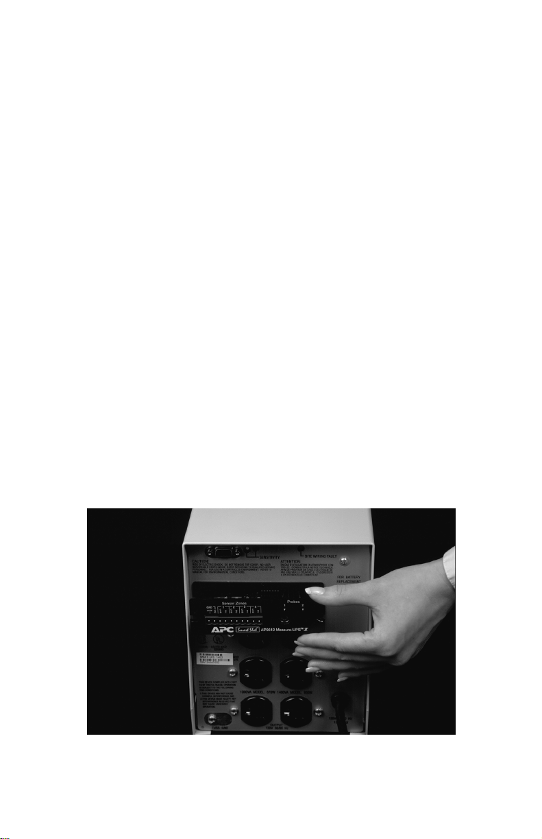
2. Using figure 2 as a guide, install Measure-UPS II in the host
SmartSlot. Use a #2 Phillips head screwdriver to remove the host
device SmartSlot cover plate. Install Measure-UPS II. Replace the
cover plate screws. Note: Measure-UPS II is sensitive to static
electricity. Handle Measure-UPS II by the end plate only. Do not
touch the exposed printed circuit board. While it is not possible to
install Measure-UPS II upside down, it is possible to damage it in
the attempt. Note that the edges of the printed circuit board align
with the locating slots in the sides of the SmartSlot. The SmartSlot may be oriented horizontally or vertically in the host device.
The host device may be on or off during installation.
3. Connect the supplied probe to probe connector 1 on MeasureUPS II.
4. Place the probe where desired using the supplied hook and loop
fasteners, if needed. Note: The Measure-UPS II probe is designed
for use in a controlled environment. Place it in an area that is
within the environment limits set in the specifications (see section
9.) The location must be free from direct sunlight, excessive
moisture, and dust.
Note
: probe connector 2 is not used in Measure-UPS II.
Figure 2, SmartSlot installation
Page 6
Do not:
g
• Cover any of the ventilation holes on the probe
• Immerse the probe or place it where dew can be expected to
form
• Use the probe in an environment with chlorine gas or insecticides.
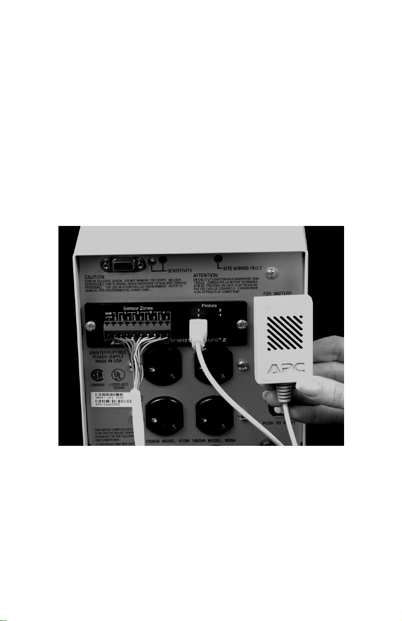
5. The contact monitoring connection is a two piece design. Connect
contact closure-type sensors to the removable screw terminal
block using the information in section 4 as a guide. The connector
accepts wire sizes from 14 AWG (1.6 mm2) to 26 AWG (.4
mm2). Strip the wire insulation 0.25" (6 mm). Connect the screw
terminal block to the Sensor Zones connector of Measure-UPS II.
See fi
ure 3 below for a completed installation.
Figure 3, completed installation
Page 7

3. Operation Check
1. Confirm the basic operation of Measure-UPS II. Use the data
reporting system (see hardware and software compatibility in section 1) to confirm that Measure-UPS II is working. W ith the probe
(temperature or temperature and humidity) connected to probe
connector 1, Measure-UPS II should transmit temperature or temperature and humidity values to the reporting system. Note:
Reported humidity values will be less than 2% RH when using the
temperature only probe. If the probe is not properly connected
both temperature and humidity readings will be very low.
2. Confirm contact sensing by activating each sensor in turn according to the sensor manufacturers recommendation. Use the data
reporting system to verify that each sensor operates as planned.
Page 8

4. Sensor Zone Connections
y
y
g
y
p
p
y op
y
y
y
y
Sensor Zones Connector Pinout
Pin Function
1
2
3 zone 1 common
4 zone 1 normall
5 zone 2 common
6 zone 2 normall
7 zone 3 common
8 zone 3 normall
9 zone 4 common
10 zone 4 normall
ower supply, +12 Vdc nominal, 60 mA max.
ower supply ground
and normall
en connection for all zones
closed
closed
closed
closed
Connection Information
Measure-UPS II supports normally open and normally closed loop
s
stems, and allows mixing of normally open and normally closed
sensors on an
usin
multiple sensors in one zone and for system hookup.
Note:
Do not cross connect sensors used with Measure-UPS II with
those of an
zone. See the figures below for more information on
other system.
Page 9

In order to avoid receiving alarm indications on unused zones, install a
j
g
y
umper wire between the COM and NC connectors for each unused
zone.
To use more than one sensor on a zone, follow the dia
Connect normall
in series.
open sensors in parallel and normally open sensors
ram below.
Page 10

See below for a typical hookup. Note that in this example system zone
y
y
y
1 is a normall
detector supplied b
Zone 3 is a combination normall
Zone 4 is not used.
closed motion zone with power for the passive infrared
Measure-UPS II. Zone 2 is a normally open zone.
open and normally closed zone.
Page 11

5. Sensor Selection
g
g
y
y
g
y
y
y
y
y
Measure-UPS II may be used with any dry contact closure type sensors. The Measure-UPS II sensor inputs are desi
cuits that have no volta
Measure-UPS II sensor inputs to an
t
pe will void the warranty and may result in damage to Measure-UPS
II.
In
eneral, any normally open (NO) or normally closed (NC) dry con-
tact sensor ma
• Magnetic contact switches
• Window foil
• Tamper switches
• Heat detectors
• Water sensors
• Pressure sensors
Additionall
detectors that need power. These t
• Passive infrared (body heat) detectors
•Smoke sensors
• Photo relay detectors
and 2 of the Sensor Zones connector for sensors that require power.
For more information in what sensors ma
Measure-UPS II, please call the APC PowerFax Interactive Fax S
tem at the number on the back cover of this manual. Request document number 1310. Or call technical support. See the back cover for
more information.
be used with Measure-UPS II. Such sensors include:
, Measure-UPS II provides a source of power for those
Measure-UPS II provides 12 Vdc at up to 60 mA at pins 1
e potential of their own. Connection of
circuit other than a dry closure
pes include:
ned to monitor cir-
or may not be used with
s-
Page 12

6. Maintenance
g
g sy
y
y
y ty
Measure-UPS II requires periodic maintenance. Confirm contact sensin
using the sensor manufacturers recommended intervals and methods. Use the data reportin
as planned.
Clean the temperature (or temperature and humidit
there is a visible buildup of dust. Gentl
Do not blow an
pe of compressed gas into the probe.
stem to verify that each sensor operates
) probe whenever
brush or vacuum off the dust.
Page 13

7. Troubleshooting
Problem Possible Cause Solution
Constant Alarm on
one or more unused
zones.
Constant low tem-
perature and humid-
ity readings.
No communication
with UPS or acces-
sories.
Unused zones not
jumpered.
12 Vdc supply (pin
1) shorted to ground
or overloaded.
Measure-UPS II has
failed.
Connect a wire
between the COM
and NC terminals of
all unused zones (see
section 4).
Correct short
circuit—examine all
sensors that use the
12 Vdc power
supply.
If removing Mea-
sure-UPS II from the
host cures the com-
munication problem
for other accessories,
call technical support at the number
on the back cover of
this manual.
Incorrect sensor
readings.
Always reports very
low temperature
and/or humidity.
Improper sensor
wiring.
Probe not connected
properly.
Correct sensor
wiring—see
section 4.
Connect probe
properly—see
section 2.
Page 14

8. Service
If the SmartSlot Measure-UPS II requires service:
1. Check Measure-UPS II using the troubleshooting chart in section
7 before calling for service.
2. Note the model number of the Measure-UPS II, the serial number,
and the date purchased. See the back cover of this manual for the
correct telephone number and call customer service. A technician
will ask you to describe the problem and help solve it over the
phone, if possible, or will give you an RMA#. If customer service
is not available in your area, call the dealer that sold the SmartSlot
Measure-UPS II. If Measure-UPS II is under warranty , repairs are
free. If not, there will be a charge for repair.
3. It is important to pack the SmartSlot Measure-UPS II properly to
avoid damage in transit. Damage sustained in transit is not covered under warranty.
4. Include a letter with your name, RMA#, address, copy of the sales
receipt, description of the trouble, your daytime phone number,
and a check (if necessary).
5. Mark the RMA# on the outside of the package. The factory cannot accept any package without this marking.
6. Return Measure-UPS II and its probe by insured, prepaid carrier
to the address given by the technician.
Page 15

9. Specifications
g
g
y
y
y
g
g
g
g
g
g
g
g
Electrical
SmartSlot specification compatible
Operatin
Operatin
Temperature accurac
Humidit
Sensor Zone input response time: 100 milliseconds
Power output: 12 Vdc nominal, 60 mA max.
Physical
Size (H x W x D): 4 x 4 x 1.5 inches
Wei
Shippin
voltage: 16 - 27 Vdc
current draw: 30 mAdc (exclusive of an
attached sensors)
: ±2° C (±3.6° F), from 0 to 40° C
(32 to 104° F)
accuracy: ±8% RH, 10 to 90% RH, at 25° C
(77° F);
±8% RH, 30 to 80% RH, from 15
to 30° C (from 59 to 95° F)
round referenced
(10.2 x 10.2 x 3.8 cm)
ht: 0.3 lb. (140 g)
weight: 0.7 lb. (320 g)
Environmental
Operating elevation: 0 to 3,000 m
Stora
e elevation: 0 to 15,000 m
Operatin
Stora
Probe operatin
temperature: 0 to 40 °C (32 to 104° F)
e temperature: 0 to 45 °C (32 to 113° F)
temperature: 0 to 60° C (32 to 140° F)
Approvals
EMC verification: FCC Class A, DOC class A,
EN55022 Class A
Electroma
netic immunity: EN50082-1 verified
Page 16

10. Declaration of Conformity
y
g
g
y
g
g
Application of Council Directives: 89/336/EEC
Standards to Which Conformit
Manufacturers Name: American Power Conversion
Importer’s Name and Address:
T
pe of Equipment: Measure-UPS II
Model Number: AP9612T, AP9612TH
Serial Numbers: A95050000001–A961299999999
Year of Manufacture: 1995, 1996
is Declared: EN55022, EN50082-1
132 Fair
West Kin
rounds Road
ston, RI 02892 USA
I, the undersi
conforms to the above directive(s).
Place: No. Billerica, MA USA Joseph Pomata,
Date: 6/1/95
ned, hereby declare that the equipment specified above
re
ulatory compliance engineer
Page 17

Limited Warranty
American Power Conversion (APC) warrants its products to be free from defects in
materials and workmanship for a period of two years from the date of purchase. Its obligation under this warranty is limited to repairing or replacing, at its own sole option, any
such defective products. To obtain service under warranty you must obtain a Returned
Material Authorization (RMA) number from APC or an APC service center. Products
must be returned to APC or an APC service center with transportation charges prepaid
and must be accompanied by a brief description of the problem encountered and proof
of date and place of purchase. This warranty does not apply to equipment which has
been damaged by accident, negligence, or misapplication or has been altered or modified in any way. This warranty applies only to the original purchaser who must have
properly registered the product within 10 days of purchase.
EXCEPT AS PROVIDED HEREIN, AMERICAN POWER CONVERSION MAKES
NO WARRANTIES, EXPRESS OR IMPLIED, INCLUDING WARRANTIES OF
MERCHANTABILITY AND FITNESS FOR A PARTICULAR PURPOSE. Some
states do not permit limitation or exclusion of implied warranties; therefore, the aforesaid limitation(s) or exclusion(s) may not apply to the purchaser.
EXCEPT AS PROVIDED ABOVE, IN NO EVENT WILL APC BE LIABLE FOR
DIRECT, INDIRECT, SPECIAL, INCIDENTAL, OR CONSEQUENTIAL DAMAGES ARISING OUT OF THE USE OF THIS PRODUCT, EVEN IF ADVISED OF
THE POSSIBILITY OF SUCH DAMAGE. Specifically, APC is not liable for any
costs, such as lost profits or revenue, loss of equipment, loss of use of equipment, loss of
software, loss of data, costs of substitutes, claims by third parties, or otherwise.
Life support policy
Use of this equipment in life support applications where failure of this equipment can
reasonably be expected to cause the failure of the life support equipment or to significantly affect its safety or effectiveness is not recommended.
 Loading...