

Page 1

Installation Guide Smart-UPS™ SCL400RMJ1U 100 Vac, 400 VA
Important Safety Instructions
SAVE THESE INSTRUCTIONS - This manual contains important instructions that should be followed during installation
and maintenance of the Smart-UPS and batteries.
Read these instructions carefully and look at the equipment to become familiar with the device before trying to install,
operate, service or maintain it.
Download the Operation Manual either by scanning the QR code on the equipment or by following instructions given in
“Operation Manual Link” on page 8, before operating the equipment.
Safety and General Information
General safety
• Adhere to all national and local electrical codes.
• All wiring must be performed by a qualified electrician.
• Changes and modifications to this unit not expressly approved by APC by Schneider Electric could void
the warranty.
• This UPS is intended for indoor use only.
• Do not operate this unit in direct sunlight, in contact with fluids, or where there is excessive dust or humidity.
• Be sure the air vents on the UPS are not blocked. Allow adequate space for proper ventilation.
• For a UPS with a factory installed power cord, connect the UPS power cable directly to a wall outlet. Do not use
surge protectors or extension cords.
• Always practice safe lifting techniques adequate for the weight of the equipment.
• Remove the batteries before installing the UPS.
• Always install peripheral equipment above the UPS in rack-mount configuration.
• Additional safety information can be found in the Safety Guide supplied with this unit.
Deenergizing safety
The UPS contains internal batteries and may present a shock hazard even when disconnected from the branch circuit (mains).
Before installing or servicing the equipment verify the following:
• Mains circuit breaker is in the OFF position.
• The UPS is disconnected from mains or wall outlet.
• Battery packs are disconnected.
Page 2

Electrical safety
• The protective earth conductor for the UPS carries the leakage current from the load devices (computer
equipment). An insulated ground conductor is to be installed as part of the branch circuit that supplies input
power to the UPS. The conductor must have the same size and insulation material as the grounded and
ungrounded branch circuit supply conductors. The conductor will typically be green, with or without a
yellow stripe.
• The UPS input ground conductor must be properly bonded to protective earth at the service panel.
• If the UPS input power is supplied by a separately derived system, the ground conductor must be properly
bonded at the supply transformer or motor generator set.
• Use tools with insulated handles.
• Do not handle any metallic connector before power has been disconnected.
• For models with a hardwired input, the connection to the branch circuit (mains) must be performed by a
qualified electrician.
• Leakage current for a pluggable, Type A UPS may exceed 3.5 mA when a separate ground terminal is used.
Battery safety
WARNING
RISK OF CHEMICAL HAZARD AND EXCESSIVE HEAT
• Replace the battery at least every 10 years.
• Replace the battery immediately when the UPS indicates battery replacement is necessary.
• Replace battery at the end of its service life.
• Replace batteries with the same number and type of batteries as originally installed in the equipment.
• Replace the battery immediately when the UPS indicates a battery over-temperature condition or UPS
internal over-temperature. Power off the UPS, unplug it from the AC input, and disconnect the batteries.
Do not operate the UPS until the batteries have been replaced.
Failure to follow these instructions can result in death or serious injury.
• Schneider Electric uses Lithium Ion batteries. Under normal use and handling, there is no contact with the
internal components of the battery.
• The battery typically lasts for five to ten years. Environmental factors impact battery life. Elevated ambient
temperatures, poor quality mains power, and frequent short duration discharges will shorten battery life.
• Replace the battery immediately when the UPS indicates battery replacement is necessary.
• Servicing of batteries should be performed by Schneider Electric IT (SEIT) Customer Support only.
• CAUTION: Before installing or replacing the batteries, remove conductive jewelry such as chains, wrist
watches and rings. High energy through conductive materials could cause severe burns.
• CAUTION: Do not dispose of batteries in a fire. The batteries may explode.
• CAUTION: Do not open the battery pack enclosure. Doing so will expose the cell terminals which pose an
energy hazard.
• CAUTION: Do not open or mutilate the battery or batteries. Released electrolyte is harmful to the skin and
eyes. It may be toxic.
• CAUTION: Failed batteries can reach temperatures that exceed the burn thresholds for touchable surfaces.
Smart-UPS SCL400RMJ1U 100 Vac, 400 VA, Tower/Rack-Mount2
Page 3
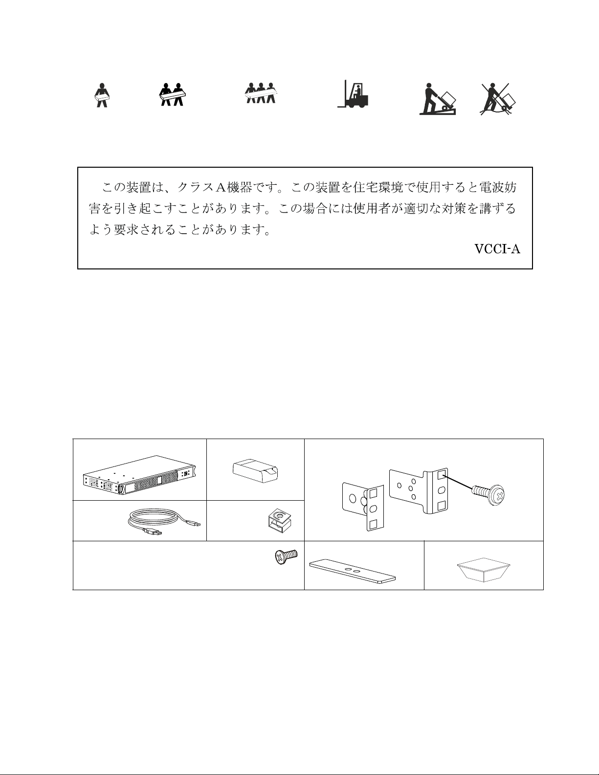
Product Handling Guidelines
su1115a
x4
<18 kg
<40 lb
18-32 kg
40-70 lb
VCCI-A Caution
General information
• The model and serial numbers are located on a small, rear panel label.
• Always recycle used batteries.
• Recycle the package materials or save them for reuse.
32-55 kg
70-120 lb
>55 kg
>120 lb
Package Contents
Inspect the contents upon receipt. Notify the carrier and dealer if the unit is damaged.
UPS Battery
USB cable Cage nuts x4
4 flat head screws to either secure rack-mount brackets
to the UPS or to secure tower feet to the UPS.
• 1 pair rack-mount brackets
• 4 ornamental screws to secure rack-mount brackets to the rack
1 pair tower feet Foot x4
3Smart-UPS SCL400RMJ1U 100 Vac, 400 VA, Tower/Rack-Mount
Page 4

Specifications
s
u
1
1
3
1
a
For additional specifications refer to the APC by Schneider Electric Web site, www.apc.com.
Environmental
Temperature Operating
Storage
Maximum Elevation Storage
Transporting
Operating
Humidity Storage
Transporting
Operating
IP Rating Operating
Note: The recommended recharge interval for this UPS is 12 months.
The transporting conditions are for 2 weeks maximum.
Physical
Follow all lifting guidelines.
Unit weight without packaging
Unit weight with packaging
Unit dimensions without packaging
Height x Width x Depth
Unit dimensions with packaging
Height x Width x Depth
0 °C to 40 °C (32 °F to 104 °F)
-15 °C to 40 °C (5 °F to 104 °F)
0 to 15,000 m
0 to 15,000 m
0 to 3,000 m
0 to 95% non condensing
0 to 95% non condensing
0 to 95% non condensing
IP20
4.0 kg
6.0 kg
44.45 mm (max) x 432 mm x 232 mm
(1.75 in (max) x 17.0 in x 9.2 in)
168 mm x 590 mm x 337 mm
(6.6 in x 23.2 in x 13.3 in)
Product Overview
Front Bezel
Battery door
Battery
QR code for downloading operation manual
Front display panel
Smart-UPS SCL400RMJ1U 100 Vac, 400 VA, Tower/Rack-Mount4
Page 5

Rack-Mount Installation
s
u
1
1
3
3
a
x4
s
u
1
0
9
2
a
s
u
1
0
9
3
a
x4
s
u
1
0
9
4
a
Insert this way
to connect battery
su1112a
s
u
1
1
1
3
a
s
u
1
0
9
5
a
s
u
1
0
9
6
a
CAUTION
RISK OF FALLING EQUIPMENT
• Always practice safe lifting techniques adequate for the weight of the equipment.
• Always use the recommended number of screws to secure brackets to the UPS.
• Always use the recommended number of screws to secure the UPS to the rack.
• Always install the UPS at the bottom of the rack.
Failure to follow these instructions can result in equipment damage and minor or moderate injury
Remove the bezel.
1. Fix the 4 cage nuts (supplied) to the rack.
2. Align the holes on the rack-mount brackets to the holes
where the cage nuts have been fixed.
Push out the battery arresting snaps in the direction of the
arrows.
Secure the rack-mount brackets to the UPS using the 4 flat head
screws supplied.
Secure the UPS onto the rack using the 4 ornamental screws
supplied.
Pull the battery using the flap provided.
Open the battery compartment door by pulling out both the
snaps.
Insert the battery.
5Smart-UPS SCL400RMJ1U 100 Vac, 400 VA, Tower/Rack-Mount
Page 6

Close the battery compartment door and push in both the
s
u
1
0
9
7
a
s
u
1
1
3
4
a
s
u
1
1
3
3
a
s
u
1
1
0
1
a
Insert this way
to connect battery
su1112a
s
u
1
1
1
3
a
s
u
1
1
0
2
a
s
u
1
1
0
3
a
snaps to lock the door.
Fix the front bezel.
Note: Be sure that the flap on the battery is folded and stays
inside the compartment.
Note: Use the flap provided on the battery for pulling the battery out from the battery compartment.
Tower Installation
CAUTION
RISK OF FALLING EQUIPMENT
• Always practice safe lifting techniques adequate for the weight of the equipment.
• Always use the recommended number of screws to secure the tower foot to the UPS.
Failure to follow these instructions can result in equipment damage and minor or moderate injury
Remove the front bezel.
Push out the battery arresting snaps in the direction of the
arrows.
Insert the battery.
Pull both the snaps to open the battery compartment door.
Pull the battery using the flap provided.
Close the battery compartment door and push in both the
snaps to lock the door.
Note: Be sure that the flap on the battery is folded and stays
inside the compartment.
Smart-UPS SCL400RMJ1U 100 Vac, 400 VA, Tower/Rack-Mount6
Page 7

Fix the front bezel.
s
u
1
1
3
5
a
s
u
1
1
3
6
a
x4
su1137a
s
u
1
1
3
2
a
Position the UPS vertically with the front panel display
towards the bottom and fix both the tower feet supplied
using the 4 flat head screws supplied.
Table Mount Foot Installation
1. Orient and place the UPS as shown in the illustration.
2. Locate the foot markings on the base of the UPS.
3. Remove the backing paper from the foot.
4. Stick the four feet to the UPS.
5. Rest the UPS on the table on the four feet.
6. Follow Steps to in Tower Installation to complete the Table Mount Foot Installation.
7Smart-UPS SCL400RMJ1U 100 Vac, 400 VA, Tower/Rack-Mount
Page 8

Operation Manual Link
Refer the link or scan the QR code to access the operation manual.
Link: https://d.go2se.com/SCL400RMJ1U.
Customer support and warranty information are available on the APC by Schneider Electric web site,
www.apc.com.
© 2020 APC by Schneider Electric. APC, the APC logo, and Smart-UPS are owned by
Schneider Electric Industries S.A.S. or their affiliated companies. All other trademarks are property of
their respective owners.
EN 990-6190A
04/2020
 Loading...