

Page 1
MGETM GalaxyTM 9000
50, 60 Hz
800 - 900 kVA
Installation manual
Single-unit UPS
Modular UPS
Parallel UPS with SSC
Frequency converters
Static Switch Cubicle
Page 2

34006451EN/AC - Page 2
Page 3

Contents
1. Characteristics
1.1 Characteristics common to all cubicles ............................................................................................ 4
1.2 Rectifier-inverter cubicle .................................................................................................................... 5
1.3 Static Switch Cubicle ........................................................................................................................... 5
1.4 Electrical parameters for selecting protective devices ................................................................... 6
1.5 Electrical parameters for determining cable cross-sections .......................................................... 7
2. Installation (to be carried out by qualified personnel only)
2.1 Handing .............................................................................................................................................. 10
2.2 Positioning the cubicles .................................................................................................................. 10
2.3 Floor loads (figure 5) ........................................................................................................................11
2.4 Cubicle layout on false floor or normal floor (figures 6, 7, 8) ........................................................11
2.5 Power circuit wiring diagrams ......................................................................................................... 13
2.6 Cubicle mounting and connection ................................................................................................... 17
2.7 Connection of power circuits ........................................................................................................... 19
2.8 Connection of "Media Contacts 9" standard auxiliary circuits (figure 16) ................................... 22
2.9 Connections between cubicles (modular UPSs or parallel UPSs with SSC) .............................. 23
2.10 Connections between rectifier-inverter cubicles and external maintenance bypass cubicle .26
2.11 Connection of "Media Contacts 15" additional auxiliary circuits
(figure 22) ................................................................................................................................... 27
2.12 Connection of the battery "Temperature Monitor" (optional) ...................................................... 28
2.13 Connection of the "LED" remote indications unit ....................................................................... 30
2.14 Connection of "Tele Monitor" remote control and indication unit (option) .............................. 30
2.15 Final installation steps .................................................................................................................. 30
3. Appendix (to be carried out by qualified personnel only)
3.1 Mains 2 line protection ..................................................................................................................... 31
3.2 Cubicle mounting and connection for 2000 kVA Static Switch Cubicle ....................................... 32
3.3 Details of earthing connections in the various cubicles ................................................................ 35
34006451EN/AC - Page 3
Page 4
1. Characteristics
1.1 Characteristics common to all cubicles
TM
MGE
GalaxyTM 9000 UPS: example of a rectifier-inverter cubicle
A
V
k
5
%
12
20
1
.
in
%
M
00
50
1
r
u
0%
Ho
0
1
0
0%
8
%
0
5
VA
0 k
%
0
5
00 40
60
XY
LA
GA
0
IQ
LE
el
AL
v
S
e
l
d
a
o
L
0
e
m
Ti
p
u
ck
a
B
d
le
e
t
b
c
la
e
i
t
a
v
ro
A
p
d
a
o
L
N
5
d
Q
a
e
o
t
L
n
om
e
H
m
ip
qu
e
s
m
r
a
l
A
1
Q
e
n
i
nl
O
1
F
Q
nd
e
r
T
C
l A
a
m
r
s
c
o
i
t
N
is
t
a
t
S
r
fie
ti
ec
R
S
y
r
4
e
Q
tt
a
B
05
20
5/
/0
0
3
er
t
2
r
3
e
C
4:
A
nv
2
I
:
s
5
s
1
a
p
y
B
P
B
s
Q3
s
a
yp
B
t
u
p
t
u
O
p
t u
e
S
Galaxy 6000
m
w
w
w.m
ge
u
ps
.co
H
L
P
0
0
0
VA
6
k
5
y
0%
12
2
1
x
la
a
Min.
0
00%
G
1
our 5
0%
0
H
1
0
%
w
w
80
w
.
m
g
e
u
p
s
.
c
o
m
%
0
5
A
%
0
400 kV
5
0
00
6
Y
AX
AL
G
0
IQ
E
L
vel
SAL
e
ad l
Lo
0
e
m
up Ti
k
c
a
B
d
e
l
e
t
b
a
l
ec
t
o
vai
r
p
A
d
Loa
N
5
Q
ad
o
t
L
n
Home
equipme
s
m
r
a
l
A
Q1
ne
i
l
n
O
1
QF
nd
e
r
T
s
c
i
t
Normal AC
tis
a
t
S
er
i
tif
c
Re
S
ry
4
e
Q
t
t
Ba
05
0
2
/
5
0
0/
3
r
e
t
2
r
3
e
:
4
AC
nv
2
I
15:
ypass
B
BP
s
Q3
s
ypa
B
put
t
u
O
p
u
t
e
S
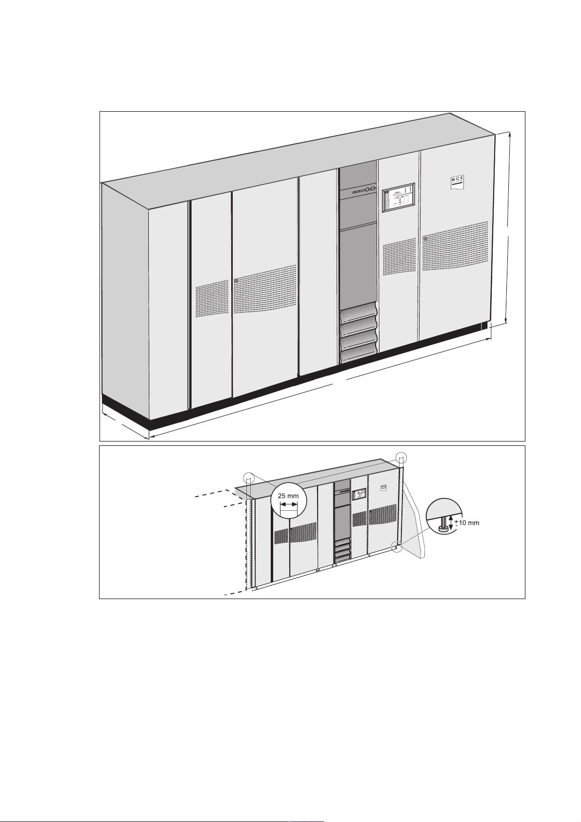
After moving them to their installation location on their pallets, MGE
pallet-mover when the front, rear and side base panels are not mounted. The forks can be inserted from all four sides into 100 mm ±10 mm
TM
GalaxyTM 9000 cubicles can be moved short distances using a forklift or
high openings;
the unadjusted cubicle height (H) is 1900/2000 mm; after lifting the cubicle, the height can be adjusted ±10 mm by screwing in or out the four
feet;
the bearing surface corresponds to the area of the four cylindrical foot pads (60 mm diameter) positioned in each corner
of the cubicle;
the cubicle depth (D) is 840 mm (800 mm without doors and panels);
operating temperature range for rectifier-inverter, frequency converter or Static Switch Cubicles: 0 °C to 35 °C at rated output (40 °C for a
maximum of 8 hours) and 30 °C maximum for overload conditions. Operation outside the specified temperature range will reduce service life;
relative humidity: 95 % maximum;
maximum operating altitude without derating: 1000 m;
connection via the bottom for rectifier-inverter cubicles, or via the top with the addtion of an optional duct that can be installed on the right side
of the cubicle. The auxiliary and Static Switch Cubicles are designed for connections via the top
or bottom.
the connection cables may be run in three ways:
in a trench running under the cubicles,
under a false floor,
on the floor under the cubicles, in the free space equal to the height of the feet; in this case the cables should be run side by side to avoid
blocking the flow of air for ventilation.
the intercubicle connection cables are not supplied (except for the wires for auxiliary interconnections);
normally the cubicles do not have to be secured to the floor; the footpads nevertheless have holes with an average depth of 12 mm designed
for the fitting of M16 anchor bolts;
the cubicle doors are secured by Ronis locks (key 405).
34006451EN/AC - Page 4
Page 5
1.2 Rectifier-inverter cubicle
The parameters given in the table opposite can be used to determine the required rating of a single-unit or modular UPS, a
frequency converter, or a parallel UPS with SSC.
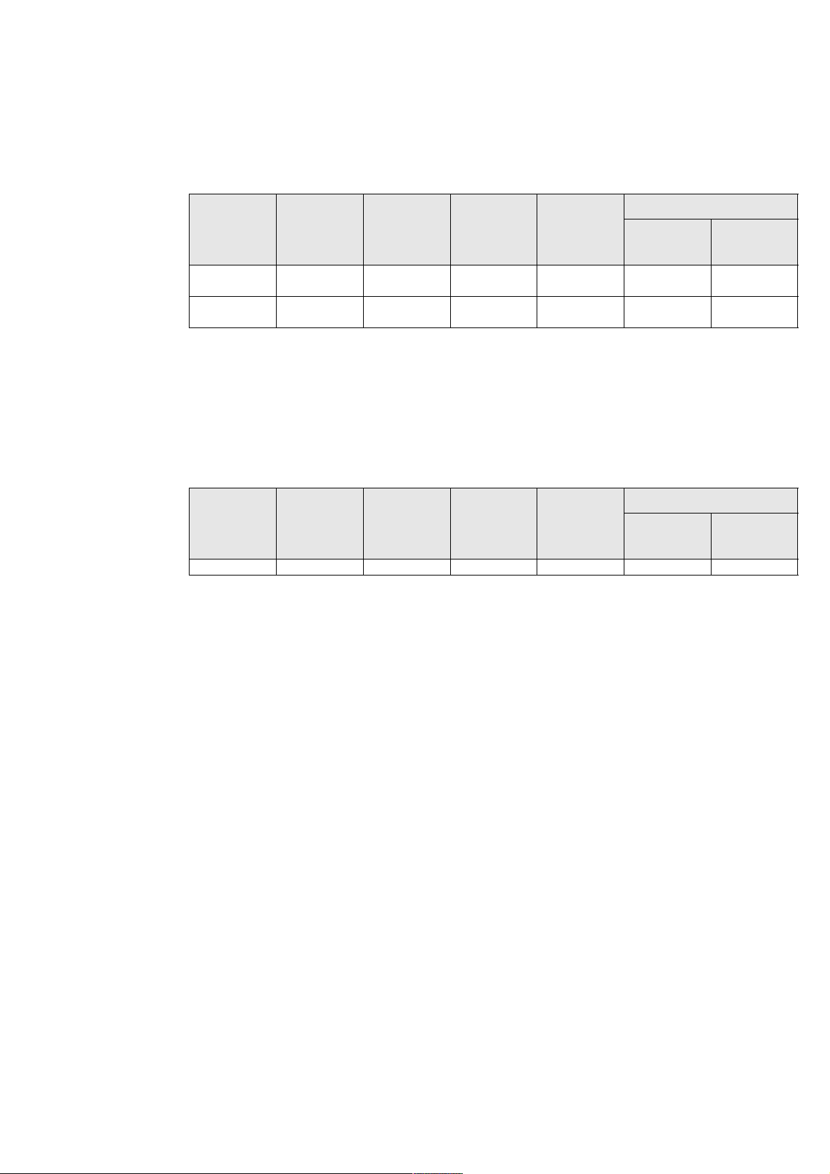
Characteristics of rectifier-inverter cubicles
Characteristics
rated
inverter
output
in kVA
800 3600 ±10 2000 840 4260 47 11233
900 3600 ±10 2000 840 4260 47 11233
(1) the width of the vertical side clearance bars (25 mm) on each side must be added to the indicated cubicle width, i.e. 50 mm in
all per cubicle. This applies to all cubicle installation cases. Cubicle widths have been rounded off to the nearest cm.
(2) the indicated heat losses are those produced by the unit at full rated load and with the battery float charging. They must be
taken into account when dimensioning the air conditioning system. The cubicles are cooled by forced ventilation.
The air enters via the doors and grids at the bottom and is discharged via the roof.
1.3 Static Switch Cubicle
Characteristics of Static Switch Cubicles
rated
SSC
output
in kVA
2000 2450 ±10 1900 ±10 840 1710 < 0.5 < 120
(1) 25 mm must be added on each side to the indicated cubicle width, i.e. 50 mm in all per cubicle. This applies to all cubicle
installation cases. Cubicle widths have been rounded off to the nearest cm.
(2) the indicated heat losses are those produced by the unit at full rated load when operating on Mains 2. They are not to be taken
into account when dimensioning the air conditioning system. The cubicles are cooled by forced ventilation.
cubicle
width W
in mm (1)
cubicle
width W
in mm (1)
cubicle
height H
in mm
cubicle
height H
in mm
cubicle
depth D
in mm
cubicle
depth D
in mm
maximum
weight
in kg
maximum
weight
in kg
heat losses (2)
in kW in cal./s
heat losses (2)
in kW in cal./s
34006451EN/AC - Page 5
Page 6
Characteristics
1.4 Electrical parameters for selecting protective devices
The parameters given in the table below can be used to determine the required rating of the source side protective circuit
breaker on Mains 1 of a single-unit or modular UPS, a frequency converter, or a parallel UPS with SSC.
Important:
It is essential to choose the type of circuit breaker according to its breaking capacity and the prospective short-circuit current
at its place of installation.
Note:
For Mains 1 power supply voltages of 380, 400 and 415 V, the Mains 1 current is the same because it is a function
of the DC voltage.
Electrical parameters for Mains 1
rated
inverter
output
in kVA
800 1555 1329 1819 2183
900 1555 1329 1819 2183
(1) the rated Mains 1 currents (In) have been determined for a rated phase-to-phase voltage of 380 V to 415 V, a battery with a
15 minute backup time (206 cells at 2 V per cell, i.e. 412 V) and at the beginning of its recharge cycle, and full rated load with a
power factor of 0.9.
(2) the rated Mains 1 currents (In) have been determined for a minimum float charging voltage of 423 V and full rated load with
a power factor of 0.9.
(3) the Mains 1 currents given for an overload of 25 % or 50 % are maximum values. They have been determined for a battery
drawing the minimum float charging voltage and a load power factor of 0.9. When choosing the circuit breaker rating, use the
"rated current" column and check that the circuit breaker tripping curves are compatible with the values in the overload columns.
The parameters given in the table below can be used to determine the required rating of the source side protective circuit
breaker on the Mains 2 line for a single-unit or modular UPS.
Important:
– It is essential to choose the type of circuit breaker according to its breaking capacity and the prospective short-circuit current
at its place of installation.
This choice must also be made so as to protect the static switch semiconductors and ensure discrimination with respect to
the UPS output fuses (refer to "appendix" chapter).
– For an installation with a Static Switch Cubicle, the Mains 2 currents indicated in the table must be multipled by the number
of parallel-connected rectifier-inverter cubicles required to supply the load power (i.e. without taking redundant rectifierinverter units into account).
Remark:
If the installation includes a transformer on the Mains 2 input, allow for the inrush current caused by magnetization of the
transformer windings.
Mains 1 current
rated current In for unit: for 25 %
with battery at start
of charge cycle (1)
without battery (2)
overload (3)
for 50 %
overload (3)
Electrical parameters for Mains 2 (415 V)
rated
inverter
output
in kVA
800 1155 1444 1733
900 1299 1624 1949
(1) the Mains 2 currents have been determined for a rated phase-to-phase voltage of 415V, a load power factor of 0.9 and for full
rated load as well as overloads of 25 % or 50 %. When choosing the circuit breaker rating, use the "rated curent" column and check
that the circuit breaker tripping curves are compatible with the data in the overload columns.
For a Mains 2 voltage of 380 V, multiply the currents indicated in this table by 1.09.
For a Mains 2 voltage of 400 V, use the table in another language version of this manual.
Mains 2 current (1)
rated current In for 25 %
overload
for 50 %
overload
34006451EN/AC - Page 6
Page 7
1.5 Electrical parameters for determining cable cross-sections
– this table has been drawn up for rated phase-to-phase Mains and load voltages of 415 V. For voltages of 380 V, multiply
the currents for Mains 2 and load by 1.09; for voltages of 400 V, use the table in another language version of this manual;
– the current values and cable cross-sections for Mains 1 are given for full rated load with a power factor of 0.9 and a battery
consuming its minimum float charging voltage;
– the battery current values and cable cross-sections have been determined for a battery at the end of a charge cycle;
– the current values and cable sections for Mains 2 and load are given for full rated load with a power factor of 0.9.
For frequency converters, the parameters concerning Mains 2 are not applicable.
The load parameters common to all the converters are given in the table below.
For a parallel UPS, the parameters for Mains 2 and load are also provided in the table below.
For a modular UPS, the parameters for Mains 2 and load are also provided in the table below.
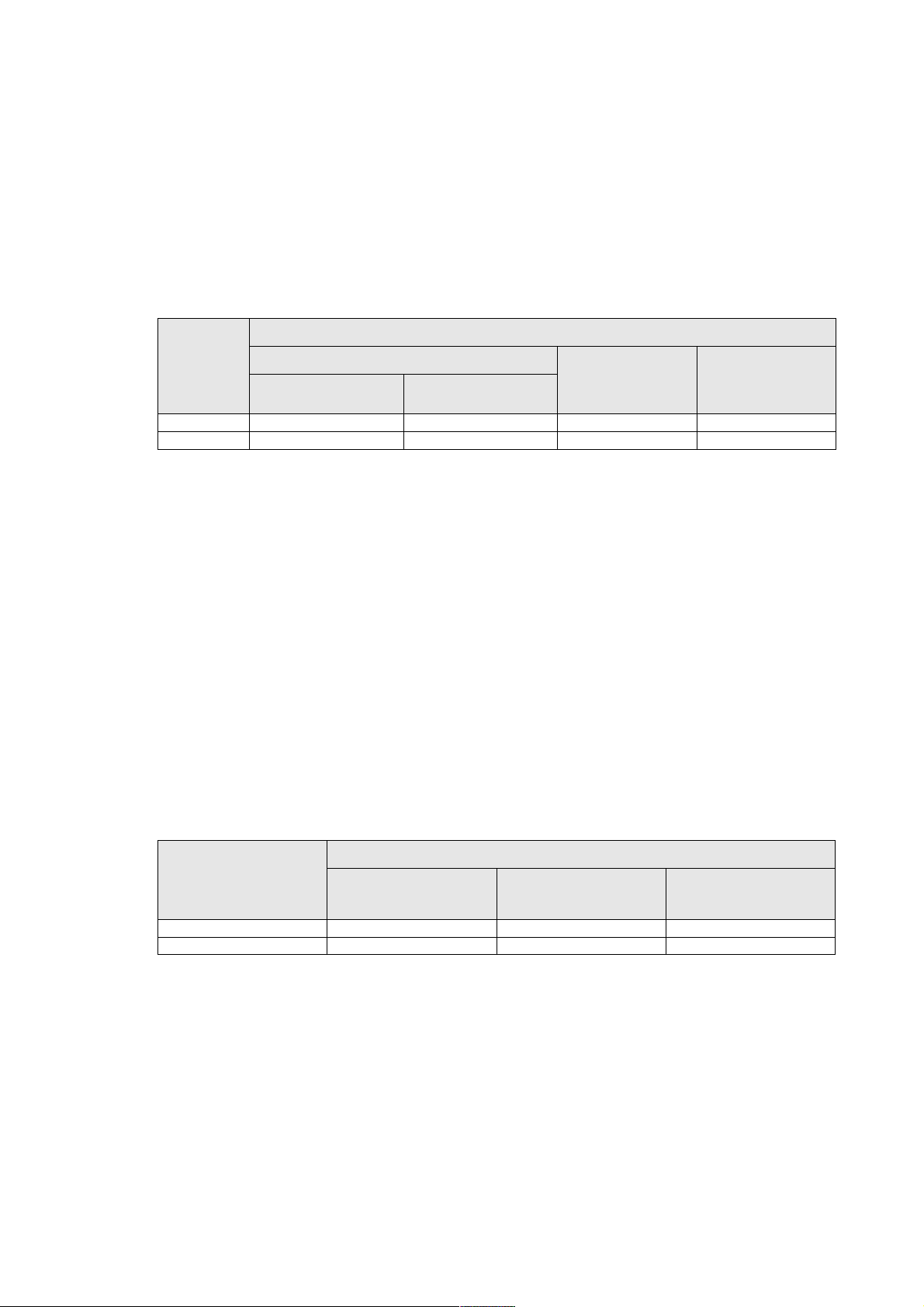
Parameters for single-unit UPS cables
Copper conductors
rated
inverter
output
in kVA
800 1455 1155 2274 4 x 240 4 x 185 3 x 240
line currents absorbed in Amps cross-sectional area of cables in mm2 (2)
Mains 1 415 V
with or
without
battery (1)
Mains 2
and load
battery Mains 1 415 V
with or
without
battery (1)
Characteristics
battery
Mains 2
and load
900 1455 1299 2274 4 x 240 4 x 240 3 x 240
Aluminium conductors
rated
inverter
output
in kVA
800 1455 1155 2274 4 x 400 4 x 300 3 x 400
900 1455 1299 2274 4 x 400 4 x 400 3 x 400
(1) the rated Mains 1 currents (In) have been determined for a minimum float charging voltage of 423 V and full rated load with a
power factor of 0.9.
(2) the cable cross-sections are calculated according to permissible temperature rise and allow for line voltage drops over a
maximum length of 100 m (AC circuits) or 25 m (DC circuits if cables not provided). For greater lengths, the cross-sections should
be chosen to limit voltage drops to 3 % (AC)
or 1 % (DC).
line currents absorbed in Amps cross-sectional area of cables in mm2 (2)
Mains 1 415 V
with or
without
battery (1)
Mains 2
and load
battery Mains 1 415 V
with or
without
battery (1)
Mains 2
and load
battery
34006451EN/AC - Page 7
Page 8

Characteristics
The table below serves as an example for an installation comprising up to four frequency converters or four parallel UPSs
with a centralised SSC.
– for installations with redundant units, take into account only the units required to supply the load power
(e.g. for an installation made up of 3 parallel-connected rectifier-inverter cubicles, one being redundant, only 2 rectifierinverter cubicles are used to determine Mains 2 and load currents and cable cross-sections);
– this table has been drawn up for rated phase-to-phase Mains 2 and load voltages of 415 V and full rated load with a power
factor of 0.9. For voltages of 380 or 400 V, multiply the indicated currents by 1.09 and 1.04 respectively, then modify the cable
cross-sections accordingly if necessary.
The cable cross-sections in this table are for the parts illustrated in bold on the following block diagrams (installation examples,
figures 1 and 2).
Parameters for Mains 2 and load cables for an installation comprising frequency converters or parallel
UPSs with a centralised SSC.
rated
inverter
output
number of
parallel-connected
inverters
total UPS
rated output
in kVA
Mains 2 or load
line current
in Amps
cable
cross-section (1)
in mm²
in kVA
800 2 1600 2310
3 2400 3465
4 3200 4620
900 2 1800 2598
3 2700 3897
4 3600 5196
(1) cable cross-sections are given for copper conductors of the U1000 R02V type (increase by 30 % for aluminium conductors).
They are calculated according to permissible temperature rise and allow for line voltage drops over a maximum length of 100 m.
For greater lengths, the cross-sections should be chosen to limit voltage drops to 3 %.
Please consult us*
Please consult us*
Please consult us*
Please consult us*
Please consult us*
Please consult us*
* NF C 15-100 authorizes a maximum of 4 cables per phase.
Installation with parallel frequency converters I
mains 1
mains 1
mains 1
inverter 1
inverter 2
inverter 3
load
Fig. 1
Installation with parallel UPSs with a centralised SSC
mains 2
mains 1
mains 1
mains 1
Fig. 2
inverter 1
inverter 2
inverter 3
static
switch
cubicle
load
34006451EN/AC - Page 8
Page 9

Characteristics
The table below serves as an example for an installation with up to four modular UPSs with an external maintenance bypass.
– for installations with redundant units, take into account only the units required to supply the load power
(e.g. for an installation made up of 3 parallel-connected rectifier-inverter cubicles, one being redundant, only 2 units are used
to determine the currents on the maintenance bypass line and the load, and the cross-sectional areas of cables);
– this table has been drawn up for rated phase-to-phase Mains 2 and load voltages of 415 V and full rated load with a power
factor of 0.9. For voltages of 380 or 400 V, multiply the indicated currents by 1.09 and 1.04 respectively, then modify the cable
cross-sections accordingly if necessary.
The cable cross-sections in this table are for the parts illustrated in bold on the following block diagrams (installation example,
figure 3);
– important. In an installation with an external maintenance bypass, the power cables between each UPS and the
upstream protection devices must be the same length. The same holds for the power cables between each UPS cubicle
and the external maintenance bypass.
rated
inverter
output
number of
parallel-connected
inverters
total UPS
rated output
in kVA
mains 2 or load
line current
in Amps
cable
cross-section (1)
in mm²
in kVA
800 2 1600 2310
Please consult us*
3 2400 3465 Please consult us*
4 3200 4620 Please consult us*
900 2 1800 2598 Please consult us*
3 2700 3897 Please consult us*
4 3600 5196 Please consult us*
(1) cable cross-sections are given for copper conductors of the U1000 R02V type (increase by 30 % for aluminium conductors).
They are calculated according to permissible temperature rise and allow for line voltage drops over a maximum length of 100 m.
For greater lengths, the cross-sections should be chosen to limit voltage drops to 3 %.
* NF C 15-100 authorizes a maximum of 4 cables per phase.
Installation comprising modular UPSs with an external maintenance bypass
maintenance Bypass cubicle
mains 1
mains 2
mains 1
mains 2
mains 1
mains 2
inverter 1
inverter 2
inverter 3
load
Fig. 3
34006451EN/AC - Page 9
Page 10
2. Installation (to be carried out by qualified personnel only)
2.1 Handing
Unpacked cubicles may be moved using a forklift from the front or from the back. Distances must not exceed a few meters.
2.2 Positioning the cubicle
– prior to moving the cubicles to their final position, remove the packing material and withdraw the base panels from the space
on the side created by the spacing uprights. The panels will be installed at the end of the installation procedure;
– spacing uprights on the sides of the cubicles create a 50 mm clearance when cubicles are positioned next to each other,
enabling users to open the doors (see figure 4). If a cubicle is installed next to a wall, leave additional space so that the cubicle
is 50 mm from the wall;
– when the spacing uprights are not required (cubicles are not positioned next to a wall or another cubicle), they may be
removed:
– loosen the four screws securing the upright,
– lift the upright and pull it free,
– replace the long gold-coloured screws with the black screws supplied in a bag attached to the cable terminals in the cubicle;
– adjust the height of the feet until the first cubicle is perfectly vertical; adjust the feet of the subsequent cubicles so that the
all the doors are perfectly aligned.
Side clearances provided by the spacing uprights
rear
s
50
50
Fig. 4
front
cubicle 1
spacing uprights
of cubicle 1
cubicle 2
spacing uprights
of cubicle 2
34006451EN/AC - Page 10
Page 11
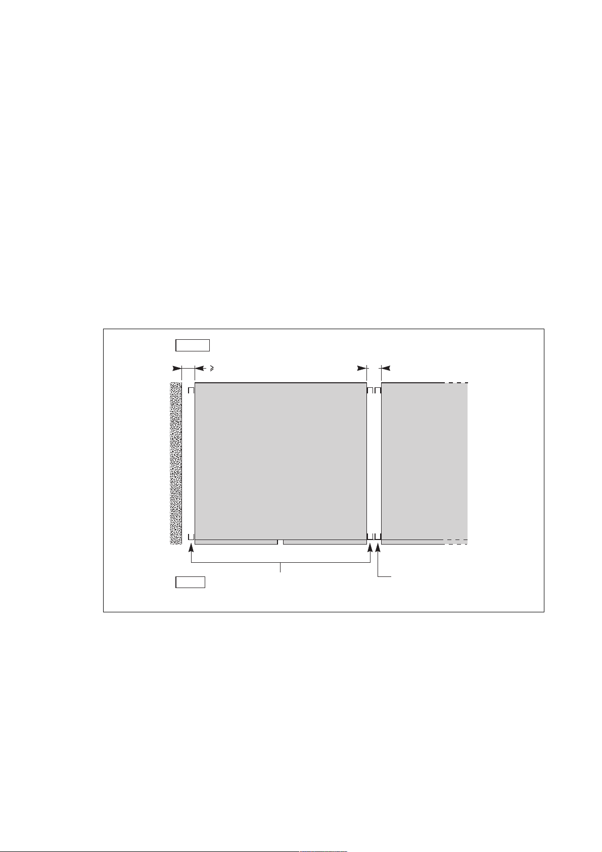
2.3 Floor loads (figure 5)
– the floor supports the weight of each cubicle via the four 60 mm diameter pads at the bottom of the feet screwed into the
corners of the frame;
– the exact locations of the footpads are indicated in the figure;
– normally the cubicles do not have to be secured to the floor; the footpads nevertheless have holes with an average depth
of 12 mm designed for the fitting of M16 anchor bolts;
– to determine the stresses applied by the cubicle feet on the floor, divide the cubicle weight (see the first 3 tables of this
manual) by the total area of the 4 footpads (110 cm
Cubicle footpads
Installation
2
).
rear
four 60 mm dia.
footpads with
12 mm average
depth holes for
M16 anchor bolts
33 33
33
736
cubicle width
less 66 mm
front
Fig. 5
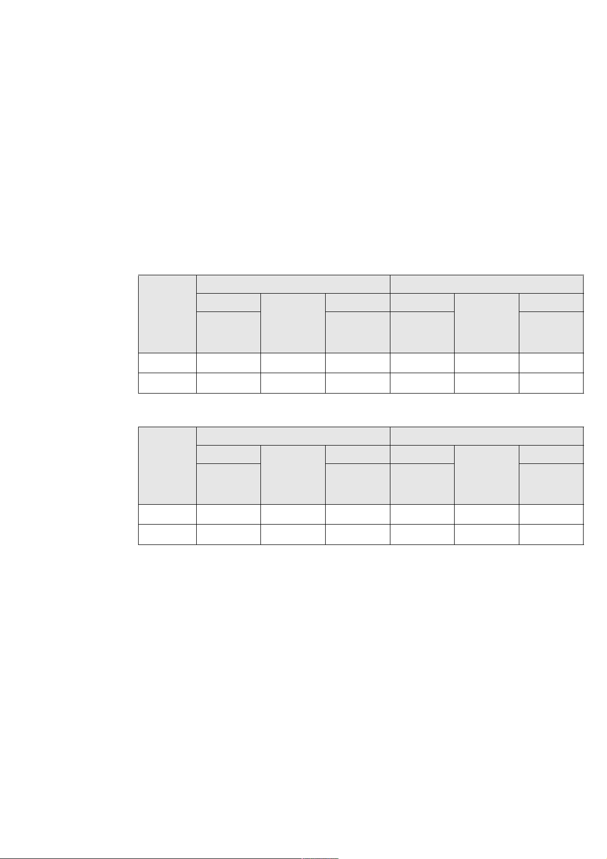
2.4 Cubicle layout on false floor or normal floor (figures 6, 7, 8)
– the cubicles can be installed directly up against the rear wall;
– an overall clearance of 400 mm must be left above the entire surface of the cubicles for ventilation;
– a side clearance of 25 mm is provided by the vertical bars on the sides of the cubicles to allow door opening. For cubicles
mounted side by side, the two adjacent bars ensure an inter-cubicle clearance of 50 mm;
– a minimum clearance of 1000 mm is required in front of the cubicles to allow complete opening of the doors and easy
access for maintenance work (replacement of subassemblies);
– for extended battery backup times or high output systems, the UPS may have several battery cubicles (see the table at the
end of the previous chapter). If this is the case, install the battery cubicles on the left side of the rectifier-inverter cubicle with
the cubicle containing the battery circuit breaker QF1 closest to the rectifier-inverter cubicle (figure 7);
– when an auxiliary cubicle is included in the UPS, it should be installed to the left of the battery cubicle(s);
connection via the bottom
The connection cables may be run in three ways:
– in a cable trench running underneath the front of the cubicles (see trench dimensions and layout in figure 6),
– under a false floor. A cutout must in this case be made in the floor for cable entry (see figure 6 for dimensions),
33
3333
34006451EN/AC - Page 11
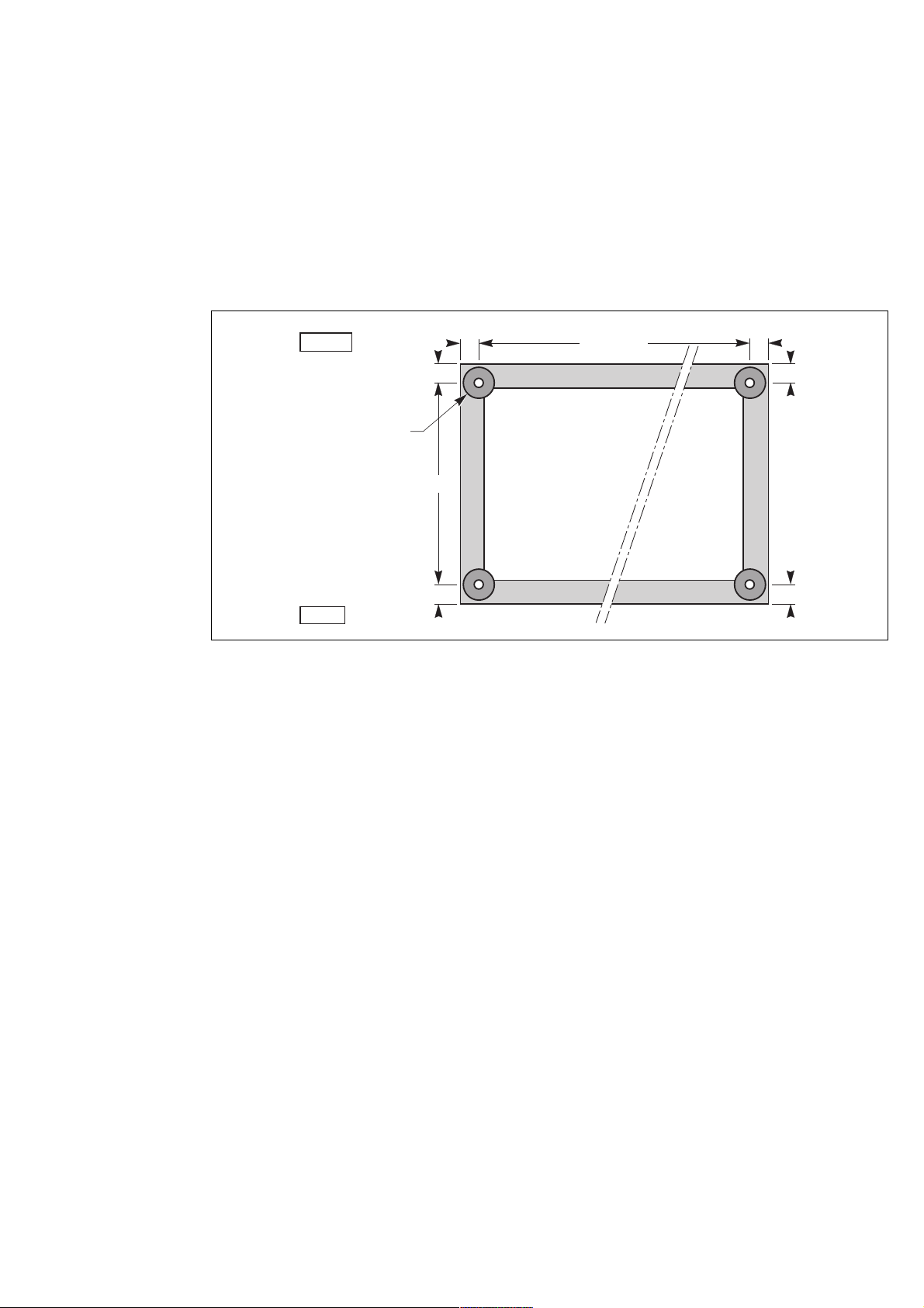
Page 12
Installation
Layout for a single-unit UPS with one battery cubicle
rear
>25
80
cubicle width W
(see table)
battery cubicle
50
cubicle width W
(see table)
rectifier-inverter cubicle
spacing uprights
front
cutouts necessary for
cable entry from underneath
a false floor:
200 mm x (W 160 mm)
Fig. 6
Layout for a single-unit UPS with several battery cubicles
rear
battery cubicle 1
battery cubicle 2
containing battery
circuit breaker QF1
can equal 0
800
> 1000
rectifier-inverter cubicle
location
of trench
under cubicles
(if applicable)
front
Fig. 7
– on the floor under the cubicles, in the free space equal to the height of the feet. In this case the cables should be run side
by side to avoid blocking the flow of air for ventilation. The cables exit from the rear or sides of the cubicles;
connection via the top
– the Static Switch, filter and auxiliary cubicles are designed for connection via the bottom or top,
– for the rectifier-inverter cubicles, a special 400 mm wide connection duct must be added to the right of the cubicle to allow
connection via the top.
Layout for an installation with two parallel UPSs and a centralised SSC
rear
front
auxiliaries
cubicle 2
(if applicable)
battery
cubicle(s) 2
rect./inv.
cubicle 2
auxiliaries
cubicle1
(if applicable)
battery
cubicle(s) 1
rect./inv.
cubicle 1
static switch
cubicle
34006451EN/AC - Page 12
Fig. 8
Page 13
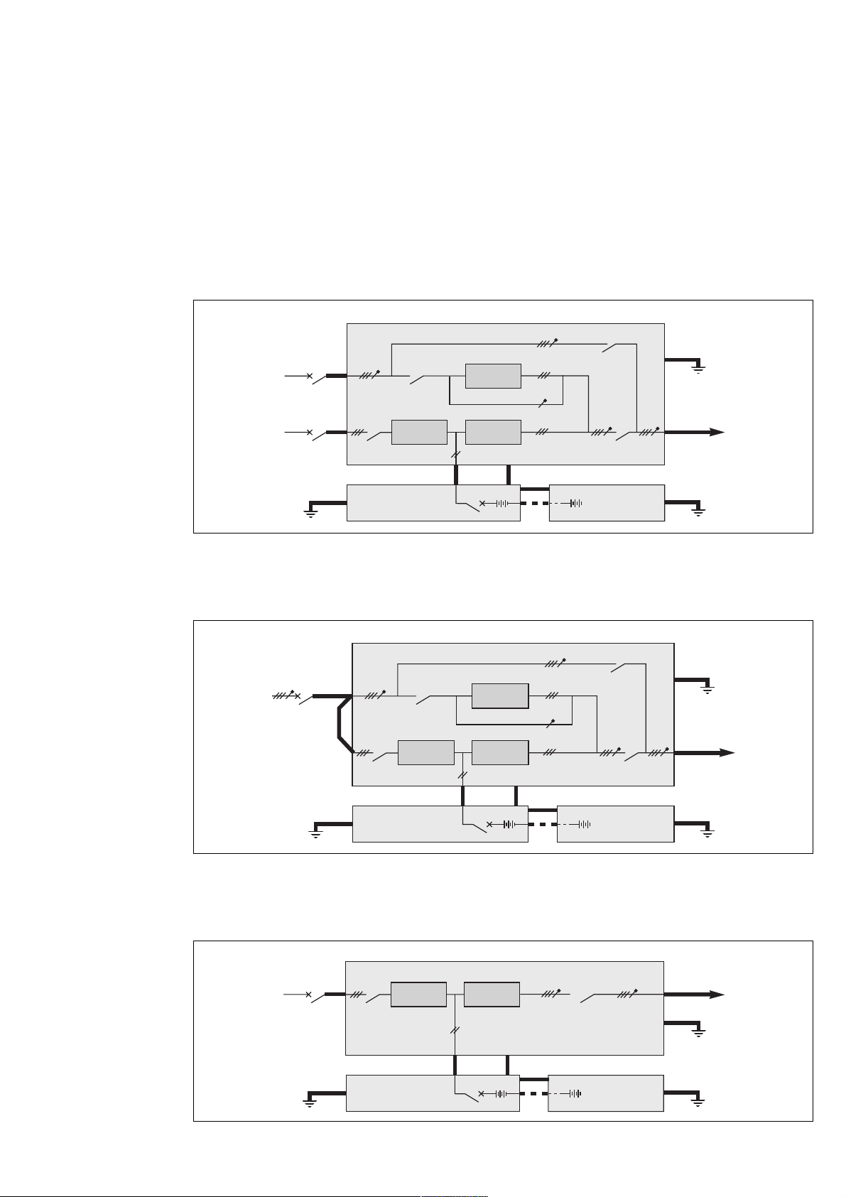
2.5 Power circuit wiring diagrams
The single-wire diagrams for typical UPS installations are given in figures 9 to 15. The heavy lines represent the cables that
must be connected
(see the table in the previous chapter for the required cross-sectional areas of the cables).
Note:
– for frequency converters, the input and output frequencies may be different (50 or 60 Hz);
– for frequency converters without batteries, ignore the battery cubicles and the + and - cables shown in the diagram.
Special case:
The UPSs can be optionally supplied with the neutral conductor not interrupted by switches Q4S, Q3BP and Q5N.
Diagram for a single-unit or single modular UPS with common Mains 1 and 2
rectifier-inverter cubicle
Installation
Q3BP
mains 2
mains 1
earth
Q1 Q5N
battery cubicle
beside the
rectifier-inverter cubicle
Q4S
rectifier
charger
QF1
static
switch
inverter
+
frames interconnections for earthing
other battery
-
+
-
cubicles (if
applicable)
Fig. 9
Diagram for a single-unit or single modular UPS with common Mains 1 and 2
rectifier-inverter cubicle
Q3BP
mains
mains 2
input
mains 1
input
Q1 Q5N
Q4S
rectifier
charger
static
switch
inverter
earth
load
earth
earth
load
earth
battery cubicle
beside the
rectifier-inverter cubicle
QF1
Fig. 10
Diagram for a frequency converter with batteries
rectifier-inverter cubicle
mains 1
earth
Fig. 11
Q1 Q5N
rectifier
charger
battery cubicle
beside the
rectifier-inverter cubicle
inverter
QF1
frames interconnections for earthing
other battery
+
-
frames interconnections for earthing
+
-
+
+
-
cubicles (if
applicable)
other battery
-
cubicles (if
applicable)
earth
load
earth
earth
34006451EN/AC - Page 13
Page 14

Installation
Diagram for a frequency converter without batteries
rectifier-inverter cubicle
mains 1
Q1 Q5N
rectifier
charger
inverter
Fig. 12
Example of a 2 parallel UPS rectifier-inverters with SSC
Static Switch Cubicle
Q3BP
mains 2
rectifier-inverter cubicle 1
mains 1
Q4S
Q1 Q5N
rectifier
charger
static
switch
inverter 1
frames interconnection for earthing
Q5N
load
earth
load
inverter 1
output
earth
earth
frames interconnections for earthing
earth
mains 1
earth
battery cubicle
beside rectifierinverter cubicle 1
rectifier-inverter cubicle 2
Q1 Q5N
rectifier
charger
battery cubicle
beside rectifierinverter cubicle 2
QF1
inverter 2
QF1
+
-
frames interconnections for earthing
frames interconnections for earting
+
-
+
+
other battery
-
cubicles (if
applicable)
other battery
-
cubicles (if
applicable)
inverter 2
output
earth
earth
earth
Fig. 13
Note:
Both the rectifier-inverter cubicles and the Static Switch Cubicle can be supplied from a common Mains, in which case there
is only one upstream circuit breaker (same as the case of a single-unit UPS with a common Mains 1 and 2).
34006451EN/AC - Page 14
Page 15

Example of 2 multi-bypass modular UPS cubicles for redundancy
modular UPS cubicle 1
Q3BP
Installation
earth
mains 2
mains 1
earth
mains 2
mains 1
Q4S
Q1 Q5N
rectifier
charger
battery cubicle
beside rectifierinverter cubicle 1
modular UPS cubicle 2
Q4S
Q1 Q5N
rectifier
charger
static
switch
inverter 1
QF1
static
switch
inverter 2
frames interconnection for earthing
+
-
Q3BP
+
frames interconnection for earthing
other battery
-
cubicles (if
applicable)
inverter 1
output
earth
earth
inverter 2
output
load
Fig. 14
earth
battery cubicle
beside rectifierinverter cubicle 2
QF1
frames interconnection for earthing
other battery
+
-
+
-
cubicles (if
applicable)
earth
34006451EN/AC - Page 15
Page 16
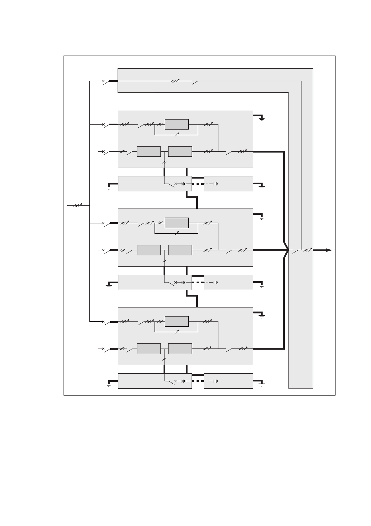
Installation
Example of an installation comprising three modular UPSs with an external maintenance bypass
External
maintenance
bypass line
mains 2
mains 1
earth
mains 2
mains 1
External maintenance bypass cubicle
Q3BP
modular UPS cubicle 1
Q4S
Q1 Q5N
rectifier
charger
battery cubicle
beside rectifierinverter cubicle 1
modular UPS cubicle 2
Q4S
Q1 Q5N
rectifier
charger
static
switch
inverter 1
QF1
static
switch
inverter 2
frames interconnection for earthing
+
-
frames interconnection for earthing
+
other battery
-
cubicles (if
applicable)
earth
earth
earth
Q5N
load
frames interconnection for earthing
earth
mains 2
mains 1
earth
battery cubicle
beside rectifierinverter cubicle 2
modular UPS cubicle 3
Q4S
Q1 Q5N
rectifier
charger
battery cubicle
beside rectifierinverter cubicle 3
QF1
static
switch
inverter 3
QF1
+
-
frames interconnection for earthing
frames interconnection for earthing
+
-
+
+
other battery
-
cubicles (if
applicable)
other battery
-
cubicles (if
applicable)
earth
earth
earth
Fig. 15
Important. The power cables between each UPS and the upstream protection devices must be the same length. The
same holds for the power cables between each UPS cubicle and the external maintenance bypass.
34006451EN/AC - Page 16
Page 17
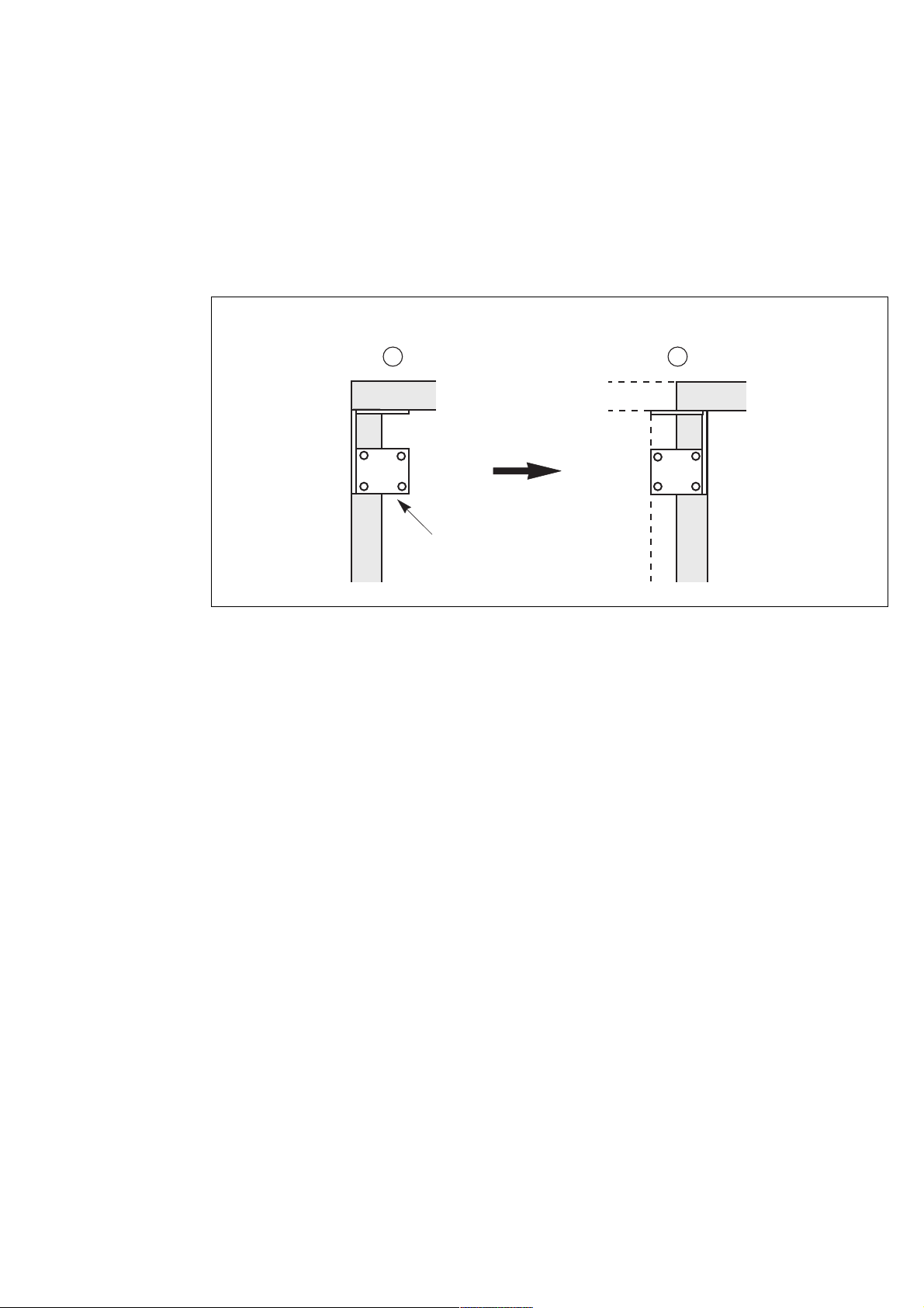
2.6 Cubicle mounting and connection
Mounting of the left and right cubicles
Gusset plates have been fitted to the top corners on all four sides of the cubicles to provide reinforcement for transportation.
– prior to joining the two cubicles, remove the rear gusset from the right side of the left cubicle;
– move the cubicles to their operating location;
– adjust the front foot pads so that the cubicles are vertical and their doors aligned;
– remove the top panel on the left side of the right cubicle for access to the side gussets (see figure opposite);
– remove the rear double gusset on the right cubicle, turn it around and bolt the two cubicles together.
right cubicle
A B
Installation
double gusset
to be
turned around
34006451EN/AC - Page 17
Page 18
Installation
Internal connections between cubicles
– removal of inverter leg no.6 is recommended prior to bolting fish-plates L+ and L-;
– first remove the two fuses and the two cables connected to the leg;
– then pull the leg out;
– bolt fish-plates L+ and L-;
– refit inverter leg no 6;
– intended only for transportation, the front gussets do not need to be refitted;
– bolt cables L1, L2, L3 and N (4 x 2) coming from the left cubicle to the bars in the right cubicle (see figure opposite);
– connect the earth strap to the front uprights of both cubicles;
– connect the connectors marked XF286 to XF2810 on the five ribbon cables coming from the right cubicle to connectors
XM286 to XM2810 respectively on the interface board located on the right side of the left cubicle;
– connect the connectors marked XFGD01 to XFGD05 (XFGD01 to XFGD05 and XMGD06 for parallel UPSs) on the control
wires coming from the left cubicle to connectors XMGD01 to XMGD05 (XMGD01 to XMGD05 and XFGD06 for
parallel UPSs).
right cubicle
fuses and cables
to be disconnected
inverter
leg no. 6
interface board
XM286 to XM2810
XMGD01 to XMGD04
XFGD06
earth strap to be
connected to the front
uprights of both cubicles
XMGD05
L
fish-plates
to be
bolted
L+
cables to be
connected
N L1 L2 L3
left cubicle
34006451EN/AC - Page 18
Page 19

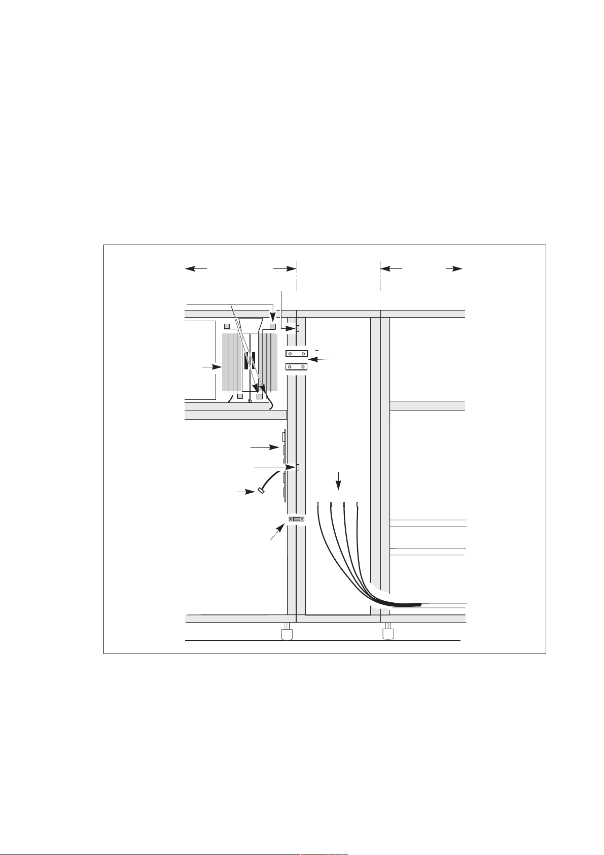
2.7 Connection of power circuits
Before making connections, check that switches Q1, Q4S, Q3BP and Q5N are in the "open" position (toggle opposite the "O"
mark).
General:
– in the case of parallel-connected rectifier-inverter cubicles with SSC, switches Q4S and Q3BP are not included and
mains 2 is connected to the Static Switch Cubicle. The other connections are the same;
– for modular UPSs with an external maintenance bypass, switch Q3BP must be locked open;
– the power cables for the connections between cubicles are not supplied;
– open the doors and remove the lower terminal shields (secured by screws to the cubicle chassis) of the rectifier-inverter
and Static Switch Cubicles;
– connect the cables shown in heavy lines in the wiring diagrams shown previously to the terminals specified in the figures
below;
– each cubicle must be earthed;
– the routing of the power cables is shown in the figures;
– the auxiliary wiring is routed in troughs located nearby (not shown in the drawings);
– outside the cubicles, separate the auxiliary wiring from the power cables;
– all the cubicles must be interconnected for earthing, forming a mesh which is itself connected to the building structure and
earthing electrode;
– the connection drawings hereafter show the cubicles with doors open and terminal shields removed.
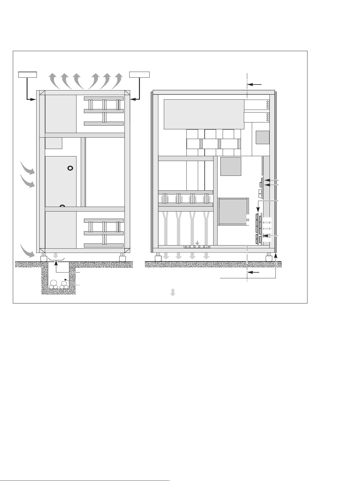
Left cubicle of single-unit or parallel UPS with SSC
installation
cross-section AA
air
admission
battery
mains 1
air
admission
air extraction
transformer
rearfront
front view
rectifier
charger
inverter
stack
off
on
L1
mains 1
A
inverter
stack
FHCZ
board
Q1
L2
L3
inverter
stack
L+
battery
L
cable tie bar
connection
from below
trough (if applicable)
spacing
uprights
cable
tie bar
power cable routing
via the bottom
Cables connected by lugs to 100 x 8 mm copper terminals and 13 mm diameter holes.
Height of connections relative to floor:
– mains 1: 450 mm;
– battery: 480 mm.
A
34006451EN/AC - Page 19
Page 20

Installation
Right cubicle of single-unit UPS
cross-section AA front view
air extraction
rearfront
A
air
admission
mains 2,
load
air
admission
card
cage
transformer
cable tie bar
card
cage
remote relay
board
off
on
XR1
XR2
XR3
XR4
inverter
stack
XR8
XR9
XR5
XR6
XR7
additional remote
relay board (optional)
Q4S
off
on
L1 L2 L3N
mains 2
inverter
stack
Q3BP
inverter
stack
off
Q5N
on
L1 L2 L3N
load
connection
from below
trough (if applicable)
earth
bar
cable
tie bar
power cable routing via the bottom
Cables connected by lugs to 100 x 8 mm copper terminals and 13 mm diameter holes.
Height of connections relative to floor:
– mains 2 and load: 430 mm;
– remote relay board: 1030 mm.
A
spacing
uprights
34006451EN/AC - Page 20
Page 21

Right cubicle of a parallel UPS with SSC
Installation
cross-section AA front view
air extraction
front
air
admission
card
cage
transformer
rear
XM133
ACPZ
board
XM136
XM137
card
cage
APOZ
board
XR1
XR2
XR3
XR4
inverter
stack
XR8
XR9
XR5
XR6
XR7
inverter
stack
remote relay board
remote relay board
A
inverter
stack
off
Q5N
on
load
air
admission
cable tie bar
connection
from below
trough (if applicable)
earth
bar
power cable routing via the bottom
Cables connected by lugs to 100 x 10 mm copper terminals and 14 mm diameter holes.
Height of connections relative to floor:
– load: 410 mm;
– remote relay board: 1030 mm.
cable
tie bar
L1 L2 L3N
load
A
spacing
uprights
34006451EN/AC - Page 21
Page 22
Installation
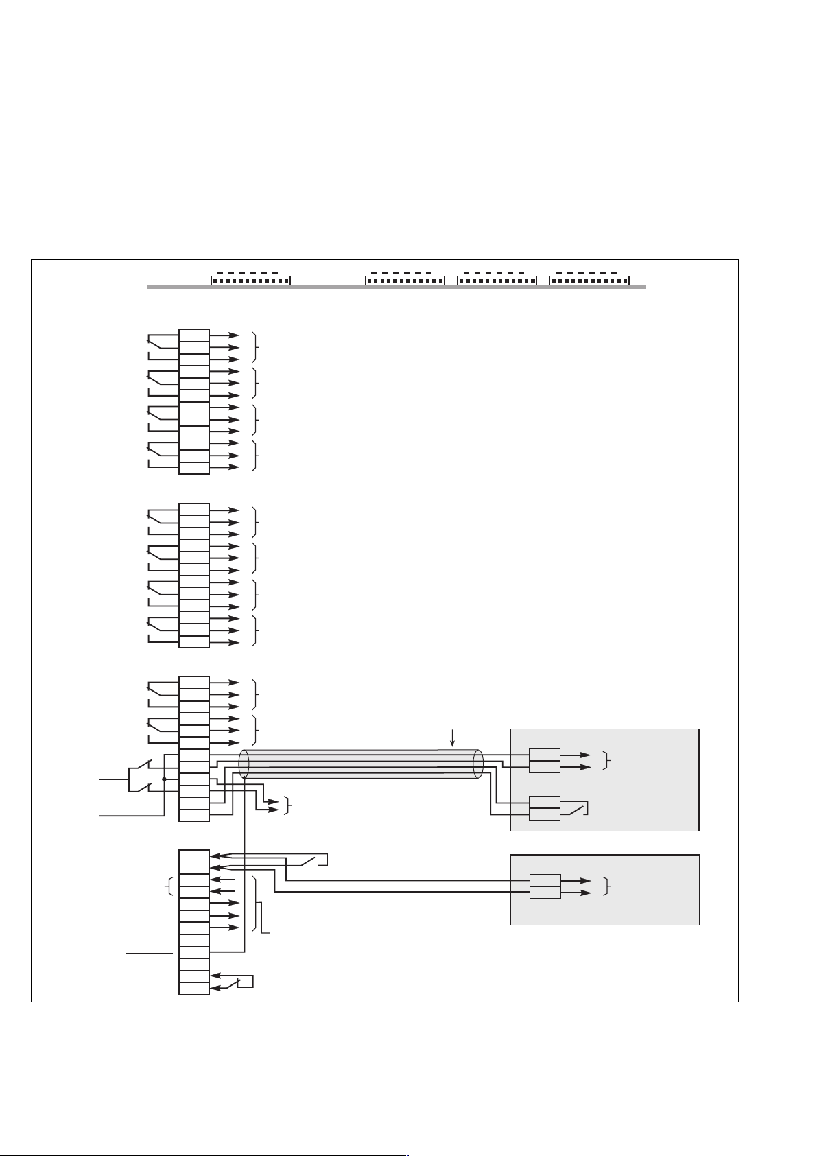
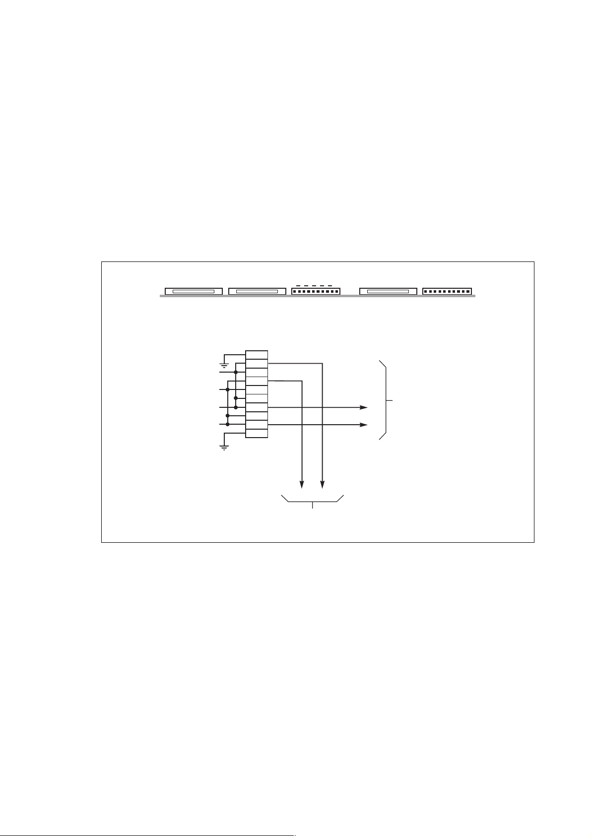
2.8 Connection of "Media Contacts 9" standard auxiliary circuits (figure 16)
The standard auxiliary circuits of the rectifier-inverter and Static Switch Cubicles are connected to the remote relay board by
4 connectors (see the location of this board in the figures of the previous section).
– recommended cable cross-section: 1 mm
– the male connectors that fit the female connectors on the board (XR1 to XR4) are supplied;
– the contacts are volt-free and are shown in the diagram under the following conditions: UPS on, contact at rest;
– contact breaking capacity: 250 V, 5 A.
Connection of auxiliary circuits on the remote relay board
2
(use a shielded cable to connect the battery cell);
remote
relay board
connector XR1
connector XR2
connector XR3
+12V
24 V DC
-
12V
connector XR4
temperature
signal
power
supply
earth
earth
-12V
+12V
1
1
2
3
4
5
6
7
8
9
10
11
12
1
2
3
4
5
6
7
8
9
10
11
12
1
2
3
4
5
6
7
8
9
10
11
12
1
2
3
4
5
6
7
8
9
10
11
12
12
XR1 XR2 XR3
output signals:
low battery shutdown warning (1)
low battery shutdown warning (1)
load on battery (1)
load on battery (1)
output signals:
load on inverter (2)
load on inverter (2)
general alarm (2)
general alarm (2)
input or output signals:
maintenance position (2)
maintenance position (2)
battery circuit breaker
QF1 opening command (1)
input or output signals:
and/or harmonics filter temperature fault
connection with the optional electronic
board for measuring battery temperature (1)
emergency shutdown button contact
(jumper if not used) (1)
1
battery room ventilation fault (1)
12
1
shielded cable
(2 twisted
telephone pairs)
12
1
(1) for:
single-unit UPS cubicle,
modular UPS cubicle,
parallel UPS cubicle with SSC.
(2) for:
single-unit UPS cubicle,
modular UPS cubicle,
parallel UPS cubicle with SSC,
Static Switch cubicle.
battery cubicle (1)
XR1 terminal block
3
4
1
2
harmonics filter cubicle
XR1 terminal block
1
2
12
XR4
battery circuit
breaker QF1
opening command
battery circuit
breaker QF1
closing command
temperature
monitoring of
the harmonics
filter inductor
Fig. 16
34006451EN/AC - Page 22
Page 23
Installation
Connection to battery circuit breaker QF1
Connect the cable from connector XR3 (pins 7 to 12) of the rectifier-inverter cubicle remote relay board to connector XR1 of
the battery cubicle containing battery circuit breaker QF1.
Emergency shutdown
The UPS emergency shutdown function is generally wired to a "mushroom-head" type emergency off button.
Important:
In the case of a complex installation with a number of units, there should only be one emergency shutdown pushbutton and
this pushbutton must interrupt all the active conductors of all the units.
For the same reason, it is essential for the pushbutton to open the upstream mains 1, mains 2, and external maintenance
bypass line protective circuit breakers.
Each type of unit (UPS and Static Switch Cubicle) must have an independent, volt-free contact connected to the emergency
shutdown pushbutton. This pushbutton must therefore have as many contacts as there are units in the installation, as well as
the contact or contacts required to open the upstream mains 1 and 2 protective circuit breakers. The emergency shutdown
pushbutton turns off the rectifier-chargers and inverters and opens the battery circuit breakers. The emergency shutdown
signal will be cleared when the emergency shutdown pushbutton contact has been reset.
The emergency shutdown pushbutton should not be connected to the Static Switch Cubicle since the pushbutton opens the
circuit breaker protecting the upstream circuit (mains 2) and the Static Switch Cubicle is therefore no longer powered (inverters off and mains 2 down).
2.9 Connections between cubicles (modular UPSs or parallel UPSs with SSC)
On modular UPSs, interconnections are made on the APOZ (figure 17) and MISI (figures 19 to 21) boards in the UPS cubicles
(see the layout of the boards in the figures in the previous section).
For parallel UPSs with a centralised SSC, interconnections are made on the APOZ boards in the UPS cubicles (figure 17)
and the ACPZ boards (see the layout of the boards in the figures in the previous section) in the SSC (figure 18).
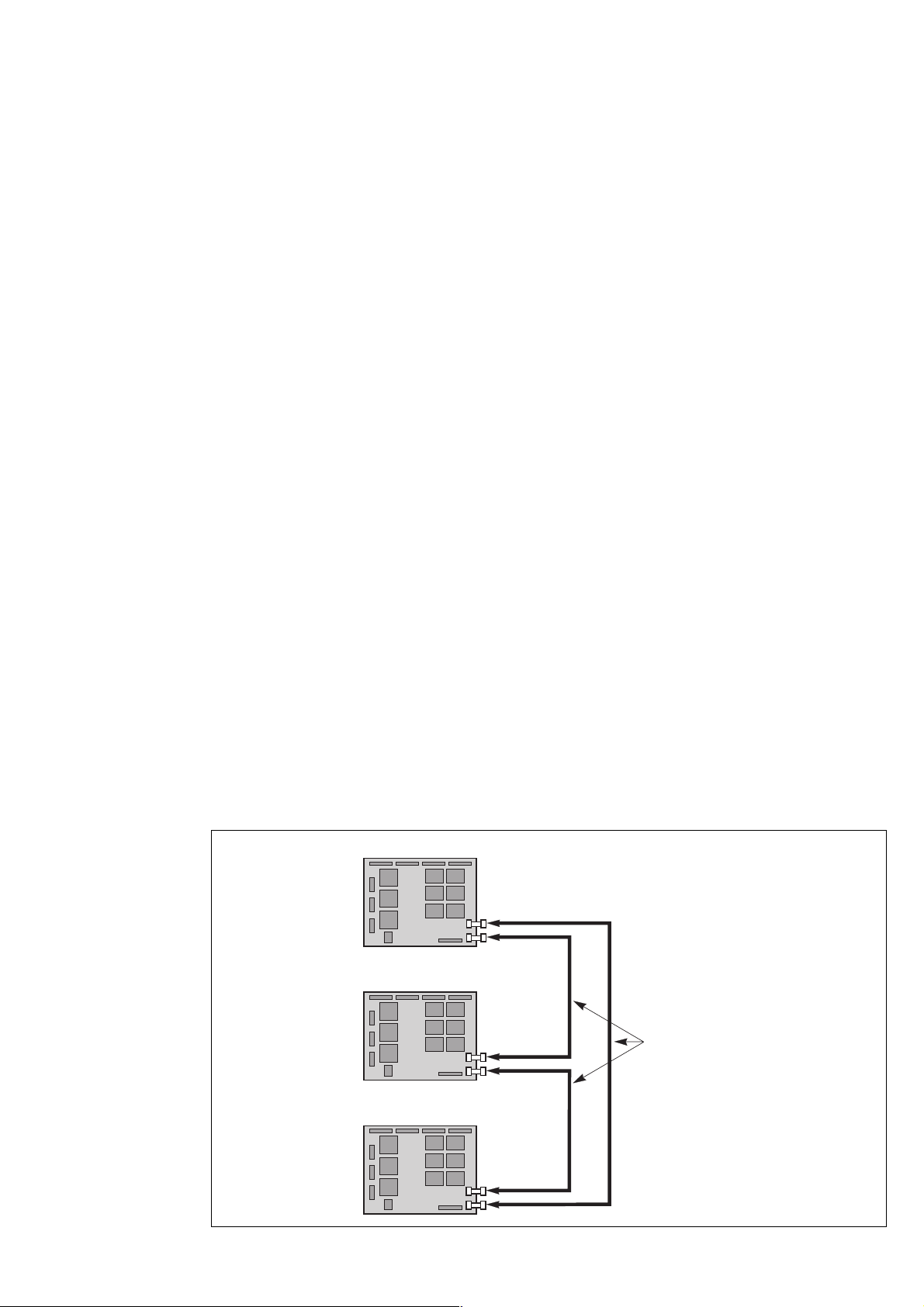
Connections between APOZ boards
– these connections are made using the ribbon cables supplied;
– the purpose of the connection is to make a loop: connector XM137 of the APOZ board of one UPS being connected to
connector XM136 of the APOZ board of the next UPS and so on until the first board is returned to.
Important:
Outside the cubicles, group the APOZ inter-board and ACPZ or MISI inter-board connections with the inter-cubicle auxiliary
connections, and separate this assembly from the power cables.
Connections between rectifier-inverter cubicles
APOZ board
rectifier-inverter 1
XM137
XM136
APOZ board
rectifier-inverter 2
XM137
XM136
ribbon cables supplied
Fig. 17
APOZ board
rectifier-inverter 3
XM137
XM136
34006451EN/AC - Page 23
Page 24

Installation
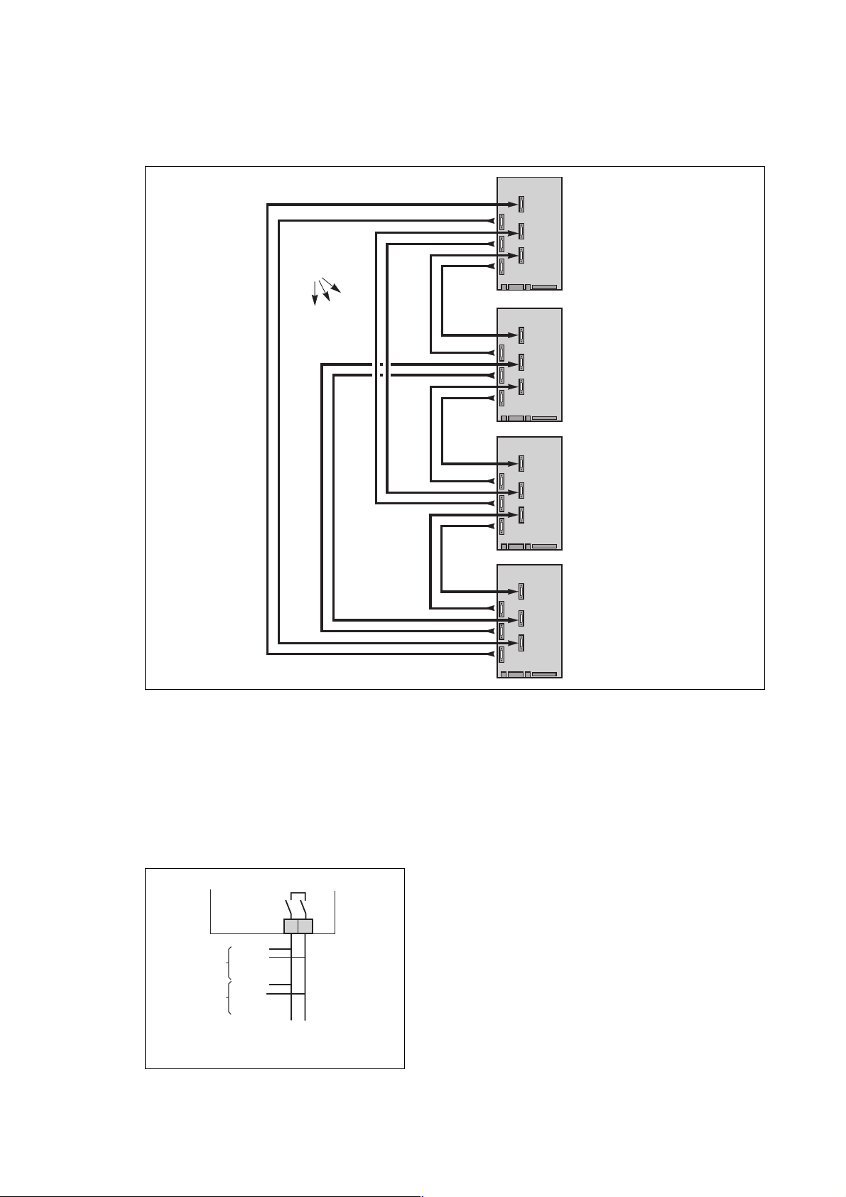
Connections between ACPZ boards (frequency converters or parallel UPSs
with SSC)
– these connections are made through the special cables supplied;
– these connections only concern installations with a Static Switch Cubicle and should be made in addition to the connections
between rectifier-inverter cubicles described previously;
– the ribbon cable from connector XM133 of the ACPZ board of one rectifier-inverter cubicle is connected to one of the
connectors XM127 to XM132 of the ACPZ board of the Static Switch Cubicle.
Important:
Outside the cubicles, group the APOZ inter-board and ACPZ inter-board connections with the inter-cubicle auxiliary
connections, and separate this assembly from the power cables.
Connections between each rectifier-inverter cubicle and the Static Switch Cubicle (example
of 3 parallel UPS rectifier-inverters with SSC)
ACPZ board
rectifier-inverter 3
ribbon cable
supplied
XM133
Fig. 18
ACPZ board
rectifier-inverter 2
ACPZ board
rectifier-inverter 1
XM133
XM133
ribbon cable
supplied
ribbon cable
supplied
ACPZ board
of the static
switch cubicle
XM
127XM128XM129XM130
XM
131XM132
34006451EN/AC - Page 24
Page 25

Installation
Connections between MISI boards (modular UPSs)
See figures 19 to 21.
– these connections are made using the special cables (A) supplied;
– connectors XM5, XM6 and XM7 on the MISI board are used to transmit signals;
– connectors XM10, XM11 and XM12 on the MISI board are used to receive signals;
– connector XM5 is associated with connector XM10 for communication with a second UPS unit; similarly, XM6 is associated
with connector XM11 for communication with a third UPS unit and XM7 is associated with connector XM12 for communication
with a forth UPS unit;
– situation with two modular UPS units: see figure 19;
– situation with three modular UPS units: see figure 20;
– situation with four modular UPS units: see figure 21.
Fig. 19
MISI
board
UPS 1
XM12
XM7
XM6
XM5
A
XM7
XM6
XM5
XM11
XM10
XM12
XM11
XM10
MISI
board
UPS 2
A
XM7
XM6
XM5
XM7
XM6
XM5
XM7
XM6
XM5
XM12
XM11
XM10
XM12
XM11
XM10
XM12
XM11
XM10
MISI
board
UPS 1
MISI
board
UPS 2
MISI
board
UPS 3
Fig. 20
34006451EN/AC - Page 25
Page 26
Installation
Important
Outside the cubicles, group the cables between the MISI boards and those between the APOZ boards with the other auxiliary
links between cubicles and separate all these cables from the power cables.
MISI
board
XM12
XM7
XM6
A
XM5
XM7
XM6
XM5
XM7
XM6
XM5
XM11
XM10
XM12
XM11
XM10
XM12
XM11
XM10
UPS 1
MISI
board
UPS 2
MISI
board
UPS 3
MISI
board
UPS 4
XM7
XM6
XM5
XM12
XM11
XM10
Fig. 21
2.10 Connections between rectifier-inverter cubicles and external maintenance
bypass cubicle
– make connections with 1 mm
– connect terminals 1 and 2 on connector XM8 on the MISI board in the UPS to terminals 1 and 2 in the external
maintenance bypass.
maintenance
bypass
cubicle
Q3BP +
MISI 1
MISI 2
Q3BP -
Q3BP +
Q3BP -
2
wires (recommended size, not supplied);
Q3BP12Q5N
1
XM8
2
1
XM8
2
34006451EN/AC - Page 26
MISI 3
MISI 4
Page 27

2.11 Connection of "Media Contacts 15" additional auxiliary circuits
(figure 22)
The additional auxiliary circuits of the rectifier-inverter and Static Switch Cubicles are connected to additional remote relay
board by means of the 4 connectors (see location of this board in the figures of the "connection of power circuits" section).
– recommended cable cross-section: 1 mm
– the male connectors that fit the female connectors on the board (XR5 to XR9) are supplied;
– the contacts are volt-free and are shown in the diagram under the following conditions: UPS on, contact at rest;
– contact breaking capacity: 250 V, 5 A.
Note:
In a parallel-connected UPS installation the "load" and "mains 2" signals are provided by the Static Switch Cubicle.
ACPZ board of the Static Switch Cubicle
2
;
Installation
additional remote
relay board
connector XR5
(option)
connector XR6
(option)
connector XR7
(option)
connector XR8
(option)
connector XR9
(option)
12
XR7
UPS cubicle,
UPS cubicle,
UPS cubicle,
UPS cubicle,
XR8
10
1
overload (2)
overload (2)
inverter function fault (1)
inverter function fault (1)
rectifier-charger operating (1)
rectifier-charger operating (1)
rectifier-charger function fault (1)
rectifier-charger function fault (1)
transfer to Mains 2 inhibited (3)
transfer to Mains 2 inhibited (3)
transfer function fault (2)
transfer function fault (2)
transfer to Mains 2 inhibited (4) (5)
transfer to Mains 2 with interruption inhibited (4) (5)
desynchronization with Mains 2 (3)
battery charge current limiting (1)
gradual rectifier-charger shutdown (1)
current limiting on generator power (1)
remote inverter on (1)
remote inverter off (1)
auxiliary signal (2)
1
1
2
3
4
5
6
7
8
9
10
11
12
1
2
3
4
5
6
7
8
9
10
11
12
1
2
3
4
5
6
7
8
9
10
11
12
1
2
3
4
5
6
7
8
9
10
1
2
3
4
5
6
7
8
XR9
10
1
XR5
12
1
output signals:
XR6
input signals:
12
1
(1) for:
single-unit
modular UPS cubicle,
parallel UPS cubicle with SSC.
(2) for:
single-unit
modular UPS cubicle,
parallel UPS cubicle with SSC,
Static Switch cubicle.
(3) for:
single-unit
modular UPS cubicle,
Static Switch cubicle.
(4) in modular UPSs, these functions are
available via the "auxiliary information" contact
(connector XR9, terminals 7-8).
(5) for:
single-unit
static Switch cubicle.
Fig. 22
34006451EN/AC - Page 27
Page 28
Installation
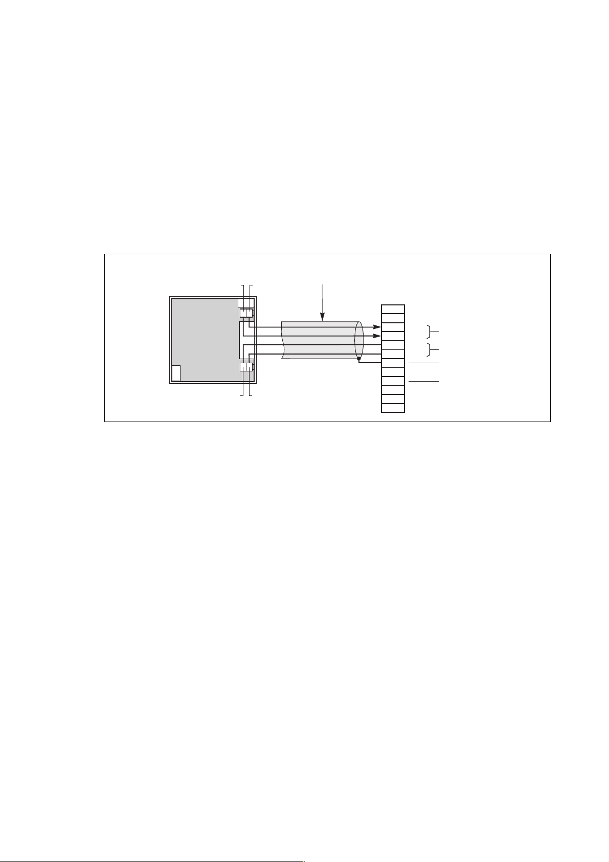
2.12 Connection of the battery "Temperature Monitor" (optional)
Connections
This unit must be connected to connector XR4 of the remote relay board of the rectifier-inverter cubicles (see the location of
the remote relay board in the figures of the "power circuit connection" section).
– use a shielded cable made up of 2 twisted telephone pairs with a conductor cross-section of at least
–0.1 mm
– do not forget to connect the cable shield to ground pin 7 of connector XR4;
– in the case of a parallel UPS configuration, the connections between cubicles may be made by means of a shielded cable
made up of 1 or 2 twisted telephone pairs. In this case, the total length of all the connecting cables should not exceed 100 m;
– a "Temperature Monitor" can only be connected to several rectifier-inverter cubicles when the batteries of these cubicles
are located in the same room at the same ambient temperature.
Connection of the battery "Temperature Monitor" (for a single-unit UPS)
2
and up to 100 m in length;
Fig. 23
battery "Temperature
Monitor"
BC+ BC
XR2
XR1
12 +12
(unit shown open)
shielded cable
(2 twisted
telephone pairs)
remote relay board
connector XR4:
1
2
3
BC
BC +
4
5
12V
6
+
12V
7
8
9
10
11
12
temperature
signal
power supply
earth
earth
34006451EN/AC - Page 28
Page 29

Installation
Connection of the battery "Temperature Monitor" (for a parallel UPS with batteries in the same room)
battery "Temperature
Monitor"
BC+ BC
XR2
XR1
12 +12
(unit shown open)
shielded cable
(2 twisted
telephone pairs)
shielded cable
(1 or 2 twisted
telephone pairs)
remote relay board
connector XR4 on
rectifier-inverter cubicle 1:
1
2
3
BC
BC +
4
5
+
6
7
8
NC
9
10
11
12
remote relay board
connector XR4 on next
rectifier-inverter cubicle:
3
4
5
6
7
8
NC
remote relay board
connector XR4 on nth
rectifier-inverter cubicle:
1
2
3
BC
4
BC +
5
6
7
8
9
10
11
12
12V
12V
BC
BC +
temperature
signal
power supply
earth
earth
temperature
signal
earth
temperature
signal
earth
earth
Fig. 24
"Temperature Monitor" installation in a battery room
The "Temperature Monitor" should be secured against a wall or any vertical support:
– choose a location near the batteries and away from draughts which adversely affect the accuracy of temperature
measurements;
– position the unit correctly ("on" light in the top left hand corner and cable fed through from the right-hand side);
– use the holes provided in the base plate to screw the unit to the vertical support (see figure 25);
– unless the connecting cable runs on the surface, break the knock-out in the unit base plate provided for cable entry;
– secure the cable by suitable means so that it does not pull on the unit.
"Temperature Monitor" base
oblong holes
for fastening screws
board
oblong holes
for fastening screws
dimensions of the "Temperature Monitor": 75 x 75 x 21 mm
knock-out for
lateral cable
entry
Fig. 25
34006451EN/AC - Page 29
Page 30
Installation
2.13 Connection of the "LED" remote indications unit
This unit is connected to connectors XR1 and XR2 of the remote relay boards of the rectifier-inverter and Static Switch
Cubicles (see the location of these boards in the figures of the "connection of power circuits" section).
For the installation of the unit and details of connections at the unit end, see the instructions delivered with the unit
nr 5102990400.
– recommended cable cross-section: 1 mm
2
.
2.14 Connection of "Tele Monitor" remote control and indication unit
This unit is connected by means of a signal loop connecting the XR10 connectors of the RAUZ 1 boards of the rectifier-inverter
and Static Switch Cubicles to the unit connectors. These RAUZ 1 boards are located near the remote relay boards.
– recommended cable cross-section: shielded 0.4 mm
– consult manual 6739388XU for further information.
Connection of "Tele Monitor" remote control and indication unit
RAUZ 1 board
XM098
connector XR10
reception
reception
+
transmission
transmission
+
XM097 XM096
1
2
3
4
5
6
7
8
9
10
2
cables;
1
XR11
10
XR10
to connector XR081
on the COMZ board
2
in the "Tele Monitor" unit
4
(option)
Fig. 26
2.15 Final installation steps
After making the connections:
– install the front and rear base plates of the cubicles, clipping them to the feet of the cubicles (unless the connecting cables
are fed through these openings);
– refit the terminal shields of the terminal blocks, switches and circuit breakers.
97
to connector XR10
of another rectifier-inverter
or static switch cubicle
34006451EN/AC - Page 30
Page 31

3.1 Mains 2 line protection
The rating of the mains 2 line upstream protection circuit-breaker must be chosen:
– to protect the static switch thyristors with respect to maximum permissible currents. Refer to the table opposite for a 400 V
mains 2 voltage;
– to ensure discrimination with respect to the UPS output fuses (refer to fuse time-current curves below) and to the
downstream protective devices.
rated inverter output (kVA) maximum permissible current
800 19 In for 20 ms
900 19 In for 20 ms
3. Appendix (to be carried out by qualified personnel only)
t(s)
4
10
3
10
2
10
1
10
1
-1
10
-2
10
-3
10
-4
10
3
10
4
10
5
10
I(A)
Time-current curve 1600 A fuse
34006451EN/AC - Page 31
Page 32

Appendix
3.2 Cubicle mounting and connection for 2000 kVA Static Switch Cubicle
Cubicle mounting
– move the cubicles to their operating location;
– adjust the front foot pads so that the cubicles are vertical and their doors aligned.
Internal connections between cubicles
– install and bolt the supplied fish-plates on the bars for the phases and neutral (L1, L2, L3, N) between the two cubicles
(four bars in top and four bars in bottom);
– connect the earth strap to the front uprights of both cubicles;
– connect the connectors marked XM1 and XM2 from the left cubicle to the connectors marked XF1 and XF2
in the right cubicle.
left cubicle right cubicle
K2S
L3
L1
N
L2
XF1-XF2
XM1-XM2
L1 L2 L3N
card cage
off
off
off
Q4S
on
Q3BP
Q5N
on
on
L2
L3
L1
N
34006451EN/AC - Page 32
earth strap to be connected
to the front uprights of both
cubicles
spacing
uprights
Page 33

Right cubicle of a 2000 kVA Static Switch
cross-section AA front view
air extraction
front
air
admission
rear
Appendix
A
on
off
Q4S
L2
L3
on
off
Q3BP
L1
N
air
admission
mains 2
on
off
Q5N
connection
from below
trough (if applicable)
spacing uprights
power cable routing via the bottom
Cables connected by lugs to 5 x (5 x 100) mm copper terminals and 16 mm diameter holes.
Height of connections relative to floor:
– mains 2 : 1400 mm;
– load: 800 mm.
load
L2
L3
A
L1
N
34006451EN/AC - Page 33
Page 34
Appendix
Left cubicle of a 2000 kVA Static Switch
cross-section AA front view
air extraction
front
air
admission
rear
A
K2S switch
ACPZ board
XM127 to 132
air
admission
card cage
connection
from below
trough (if applicable)
L1 L2 L3N
inverter outputs
spacing
uprights
power cable routing via the bottom
Cables connected by lugs to 5 x (5 x 100) mm copper terminals and 16 mm diameter holes.
Height of connections relative to floor:
– inverter outputs : 700 mm
– remote relay board: 500 mm.
XR7
XR6
XR5
XR9
XR8
remote
relay
board
XR4
XR3
XR2
remote
XR1
relay
board
A
34006451EN/AC - Page 34
Page 35

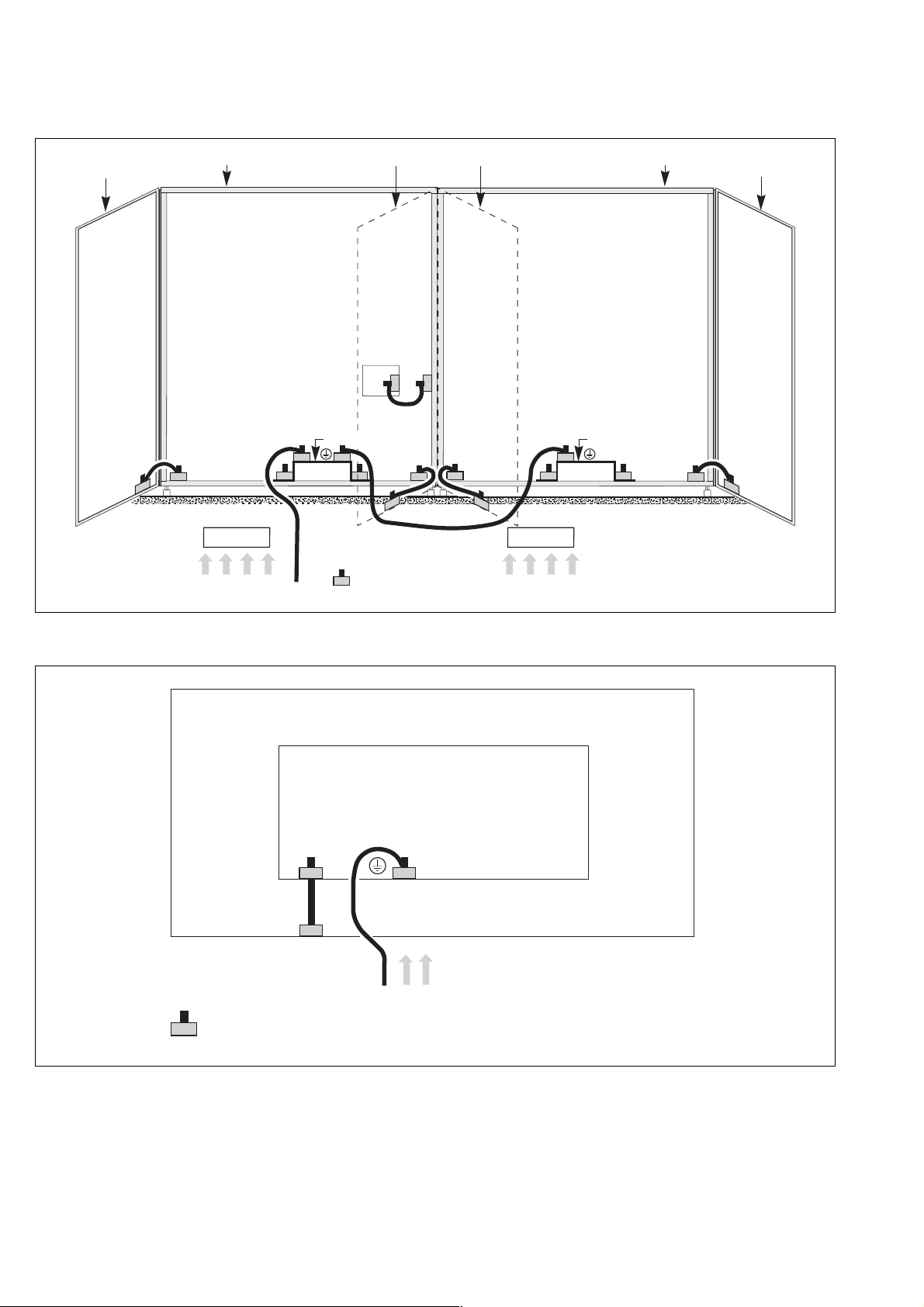
3.3 Details of earthing connections in the various cubicles
Rectifier-inverter cubicle
Appendix
door
three-phase
inductor
frame
left cubicle right cubicle
battery
inductor
inverter
transformer
inverter
input
mains 1
door
transformer
AIRZ AIRZ
door
inverter
input
connection with
a bolt, nut and
contact washer
mains 2
inverter
transformer
earth bar
frame
transformer
door
door
120 to 1200 kVA Static Switch Cubicles
frame
earth bar
transformer
AIRZ
AIRZ
only for 120
to 800kVA
static-switch
cubicles
door
connection with a bolt,
nut and contact washer
mains 2
input
inverters
34006451EN/AC - Page 35
Page 36
Appendix
2000 kVA Static Switch Cubicles
door
input
inverters
door
SYNI
earth bar earth bar
input
connection with
a bolt, nut and
contact washer
mains 2
framedoorframe
door
"Tele-Monitor" unit
connection with a bolt,
nut and contact washer
Tele Monitor unit
COMZ
mains
34006451EN/AC - Page 36
Page 37

34006451EN/AC - Page 37
Page 38

34006451EN/AC - Page 38
Page 39

34006451EN/AC - Page 39
Page 40

34006451EN/AC
 Loading...