

Page 1
SingleandParallel
Installation
MGE™Galaxy™3500
10-30kVA208/220V
Page 2

AmericanPowerConversionLegalDisclaimer
TheinformationpresentedinthismanualisnotwarrantedbytheAmericanPowerConversion
Corporationtobeauthoriative,errorfree,orcomplete.Thispublicationisnotmeanttobe
asubstitutefordetailedoperationalandsitespecicdevelopmentplan.Therefore,American
PowerConversionCorporationassumesnoliabilityfordamages,violationsofcodes,improper
installation,systemfailures,oranyotherproblemsthatcouldarisebasedontheuseofthis
Publication.
TheinformationcontainedinthisPublicationisprovidedasisandhasbeenpreparedsolely
forthepurposeofevaluatingdatacenterdesignandconstruction.ThisPublicationhasbeen
compiledingoodfaithbyAmericanPowerConversionCorporation.However,nopresentation
ismadeorwarranty ,eitherexpressorimplied,astothecompletenessoraccuracyofthe
informationthisPublicationcontains.
NOEVENTSHALLAMERICANPOWERCONVERSIONCORPORA TIONBELIABLE
FORANYDIRECT,INDIRECT,CONSEQUENTIAL,PUNITIVE,SPECIAL,OR
INCIDENTALDAMAGES(INCLUDING,WITHOUTLIMITA TION,DAMAGESFOR
LOSSOFBUSINESS,CONTRACT ,REVENUE,DA TA,INFORMA TION,ORBUSINESS
INTERRUPTION)RESULTINGFROM,ARISINGOUT ,ORINCONNECTIONWITHTHE
USEOF ,ORINABILITYTOUSETHISPUBLICA TIONORTHECONTENT,EVENIF
AMERICANPOWERCONVERSIONCORPORA TIONHASBEENEXPRESSL YADVISED
OFTHEPOSSIBILITYOFSUCHDAMAGES.AMERICANPOWERCONVERSION
CORPORATIONRESERVESTHERIGHTTOMAKECHANGESORUPDA TESWITH
RESPECTTOORINTHECONTENTOFTHEPUBLICATIONORTHEFORMAT
THEREOFA TANYTIMEWITHOUTNOTICE.
Copyright,intellectual,andallotherproprietaryrightsinthecontent(includingbutnotlimited
tosoftware,audio,video,text,andphotographs)restswithAmericanPowerConversion
Corporationoritslicensors.Allrightsinthecontentnotexpresslygrantedhereinarereserved.
Norightsofanykindarelicensedorassignedorshallotherwisepasstopersonsaccessing
thisinformation.
ThisPublicationshallnotbeforresaleinwholeorinpart.
Page 3

TableofContents
IMPORTANTSAFETYINSTRUCTIONS–SAVETHESE
INSTRUCTIONS...............................................................................................................1
Specications...................................................................................................................2
ACInputSpecications..............................................................................................2
ACBypassInputSpecications..............................................................................2
ACOutputSpecications..........................................................................................3
BatterySpecications................................................................................................3
RecommendedCableSizes......................................................................................4
ConnectionTerminals................................................................................................4
TorqueSpecications................................................................................................4
FusesandBreakers....................................................................................................5
SingleUtility/MainsSystem.......................................................................................5
DualUtility/MainsSystem..........................................................................................5
ParallelSystem..........................................................................................................6
FuseandBreakerSizesinSingleSystems................................................................6
FuseandBreakerSizesinParallelSystems..............................................................6
MinimumBreakerSettings........................................................................................7
MechanicalInstallation...............................................................................................8
Clearance.......................................................................................................................8
LeveltheCabinet.........................................................................................................8
RemovetheFrontPanel............................................................................................9
FloorAnchoring..........................................................................................................9
HolePositionsforaStand-aloneUPSEnclosurewithL-shapedAnchoring
Brackets....................................................................................................................10
HolePositionsforUptoFourUPSUnitsinParallelwithU-shapedAnchoring
Brackets...................................................................................................................10
ConnectFloorAnchoringBracketstotheUPSandXRBatteryEnclosurefor
Stability......................................................................................................................11
RemovetheBatteryModules.....................................................................................12
InstalltheBayingKit(Optional)forInterconnectionofEnclosuresandSeismic
Anchoring..................................................................................................................13
InstallXRBatteryEnclosures(Option)..............................................................16
RemovetheCableLandingCoverandBottomPlates......................................16
ConnectBatteryPowerinInstallationswithBusbars.......................................17
IsolatorInstallationPrinciple.....................................................................................17
990-1957C-001
MGE™Galaxy™350010-30kV A208/220VSingleandParallelInstallation
i
Page 4

InstallBusbarsin523mm(20.59in)UPSSystemwiththeUPSPlacedtotheLeft
(seenfromthefront)..................................................................................................18
InstallBusbarsin523mm(20.59in)UPSSystemwiththeUPSPlacedtothe
Right(seenfromthefront)........................................................................................19
InstallBusbarsin352mm(13.85in)UPSSystemwiththeUPSPlacedtothe
Right(seenfromthefront)........................................................................................20
InstallBusbarsin352mm(13.85in)UPSSystemwiththeUPSPlacedtotheLeft
(seenfromthefront)..................................................................................................21
ConnectBatteryPowerinInstallationswithCables..........................................22
ConnectPowerCablesBetweentheUPSandtheXRBatteryEnclosure..................22
ConnectPowerCablesbetweenTwoXRBatteryEnclosures....................................23
ConnectthePowerCablestotheUPS...............................................................25
SingleSystem10-30kVA208V................................................................................25
SingleSystem10-30kVA480V................................................................................26
PrepareforCables.......................................................................................................27
BottomCableEntry...................................................................................................27
ConnecttheACInputandACOutputCables......................................................28
SingleMains..............................................................................................................28
DualMains.................................................................................................................28
ConnecttheDCBatteryCables(ifapplicable)...........................................................29
ConnecttheCommunicationCables..................................................................30
PrepareforCommunicationCables........................................................................30
OverviewofPinConnections...................................................................................31
J106...........................................................................................................................31
EPOinSingleSystems...............................................................................................32
EPOinParallelSystems............................................................................................33
ConnectCommunicationCablesbetweenUPSandXRBattery
Enclosure.......................................................................................................................34
ConnectAPCCommunicationOptions.................................................................35
ConnectCommunicationCablesinParallelSystem..........................................36
OverviewofthePBusCables....................................................................................36
PrepareforCables.....................................................................................................37
UPSUnitsApartwithoutConduitsandInterconnection..................................38
UPSUnitsBayedTogetherwithoutConduits......................................................39
UPSUnitsApartorBayedTogetherwithConduits...........................................40
InstallSeismicOption..................................................................................................42
InstalltheSeismicBatteryLock..............................................................................42
ii
MGE™Galaxy™350010-30kV A208/220VSingleandParallelInstallation
990-1957C-001
Page 5

InstalltheSeismicStabilizingBrackets................................................................42
FinalMechanicalInstallation...................................................................................44
ConnectBatterySecuringBracketsforStability................................................44
ReinstalltheT opCoverandtheFrontPanel.......................................................45
990-1957C-001
MGE™Galaxy™350010-30kV A208/220VSingleandParallelInstallation
iii
Page 6

iv
MGE™Galaxy™350010-30kV A208/220VSingleandParallelInstallation
990-1957C-001
Page 7

IMPORTANTSAFETYINSTRUCTIONS– SAVETHESEINSTRUCTIONS
WARNING:ALLsafetyinstructionsintheSafetySheet(990-2940)mustberead,
understood,andfollowedwheninstallingtheUPSsystem.Failuretodosocouldresult
inequipmentdamage,seriousinjury,ordeath.
WARNING:AftertheUPShasbeenelectricallywired,donotstartitup.Start-upis
commissionedtoauthorizedpersonnelfromSchneiderElectric.
WARNING:WhentheUPSinputisconnectedthroughexternalisolatorsthat,when
opened,isolatetheneutral,orisconnectedtoanITpowerdistributionsystem,alabel
mustbettedattheUPSinputterminalsbytheUPSsupplier ,andonallprimary
powerisolatorsinstalledremotefromtheUPSareaandonexternalaccesspoints
betweensuchisolatorsandtheUPSbytheuser,displayingthefollowingtext(or
equivalent):"Riskofvoltagebackfeed.Beforeworkingonthiscircuit,isolatetheUPS
andcheckforhazardousvoltagebetweenallterminalsincludingtheprotectiveearth."
Caution:Allelectricalpowerandpowercontrolwiringmustbeinstalledbyaqualied
electricianandmustcomplywithlocalandnationalregulationsformaximumpowerrating.
Caution:Waituntilthesystemisreadybepoweredupbeforeinstallingbatteries.Failure
todosocanresultinadeepdischargeofthebatteriesandcausepermanentdamage(the
timefromthebatteryinstallationtimetilltheUPSispoweredupshouldnotexceed72
hoursor3days.
Note:ThesystemisdesignedforconnectiontoanITpowerdistributionsystem.
Note:Theparallelcablesmustberunbytheelectricianbutnotattached.Theeldservice
engineerfromSchneiderElectricwillinstalltheparallelcommunicationboxandattachall
cablestotheUPSunits.
Note:UptofourUPSunitscanruninparallel.
Note:EnsurethattheallUPSunitsareintheirnallocationpriortotheinstallation.
Note:Batteryandutility/mainspowermustnotbeconnecteduntilallotherwiringhas
beencompleted.
990-1957C-001
MGE™Galaxy™350010-30kV A208/220VSingleandParallelInstallation
1
Page 8

Specications
WARNING:TheUPSmustbesuppliedfroma208/120Vor220/127V4W+GND
60HZsource.
ACInputSpecications
10kV A15kV A20kV A30kV A
208V220V208V220V208V220V208V220V
Connectiontype4-wire(3PH+N+G)
Inputfrequency
(Hz)
Ithd<5%atfullload
Nominputcurrent
(A)
Maxinputcurrent
(A)
Inputcurrent
limitation(A)
Inputpowerfactor
correction
MaximumShort
CircuitWithstand
(kA)
40-70
24.323.036.634.648.645.873.269.0
26.725.240.238.053.050.180.175.8
32.832.849.549.565.265.298.898.8
>0.98atload>50%
30
ACBypassInputSpecications
10kV A15kV A20kV A30kV A
208V220V208V220V208V220V208V220V
Connectiontype4-wire(3PH+N+G)
Inputfrequency
(Hz)
Nominputcurrent
(A)
50+/-10or60+/-10
27.826.241.639.4
55.5
52.583.378.7
2
MGE™Galaxy™350010-30kV A208/220VSingleandParallelInstallation
990-1957C-001
Page 9

ACOutputSpecications
10kV A15kV A20kV A30kV A
208V220V208V220V208V220V208V220V
Connectiontype4-wire(3PH+N+G)
Overloadcapacity150%for1minute(normaloperation)
125%for10minutes(normaloperation)
150%for1minute(batteryoperation)
125%for10minutes(batteryoperation)
110%continuous(bypassoperation)
800%for500ms(bypassoperation)
V oltagetolerance160-240Vfor208Vsystems
160-253Vfor220Vsystems
Nomoutput
current(A)
Outputfrequency
(synctomains)
Slewrate(Hz/Sec)
TotalHarmonic
Distortion(THD)
Loadpowerfactor0.5leadingto0.5lagging
Dynamicload
response
Outputvoltage
regulation
27.826.241.639.4
50Hz±0.1Hz,±3Hz,±10Hz
60Hz±0.1Hz,±3Hz,±10Hz
0.25-1
<1.5%linear
<3.5%non-linear
±5%
±1%
55.5
52.583.378.7
BatterySpecications
Type
Nominalvoltage(VDC)+/-192
Floatvoltage(VDC)+/-219
Endofdischargevoltage(VDC)+/-154
Batterycurrent(atfullload)66.5Aat+/-192V
Max.current(atendofdischarge)
Max.chargingpower10kV A:1600W
Typicalre-chargetime5hours
Endvoltage1.6-1.75V/cell(automatic,dependingonload)
VRLA
83.2Aat+154V
15kV A:2400W
20kV A:3200W
30kV A:3200W
990-1957C-001
MGE™Galaxy™350010-30kV A208/220VSingleandParallelInstallation
3
Page 10
RecommendedCableSizes
WARNING:At100%switchmodeload,theneutralmustberatedfor200%phase
current.
Caution:Allwiringmustcomplywithallapplicablenationaland/orelectricalcode.
Note:Therecommendedcablesizesarebasedonanenvironmentwithanambient
temperatureof30°C(86°F).Usestrandedcoppercables.
10kV A15kV A20kV A30kV A
Utility/mainsinput
Staticbypassinput
DCinput
Output8AWG6AWG4AWG1AWG
8AWG6AWG4AWG1AWG
8AWG6AWG4AWG1AWG
1AWG1AWG1AWG1AWG
ConnectionTerminals
Cablesize(A WG)CablelugtypeCrimpingtoolDieTerminalbolt
diameter
12YA12CL2TC38MD7-34RW12CVT
8YA8CL2TC38MD7-34RW8CVT
6YA6CL2TC38MD7-34RW6CVT
4YA4CL2TC38MD7-34RW4CVT
1YA1CL2TC38MD7-34RW1CVT
6mm(0.2in)
6mm(0.2in)
6mm(0.2in)
6mm(0.2in)
6mm(0.2in)
TorqueSpecications
Thepowerwiringshouldbetorquedto7Nm(45lbf-in).
4
MGE™Galaxy™350010-30kV A208/220VSingleandParallelInstallation
990-1957C-001
Page 11

FusesandBreakers
SingleUtility/MainsSystem
•Q1:Utility/mainsinput
•Q2:UPSoutput
•Q3:Manualbypass
•MBS:Mechanicalbypassswitch
DualUtility/MainsSystem
•Q1:Utility/mainsinput
•Q2:UPSoutput
•Q3:Manualbypass
•Q5:Staticbypassinput
•MBS:Mechanicalbypassswitch
990-1957C-001
MGE™Galaxy™350010-30kV A208/220VSingleandParallelInstallation
5
Page 12

ParallelSystem
•Q1:Utility/mainsinput
•Q2:UPSoutput
•Q3:Manualbypass
•Q4:Systemoutput
•Q5:Staticbypassinput
FuseandBreakerSizesinSingleSystems
10kV A15kV A20kV A30kV A
UtilityinputQ1
Staticbypassinput
Q5
UPSoutputQ235A60A80A110A
ManualbypassQ3
35A60A80A110A
35A60A80A110A
35A60A80A110A
FuseandBreakerSizesinParallelSystems
Q3andQ4inParallelCapacitySystems
Unitsinparallel10kV A15kV A20kV A30kV A
270A110A150A225A
3110A175A225A350A
4150A225A300A450A
Q3andQ4inRedundantParallelSystems(n+1)
Unitsinparallel10kV A15kV A20kV A30kV A
235A60A80A110A
370A110A150A225A
4110A175A225A350A
6
MGE™Galaxy™350010-30kV A208/220VSingleandParallelInstallation
990-1957C-001
Page 13

MinimumBreakerSettings
800%overload
bypass
operation
Duration500ms60s10min
1
10kV A
Mainsinput
Staticbypass
-
223A
input
UPSoutput223A42A35A31A
1
15kV A
Mainsinput
Staticbypass
-
333A
input
UPSoutput333A63A52A46A
1
20kV A
Mainsinput
Staticbypass
-
444A
input
UPSoutput444A84A70A62A
1
30kV A
Mainsinput
Staticbypass
-
667A
input
UPSoutput667A125A105A92A
1
Forsinglemainssystems,usethehighervalueofmainsandstaticbypass
150%overload
normal/battery
operation
--
--
--
--
--
--
--
--
125%overload
Continuously
normal/battery
operation
34A
31A
51A
46A
68A
62A
99A
92A
990-1957C-001
MGE™Galaxy™350010-30kV A208/220VSingleandParallelInstallation
7
Page 14
MechanicalInstallation
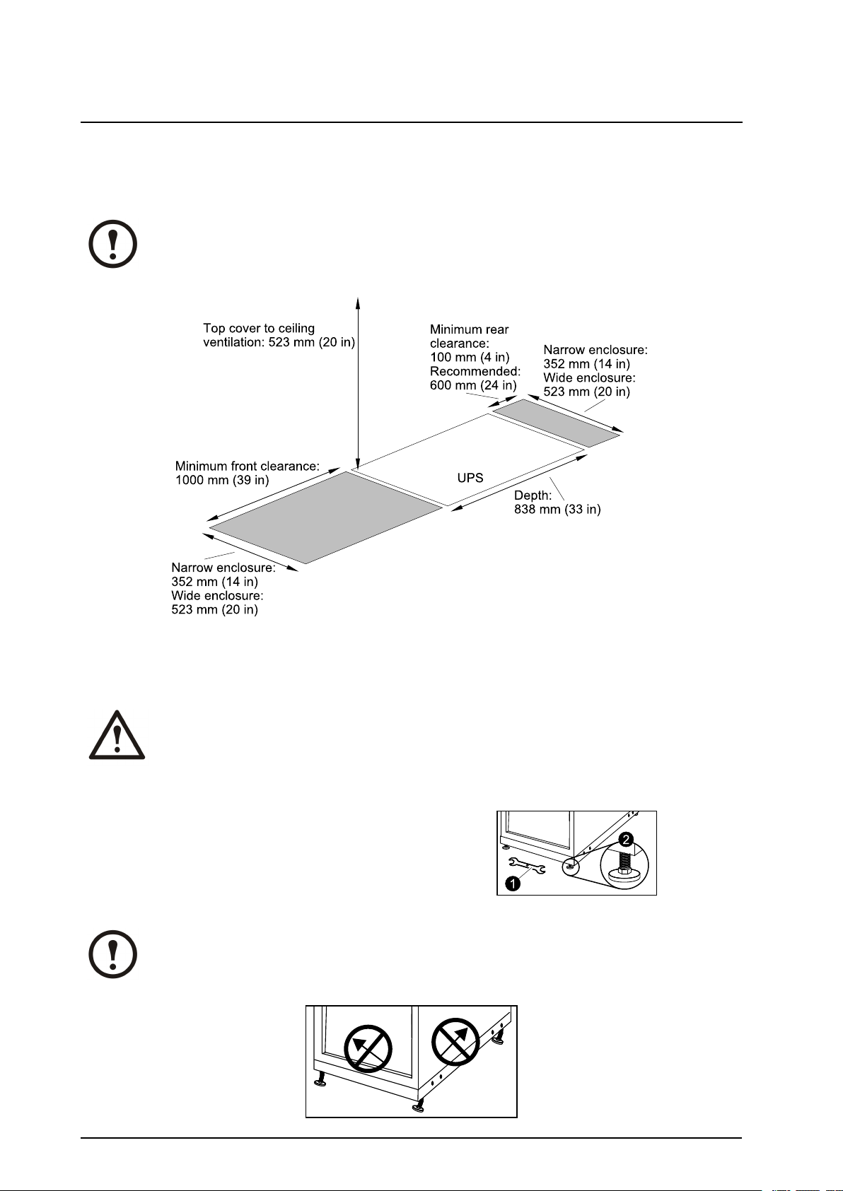
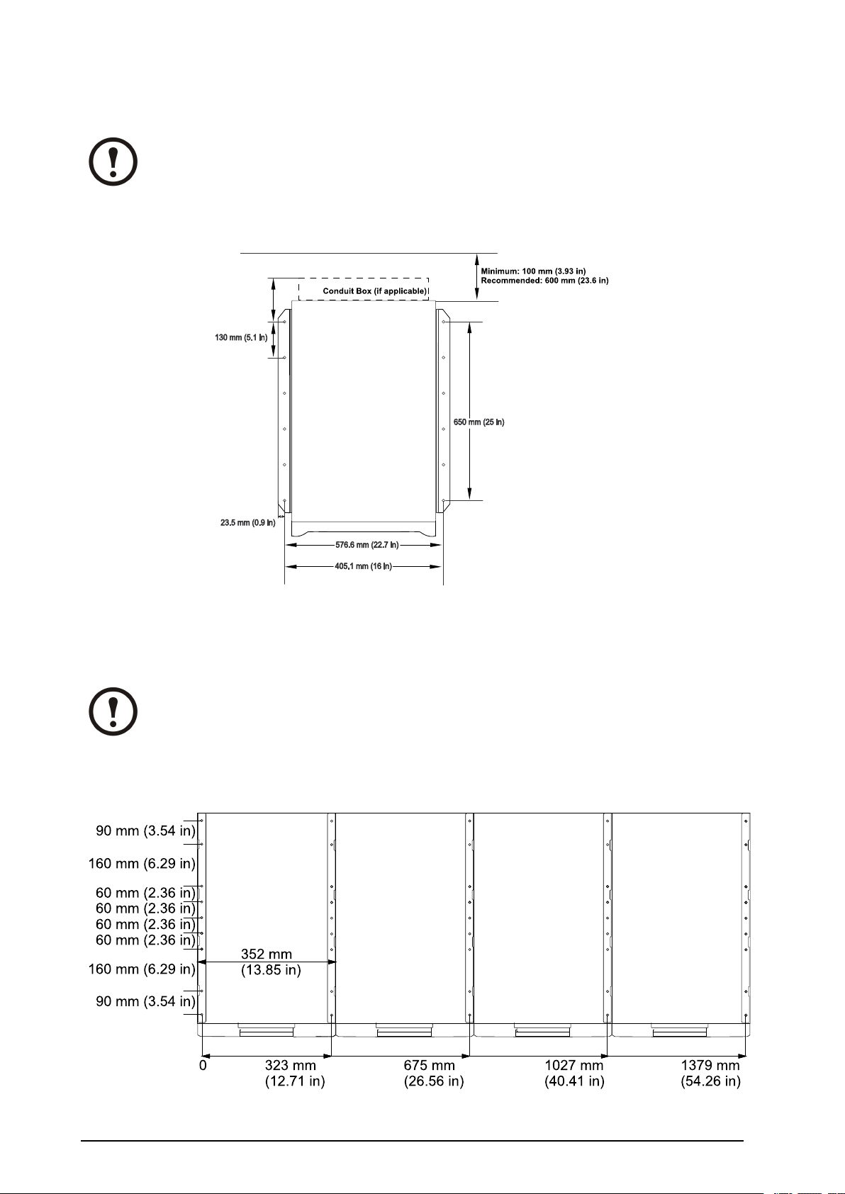
Clearance
Note:Clearancedimensionsarepublishedforairowandserviceaccessonly .Consultwith
thelocalsafetycodesandstandardsforadditionalrequirementsinyourlocalarea.
LeveltheCabinet
WARNING:Thesystemmustbeinstalledonaleveloor .Thelevelingfeetwillstabilize
thecabinet,butwillnotaccountforabadlyslopedoor .
1.Takethe13/14mmwrenchattachedtothe
pallet.
2.Adjustthefourlevelingfeetandensurethat
thesystemislevel.
Note:Donotmovethecabinetafterthelevelingfeethavebeenlowered.
8
MGE™Galaxy™350010-30kV A208/220VSingleandParallelInstallation
990-1957C-001
Page 15
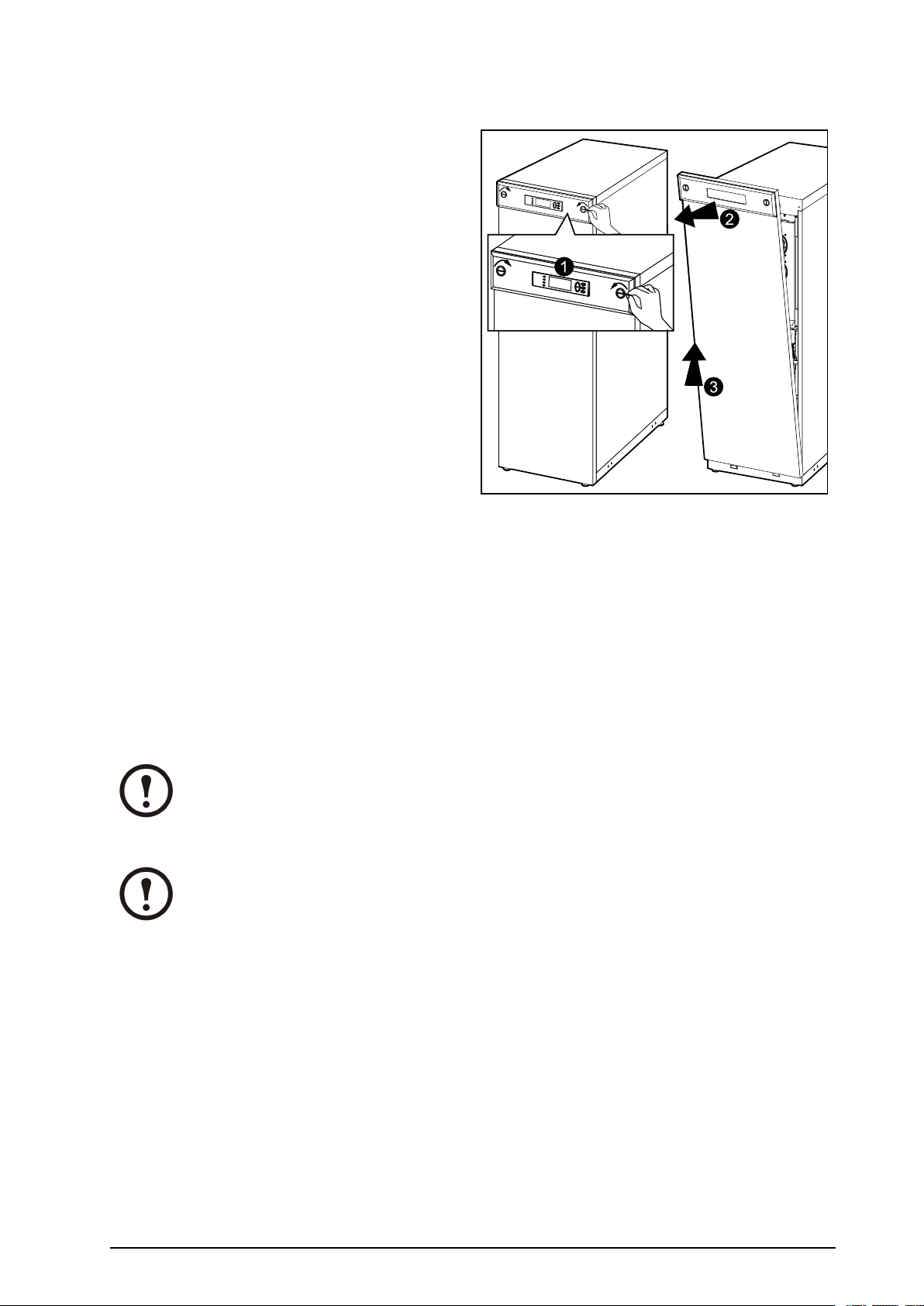
RemovetheFrontPanel
1.Useacoinorsimilartoturnthetwoblacklock
devicesoneithersideofthedisplayinthe
directionofeachothertoaverticalposition.
2.Pushthefrontpanelupwardsandpullit
outwardstodisengagethelockingdeviceat
thetopoftheenclosure.
3.Liftthefrontpanelfreeofthetwoslotsatthe
bottomoftheenclosure.
FloorAnchoring
Therearetwoooranchoringoptionsthatcanbeuseddependingontherequirementsintheinstallation
area:
•Forstability:ReusetheL-shapedbracketsthatsecuredtheenclosuretothepalletduringshipment
forastand-aloneUPS.
•Forseismicanchoring:UseabayingkitthatincludesU-shapedseismicanchoringbrackets.
Note:Allowforenoughworkingspacebehindtheenclosureforelectricalworktobecarried
out(e.g.ifyouwanttoinstallanXRBatteryEnclosureatalaterstage).Minimumrear
clearanceis100mm(3.93in)andmustcomplywithapplicablenationalandlocalcodes.
600mm(23.6in)isrecommended.
Note:Holepositionsareguidelinesonly .
990-1957C-001
MGE™Galaxy™350010-30kV A208/220VSingleandParallelInstallation
9
Page 16
HolePositionsforaStand-aloneUPSEnclosurewithL-shaped
AnchoringBrackets
Note:RecommendedminimumnumberofscrewsperenclosurefortheL-shapedbracketsis
four;oneineachcorner.Recommendedoorboltsize:M8.
ModelWidth:352mm(13.85in)and523mm(20.59in)
HolePositionsforUptoFourUPSUnitsinParallelwithU-shaped
AnchoringBrackets
Note:Recommendedminimumnumberofoorscrewsforthetwocongurationsbelow
is10.
ModelWidth:352mm(13.85in)
10
MGE™Galaxy™350010-30kV A208/220VSingleandParallelInstallation
990-1957C-001
Page 17

ModelWidth:523mm(20.59in)
ConnectFloorAnchoringBracketstotheUPSandXRBattery
EnclosureforStability
Note:FlooranchoringboltsarenotprovidedwiththeUPS.Purchasetheboltslocally
(minimumsize:M8).Followthespecicationsgivenbythemanufactureroftheoor
anchoringsystemwhenboltingtheUPSsystemtotheoor.
1.InstalltheL-shapedooranchoringbrackets
(reusethetwotransportbrackets)andsecure
withtheM6screwsandnuts(provided).
2.Drilltwotosixholesintheoorforeach
bracketandattachthesewithbolts.
990-1957C-001
MGE™Galaxy™350010-30kV A208/220VSingleandParallelInstallation
11
Page 18

RemovetheBatteryModules
1
2
3
Note:Twopeopleareneededtoliftthebatterymodules.
Note:TheXRBatteryEnclosuresshipwithtwobatterymodules.Allbatterymodulesin
theUPSandtheXRBatteryEnclosure(s)mustberemovedbeforeinterconnectingthese
enclosures.
Note:Whenyouremovebatterymodules,startfromthehighestrowandworkyourway
down.
1.Removeallbatterysecuringbrackets(usedtosecurethebatteriesduringtransport)byremoving
theM6Torxscrews.
2.Removetheblindplate.
3.Toreleasethebatteryfromitslockmechanism,gentlypushthebatteryupwardsandthenpullit
outwhilesupportingthebatterywithyourotherhand.
12
MGE™Galaxy™350010-30kV A208/220VSingleandParallelInstallation
990-1957C-001
Page 19

InstalltheBayingKit(Optional)forInterconnectionofEnclosuresand
UPS UPS
2
2
SeismicAnchoring
Caution:Bayingkitsarerequiredinseismicareas.
1.Removethesidepanelsfromtheenclosure(s)togetaccesstotheholesinthebottomframe.
Note:Makesurethattheenclosuresarelevelsothattheycanbeanchoredtoeachother.
2.PositiontwoU-shapedooranchoringbracketsunderoneenclosure;oneoneachside.
Note:TheU-shapedanchoringbracketsare1-2mmhigherthantheopeningbelowthe
enclosuretoinactivatethecasters.Therefore,theenclosuremustbetiltedwhenplacingthe
U-shapedanchoringbracketsundertheenclosure.
990-1957C-001
MGE™Galaxy™350010-30kV A208/220VSingleandParallelInstallation
13
Page 20

3.OneachsideofthesameenclosureinsertamaximumofnineandaminimumoftwoM8screws
3
4
(notprovided)throughholesinthebottomoftheenclosureandthroughholesintheU-shaped
ooranchoringbrackets,andintothepre-drilledoorholes.
4.Fastenthescrews.
5.MovetheadjacentenclosureonitscastersclosetotheenclosurewiththeU-shapedoor
anchoringbrackets.
Note:Iftheadjacentenclosureisonitslevelingfeet,useaforkliftorpalletjacktomoveit
intopositiontoavoiddamagingthelevelingfeet.
14
MGE™Galaxy™350010-30kV A208/220VSingleandParallelInstallation
990-1957C-001
Page 21

6.Inserttheinterconnectionplatesbetweenthetwoenclosures.Oneispositionedtowardthefront
10
5
8
6
7
7
7
7
7
7
UPS
UPS
andtheothertowardtherear.Noticehowthe“wings”ontheinterconnectionplatesrestinslotsat
thetopoftheinnerpanel.
7.AlignthetwoenclosuresandlevelthethreemarkedrowsofboltholesinUPS1withtheholes
inUPS2.
8.Pushthetwoenclosuresrmlytogether.
9.BoltthetwoenclosurestogetherusingthesixM6x25mmscrewsandnutssuppliedinthekit;join
oneholeatthefrontandoneholeattherearoftheenclosuresonthreelevels.
10.PositionthethirdU-shapedooranchoringbracketundertheadjacentenclosure(seeprevious
graphics)andinsertaminimumoftwoooranchoringM8screws(notprovided)throughthe
holesinthebottomoftheenclosureandthroughtheholesintheU-shapedooranchoringbracket,
andintothepredrilledoorholes,andthenfastenthescrews.
990-1957C-001
MGE™Galaxy™350010-30kV A208/220VSingleandParallelInstallation
15
Page 22

InstallXRBatteryEnclosures(Option)
1
4
3
2
1
4
3
2
XR Battery Enclosure UPS
RemovetheCableLandingCoverandBottomPlates
WARNING:Beforecarryingoutthestepsbelow,thesystemmustbeintotalpower
offandthebatteriesmustberemoved.
ToaccessthecablelandingareaintheUPSandtheXRBatteryEnclosure(s),followthisprocedure:
1.LoosenthesixM4screwsfromthecablelandingcoverplateontheUPSandtheXRBattery
Enclosure(s)andthenremovetheplates.
2.Ininstallationswithbusbarconnections,removethescrewsfromthebottomplateontheUPS
andtheXRBatteryEnclosure(s)andthenremovetheplates.
3.Punchholesinthebottomoftheconduitboxestotthesizeoftheconduitpipes.
4.AttachthebottompartoftheconduitboxestothebackoftheUPSandtothebackoftheXR
BatteryEnclosurewithfourscrewseach(ifapplicable).
16
MGE™Galaxy™350010-30kV A208/220VSingleandParallelInstallation
990-1957C-001
Page 23

ConnectBatteryPowerinInstallationswithBusbars
3
2
2
2
WARNING:Beforecarryingoutthestepsbelow,thesystemmustbeintotalpower
offandthebatteriesmustberemoved.
IsolatorInstallationPrinciple
TheisolatorsseparatethebayingkitbusbarfromthesixverticalbusbarsineachXRBatteryEnclosure,
andthe(+),N,and(-)busbarsintheUPS.
1.Guidethebusbarwithisolatorthroughtheadjacentsidepanels.
2.Positiontheisolatorsacrosstheverticalbusbars(Ninthisexample)andthenfastentheisolator
busbarbyusingtheprovidedM5Torxscrews.
3.Securetheisolatortoitsbusbarwithcableties.
990-1957C-001
MGE™Galaxy™350010-30kV A208/220VSingleandParallelInstallation
17
Page 24
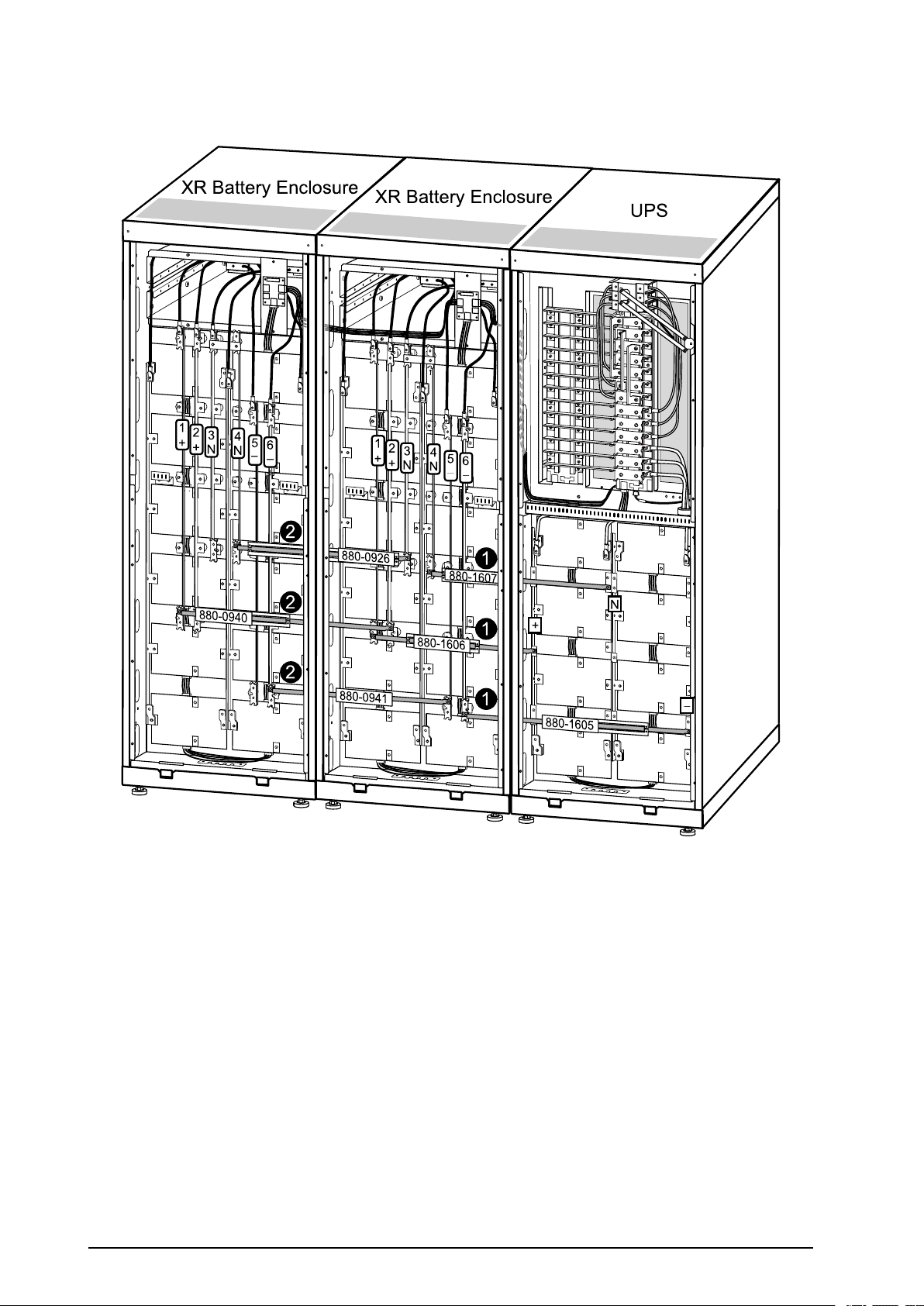
InstallBusbarsin523mm(20.59in)UPSSystemwiththeUPSPlaced
1
1
1
2
2
2
XR Battery Enclosure
XR Battery Enclosure
UPS
totheLeft(seenfromthefront)
1.InstallthefollowingbayingkitbusbarsbetweentheUPSandXR1:
880-1607betweenverticalbusbarNontheUPSandbusbar4onXR1
880-1606betweenverticalbusbar(+)ontheUPSandbusbar1onXR1
880-1605betweenbusbar(-)ontheUPSandbusbar6onXR1
2.InstallthefollowingbayingkitbusbarsbetweenthetwoXRBatteryEnclosures:
880-0926betweenverticalbusbar3onXR1andbusbar4onXR2
880-0940betweenverticalbusbar2onXR1andbusbar1onXR2
880-0941betweenverticalbusbar5onXR1andbusbar6onXR2
18
MGE™Galaxy™350010-30kV A208/220VSingleandParallelInstallation
990-1957C-001
Page 25

InstallBusbarsin523mm(20.59in)UPSSystemwiththeUPSPlaced
1
1
1
2
2
2
XR Battery Enclosure
XR Battery Enclosure
UPS
totheRight(seenfromthefront)
1.InstallthefollowingbayingkitbusbarsbetweentheUPSandXR1:
880-1607betweenverticalbusbarNontheUPSandbusbar3onXR1
880-1605betweenverticalbusbar(+)ontheUPSandbusbar1onXR1
880-1606betweenverticalbusbar(-)ontheUPSandbusbar6onXR1
2.InstallthefollowingbayingkitbusbarsbetweenthetwoXRBatteryEnclosures:
880-0926betweenverticalbusbar4onXR1andverticalbusbar3onXR2
880-0941betweenverticalbusbar2onXR1andverticalbusbar2onXR2
880-0940betweenverticalbusbar5onXR1andverticalbusbar5onXR2
990-1957C-001
MGE™Galaxy™350010-30kV A208/220VSingleandParallelInstallation
19
Page 26

InstallBusbarsin352mm(13.85in)UPSSystemwiththeUPSPlaced
1
1
1
2
2
2
XR Battery Enclosure
XR Battery Enclosure
UPS
totheRight(seenfromthefront)
1.InstallthefollowingbayingkitbusbarsbetweentheUPSandXR1:
880-1604betweenverticalbusbarNontheUPSandbusbar4onXR1
880-0939betweenverticalbusbar(+)ontheUPSandbusbar1onXR1
880-1604betweenverticalbusbar(-)ontheUPSandbusbar6onXR1
2.InstallthefollowingbayingkitbusbarsbetweentwoXRBatteryEnclosures:
880-0926betweenverticalbusbar3onXR1andbusbar4onXR2
880-0940betweenverticalbusbar2onXR1andbusbar1onXR2
880-0941betweenverticalbusbar5onXR1andbusbar6onXR2
20
MGE™Galaxy™350010-30kV A208/220VSingleandParallelInstallation
990-1957C-001
Page 27

InstallBusbarsin352mm(13.85in)UPSSystemwiththeUPSPlaced
1
1
1
2
2
2
XR Battery Enclosure
XR Battery Enclosure
UPS
totheLeft(seenfromthefront)
1.InstallthefollowingbayingkitbusbarsbetweentheUPSandXR1:
880-1604betweenverticalbusbarNontheUPSandbusbar3onXR1
880-1604betweenverticalbusbar(+)ontheUPSandbusbar1onXR1
880-0939betweenverticalbusbar(-)ontheUPSandbusbar6onXR1
2.InstallthefollowingbayingkitbusbarsbetweentwoXRBatteryEnclosures:
880-0926betweenverticalbusbar4onXR1andverticalbusbar3onXR2
880-0941betweenverticalbusbar2onXR1andverticalbusbar1onXR2
880-0940betweenverticalbusbar5onXR1andverticalbusbar6onXR2
990-1957C-001
MGE™Galaxy™350010-30kV A208/220VSingleandParallelInstallation
21
Page 28

ConnectBatteryPowerinInstallationswithCables
5
4
4
7
6
6
6
1
3
2
XR Battery Enclosure
UPS
To XR 2
6
ConnectPowerCablesBetweentheUPSandtheXRBatteryEnclosure
WARNING:Beforecarryingoutthestepsbelow,thesystemmustbeintotalpower
offandthebatteriesmustberemoved.
WARNING:Eachfreestandingcabinetmustbeseparatelyconnectedtothe
equipotentialbondingsystem(protectiveearthing).
Note:Theterminalsareonlysuitableforconnectionofcoppercables.
22
MGE™Galaxy™350010-30kV A208/220VSingleandParallelInstallation
990-1957C-001
Page 29

1.IntheUPS,feedthecableupthroughtheconduitboxorthroughthetransparentcableroute
bracket(notshown).
2.ConnecttheBAT+,BA T -,N,andgroundcablestothebusbarsintheUPS.
3.Securethecablestotheperforatedbracketwithcableties.
4.Equipthecablewithconduits(ifapplicable).
5.IntheXRBatteryEnclosure,feedthecableupthroughtheconduitbox(ifapplicable)tothe
cablelandingarea.
6.Connectthe(+)cabletobusbarno.1(+),connecttheNcabletobusbarno.4(N),the(-)cable
tobusbarno.6(-),andthegroundcabletotheterminalinthetopofthecabinet.Bundlethe
cablesusingthesuppliedcableties.
7.Securethecabletotheperforatedbracketwithcableties.
8.Attachthetoppartoftheconduitbox(ifapplicable).
ConnectPowerCablesbetweenTwoXRBatteryEnclosures
WARNING:Beforecarryingoutthestepsbelow,thesystemmustbeintotalpower
offandthebatteriesmustberemoved.
WARNING:Eachfreestandingcabinetmustbeseparatelyconnectedtothe
equipotentialbondingsystem(protectiveearthing).
Note:Theterminalsareonlysuitableforconnectionofcoppercables.
990-1957C-001
MGE™Galaxy™350010-30kV A208/220VSingleandParallelInstallation
23
Page 30

5
4
7
1
3
2
2
2
6
6
6
XR Battery EnclosureXR Battery Enclosure
To XR 2
From UPS
1.FeedthecableupthroughtheconduitboxonXR1orthroughthetransparentcableroutebracket
(notshown)tothecableconnectionarea.
2.Connectthe(-)cabletobusbarno.5(-),theNcabletobusbarno.3(N),the(+)cabletobusbar
no.2(+)inXR1,andthegroundcabletotheterminalinthetopofthecabinet.
3.Securethecabletotheperforatedbracketwithcableties.
4.Equipthecablewithconduits(ifapplicable).
5.Feedthecableupintotheconduitbox(optionalfor400Vversions)onXR2.
6.Connectthe(-)cabletobusbarno.6(-),theNcabletobusbarno.4(N),andthe(+)cableto
busbarno.1(+)inXR2,andthegroundcabletotheterminalinthetopofthecabinet.Bundlethe
cablesusingthesuppliedcableties.
7.Securethecabletotheperforatedbracketwithcableties.
8.Attachthetoppartoftheconduitbox(ifapplicable).
24
MGE™Galaxy™350010-30kV A208/220VSingleandParallelInstallation
990-1957C-001
Page 31

ConnectthePowerCablestotheUPS
SingleSystem10-30kVA208V
990-1957C-001
MGE™Galaxy™350010-30kV A208/220VSingleandParallelInstallation
25
Page 32

SingleSystem10-30kVA480V
26
MGE™Galaxy™350010-30kV A208/220VSingleandParallelInstallation
990-1957C-001
Page 33

PrepareforCables
A
B
C
D
5
5
6
4
7
9
8
8
BottomCableEntry
1.FromtherearoftheUPS,loosenthesixM4
screwsfromtheuppercover(thecablelanding
area),andremove.Savethescrewsforlater
use
2.LoosenthetwoM4screws(oneoneachside)
fromthetoppartoftheconduitbox.Loosen
theM4screwsattachingittothebottompart
(twoscrewsin352mm(13.8in)enclosure
threescrewsina523mm(20in)enclosure)
andremove.Savethescrewsforlateruse.
3.LoosenthefourM4screws(twooneachside)
fromtheconduitboxandremove.Savethe
screwsforlateruse.
4.Punchasmanyholesasneededinthemarked
areasofthebottomconduitbox.
5.Attachtheconduitboxbottomtotheenclosure
(reusethescrewsfromstep3).
6.Attachconduitstotheconduitbox.
7.Runthecablesthroughtheconduits,the
bottomoftheconduitbox,andupintothe
cablelandingarea.
A.Bypass
B.Output
C.Battery
D.Input
8.Attachconduitboxtoptotheconduitbox
bottomandtotheenclosurereusingthescrews
fromstep2.
9.Fastenthecableswithcableties.
990-1957C-001
MGE™Galaxy™350010-30kV A208/220VSingleandParallelInstallation
27
Page 34

ConnecttheACInputandACOutputCables
1
2
3
C
B
A
A
1
WARNING:UseONLYcompressiontypelugs.Donotloosenoraddcablestoany
factorypreinstalledcablesonbusbars.Usetheupperfrontpartofbusbarfor
connectiononly.
Note:Theterminalsareonlysuitableforconnectionofcoppercables.
SingleMains
1.ConnecttheACinputcablesandtheneutralto
theinputcablelandings.
2.ConnecttheACoutputcablesandtheneutral
totheoutputcablelandings.
3.Connectthegroundcablestothestuds(earth
symbolbeneath)usingascrew.
DualMains
1.RemovethethreebusbarsA,B,andCby
removingtwoM6screwsfromeachbusbar.
28
MGE™Galaxy™350010-30kV A208/220VSingleandParallelInstallation
990-1957C-001
Page 35

2.ConnecttheACinputcablesandtheneutralto
5
2
3
4
1
theinputcablelandings.
3.Connectthebypasscablesandtheneutralto
thebypasscablelandings.
4.Connecttheoutputcablesandtheneutralto
theoutputcablelandings.
5.Connectthegroundcablestothestuds(earth
symbolbeneath)usingascrew.
ConnecttheDCBatteryCables(ifapplicable)
1.ConnectbatterycablesBA T+,BAT -,andNto
thebatterycablelandings.Bundlethecables
usingthesuppliedcableties.
990-1957C-001
MGE™Galaxy™350010-30kV A208/220VSingleandParallelInstallation
29
Page 36

ConnecttheCommunicationCables
PrepareforCommunicationCables
WARNING:MakesurethattheUPSiscompletelyOFFastheconnectorsarevery
closetothepowerbusbars.
WARNING:Beforeconnectingthecommunicationcables,placethetwosupplied
ferritesoverthecommunicationcables.Runthecablethreetimesthroughtheferrite
toreducenoise.
30
MGE™Galaxy™350010-30kV A208/220VSingleandParallelInstallation
990-1957C-001
Page 37

OverviewofPinConnections
J106
J108pinconnections:
1:NormallyopenEPO
2:NormallyopenEPOreturn
3:NormallyclosedEPO
4:NormalyclosedEPOreturn
5:+24VSELVsupply
6:SEL Vground
J106pinconnections:
8:Ext.chargingcontrolreturn
7:Externalcontrolofcharging
6:Q3activereturn
5:Q3active
4:Batterymeasurementsupply*
3:Batteryunitquantity*
2:Max.batterytemperature*
1:Batterymeasurementreturn*
*ShouldbeusedwithAPCXRBatteryEnclosures
Pins1to4areforbatterymeasurement(onlyapplicabletoMGEGalaxy3500XRBatteryEnclosures).
Pins5and6areforexternalmaintenancebypassQ3(auxiliaryswitchN/Ctype).WhenQ3isclosed,
signalsarefedbacktotheUPScontroller.
Pins7and8areforexternalchargecontrol.When7and8areclosed,theUPSchargesbatterieswitha
pre-denedpercentage(0–25–50–75–100%)ofthemaximumchargingpower.T obeusedingenerator
applications,orifspecialcodesrequirecontrolofcharging.WhenQ3isclosed,signalsarefedback
totheUPScontroller.
990-1957C-001
MGE™Galaxy™350010-30kV A208/220VSingleandParallelInstallation
31
Page 38

EPOinSingleSystems
ConnecttheEPOcableusingoneofthefollowingfourwiringcongurations.
Note:Useonly1-1½mm²copperwirefortheconnectionoftheEmergencyPowerOff
(EPO)andotheroptionalequipment.
Note:TheUPSmustbeconnectedtoeitheradrycontactora24VDCEPO(Emergency
PowerOff)switch.
Note:TheexternalEPO+24VDC,1500mAcircuitcanbesuppliedthroughothervendors.
1.DryContactsNormallyOpen:EPOis
activatedwhenpin1isconnectedtopins3and
5.Connections:2-4-6,3-5,and1(Normally
Open).
2.+24VNormallyOpen:EPOisactivated
whenanisolatedSELV24VDCvoltageis
suppliedonpin1withreferencetopin2.
Connections:3-5and4-6.
3.DryContactsNormallyClosed:EPOis
activatedwhenaconnectionfrompin3to5is
opened.Connections:4-6.
4.+24VNormallyClosed:EPOisactivated
whenaSELV24VDCvoltageisremoved
frompin3withreferencetopin4.
32
MGE™Galaxy™350010-30kV A208/220VSingleandParallelInstallation
990-1957C-001
Page 39

EPOinParallelSystems
InparallelsystemseachUPSunitmusthaveitsowndrycontact(voltagefree)connectedtoJ108.The
drawingbelowshowsa“NormallyClosed”installationofthreeUPSunitsinparallel.
WARNING:ForparallelandseparatesystemswithcommonEPO,eachUPSunitmust
beconnectedtoaseparatedrycontact.
WARNING:ParallelEPOwiringbetweenmoreUPSunitscanresultincriticalUPS
malfunctioning.
990-1957C-001
MGE™Galaxy™350010-30kV A208/220VSingleandParallelInstallation
33
Page 40

ConnectCommunicationCablesbetweenUPSandXR
1
1
3 2
2
XR Battery Enclosure UPS
BatteryEnclosure
1.FeedthecablefrompinconnectionJ106intheUPSdownthroughtheconduit(ifapplicable).
2.RunthecableupintotheXRconduitandconnectittopinconnectionJ200intheXRBattery
Enclosure.
3.IfyouuseasecondXR,runthecablefrompinconnectionJ204inXR1topinconnectionJ200in
XR2.
34
MGE™Galaxy™350010-30kV A208/220VSingleandParallelInstallation
990-1957C-001
Page 41

ConnectAPCCommunicationOptions
6
1
2
3
4
5
Note:Thecableroutingofthepowerchutesoftwareandthetemperaturesensorisidentical.
Note:ThetemperaturesensorisprovidedinaplasticbagattachedtothefrontoftheUPS
behindthefrontpanel.
1.Removethetwoscrewsfromthecable-inletat
thefrontandremovethecable-inletplate.
2.Guidethecablethroughtheholeinthebottom
plateandupthroughthecable-inlet.
3.Guidethecablethroughthesidepanelhole
andrunthecableupwardsinsidethepanel.
4.Pullthecableoutofthesidepanelthrough
theholeclosesttotheNetworkManagement
Cardarea.
5.Plugthecableintotheprobesocket/
PowerChuteinlet.
6.Reattachthecable-inletplate.
990-1957C-001
MGE™Galaxy™350010-30kV A208/220VSingleandParallelInstallation
35
Page 42

ConnectCommunicationCablesinParallelSystem
Note:Thecablesmustberunbytheelectricianbutnotattached.Theeldserviceengineer
fromSchneiderElectricwillattachallcablestotheUPSunit(s)andinstalltheparallel
communicationbox.Thebelowisforoverviewonly .
Note:ThePBuscablesrunfromUPS1toUPS2toUPS3andUPS4ifyourconguration
consistsof4UPSunits.
Note:ThePBuscablesarelabelledPBus1andPBus2.
OverviewofthePBusCables
Note:Thecablesmustberunbytheelectricianbutnotattached.Theeldserviceengineer
fromSchneiderElectricwillattachallcablestotheUPSunit(s)andinstalltheparallel
communicationbox.Thebelowisforoverviewonly .
Note:ThePBuscablesrunfromUPS1toUPS2toUPS3andUPS4ifyourconguration
consistsof4UPSunits.
Note:ThePBuscablesarelabelledPBus1andPBus2.
Note:PBus1cablesmustbekepttogether,andPBus2cablesmustbekepttogether.If
youbymistakerunacablebetweenaPBUS1terminalandaPBUS2terminal,youwill
benotiedbythedisplay.
Note:IfthecongurationconsistsofonlytwoUPSunits,theterminatorsmustbeinstalled
inUPS1and2.WiththreeUPSunits,theterminatorsmustbeinstalledinUPS1and3.
36
MGE™Galaxy™350010-30kV A208/220VSingleandParallelInstallation
990-1957C-001
Page 43

PrepareforCables
RemovetheBatteries
Note:See“RemovetheBatteryModules“forinformationonhowtoremovethebatteries.
RuntheCommunicationCables
Threedifferentwaysofroutingcables
Note:Theenclosuresinaparallelsystemcanbekeptapart,ortheycanbeassembledwith
interconnectionplates.Iftheenclosuresarekeptapart,thecommunicationcablescanberun
inconduits(ifapplicable).
TheroutingofcablesbetweentheUPSunitscanbedoneinthreedifferentways.
•UPSunitsapart(withoutconduitsandwithoutinterconnectionplates)
•UPSunitsbayedtogether(withoutconduitsandwithinterconnectionplates)
•UPSunitsapartorbayedtogether(withconduitsandoptionalinterconnectionplates)
990-1957C-001
MGE™Galaxy™350010-30kV A208/220VSingleandParallelInstallation
37
Page 44

UPSUnitsApartwithoutConduitsandInterconnection
7
6
7
2
2
8
8
4
5
7
7
3
UPS 1
UPS 2
PBus
PBus
PBus
ABus
ABus
1.Removethefrontpanel(notshown).
2.Loosenthetwoscrewsfromthecable-inletplatesatthebottomplateofUPS1andUPS2and
thenremovetheplates.
3.FromUPS1:RunthetwoPBuscablestotheslotsontheleftsideoftheenclosureanddown
insidethepanel.
4.Fromthelowestslot,shoutthecablesfromthesidepanelandrunthesedownthroughthecable
inletandthroughtheroundholeatthebottom.
5.RunthePBuscablestoUPS2andtotheslotsontheleftsideoftheenclosureandupinside
thepanel.
6.TakeoutthePBuscablesandleavetheseunattachedtotheparallelbox.
7.RuntheABuscablefromthemaintenancebypasspaneltotheslotsontheleftsideoftheenclosure
andupinsidethepanelthesamewayasforthePBuscables.
8.Reattachthecable-inletcovers.
9.Fastenthecableswithcablesties.
38
MGE™Galaxy™350010-30kV A208/220VSingleandParallelInstallation
990-1957C-001
Page 45

Note:ProceedtheroutingofcablesintoUPS3andUPS4,ifapplicable.
3
7
6
7
4
2
7
5
2
8
8
UPS 1
UPS 2
PBus
PBus
PBus
ABus
ABus
UPSUnitsBayedT ogetherwithoutConduits
1.Removethefrontpanelandthetopcover(notshown).
2.Loosenthetwoscrewsfromthecable-inletplatesatthebottomplateofUPS1andUPS2and
thenremovetheplates.
3.FromUPS1:RunthetwoPBuscablestotheslotsontheleftsideoftheenclosureanddown
insidethepanel.
4.Fromthelowestslot,takeoutthecablesfromthesidepanel,runthecablesacrossandthroughthe
cableinletsofthetwosidepanels.
990-1957C-001
MGE™Galaxy™350010-30kV A208/220VSingleandParallelInstallation
39
Page 46
5.FromthebottomofUPS2,runthePBuscablestotheslotsontheleftsideoftheenclosureand
2
A
A
upinsidethepanel.
6.TakeoutthePBuscablesandleavetheseunattached.
7.RuntheABuscablefromthemaintenancebypasspaneltotheslotsontheleftsideoftheenclosure
andupinsidethepanelthesamewayasforthePBuscables.
8.Reattachthecable-inletcoverplates.
9.Fastenthecableswithcableties.
Note:ProceedtheroutingofcablesintoUPS3andUPS4,ifapplicable.
UPSUnitsApartorBayedT ogetherwithConduits
Note:Whenenclosuresareassembledwithinterconnectionplatesandboltedtogether,the
PBuscablescanberuninsidetheenclosuresandthenonlytheABuscablehastoberunin
aconduit(ifapplicable).
1.Removethefrontpanel(notshown).
2.Removethetopcover:
A.Loosenthesixscrewsofthetopcover(fouratthefrontandtwoattheback).
B.Liftupfromthebackandpushforwardtofreethecover.
C.LeavethecoverunattachedontopoftheUPS.
3.RemovetheconduitplateatthebackoftheUPScoveranddrillholescenteredinthesmall
pre-drilledholes.2cm(3/4in)isrecommendedforconduits.
4.RuntheABusandthePBuscablesthroughtheconduitholesintotheinsideofthetopcoveron
UPS1.LeavethecablesontopoftheUPS.
5.Attachconduitswith2cm(3/4in)ttings(notsupplied).
6.RunconduitswithPBuscablestoUPS2.Pullthecablesthroughthetopcoverconduitplateand
leavethecablesontopoftheUPSasshown.
7.AttachconduitstoUPS2with2cm(3/4in)ttings(notsupplied).
8.RuntheABuscables(inconduitsifapplicable)tothemaintenancebypasspanel.
40
MGE™Galaxy™350010-30kV A208/220VSingleandParallelInstallation
990-1957C-001
Page 47

6
7
5
4
8
8
UPS 2 UPS 1
9.Reinstallthetopcover.
Note:ProceedtheroutingofcablesintoUPS3andUPS4,ifapplicable.
990-1957C-001
MGE™Galaxy™350010-30kV A208/220VSingleandParallelInstallation
41
Page 48

InstallSeismicOption
InstalltheSeismicBatteryLock
Note:Inseismicareas,disposeofthebatterysecuringbracketsthatwereusedtosecurethe
batteriesduringtransportandusetheseismicbatterylockstosecurethebatteries.
Requiredparts:
•Fourbatterylocksand12M5screwsfornarrow
batteryenclosures.
•Sixbatterylocksand30M5screwsforwide
batteryenclosures.
1.Placethebatterylockbelowthebatteryrow.
2.SecurethebatterylockbytheprovidedM5
screws.
InstalltheSeismicStabilizingBrackets
Requiredparts:
•UPS,BatteryEnclosureandTransformer
–Eight10mmttings
–18M6nutwashers
–Onehorizontalbracket
–Fourstabilizingbrackets
•MaintenanceBypassPanel(MBP)
–Eight2mmttings
–18M6nutwashers
–Onehorizontalbracket
–Fourstabilizingbrackets
42
MGE™Galaxy™350010-30kV A208/220VSingleandParallelInstallation
990-1957C-001
Page 49

Note:WhenMBPsandtransformer
cabinetsareinstalledupagainstother
frames,itissufcienttoinstallonly
onecrosswithahorizontalbracket
intoporlowerposition.
1.Insertpinsofthettingintotheindicated
mountingholes.
2.Mountthebracketsinthettingsandsecure.
Frontview
990-1957C-001
MGE™Galaxy™350010-30kV A208/220VSingleandParallelInstallation
43
Page 50

FinalMechanicalInstallation
ConnectBatterySecuringBracketsforStability
Caution:W aituntilthesystemisreadytobepoweredupbeforeinstallingbatteries.
Failuretodosocanresultinadeepdischargeofthebatteriesandcausepermanentdamage
(thetimefromthebatteryinstallationtimetilltheUPSispoweredupshouldnotexceed
72hoursor3days).
Note:Thebatterysecuringbracketsareonlyusedinnon-seismicareasforstability,and
whenseismicbatterylocksarenotpartoftheinstallation.
1.Installthebatteriesbypushingthemallthewayintotheenclosure.
2.Ifrequired,installthebatterysecuringbrackets(A)toholdthebatteriesrmlyinplace.NOTE:
Donotinstallthebracketsthesamewaytheywerepositionedwhentheenclosurearrived.Rotate
thebrackets180°andreinstall.
Note:BatterysecuringbracketsaredeliveredwiththeUPSandXRBatteryEnclosureand
installedinfrontofthebatteries.Batterysecuringbracketsforadditionalbatteriescanbe
purchased.RefertooptionSUVTOPT003:APCSmart-UPSVTBatteryLockKitforone
BatteryModule(twobatteries).
44
MGE™Galaxy™350010-30kV A208/220VSingleandParallelInstallation
990-1957C-001
Page 51

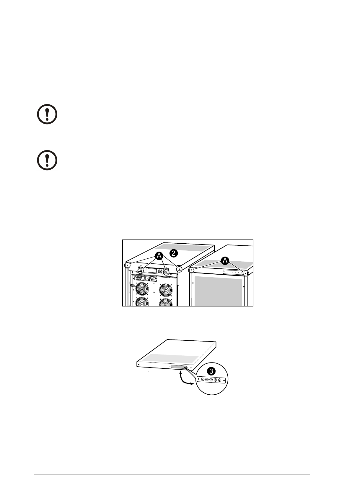
ReinstalltheTopCoverandtheFrontPanel
M
o
d
el
:
Se
rial
:
B
A
TTER
Y U
NI
T
M
o
d
el
:
Se
ria
l:
B
A
TT
ER
Y
U
NI
T
M
o
d
e
l
:
Se
r
i
al
:
B
ATTERY
U
NI
T
M
o
d
e
l
:
Se
ria
l:
B
ATTERY
UNIT
M
o
d
e
l
:
Se
ria
l:
BATTE
R
Y UNIT
M
o
d
e
l:
Se
r
ia
l:
B
A
TTE
R
Y
U
NIT
M
o
d
e
l:
Se
ria
l:
BAT
TER
Y
U
NIT
M
o
d
e
l:
Se
r
i
al
:
B
ATTER
Y UNIT
2
1.Reinstallthetopcoverbyfasteningthefourscrewsatthefrontandthetwoscrewsattheback.
2.Insertthetwotapsatthebottomofthefrontpanelintothetwoslotsatthebottomoftheenclosure.
3.Pushthefrontpanelforwarduntilitengagesthelockingdevicesatthetopoftheenclosure.
4.Useascrewdrivertosetthelockmechanismtothelockedposition.
990-1957C-001
MGE™Galaxy™350010-30kV A208/220VSingleandParallelInstallation
45
Page 52

WorldwideCustomerSupport
Customersupportisavailableatnochargeviae-mailortelephone.Contactinformationisavailableat
www.apc.com/support/contact
©APCbySchneiderElectric.APCandtheAPClogoareownedbySchneiderElectricIndustries
S.A.S.,AmericanPowerConversionCorporation,ortheirafliatedcompanies.Allothertrademarks
arepropertyoftheirrespectiveowners.
990-1957C-00106/2012
 Loading...